WO2015152157A1 - 偏光板、画像表示装置および液晶表示装置 - Google Patents
偏光板、画像表示装置および液晶表示装置 Download PDFInfo
- Publication number
- WO2015152157A1 WO2015152157A1 PCT/JP2015/059939 JP2015059939W WO2015152157A1 WO 2015152157 A1 WO2015152157 A1 WO 2015152157A1 JP 2015059939 W JP2015059939 W JP 2015059939W WO 2015152157 A1 WO2015152157 A1 WO 2015152157A1
- Authority
- WO
- WIPO (PCT)
- Prior art keywords
- polarizing plate
- film
- polarizer
- liquid crystal
- thickness
- Prior art date
- Legal status (The legal status is an assumption and is not a legal conclusion. Google has not performed a legal analysis and makes no representation as to the accuracy of the status listed.)
- Ceased
Links
Images


Classifications
-
- G—PHYSICS
- G02—OPTICS
- G02B—OPTICAL ELEMENTS, SYSTEMS OR APPARATUS
- G02B5/00—Optical elements other than lenses
- G02B5/30—Polarising elements
- G02B5/3016—Polarising elements involving passive liquid crystal elements
-
- G—PHYSICS
- G02—OPTICS
- G02B—OPTICAL ELEMENTS, SYSTEMS OR APPARATUS
- G02B5/00—Optical elements other than lenses
- G02B5/30—Polarising elements
- G02B5/3025—Polarisers, i.e. arrangements capable of producing a definite output polarisation state from an unpolarised input state
- G02B5/3033—Polarisers, i.e. arrangements capable of producing a definite output polarisation state from an unpolarised input state in the form of a thin sheet or foil, e.g. Polaroid
-
- G—PHYSICS
- G02—OPTICS
- G02F—OPTICAL DEVICES OR ARRANGEMENTS FOR THE CONTROL OF LIGHT BY MODIFICATION OF THE OPTICAL PROPERTIES OF THE MEDIA OF THE ELEMENTS INVOLVED THEREIN; NON-LINEAR OPTICS; FREQUENCY-CHANGING OF LIGHT; OPTICAL LOGIC ELEMENTS; OPTICAL ANALOGUE/DIGITAL CONVERTERS
- G02F1/00—Devices or arrangements for the control of the intensity, colour, phase, polarisation or direction of light arriving from an independent light source, e.g. switching, gating or modulating; Non-linear optics
- G02F1/01—Devices or arrangements for the control of the intensity, colour, phase, polarisation or direction of light arriving from an independent light source, e.g. switching, gating or modulating; Non-linear optics for the control of the intensity, phase, polarisation or colour
- G02F1/13—Devices or arrangements for the control of the intensity, colour, phase, polarisation or direction of light arriving from an independent light source, e.g. switching, gating or modulating; Non-linear optics for the control of the intensity, phase, polarisation or colour based on liquid crystals, e.g. single liquid crystal display cells
- G02F1/133—Constructional arrangements; Operation of liquid crystal cells; Circuit arrangements
- G02F1/1333—Constructional arrangements; Manufacturing methods
- G02F1/1335—Structural association of cells with optical devices, e.g. polarisers or reflectors
- G02F1/133528—Polarisers
-
- G—PHYSICS
- G02—OPTICS
- G02F—OPTICAL DEVICES OR ARRANGEMENTS FOR THE CONTROL OF LIGHT BY MODIFICATION OF THE OPTICAL PROPERTIES OF THE MEDIA OF THE ELEMENTS INVOLVED THEREIN; NON-LINEAR OPTICS; FREQUENCY-CHANGING OF LIGHT; OPTICAL LOGIC ELEMENTS; OPTICAL ANALOGUE/DIGITAL CONVERTERS
- G02F2201/00—Constructional arrangements not provided for in groups G02F1/00 - G02F7/00
- G02F2201/50—Protective arrangements
-
- G—PHYSICS
- G02—OPTICS
- G02F—OPTICAL DEVICES OR ARRANGEMENTS FOR THE CONTROL OF LIGHT BY MODIFICATION OF THE OPTICAL PROPERTIES OF THE MEDIA OF THE ELEMENTS INVOLVED THEREIN; NON-LINEAR OPTICS; FREQUENCY-CHANGING OF LIGHT; OPTICAL LOGIC ELEMENTS; OPTICAL ANALOGUE/DIGITAL CONVERTERS
- G02F2201/00—Constructional arrangements not provided for in groups G02F1/00 - G02F7/00
- G02F2201/54—Arrangements for reducing warping-twist
Definitions
- the present invention relates to a polarizing plate, an image display device, and a liquid crystal display device.
- a polarizer is manufactured using a polyvinyl alcohol-type resin film. More specifically, it is produced by adsorbing and orienting a dichroic dye or dichroic dye such as iodine on a polyvinyl alcohol-based resin film and then uniaxially stretching. Since such a polarizer is inferior in mechanical strength, a polarizer protective film (protective film) such as TAC (film made of saponified triacetyl cellulose) is bonded to the polarizer and used as a polarizing plate. has been.
- Patent Document 1 discloses a polarizing plate including a polarizer and one polarizing plate protective film (claim 1, paragraph [0171], etc.).
- an object of the present invention is to provide a polarizing plate that is less likely to curl due to environmental changes, and an image display device and a liquid crystal display device including the polarizing plate.
- the present inventors have found that curling due to environmental changes is suppressed by using a release film having a specific elastic modulus and thickness, and have reached the present invention. That is, the present inventors have found that the above problem can be solved by the following configuration.
- a polarizing plate comprising a polarizer, a protective film, and a release film in this order,
- the elastic modulus of the release film is 2.0 GPa or more
- a polarizing plate comprising a liquid crystal layer, The polarizing plate as described in said (1) or (2) provided with the said liquid-crystal layer, the said polarizer, the said protective film, and the said peeling film in this order.
- An image display device comprising the polarizing plate according to any one of (1) to (3) and a display element.
- a liquid crystal display device comprising the polarizing plate according to any one of (1) to (3) and a liquid crystal cell.
- a polarizing plate that hardly causes curling due to environmental changes (that is, excellent in curling resistance), and an image display device and a liquid crystal display device including the polarizing plate.
- the (meth) acryloyl group represents an acryloyl group or a methacryloyl group.
- a numerical range expressed using “to” means a range including numerical values described before and after “to” as a lower limit value and an upper limit value.
- the polarizing plate of the present invention is a polarizing plate comprising a polarizer, a protective film, and a release film in this order, and the elastic modulus of the release film is 2.0 GPa or more, and the thickness P [ ⁇ m] of the polarizer.
- the thickness Q [ ⁇ m] of the protective film and the thickness T [ ⁇ m] of the release film satisfy the formula (A) described later.
- the polarizing plate of the present invention is considered to exhibit excellent curl resistance by taking such a configuration. The reason is not clear, but it is presumed that it is as follows.
- the polarizing plate is a laminate composed of a plurality of members (polarizer, protective film, etc.).
- each member constituting the polarizing plate has a different coefficient of thermal expansion or a coefficient of linear expansion (humidity dimensional change)
- the polarizing plate of the present invention includes a release film having a specific elastic modulus. Therefore, even if the environment to which the polarizing plate is exposed is changed, it is considered that the release film can suppress the dimensional change of each member.
- the thickness of the release film satisfies a specific relationship with the thickness of the polarizer and the thickness of the protective film, the balance of stress generated inside the polarizing plate is extremely high.
- the specific relational expression indicates that the greater the thickness of the polarizer, the thicker the release film necessary to suppress curling, and vice versa. This is based on the knowledge obtained by the inventor's study that the thickness of the film is reduced. As a result, the polarizing plate of the present invention is considered to suppress curling even if the environment to which the polarizing plate is exposed changes.
- the polarizing plate of this invention As a 1st embodiment of the polarizing plate of this invention, the polarizing plate provided with a polarizer, a protective film, and a peeling film in this order is mentioned.
- the release film is usually released from the polarizing plate after the polarizing plate is bonded to the adherend.
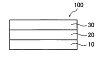
- FIG. 1 is a schematic cross-sectional view of a polarizing plate 100 which is a first embodiment of the polarizing plate of the present invention.
- the polarizing plate 100 includes a polarizer 10, a protective film 20, and a release film 30 in this order.
- polarizer the polarizer, the protective film, and the release film will be described.
- the polarizer may be a member having a function of converting light into specific linearly polarized light.
- an absorbing polarizer, a reflective polarizer, or the like can be used.
- an iodine polarizer, a dye polarizer using a dichroic dye, a polyene polarizer, and the like are used.
- Iodine polarizers and dye polarizers include coating polarizers and stretchable polarizers, both of which can be applied, but polarizers made by adsorbing iodine or dichroic dyes to stretched polyvinyl alcohol Is preferred.
- a polarizer in which thin films having different birefringence are stacked, a wire grid polarizer, a polarizer in which a cholesteric liquid crystal having a selective reflection region and a quarter wavelength plate are combined, or the like is used.
- a polyvinyl alcohol (PVA) resin in particular, at least one selected from the group consisting of polyvinyl alcohol and an ethylene-vinyl alcohol copolymer
- PVA polyvinyl alcohol
- it is a polarizer containing.
- the elastic modulus of the polarizer is not particularly limited, but is preferably 1.0 to 20.0 GPa, more preferably 5.0 to 10.0 GPa.
- the elastic modulus in the present invention is a value in a direction in which the elastic modulus is calculated eight times by changing the measurement direction by 45 ° with respect to the sample by the following method, and the curl is maximum.
- the curl evaluation method is as described in ⁇ Evaluation of curl resistance> described later.
- the thickness of the polarizer is not particularly limited as long as the following formula (A) is satisfied. However, the thickness is preferably 1.0 to 50.0 ⁇ m, and among these, 2.0 to 20 for the reason that the curl resistance is more excellent. The thickness is more preferably 0.0 ⁇ m, and even more preferably 3.0 to 10.0 ⁇ m.
- the protective film is mainly a film for protecting the above-described polarizer.
- a cellulose polymer Acrylic polymer which has acrylic ester polymer, such as a polymethylmethacrylate and a lactone ring containing polymer; Thermoplastic norbornene-type polymer; Polycarbonate-type polymer Polyester polymers such as polyethylene terephthalate and polyethylene naphthalate; styrene polymers such as polystyrene and acrylonitrile / styrene copolymer (AS resin); polyolefin polymers such as polyethylene, polypropylene and ethylene / propylene copolymer; vinyl chloride Amide polymers such as nylon and aromatic polyamide; imide polymers; sulfone polymers; polyether sulfone polymers; polyether ether ketone poly Chromatography; polyphenylene sulf
- a cellulose polymer represented by triacetyl cellulose (hereinafter also referred to as “cellulose acylate”), which has been used as a transparent protective film of a conventionally known polarizing plate, can be preferably used.
- cellulose acylate triacetyl cellulose
- acrylic polymer examples include polymethyl methacrylate and lactone ring-containing polymers described in paragraphs [0017] to [0107] of JP-A-2009-98605.
- the elastic modulus of the protective film is not particularly limited, but is preferably 1.0 to 20.0 GPa, and more preferably 1.0 to 15.0 GPa for the reason that the curl resistance is more excellent. It is more preferably 2.0 to 12.0 GPa, particularly preferably 2.0 to 10.0 GPa.
- the method for measuring the elastic modulus is as described above.
- the thickness of the protective film is not particularly limited as long as the following formula (A) is satisfied.
- the thickness is preferably 1.0 to 100.0 ⁇ m, among which 10.0 to 80 for the reason that the curl resistance is more excellent.
- the thickness is more preferably 0.0 ⁇ m, and further preferably 10.0 to 40.0 ⁇ m.
- the humidity dimension change of the protective film is not particularly limited.
- the change in humidity dimension is a value measured by the following method. That is, prepare a sample with a length of 12 cm (measurement direction) and a width of 3 cm, and make pin holes in the sample at an interval of 10 cm, and after conditioning for 6 hours at 25 ° C. and a relative humidity of 10%, To measure the length (measured value is L 0 ). Next, the sample is conditioned for 6 hours at 25 ° C. and a relative humidity of 80%, and the distance between the pin holes is measured with a pin gauge (measured value is L 1 ). Using these measured values, change in humidity dimension is obtained by the following equation.
- Humidity dimensional change (L 1 ⁇ L 0 ) ⁇ 100 / L 0
- the humidity dimensional change in the direction in which the curl is generated is defined as the humidity dimensional change.
- the release film is a layer provided on the main surface opposite to the one provided with the polarizer among the two main surfaces of the protective film, and is in close contact with the protective film so as to be peelable.
- the protective film is peelably adhered to the protective film via an adhesive layer.
- the release film is preferably a film having a surface treated with a silicone-based release agent or other release agent, or a film itself having peelability.
- the material constituting the release film include polyolefin such as polypropylene and polyethylene, polyester (preferably PET film), nylon, polyvinyl chloride, and the like.
- the thickness of the release film is not particularly limited as long as the following formula (A) is satisfied, but is preferably 10.0 to 200.0 ⁇ m.
- the elastic modulus of the release film is 2.0 GPa or more. Of these, 2.0 to 20.0 GPa is preferable, and among them, the curling resistance is more excellent, and 3.0 to 15.0 GPa is more preferable, and 4.0 to 10.0 GPa. More preferably.
- the method for measuring the elastic modulus is as described above.
- the thickness T [ ⁇ m] of the release film is obtained by subtracting the value obtained by multiplying 1.2 by the thickness Q [ ⁇ m] of the protective film from the value obtained by multiplying 2.8 by the thickness P [ ⁇ m] of the polarizer. It is more than the value obtained by adding 50 to the obtained value.
- the thickness P of the polarizer is 5.0 ⁇ m and the thickness Q of the protective film is 25.0 ⁇ m
- the right side of the formula (A) is larger than zero. That is, (2.8 ⁇ P ⁇ 1.2 ⁇ Q) is larger than ⁇ 50.
- the method for producing the polarizing plate of the first embodiment is not particularly limited, and a known method can be adopted. For example, a method of attaching a polarizer to one main surface of the protective film using an adhesive (preferably a polyvinyl alcohol-based adhesive) and further attaching a release film to the other main surface of the protective film, etc. It is done.
- an adhesive preferably a polyvinyl alcohol-based adhesive
- the polarizing plate of this invention As a 2nd embodiment of the polarizing plate of this invention, the polarizing plate provided with a polarizer, a protective film, an adhesion layer, and a peeling film in this order is mentioned.
- the polarizing plate of the present invention preferably includes an adhesive layer between the protective film and the release film as in the second embodiment because the release film stably adheres.
- a peeling film and an adhesion layer are normally peeled from a polarizing plate, after bonding a polarizing plate to a to-be-adhered body.
- FIG. 2 is a schematic cross-sectional view of a polarizing plate 110 which is a second embodiment of the polarizing plate of the present invention.
- the polarizing plate 110 includes the polarizer 10, the protective film 20, the adhesive layer 40, and the release film 30 in this order.
- the polarizer, protective film and release film are as described above.
- the adhesive layer will be described.
- An adhesion layer is a layer which improves the adhesiveness of a protective film and a peeling film.
- the material of the adhesive layer is not particularly limited.
- rubber adhesives acrylic adhesives, silicone adhesives, urethane adhesives, vinyl alkyl ether adhesives, polyvinyl alcohol adhesives, polyvinyl pyrrolidone adhesives.
- Agents polyacrylamide adhesives, cellulose adhesives, and the like.
- an acrylic pressure-sensitive adhesive is preferable from the viewpoints of transparency, weather resistance, heat resistance, and the like.
- the method for producing the polarizing plate of the second embodiment is not particularly limited, and a known method can be adopted.
- a polarizer is attached to one main surface of the protective film using an adhesive (preferably a polyvinyl alcohol-based adhesive), and an adhesive layer is formed on the other main surface of the protective film.
- an adhesive preferably a polyvinyl alcohol-based adhesive
- the method in particular of forming an adhesion layer is not restrict
- the method of application is not particularly limited, and specific methods include a double roll coater, slit coater, air knife coater, wire bar coater, slide hopper, spray coating, blade coater, doctor coater, squeeze coater, reverse roll coater, transfer.
- Known methods such as a roll coater, an extrusion coater, a curtain coater, a dip coater, a die coater, a gravure roll coating method, an extrusion coating method, and a roll coating method can be used.
- the polarizing plate of this invention As a 3rd embodiment of the polarizing plate of this invention, the polarizing plate provided with a polarizer, a protective film, a hard-coat layer, an adhesion layer, and a peeling film in this order is mentioned. In addition, a peeling film and an adhesion layer are normally peeled from a polarizing plate, after bonding a polarizing plate to a to-be-adhered body.
- FIG. 3 shows a schematic cross-sectional view of a polarizing plate 120 which is a third embodiment of the polarizing plate of the present invention.
- the polarizing plate 120 includes the polarizer 10, the protective film 20, the hard coat layer 50, the adhesive layer 40, and the release film 30 in this order.
- the polarizer, protective film, adhesive layer, and release film are as described above.
- the hard coat layer will be described.
- the hard coat layer is mainly a layer for imparting the physical strength of the polarizing plate.
- the hard coat layer is preferably formed by a crosslinking reaction or a polymerization reaction of an ionizing radiation curable compound.
- the ionizing radiation curable compound is not particularly limited, but is preferably a photocurable compound. Although it does not restrict
- the thickness of the hard coat layer is not particularly limited, but is preferably more than 0 ⁇ m and 20 ⁇ m or less, and more preferably more than 0 ⁇ m and 10 ⁇ m or less.
- the method for producing the polarizing plate of the third embodiment is not particularly limited, and a known method can be adopted.
- a polarizer is attached to one main surface of the protective film using an adhesive (preferably a polyvinyl alcohol-based adhesive), and further, a hard coat layer is formed on the other main surface of the protective film, Examples thereof include a method of forming an adhesive layer on the formed hard coat layer, and further attaching a release film on the formed adhesive layer.
- the method in particular of forming a hard-coat layer is not restrict
- cure by ultraviolet irradiation after that etc. are mentioned.
- coating the composition for hard-coat layer formation is the same as the composition for adhesion layer formation mentioned above.
- the method for forming the adhesive layer is the same as in the second embodiment described above.
- the polarizing plate As a 4th embodiment of the polarizing plate of this invention, the polarizing plate provided with a liquid crystal layer, a polarizer, a protective film, an adhesion layer, and a peeling film in this order is mentioned.
- a peeling film and an adhesion layer are normally peeled from a polarizing plate, after bonding a polarizing plate to a to-be-adhered body.
- FIG. 4 shows a schematic cross-sectional view of a polarizing plate 130 which is a fourth embodiment of the polarizing plate of the present invention.
- the polarizing plate 130 includes the liquid crystal layer 60, the polarizer 10, the protective film 20, the adhesive layer 40, and the release film 30 in this order.
- the polarizer, protective film, adhesive layer, and release film are as described above.
- the liquid crystal layer will be described.
- the liquid crystal layer is not particularly limited as long as it contains a liquid crystal compound, but when the polarizing plate of the present invention is used in a liquid crystal display device, it is preferably an optical anisotropic layer such as an optical compensation layer.
- the optical compensation layer is not particularly limited, but negative-C-plate, A-plate and negative-C-plate are preferably used in the VA mode, and biaxial-plate or positive- in the IPS mode. C-plate or the like is preferably used.
- a hybrid-aligned discotic liquid crystal layer or the like is preferably used.
- biaxial-plate or the like is preferably used.
- the thickness of the liquid crystal layer is not particularly limited, but is preferably more than 0 ⁇ m and 20 ⁇ m or less, and more preferably more than 0 ⁇ m and 10 ⁇ m or less.
- the method for producing the polarizing plate of the fourth embodiment is not particularly limited, and a known method can be adopted.
- a polarizer is attached to one main surface of the protective film using an adhesive (preferably a polyvinyl alcohol-based adhesive), and an adhesive layer is formed on the other main surface of the protective film.
- an adhesive preferably a polyvinyl alcohol-based adhesive
- a method of forming a liquid crystal layer on the main surface opposite to the main surface on which the release film is attached on the adhesive layer and the protective film for the polarizer is attached.
- a method for forming the liquid crystal layer is not particularly limited, and examples thereof include a method of applying a composition containing a liquid crystal compound and then irradiating ultraviolet rays or the like to fix the alignment state.
- the method for forming the adhesive layer is the same as in the second embodiment described above.
- the fourth embodiment may include a hard coat layer between the protective film and the adhesive layer.
- the polarizing plate As a 5th embodiment of the polarizing plate of this invention, the polarizing plate provided with a hard-coat layer, a polarizer, a protective film, an adhesion layer, and a peeling film in this order is mentioned.
- a peeling film and an adhesion layer are normally peeled from a polarizing plate, after bonding a polarizing plate to a to-be-adhered body.
- FIG. 5 is a schematic cross-sectional view of a polarizing plate 140 that is the fourth embodiment of the polarizing plate of the present invention.
- the polarizing plate 140 includes the hard coat layer 52, the polarizer 10, the protective film 20, the adhesive layer 40, and the release film 30 in this order.
- the hard coat layer, polarizer, protective film, adhesive layer, and release film are as described above.
- the method for producing the polarizing plate of the fifth embodiment is not particularly limited, and a known method can be adopted.
- a polarizer is attached to one main surface of the protective film using an adhesive (preferably a polyvinyl alcohol-based adhesive), and an adhesive layer is formed on the other main surface of the protective film.
- an adhesive preferably a polyvinyl alcohol-based adhesive
- examples include a method in which a release film is attached on the adhesive layer thus formed, and a hard coat layer is formed on the main surface opposite to the main surface on which the protective film of the polarizer is attached.
- the method for forming the adhesive layer is the same as in the second embodiment described above.
- the method for forming the hard coat layer is the same as in the third embodiment described above.
- the fifth embodiment may include a hard coat layer between the protective film and the adhesive layer.
- the polarizing plate of the present invention of the two main surfaces of the polarizer, on the main surface opposite to the main surface including the protective film, another polarizing film is not provided from the viewpoint that the polarizing plate can be thinned. preferable.
- the image display apparatus of the present invention is an image display apparatus having the polarizing plate of the present invention described above and a display element (for example, a liquid crystal cell, an organic EL display panel, etc.).
- a display element for example, a liquid crystal cell, an organic EL display panel, etc.
- the display element used for the image display device of the present invention is not particularly limited, and examples thereof include a liquid crystal cell, an organic EL display panel, a plasma display panel, and the like. Among these, a liquid crystal cell and an organic EL display panel are preferable, and a liquid crystal cell is more preferable. That is, the image display device of the present invention is preferably a liquid crystal display device using a liquid crystal cell as a display element, and an organic EL display device using an organic EL display panel as a display element, and is a liquid crystal display device. More preferred.
- the liquid crystal cell used in the present invention is preferably a VA mode, an OCB mode, an IPS mode, or a TN mode, but is not limited thereto.
- a TN mode liquid crystal cell rod-like liquid crystal molecules are substantially horizontally aligned when no voltage is applied, and are twisted and aligned at 60 to 120 °.
- the TN mode liquid crystal cell is most frequently used as a color TFT liquid crystal display device, and is described in many documents.
- a VA mode liquid crystal cell rod-like liquid crystalline molecules are aligned substantially vertically when no voltage is applied.
- the VA mode liquid crystal cell includes: (1) a narrowly defined VA mode liquid crystal cell in which rod-like liquid crystalline molecules are aligned substantially vertically when no voltage is applied, and substantially horizontally when a voltage is applied (Japanese Patent Laid-Open No. Hei 2-). 176625) (2) Liquid crystal cell (SID97, Digest of tech. Papers (Preliminary Proceed) 28 (1997) 845 in which the VA mode is converted into a multi-domain (MVA mode) for widening the viewing angle.
- VA mode liquid crystal cell includes: (1) a narrowly defined VA mode liquid crystal cell in which rod-like liquid crystalline molecules are aligned substantially vertically when no voltage is applied, and substantially horizontally when a voltage is applied (Japanese Patent Laid-Open No. Hei 2-). 176625) (2) Liquid crystal cell (SID97, Digest of tech. Papers (Preliminary Proceed) 28 (1997) 845 in which the VA mode is converted into a multi-domain (MVA mode) for widening the
- a liquid crystal cell in which rod-like liquid crystalline molecules are substantially vertically aligned when no voltage is applied and twisted multi-domain alignment is applied when a voltage is applied (Preliminary collections 58-59 of the Japan Liquid Crystal Society) (1998)) and (4) SURVIVAL mode liquid crystal cells (announced at LCD International 98).
- any of a PVA (Patterned Vertical Alignment) type, a photo-alignment type (Optical Alignment), and a PSA (Polymer-Stained Alignment) may be used. Details of these modes are described in JP-A-2006-215326 and JP-T 2008-538819.
- JP-A-10-54982, JP-A-11-202323, and JP-A-9-292522 are methods for reducing leakage light during black display in an oblique direction and improving the viewing angle using an optical compensation sheet. No. 11-133408, No. 11-305217, No. 10-307291, and the like.
- the organic EL display panel used in the present invention is a display panel constituted by using an organic EL element in which an organic light emitting layer (organic electroluminescence layer) is sandwiched between electrodes (between a cathode and an anode).
- the configuration of the organic EL display panel is not particularly limited, and a known configuration is adopted.
- an organic EL display device which is an example of the image display device of the present invention, for example, from the viewing side, the polarizing plate of the present invention and a plate having a ⁇ / 4 function (hereinafter also referred to as “ ⁇ / 4 plate”). And an organic EL display panel in this order.
- the “plate having a ⁇ / 4 function” refers to a plate having a function of converting linearly polarized light having a specific wavelength into circularly polarized light (or circularly polarized light into linearly polarized light).
- a ⁇ / 4 plate Specific examples of the embodiment in which is a single layer structure include a stretched polymer film, a retardation film provided with an optically anisotropic layer having a ⁇ / 4 function on a support, and the like.
- the four plates have a multilayer structure, specifically, there is a broadband ⁇ / 4 plate formed by laminating a ⁇ / 4 plate and a ⁇ / 2 plate.
- the liquid crystal display device of the present invention is a liquid crystal display device comprising the above-described polarizing plate of the present invention and a liquid crystal cell.
- the liquid crystal cell is as described above.
- the polarizing plate of the present invention is preferably used as the polarizing plate on the front side, and the polarizing plate of the present invention is used as the polarizing plate on the front side and the rear side. Is more preferable.
- FIG. 6 is a schematic cross-sectional view of a liquid crystal display device 200 which is an embodiment of the liquid crystal display device of the present invention.
- the liquid crystal display device 200 includes a liquid crystal cell 70 and polarizing plates 130 provided on both sides of the liquid crystal cell 70 with an adhesive layer 42 interposed therebetween.
- the polarizing plate 130 is the same as the polarizing plate 130 described above.
- the adhesive layer 42 is the same as the adhesive layer described above.
- the liquid crystal cell 70 carries a liquid crystal layer between two electrode substrates (not shown).
- the liquid crystal display device 200 is normally used in a mode (liquid crystal display device 210) in which the release film 30 and the adhesive layer 40 are peeled as shown in FIG.
- ⁇ Preparation of release film> Polyethylene terephthalate is melted and extruded from a die, cooled and solidified on a casting drum at 25 ° C., and then the film is first heated multiple times by a roll heated to 110 ° C. and a radiation heater to be stretched 4.8 times in the longitudinal direction. The film was stretched twice, and then stretched 4.1 times in the width direction at 110 ° C. with a tenter, and further heat treated (200 ° C.) in a heat treatment zone subsequent to the tenter to obtain a PET film (release film).
- the thickness and elastic modulus were adjusted by changing the extrusion amount and stretching conditions, respectively, and the following release films 1 to 15 were obtained.
- -Release film 1 PET film (thickness: 20.0 ⁇ m, elastic modulus: 2.2 GPa)
- -Release film 2 PET film (thickness: 40.0 ⁇ m, elastic modulus: 2.2 GPa)
- -Release film 3 PET film (thickness: 60.0 ⁇ m, elastic modulus: 2.2 GPa)
- -Release film 4 PET film (thickness: 20.0 ⁇ m, elastic modulus: 5.2 GPa) -Release film 5: PET film (thickness: 30.0 ⁇ m, elastic modulus: 5.2 GPa)
- -Release film 6 PET film (thickness: 40.0 ⁇ m, elastic modulus: 5.2 GPa)
- -Release film 7 PET film (thickness: 50.0 ⁇ m, elastic modulus: 5.2 GPa)
- -Release film 8 PET film (thickness: 60.0 ⁇ m, elastic modulus: 5.2 GPa)
- ⁇ Preparation of protective film (Protective films 1, 3 to 8)> 1.
- Preparation of Core Layer Cellulose Acylate Solution The following “Components of Core Layer Cellulose Acylate Solution” were placed in a mixing tank and dissolved by stirring to prepare a core layer cellulose acetate solution.
- Outer Cellulose Acylate Solution 10 parts by weight of a matting agent solution comprising the following “components of matting agent solution” was added to 90 parts by weight of the core layer cellulose acylate solution to prepare an outer layer cellulose acetate solution.
- the casting amount was adjusted, and cellulose acylate films having thicknesses of 25 ⁇ m (protective film 4) and 5 ⁇ m (protective film 3) were produced.
- the elastic modulus in the transverse direction was measured for the protective films 3 to 5, it was 5.7 GPa.
- a cellulose acylate film having a thickness of 25 ⁇ m, an elastic modulus of 2.7 GPa in the lateral direction and a humidity dimensional change of 0.2%, a thickness of 25 ⁇ m and Cellulose acylate film (protective film 7) having a lateral elastic modulus of 2.7 GPa and a humidity dimensional change of 0.0%, a cellulose acylate having a thickness of 25 ⁇ m, a lateral elastic modulus of 8.7 GPa and a humidity dimensional change of 0.2%
- a rate film protecting film 6
- a cellulose acylate film having a thickness of 25 ⁇ m, a lateral elastic modulus of 8.7 GPa, and a humidity dimensional change of 0.4% were also produced.
- the above-described elastic modulus in the lateral direction corresponds to the elastic modulus in the direction in which the curl is large in ⁇ Evaluation of curl resistance> described later.
- a thin film polarizer was produced as follows. Specifically, first, isophthalic acid copolymerized polyethylene terephthalate copolymerized with 6 mol% of isophthalic acid was prepared as an amorphous ester thermoplastic resin substrate. On this resin base material, a PVA resin layer was formed by coating. After the resin base material and the PVA resin layer are integrally stretched in a two-stage stretching process consisting of air-assisted stretching and boric acid water stretching, the PVA resin layer is dyed with a dichroic dye, A polarizer was produced by peeling off the crystalline ester-based thermoplastic resin substrate. The obtained polarizer is referred to as a polarizer 1. The thickness of the polarizer 1 was 5.0 ⁇ m. The elastic modulus was 6.8 GPa. The evaluation method of the elastic modulus is as described above.
- ⁇ Production of Polarizer 2> The polyvinyl alcohol film was stretched about 6 times in warm water at 40 ° C. This was immersed in an aqueous solution of 0.5 g / l iodine and 50 g / l potassium iodide at 30 ° C. for 1 minute. Subsequently, it was immersed in an aqueous solution of boric acid 100 g / l and potassium iodide 60 g / l at 70 ° C. for 5 minutes. Furthermore, it was washed with water at 20 ° C. for 10 seconds and dried at 80 ° C. for 5 minutes to obtain an iodine-based polarizer. The obtained iodine polarizer is referred to as a polarizer 2. The thickness of the polarizer 2 was 15.0 ⁇ m. The elastic modulus was 6.8 GPa. The evaluation method of the elastic modulus is as described above.
- Polarizer 3 An iodine type polarizer was obtained according to the same procedure as that of the polarizer 2 except that the thickness of the polyvinyl alcohol film to be used was changed. The obtained iodine-based polarizer is referred to as a polarizer 3. The thickness of the polarizer 3 was 30.0 ⁇ m. The elastic modulus was 6.8 GPa. The evaluation method of the elastic modulus is as described above.
- ⁇ Preparation of adhesive coating solution 96.5 parts by mass of butyl acrylate, 3 parts by mass of acrylic acid, 0.5 parts by mass of 2-hydroxyethyl acrylate, 0.15 parts by mass of 2,2′-azobisisobutyronitrile, and 100 parts by mass of ethyl acetate Then, after sufficiently purging with nitrogen, the mixture was reacted at 60 ° C. for 8 hours with stirring under a nitrogen stream to obtain an acrylic polymer solution having a weight average molecular weight of 1,650,000.
- Example 1 The polarizer 1 was attached to one main surface of the protective film 3 (cellulose acylate film, thickness: 5.0 ⁇ m, elastic modulus: 5.7 GPa) using a polyvinyl alcohol-based adhesive.
- the release film 8 PET film, thickness: 60.0 ⁇ m, elastic modulus: 5.2 GPa
- the 1st drying process was given by sending the wind of wind speed 14m / sec for 1 minute in 70 degreeC oven.
- the 2nd drying process was given by sending the wind of temperature 155 degreeC, and the wind speed of 15 m / sec for 2 minutes, and the adhesion layer was formed.
- the surface opposite to the release film 8 of the adhesive layer and the surface opposite to the polarizer 1 of the protective film 3 to which the polarizer 1 was bonded as described above were bonded.
- a polarizing plate including a polarizer, a protective film, an adhesive layer, and a release film in this order was obtained.
- Example 1 A polarizer shown in Table 1 (indicated by a circle in Table 1) is used instead of the polarizer 1, and a protective film shown in Table 1 is used instead of the protective film 3 (in Table 1).
- Example 1 with the exception of using a release film shown in Table 1 (indicated by a circle in Table 1) instead of the release film 8. According to the same procedure, a polarizing plate provided with a polarizer, a protective film, an adhesive layer, and a release film in this order was obtained.
- Release films 1 to 15 shown in Table 1 represent release films 1 to 15 produced as described above.
- the protective films 1 to 8 listed in Table 1 represent the protective films 1 to 8 produced as described above.
- the humidity dimension change of the protective film 1 is 0.2%
- the humidity dimension change of the protective film 6 is 0.2%
- the humidity dimension change of the protective film 7 is 0.0%
- the protective film 8 The humidity dimensional change is 0.4%.
- the humidity dimensional change is a humidity dimensional change in the direction in which the curl is generated.
- Polarizers 1 to 3 listed in Table 1 represent the polarizers 1 to 3 produced as described above.
- an evaluation sample is prepared by punching out a square with a side of 10 cm such that the absorption axis direction (MD direction) and the transmission axis direction (TD direction) of the obtained polarizing plate are diagonal lines.
- the punched sample for evaluation was conditioned for 2 days at 25 ° C. and 60% relative humidity, and the curl radius of curvature x (cm) was measured, and then conditioned for 2 days at 25 ° C. and 40% relative humidity.
- the curvature radius y (cm) is measured.
- “required lower limit value of release film thickness [ ⁇ m]” is the lower limit value of required release film thickness calculated from the formula (A) for each example and comparative example. Represents.
- the thickness of the polarizer is 5.0 ⁇ m
- Examples 1 to 24 all exhibited excellent curl resistance. Comparison with Examples 3 and 4, Comparison with Examples 11 and 12, Comparison with Examples 13 and 14, Comparison with Examples 15 and 16, Comparison with Examples 17 and 18, Examples 21 and 22 In comparison with Examples 23 and 24 and Examples 23 and 24, Examples 4, 12, 14, 16, 18, 22, and 24 in which the thickness of the release film is 50.0 ⁇ m or more are more excellent in curling resistance Showed sex. Further, from the comparison between Examples 3 and 11 and 13 and the comparison between Examples 4 and 12 and 14, the elastic modulus of the peeled film of Examples 3, 4, 13 and 14 is 3.0 GPa or more. Showed better curl resistance. Among them, Examples 13 and 14 in which the release film had an elastic modulus of 6.0 GPa or more showed further excellent curl resistance.
- Example 4 in which the thickness of the polarizer was 10.0 ⁇ m or less showed better curl resistance. Further, from the comparison between Examples 8 and 9, Example 8 in which the thickness of the polarizer was 20.0 ⁇ m or less showed better curl resistance.
Landscapes
- Physics & Mathematics (AREA)
- General Physics & Mathematics (AREA)
- Optics & Photonics (AREA)
- Nonlinear Science (AREA)
- Chemical & Material Sciences (AREA)
- Crystallography & Structural Chemistry (AREA)
- Mathematical Physics (AREA)
- Polarising Elements (AREA)
- Liquid Crystal (AREA)
Abstract
Description
このような偏光子は、機械的強度に劣るため、TAC(ケン化処理されたトリアセチルセルロースからなるフィルム)などの偏光子保護フィルム(保護膜)を偏光子に貼り合せて、偏光板として使用されている。
そこで、本発明は、上記実情を鑑みて、環境の変化によるカールが生じ難い偏光板ならびにその偏光板を備える画像表示装置および液晶表示装置を提供することを目的とする。
すなわち、本発明者らは、以下の構成により上記課題が解決できることを見出した。
上記剥離フィルムの弾性率が、2.0GPa以上であり、
上記偏光子の厚みP[μm]と上記保護膜の厚みQ[μm]と上記剥離フィルムの厚みT[μm]とが、下記式(A)を満たす、偏光板。
T≧(2.8×P-1.2×Q)+50・・・式(A)
(2) 上記剥離フィルムの弾性率が、3.0GPa以上である、上記(1)に記載の偏光板。
(3) さらに、液晶層を備える偏光板であって、
上記液晶層と上記偏光子と上記保護膜と上記剥離フィルムとをこの順に備える、上記(1)または(2)に記載の偏光板。
(4) 上記(1)~(3)のいずれかに記載の偏光板と、表示素子とを有する、画像表示装置。
(5) 上記(1)~(3)のいずれかに記載の偏光板と液晶セルとを備える、液晶表示装置。
なお、本明細書において、(メタ)アクリロイル基とは、アクリロイル基またはメタクリロイル基を表す。
また、本明細書において、「~」を用いて表される数値範囲は、「~」の前後に記載される数値を下限値および上限値として含む範囲を意味する。
本発明の偏光板は、偏光子と保護膜と剥離フィルムとをこの順に備える偏光板であって、上記剥離フィルムの弾性率が、2.0GPa以上であり、上記偏光子の厚みP[μm]と上記保護膜の厚みQ[μm]と上記剥離フィルムの厚みT[μm]とが、後述する式(A)を満たす。
上述のとおり、本発明の偏光板は、特定の弾性率を有する剥離フィルムを備える。そのため、偏光板が曝される環境が変化したとしても、上記剥離フィルムが各部材の寸法変化を抑えることができるものと考えられる。
さらに、上記剥離フィルムの厚みが偏光子の厚みおよび保護膜の厚みと特定の関係を満たすため、偏光板内部に発生する応力のバランスが極めて高い。ここで、上記特定の関係式は、偏光子の厚みが厚いほどカールを抑えるのに必要な剥離フィルムの厚みが厚くなり、逆に、保護膜の厚みが厚いほどカールを抑えるのに必要な剥離フィルムの厚みが薄くなるという、本発明者の検討によって得られた知見をもとにしたものである。
結果として、本発明の偏光板は、偏光板が曝される環境が変化したとしても、カールが抑えられるものと考えられる。このことは、後述する比較例が示すように、剥離フィルムの厚みが偏光子の厚みおよび保護膜の厚みと特定の関係を満たさない場合(比較例1~11)にはいずれも耐カール性が不十分となることからも推測される。
本発明の偏光板の第1の実施態様としては、偏光子と保護膜と剥離フィルムとをこの順に備える偏光板が挙げられる。なお、剥離フィルムは、通常、偏光板を被着体に貼合した後に偏光板から剥離される。
偏光板100は、偏光子10と保護膜20と剥離フィルム30とをこの順に備える。
以下、偏光子、保護膜および剥離フィルムについて説明する。
偏光子は、光を特定の直線偏光に変換する機能を有する部材であればよく、例えば、吸収型偏光子、反射型偏光子などを利用することができる。
吸収型偏光子としては、ヨウ素系偏光子、二色性染料を利用した染料系偏光子、およびポリエン系偏光子などが用いられる。ヨウ素系偏光子および染料系偏光子には、塗布型偏光子と延伸型偏光子があり、いずれも適用できるが、延伸したポリビニルアルコールにヨウ素または二色性染料を吸着させて作製される偏光子が好ましい。
反射型偏光子としては、複屈折の異なる薄膜を積層した偏光子、ワイヤーグリッド型偏光子、選択反射域を有するコレステリック液晶と1/4波長板とを組み合わせた偏光子などが用いられる。
なかでも、後述する偏光子保護フィルムとの密着性がより優れる点で、ポリビニルアルコール(PVA)系樹脂(特に、ポリビニルアルコールおよびエチレン-ビニルアルコール共重合体からなる群から選択される少なくとも1つ)を含む偏光子であることが好ましい。
本発明における弾性率は、試料に対して測定方向を45°ずつ変化させて8回、下記の方法によってそれぞれ弾性率を算出し、そのうちカールが最大となる方向の値である。カールの評価方法は、後述する<耐カール性の評価>に記載のとおりである。
試料を測定方向の長さが150mm、幅が10mmとなるように切り出し、25℃相対湿度60%の環境に24時間放置した直後、万能引っ張り試験機:ストログラフR2((株)東洋精機製作所製)にて、チャック間長さ100mm、引っ張り速度10mm/分で延伸させ、0.1%伸び時と0.5%伸び時の荷重を測定し、その傾きから弾性率を算出する。
保護膜は、主に、上述した偏光子を保護するための膜である。
保護膜を形成する材料としては特に制限されないが、例えば、セルロース系ポリマー;ポリメチルメタクリレート、ラクトン環含有重合体等のアクリル酸エステル重合体を有するアクリル系ポリマー;熱可塑性ノルボルネン系ポリマー;ポリカーボネート系ポリマー;ポリエチレンテレフタレート、ポリエチレンナフタレート等のポリエステル系ポリマー;ポリスチレン、アクリロニトリル・スチレン共重合体(AS樹脂)等のスチレン系ポリマー;ポリエチレン、ポリプロピレン、エチレン・プロピレン共重合体等のポリオレフィン系ポリマー;、塩化ビニル系ポリマー;ナイロン、芳香族ポリアミド等のアミド系ポリマー;イミド系ポリマー;スルホン系ポリマー;ポリエーテルスルホン系ポリマー;ポリエーテルエーテルケトン系ポリマー;ポリフェニレンスルフィド系ポリマー;塩化ビニリデン系ポリマー;ビニルアルコール系ポリマー;ビニルブチラール系ポリマー;アリレート系ポリマー;ポリオキシメチレン系ポリマー;エポキシ系ポリマー;またはこれらのポリマーを混合したポリマーなどが挙げられる。
また、保護膜は、アクリル系、ウレタン系、アクリルウレタン系、エポキシ系またはシリコーン系等の紫外線硬化型、熱硬化型の樹脂の硬化層として形成することもできる。
また、加工性および光学性能の観点から、アクリル系ポリマーを用いるのも好ましい。
アクリル系ポリマーとしては、ポリメチルメタクリレートや、特開2009-98605号公報の段落[0017]~[0107]に記載されるラクトン環含有重合体等が挙げられる。
本明細書において、湿度寸法変化は、以下の方法により測定された値である。
すなわち、長さ12cm(測定方向)、幅3cmの試料を用意し、試料に10cmの間隔でピン孔を空け、25℃、相対湿度10%にて6時間調湿後、ピン孔の間隔をピンゲージで測長する(測定値をL0とする)。次いで、試料を25℃、相対湿度80%にて6時間調湿後、ピン孔の間隔をピンゲージで測長する(測定値をL1とする)。これらの測定値を用いて下記式により湿度寸法変化を求める。
湿度寸法変化=(L1-L0)×100/L0
なお、向きによって湿度寸法変化に差がある場合は、カールの発生している向きの湿度寸法変化を湿度寸法変化とする。
剥離フィルムは、保護膜が有する2つの主面のうち、偏光子を備える方とは反対の主面上に備えられる層であり、保護膜に剥離可能に密着する。なお、後述する第2~5の実施態様では、保護膜に粘着層を介して剥離可能に密着する。
剥離フィルムを構成する材料としては、例えば、ポリプロピレンやポリエチレンなどのポリオレフィン、ポリエステル(好ましくはPETフィルム)、ナイロン、ポリ塩化ビニルなどが挙げられる。
上記偏光子の厚みP[μm]と上記保護膜の厚みQ[μm]と上記剥離フィルムの厚みT[μm]とは、下記式(A)を満たす。
T≧(2.8×P-1.2×Q)+50・・・式(A)
なお、式(A)の右辺は0よりも大きい。すなわち、(2.8×P-1.2×Q)は-50よりも大きい。
第1の実施態様の偏光板を製造する方法は特に制限されず、公知の方法を採用できる。例えば、保護膜の一方の主面に偏光子を接着剤(好ましくは、ポリビニルアルコール系接着剤)を用いて貼り付け、さらに、保護膜の他方の主面に剥離フィルムを貼り付ける方法などが挙げられる。
本発明の偏光板の第2の実施態様としては、偏光子と保護膜と粘着層と剥離フィルムとをこの順に備える偏光板が挙げられる。本発明の偏光板は、剥離フィルムが安定して密着する理由から、第2の実施態様のように、保護膜と剥離フィルムとの間に粘着層を備えるのが好ましい。なお、剥離フィルムおよび粘着層は、通常、偏光板を被着体に貼合した後に偏光板から剥離される。
偏光板110は、偏光子10と保護膜20と粘着層40と剥離フィルム30とをこの順に備える。
偏光子、保護膜および剥離フィルムについては上述のとおりである。
以下、粘着層について説明する。
粘着層は、保護膜と剥離フィルムとの密着性を向上させる層である。
粘着層の材料としては特に制限されないが、例えば、ゴム系粘着剤、アクリル系粘着剤、シリコーン系粘着剤、ウレタン系粘着剤、ビニルアルキルエーテル系粘着剤、ポリビニルアルコール系粘着剤、ポリビニルピロリドン系粘着剤、ポリアクリルアミド系粘着剤、セルロース系粘着剤などが挙げられる。
これらのうち、透明性、耐候性、耐熱性などの観点から、アクリル系粘着剤であるのが好ましい。
第2の実施態様の偏光板を製造する方法は特に制限されず、公知の方法を採用できる。例えば、保護膜の一方の主面に偏光子を接着剤(好ましくは、ポリビニルアルコール系接着剤)を用いて貼り付け、さらに、保護膜の他方の主面に粘着層を形成し、さらに、形成された粘着層上に剥離フィルムを貼り付ける方法などが挙げられる。
粘着層を形成する方法は特に制限されないが、例えば、粘着剤(粘着層形成用組成物)を塗布し、その後、乾燥する方法などが挙げられる。塗布の方法は特に制限されず、具体的な方法としては、ダブルロールコータ、スリットコータ、エアナイフコータ、ワイヤーバーコータ、スライドホッパー、スプレーコーティング、ブレードコータ、ドクターコータ、スクイズコータ、リバースロールコータ、トランスファーロールコータ、エクストロージョンコータ、カーテンコータ、ディップコーター、ダイコータ、グラビアロールによる塗工法、押し出し塗布法、ロール塗布法などの公知の方法を用いることができる。
本発明の偏光板の第3の実施態様としては、偏光子と保護膜とハードコート層と粘着層と剥離フィルムとをこの順に備える偏光板が挙げられる。なお、剥離フィルムおよび粘着層は、通常、偏光板を被着体に貼合した後に偏光板から剥離される。
偏光板120は、偏光子10と保護膜20とハードコート層50と粘着層40と剥離フィルム30とをこの順に備える。
偏光子、保護膜、粘着層および剥離フィルムについては上述のとおりである。
以下、ハードコート層について説明する。
ハードコート層は、主に、偏光板の物理的強度を付与するための層である。
ハードコート層は、電離放射線硬化性化合物の架橋反応や重合反応により形成されたものであることが好ましい。
電離放射線硬化性化合物は特に制限されないが、光硬化性化合物であることが好ましい。光硬化性化合物としては特に制限されないが、例えば、(メタ)アクリロイル基、ビニル基、アリル基などの不飽和の重合性官能基を有するモノマーなどが挙げられる。
第3の実施態様の偏光板を製造する方法は特に制限されず、公知の方法を採用できる。例えば、保護膜の一方の主面に偏光子を接着剤(好ましくは、ポリビニルアルコール系接着剤)を用いて貼り付け、さらに、保護膜の他方の主面にハードコート層を形成し、さらに、形成されたハードコート層上に粘着層を形成し、さらに、形成された粘着層上に剥離フィルムを貼り付ける方法などが挙げられる。
ハードコート層を形成する方法は特に制限されないが、例えば、上述した電離放射線硬化性化合物を含むハードコート層形成用組成物を塗布し、その後、紫外線照射により光硬化させる方法などが挙げられる。ハードコート層形成用組成物を塗布する方法の具体例は上述した粘着層形成用組成物と同じである。
粘着層を形成する方法は、上述した第2の実施態様と同様である。
本発明の偏光板の第4の実施態様としては、液晶層と偏光子と保護膜と粘着層と剥離フィルムとをこの順に備える偏光板が挙げられる。なお、剥離フィルムおよび粘着層は、通常、偏光板を被着体に貼合した後に偏光板から剥離される。
偏光板130は、液晶層60と偏光子10と保護膜20と粘着層40と剥離フィルム30とをこの順に備える。
偏光子、保護膜、粘着層および剥離フィルムについては上述のとおりである。
以下、液晶層について説明する。
液晶層は液晶化合物を含有する層であれば特に制限されないが、本発明の偏光板が液晶表示装置に使用される場合、光学補償層などの光学異方性層であることが好ましい。光学補償層としては特に制限されないが、VAモードの場合にはnegative-C-plateやA-plateとnegative-C-plateなどが好適に用いられ、IPSモードの場合にはbiaxial-plateやpossitive-C-plateなどが好適に用いられ、TNモードの場合にはハイブリッド配向したディスコティック液晶層などが好適に用いられ、STNモードにはbiaxial-plateなどが好適に用いられる。
第4の実施態様の偏光板を製造する方法は特に制限されず、公知の方法を採用できる。例えば、保護膜の一方の主面に偏光子を接着剤(好ましくは、ポリビニルアルコール系接着剤)を用いて貼り付け、さらに、保護膜の他方の主面に粘着層を形成し、さらに、形成された粘着層上に剥離フィルムを貼り付け、さらに、偏光子の保護膜が貼り付けられた主面とは反対の主面に液晶層を形成する方法などが挙げられる。
液晶層を形成する方法は特に制限されないが、液晶化合物を含む組成物を塗布し、その後紫外線などを照射して、配向状態を固定化する方法などが挙げられる。
粘着層を形成する方法は、上述した第2の実施態様と同様である。
本発明の偏光板の第5の実施態様としては、ハードコート層と偏光子と保護膜と粘着層と剥離フィルムとをこの順に備える偏光板が挙げられる。なお、剥離フィルムおよび粘着層は、通常、偏光板を被着体に貼合した後に偏光板から剥離される。
偏光板140は、ハードコート層52と偏光子10と保護膜20と粘着層40と剥離フィルム30とをこの順に備える。
ハードコート層、偏光子、保護膜、粘着層および剥離フィルムについては上述のとおりである。
第5の実施態様の偏光板を製造する方法は特に制限されず、公知の方法を採用できる。例えば、保護膜の一方の主面に偏光子を接着剤(好ましくは、ポリビニルアルコール系接着剤)を用いて貼り付け、さらに、保護膜の他方の主面に粘着層を形成し、さらに、形成された粘着層上に剥離フィルムを貼り付け、さらに、偏光子の保護膜が貼り付けられた主面とは反対の主面にハードコート層を形成する方法などが挙げられる。
粘着層を形成する方法は、上述した第2の実施態様と同様である。
ハードコート層を形成する方法は、上述した第3の実施態様と同様である。
本発明の画像表示装置は、上述した本発明の偏光板と、表示素子(例えば、液晶セル、有機EL表示パネルなど)とを有する画像表示装置である。
本発明の画像表示装置に用いられる表示素子は特に限定されず、例えば、液晶セル、有機EL表示パネル、プラズマディスプレイパネル等が挙げられる。
これらのうち、液晶セル、有機EL表示パネルであるのが好ましく、液晶セルであるのがより好ましいい。すなわち、本発明の画像表示装置としては、表示素子として液晶セルを用いた液晶表示装置、表示素子として有機EL表示パネルを用いた有機EL表示装置であるのが好ましく、液晶表示装置であるのがより好ましい。
本発明に利用される液晶セルは、VAモード、OCBモード、IPSモード、またはTNモードであることが好ましいが、これらに限定されるものではない。
TNモードの液晶セルでは、電圧無印加時に棒状液晶性分子が実質的に水平配向し、更に60~120゜にねじれ配向している。TNモードの液晶セルは、カラーTFT液晶表示装置として最も多く利用されており、多数の文献に記載がある。
VAモードの液晶セルでは、電圧無印加時に棒状液晶性分子が実質的に垂直に配向している。VAモードの液晶セルには、(1)棒状液晶性分子を電圧無印加時に実質的に垂直に配向させ、電圧印加時に実質的に水平に配向させる狭義のVAモードの液晶セル(特開平2-176625号公報記載)に加えて、(2)視野角拡大のため、VAモードをマルチドメイン化した(MVAモードの)液晶セル(SID97、Digest of tech.Papers(予稿集)28(1997)845記載)、(3)棒状液晶性分子を電圧無印加時に実質的に垂直配向させ、電圧印加時にねじれマルチドメイン配向させるモード(n-ASMモード)の液晶セル(日本液晶討論会の予稿集58~59(1998)記載)及び(4)SURVIVALモードの液晶セル(LCDインターナショナル98で発表)が含まれる。また、PVA(Patterned Vertical Alignment)型、光配向型(Optical Alignment)、及びPSA(Polymer-Sustained Alignment)のいずれであってもよい。これらのモードの詳細については、特開2006-215326号公報、及び特表2008-538819号公報に詳細な記載がある。
IPSモードの液晶セルは、棒状液晶分子が基板に対して実質的に平行に配向しており、基板面に平行な電界が印加することで液晶分子が平面的に応答する。IPSモードは電界無印加状態で黒表示となり、上下一対の偏光板の吸収軸は直交している。光学補償シートを用いて、斜め方向での黒表示時の漏れ光を低減させ、視野角を改良する方法が、特開平10-54982号公報、特開平11-202323号公報、特開平9-292522号公報、特開平11-133408号公報、特開平11-305217号公報、特開平10-307291号公報などに開示されている。
本発明に利用される有機EL表示パネルは、電極間(陰極および陽極間)に有機発光層(有機エレクトロルミネッセンス層)を挟持してなる有機EL素子を用いて構成された表示パネルである。
有機EL表示パネルの構成は特に制限されず、公知の構成が採用される。
なお、本発明の画像表示装置の一例である有機EL表示装置としては、例えば、視認側から、本発明の偏光板と、λ/4機能を有する板(以下、「λ/4板」ともいう。)と、有機EL表示パネルとをこの順で有する態様が好適に挙げられる。
ここで、「λ/4機能を有する板」とは、ある特定の波長の直線偏光を円偏光に(または円偏光を直線偏光に)変換する機能を有する板をいい、例えば、λ/4板が単層構造である態様としては、具体的には、延伸ポリマーフィルムや、支持体上にλ/4機能を有する光学異方性層を設けた位相差フィルム等が挙げられ、また、λ/4板が複層構造である態様としては、具体的には、λ/4板とλ/2板とを積層してなる広帯域λ/4板が挙げられる。
本発明の液晶表示装置は、上述した本発明の偏光板と液晶セルとを備える液晶表示装置である。液晶セルについては上述のとおりである。
なお、本発明においては、液晶セルの両側に設けられる偏光板のうち、フロント側の偏光板として本発明の偏光板を用いるのが好ましく、フロント側およびリア側の偏光板として本発明の偏光板を用いるのがより好ましい。
液晶表示装置200は、液晶セル70と、粘着層42を介して液晶セル70の両側に設けられる偏光板130とを有する。偏光板130は上述した偏光板130と同じである。また、粘着層42は上述した粘着層と同じである。なお、液晶セル70は、図示しない二枚の電極基板の間に液晶層を担持するものである。
ポリエチレンテレフタレートを溶融して口金から押出し、25℃のキャスティングドラム上で冷却固化した後、まず110℃に加熱したロールとラジエーションヒーターによってフィルムを加熱して複数回延伸することにより長手方向に4.8倍延伸し、続いてテンタにて幅方向に110℃で4.1倍延伸し、さらに該テンタの後続する熱処理ゾーンで熱処理(200℃)することにより、PETフィルム(剥離フィルム)を得た。ここで、押出し量および延伸条件を変更することでそれぞれ厚みおよび弾性率を調整し、下記剥離フィルム1~15を得た。
・剥離フィルム1:PETフィルム(厚み:20.0μm、弾性率:2.2GPa)
・剥離フィルム2:PETフィルム(厚み:40.0μm、弾性率:2.2GPa)
・剥離フィルム3:PETフィルム(厚み:60.0μm、弾性率:2.2GPa)
・剥離フィルム4:PETフィルム(厚み:20.0μm、弾性率:5.2GPa)
・剥離フィルム5:PETフィルム(厚み:30.0μm、弾性率:5.2GPa)
・剥離フィルム6:PETフィルム(厚み:40.0μm、弾性率:5.2GPa)
・剥離フィルム7:PETフィルム(厚み:50.0μm、弾性率:5.2GPa)
・剥離フィルム8:PETフィルム(厚み:60.0μm、弾性率:5.2GPa)
・剥離フィルム9:PETフィルム(厚み:70.0μm、弾性率:5.2GPa)
・剥離フィルム10:PETフィルム(厚み:80.0μm、弾性率:5.2GPa)
・剥離フィルム11:PETフィルム(厚み:90.0μm、弾性率:5.2GPa)
・剥離フィルム12:PETフィルム(厚み:110.0μm、弾性率:5.2GPa)
・剥離フィルム13:PETフィルム(厚み:20.0μm、弾性率:8.2GPa)
・剥離フィルム14:PETフィルム(厚み:40.0μm、弾性率:8.2GPa)
・剥離フィルム15:PETフィルム(厚み:60.0μm、弾性率:8.2GPa)
1.コア層セルロースアシレート溶液の調製
下記「コア層セルロースアシレート溶液の成分」をミキシングタンクに投入し、攪拌することで溶解させ、コア層セルロースアセテート溶液を調製した。
・アセチル置換度2.88のセルロースアセテート(100質量部)
・エステルオリゴマーL(ジカルボン酸:フタル酸、ジオール:エチレングリコール、末端:アセチル基、水酸基価:0mgKOH/g、分子量:650)(10質量部)
・偏光子耐久性改良剤(2-3)(下記構造)(4質量部)
・紫外線吸収剤U(下記構造)(2質量部)
・メチレンクロライド(第1溶媒)(430質量部)
・メタノール(第2溶剤)(64質量部)

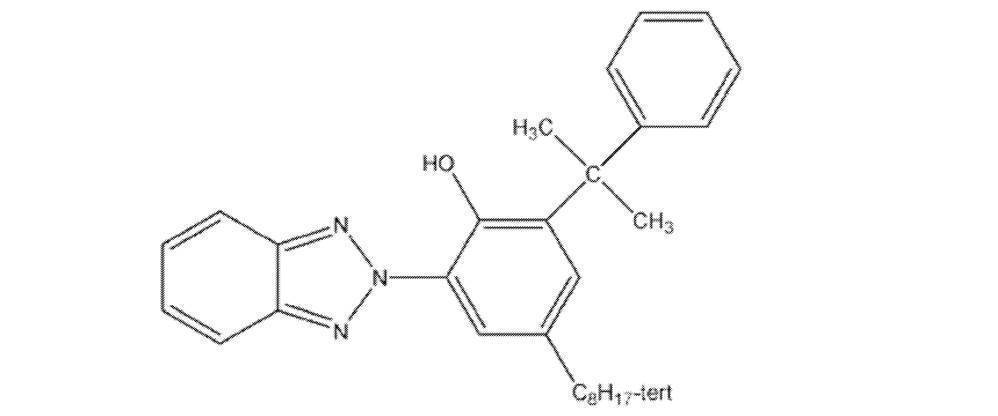
上記コア層セルロースアシレート溶液90質量部に下記「マット剤溶液の成分」からなるマット剤溶液を10質量部加え、外層セルロースアセテート溶液を調製した。
・平均粒子サイズ20nmのシリカ粒子(AEROSIL R972、日本アエロジル社製)(2質量部)
・メチレンクロライド(第1溶媒)(76質量部)
・メタノール(第2溶剤)(11質量部)
・上記コア層セルロースアシレートドープ(1質量部)
上記コア層セルロースアシレート溶液とその両側に外層セルロースアシレート溶液とを3層同時に流延口から20℃のドラム上に流延した。溶剤含有率略20質量%の状態で剥ぎ取り、フィルムの幅方向の両端をテンタークリップで固定し、残留溶剤が3~15%の状態で、横方向に1.1倍延伸しつつ乾燥した。その後、熱処理装置のロール間を搬送することにより、さらに乾燥し、厚さ40μmのセルロースアシレートフィルムを作製した(保護膜5)。また、流延量を調整し、厚さ25μm(保護膜4)と5μm(保護膜3)のセルロースアシレートフィルムを作製した。保護膜3~5について横方向の弾性率を測定したところ、5.7GPaであった。
また、流延量、延伸条件を適宜変更することにより、厚さ25μmかつ横方向の弾性率2.7GPaかつ湿度寸法変化0.2%のセルロースアシレートフィルム(保護膜1)、厚さ25μmかつ横方向の弾性率2.7GPaかつ湿度寸法変化0.0%のセルロースアシレートフィルム(保護膜7)、厚さ25μmかつ横方向の弾性率8.7GPaかつ湿度寸法変化0.2%のセルロースアシレートフィルム(保護膜6)、厚さ25μmかつ横方向の弾性率8.7GPaかつ湿度寸法変化0.4%のセルロースアシレートフィルム(保護膜8)も作製した。
なお、上述の横方向の弾性率は、後述する<耐カール性の評価>におけるカールが大きい方向の弾性率に相当する。
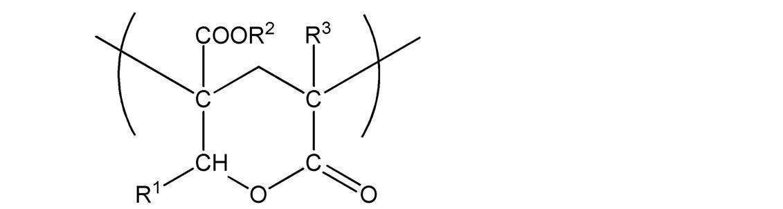
下記式(I)(ここで、R1は水素原子、R2およびR3はメチル基を表す)で表されるラクトン環構造を有する(メタ)アクリル系樹脂{共重合モノマー質量比=メタクリル酸メチル/2-(ヒドロキシメチル)アクリル酸メチル=8/2、ラクトン環化率約100%、ラクトン環構造の含有割合19.4%、質量平均分子量133000、メルトフローレート6.5g/10分(240℃、10kgf)、Tg131℃}90質量部と、アクリロニトリル-スチレン(AS)樹脂{トーヨーAS AS20、東洋スチレン社製}10質量部との混合物(Tg:127℃)のペレットを二軸押し出し機に供給し、約280℃でシート状に溶融押し出しして、厚さ110μmのラクトン環構造を有する(メタ)アクリル系樹脂シートを得た。この未延伸シートを、160℃の温度条件下、縦2.0倍、横2.4倍に延伸してアクリルフィルム(厚さ:20μm、弾性率:3.3GPa)を得た。得られたアクリルフィルムを保護膜2とする。
特許第4804588号公報に記載の方法に従い、薄膜の偏光子を以下の通り作製した。具体的には、まず、イソフタル酸を6mol%共重合させたイソフタル酸共重合ポリエチレンテレフタレートを、非晶性エステル系熱可塑性樹脂基材として準備した。この樹脂基材上に、塗布によりPVA系樹脂層を形成した。樹脂基材とPVA系樹脂層とを一体に、空中補助延伸とホウ酸水中延伸とからなる2段延伸工程で延伸し、PVA系樹脂層に二色性色素による染色処理を施した後、非晶性エステル系熱可塑性樹脂基材を剥離することにより、偏光子を作製した。得られた偏光子を偏光子1とする。偏光子1の厚みは5.0μmであった。また、弾性率は6.8GPaであった。弾性率の評価方法は上述のとおりである。
ポリビニルアルコールフィルムを40℃の温水中で約6倍に延伸した。これを、ヨウ素0.5g/l、ヨウ化カリウム50g/lの水溶液中に30℃にて1分間浸漬した。次いでホウ酸100g/l、ヨウ化カリウム60g/lの水溶液中に70℃にて5分間浸漬した。さらに、水洗槽で20℃、10秒間水洗して、80℃で5分間乾燥してヨウ素系偏光子を得た。得られたヨウ素系偏光子を偏光子2とする。偏光子2の厚みは15.0μmであった。また、弾性率は6.8GPaであった。弾性率の評価方法は上述のとおりである。
使用するポリビニルアルコールフィルムの厚みを変更した以外は偏光子2と同様の手順に従って、ヨウ素系偏光子を得た。得られたヨウ素系偏光子を偏光子3とする。偏光子3の厚みは30.0μmであった。また、弾性率は6.8GPaであった。弾性率の評価方法は上述のとおりである。
ブチルアクリレート96.5質量部、アクリル酸3質量部、2-ヒドロキシエチルアクリレート0.5質量部、2,2’-アゾビスイソブチロニトリル0.15質量部、および、酢酸エチル100質量部を投入し、十分に窒素置換した後、窒素気流下で撹拌しながら、60℃で8時間反応して、重量平均分子量165万のアクリル系ポリマー溶液を得た。上記アクリル系ポリマー溶液の固形分100質量部に対して、イソシアネート系架橋剤(日本ポリウレタン(株)製,コロネートL)0.5質量部を配合し、粘着剤塗工液(固形分12%)を調製した。
保護膜3(セルロースアシレートフィルム、厚み:5.0μm、弾性率:5.7GPa)の一方の主面に、ポリビニルアルコール系接着剤を用いて、上記偏光子1を貼り付けた。
次に、上記で作製した剥離フィルム8(PETフィルム、厚み:60.0μm、弾性率:5.2GPa)の上に、上記で得られた粘着剤塗工液を、乾燥厚さが20μmになるように、ダイコータにより塗工した後、70℃のオーブン中にて、風速14m/秒の風を1分間送ることにより第1乾燥工程を施した。次いで、温度155℃、風速15m/秒の風を2分間送ることにより第2乾燥工程を施して、粘着層を形成した。
次に、粘着層の剥離フィルム8とは反対の面と、上述のとおり偏光子1を貼り付けた保護膜3の偏光子1とは反対の面とを貼りあわせた。このようにして、偏光子と保護膜と粘着層と剥離フィルムとをこの順に備える偏光板を得た。
偏光子1の代わり第1表に示される偏光子(第1表中、丸印が付されたもの)を使用し、保護膜3の代わりに第1表に示される保護膜(第1表中、丸印が付されたもの)を使用し、剥離フィルム8の代わりに第1表に示される剥離フィルム(第1表中、丸印が付されたもの)を使用した以外は実施例1と同様の手順に従って、偏光子と保護膜と粘着層と剥離フィルムとをこの順に備える偏光板を得た。
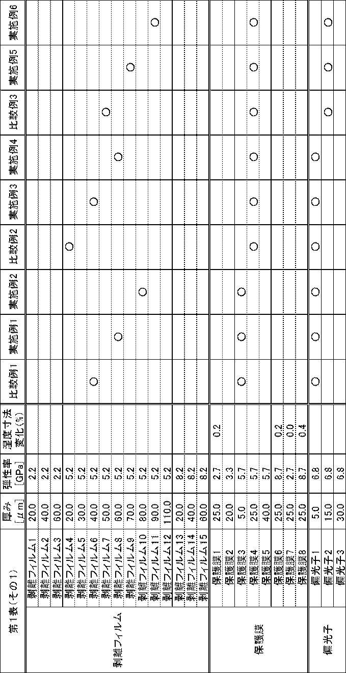

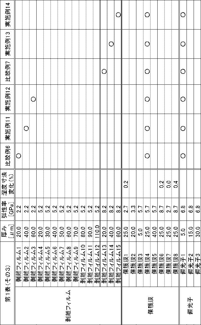


第1表に記載の保護膜1~8は、上述のとおり作製した保護膜1~8を表す。なお、保護膜1の湿度寸法変化は0.2%であり、保護膜6の湿度寸法変化は0.2%であり、保護膜7の湿度寸法変化は0.0%であり、保護膜8の湿度寸法変化は0.4%である。ここで、湿度寸法変化はカールの発生している向きの湿度寸法変化である。
第1表に記載の偏光子1~3は、上述のとおり作製した偏光子1~3を表す。
カール性の評価について、以下に説明する。まず、得られた偏光板の吸収軸方向(MD方向)と透過軸方向(TD方向)が対角線となるような、1辺10cmの正方形を打ち抜き、評価用サンプルを準備する。次に、打ち抜いた評価用サンプルを25℃相対湿度60%にて2日間調湿し、カールの曲率半径x(cm)を測定、その後25℃相対湿度40%にて2日間調湿し、カールの曲率半径y(cm)を測定する。この時、MD、TD方向どちらにもカールする可能性があるが、カールの大きい方向の曲率半径をx、yとする。また、剥離フィルムが内側のカールの時は曲率半径の符号を正、逆のカールの時は曲率半径の符号を負とする。ここで、カールの強さは、曲率半径の逆数で比較可能であり、液晶セルなどの被着体に貼合する際に貼合不良が生じないためには、貼合時の25℃相対湿度40%~25℃相対湿度60%において変化が小さいことが重要である。そこで下記式からカール値を求め、以下の評価基準で耐カール性を評価した。結果を第2表に示す。実用上、AまたはBであることが好ましく、Aであることがより好ましい。
カール値=10/y - 10/x
・D:-3.0未満または3.0超
・C:-3.0以上-2.5未満または2.5超3.0以下
・B:-2.5以上-2.0未満または2.0超2.5以下
・A:-2.0以上2.0以下
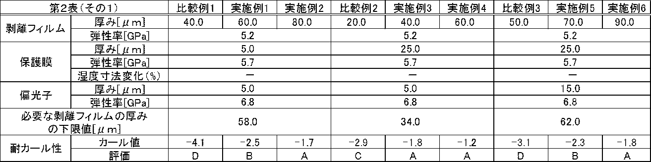
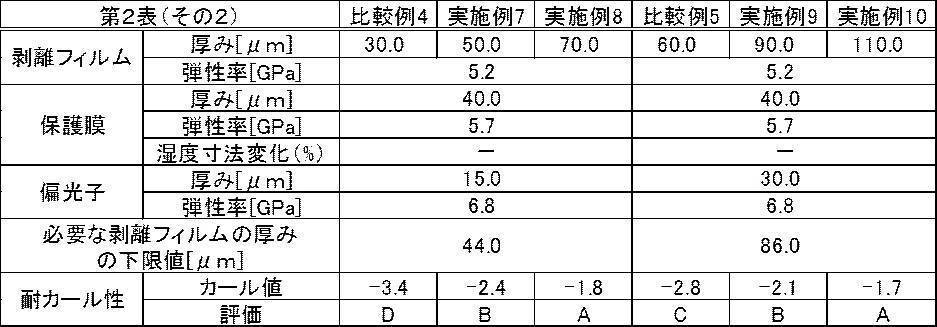


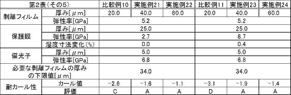
実施例3と4との対比、実施例11と12との対比、実施例13と14との対比、実施例15と16との対比、実施例17と18との対比、実施例21と22との対比、および、実施例23と24との対比から、剥離フィルムの厚みが50.0μm以上である実施例4、12、14、16、18、22および24の方がより優れた耐カール性を示した。
また、実施例3と11と13との対比、および、実施例4と12と14との対比から、剥離のフィルムの弾性率が3.0GPa以上である実施例3、4、13および14の方がより優れた耐カール性を示した。なかでも、剥離のフィルムの弾性率が6.0GPa以上である実施例13および14はさらに優れた耐カール性を示した。
また、実施例15と17との対比、および、実施例16と18との対比から、保護膜の弾性率が3.0GPa以上である実施例17および18の方がより優れた耐カール性を示した。
また、実施例21と23との対比、および、実施例22と24との対比から、保護膜の湿度寸法変化が0.2%以下である実施例21および22の方がより優れた耐カール性を示した。
また、実施例1と4との対比から、保護膜の厚みが10.0μm以上である実施例4の方がより優れた耐カール性を示した。
また、実施例5と8との対比から、保護膜の厚みが30.0μm以上である実施例8の方がより優れた耐カール性を示した。
また、実施例4と5との対比から、偏光子の厚みが10.0μm以下である実施例4の方がより優れた耐カール性を示した。
また、実施例8と9との対比から、偏光子の厚みが20.0μm以下である実施例8の方がより優れた耐カール性を示した。
上述のとおり製造した実施例1~24および比較例1~11の各偏光板について、偏光子の保護膜が貼り付けられた主面とは反対の主面に液晶層を形成し、液晶層と偏光子と保護膜と粘着層と剥離フィルムとをこの順に備える偏光板を製造した。得られた偏光板について耐カール性を評価したところ、第2表と同様の結果が得られた。
20 保護膜
30 剥離フィルム
40、42 粘着層
50、52 ハードコート層
60 液晶層
70 液晶セル
100、110、120、130、140 偏光板
200 剥離フィルムおよび粘着層が剥離される前の液晶表示装置
210 剥離フィルムおよび粘着層が剥離された後の液晶表示装置
Claims (5)
- 偏光子と保護膜と剥離フィルムとをこの順に備える偏光板であって、
前記剥離フィルムの弾性率が、2.0GPa以上であり、
前記偏光子の厚みP[μm]と前記保護膜の厚みQ[μm]と前記剥離フィルムの厚みT[μm]とが、下記式(A)を満たす、偏光板。
T≧(2.8×P-1.2×Q)+50・・・式(A) - 前記剥離フィルムの弾性率が、3.0GPa以上である、請求項1に記載の偏光板。
- さらに、液晶層を備える偏光板であって、
前記液晶層と前記偏光子と前記保護膜と前記剥離フィルムとをこの順に備える、請求項1または2に記載の偏光板。 - 請求項1~3のいずれか1項に記載の偏光板と、表示素子とを有する、画像表示装置。
- 請求項1~3のいずれか1項に記載の偏光板と、液晶セルとを備える、液晶表示装置。
Priority Applications (4)
| Application Number | Priority Date | Filing Date | Title |
|---|---|---|---|
| JP2016511883A JPWO2015152157A1 (ja) | 2014-03-31 | 2015-03-30 | 偏光板、画像表示装置および液晶表示装置 |
| KR1020167028513A KR20160134749A (ko) | 2014-03-31 | 2015-03-30 | 편광판, 화상 표시 장치 및 액정 표시 장치 |
| CN201580018190.2A CN106164720B (zh) | 2014-03-31 | 2015-03-30 | 偏振片、图像显示装置及液晶显示装置 |
| US15/279,812 US20170017026A1 (en) | 2014-03-31 | 2016-09-29 | Polarizing plate, image display device, and liquid crystal display device |
Applications Claiming Priority (2)
| Application Number | Priority Date | Filing Date | Title |
|---|---|---|---|
| JP2014074254 | 2014-03-31 | ||
| JP2014-074254 | 2014-03-31 |
Related Child Applications (1)
| Application Number | Title | Priority Date | Filing Date |
|---|---|---|---|
| US15/279,812 Continuation US20170017026A1 (en) | 2014-03-31 | 2016-09-29 | Polarizing plate, image display device, and liquid crystal display device |
Publications (1)
| Publication Number | Publication Date |
|---|---|
| WO2015152157A1 true WO2015152157A1 (ja) | 2015-10-08 |
Family
ID=54240480
Family Applications (1)
| Application Number | Title | Priority Date | Filing Date |
|---|---|---|---|
| PCT/JP2015/059939 Ceased WO2015152157A1 (ja) | 2014-03-31 | 2015-03-30 | 偏光板、画像表示装置および液晶表示装置 |
Country Status (6)
| Country | Link |
|---|---|
| US (1) | US20170017026A1 (ja) |
| JP (2) | JPWO2015152157A1 (ja) |
| KR (1) | KR20160134749A (ja) |
| CN (1) | CN106164720B (ja) |
| TW (1) | TW201543087A (ja) |
| WO (1) | WO2015152157A1 (ja) |
Cited By (5)
| Publication number | Priority date | Publication date | Assignee | Title |
|---|---|---|---|---|
| CN109074763A (zh) * | 2016-04-27 | 2018-12-21 | 日本瑞翁株式会社 | 膜传感器构件及其制造方法、圆偏振片及其制造方法、以及图像显示装置 |
| WO2020080171A1 (ja) * | 2018-10-15 | 2020-04-23 | 日東電工株式会社 | 位相差層付偏光板およびそれを用いた画像表示装置 |
| JP2020064290A (ja) * | 2018-10-15 | 2020-04-23 | 日東電工株式会社 | 位相差層付偏光板およびそれを用いた画像表示装置 |
| JP2021059112A (ja) * | 2019-10-07 | 2021-04-15 | 日東電工株式会社 | 印刷層付フィルム積層体、該印刷層付フィルム積層体を含む光学積層体、およびこれらを用いた画像表示装置 |
| JP2022039929A (ja) * | 2020-08-26 | 2022-03-10 | 日東電工株式会社 | 光学フィルム、光学フィルムの製造方法、光学部材および画像表示装置 |
Families Citing this family (2)
| Publication number | Priority date | Publication date | Assignee | Title |
|---|---|---|---|---|
| JP7257907B2 (ja) * | 2019-07-22 | 2023-04-14 | 日東電工株式会社 | 薄型円偏光板の製造方法 |
| KR102760603B1 (ko) * | 2020-11-12 | 2025-01-24 | 동우 화인켐 주식회사 | 편광판 및 이를 포함하는 화상표시장치 |
Citations (4)
| Publication number | Priority date | Publication date | Assignee | Title |
|---|---|---|---|---|
| JPH0643322A (ja) * | 1992-07-27 | 1994-02-18 | Hitachi Ltd | 粘着偏光板 |
| JP2005326531A (ja) * | 2004-05-13 | 2005-11-24 | Nitto Denko Corp | 保護フィルム付き偏光板、その製造方法及びそれを用いた画像表示装置 |
| JP2009258294A (ja) * | 2008-04-15 | 2009-11-05 | Nitto Denko Corp | 光学フィルム用粘着剤組成物、粘着型光学フィルムおよび画像表示装置 |
| JP2010229342A (ja) * | 2009-03-27 | 2010-10-14 | Lintec Corp | 光学用粘着剤、光学用粘着シート及び粘着剤付き光学部材 |
Family Cites Families (13)
| Publication number | Priority date | Publication date | Assignee | Title |
|---|---|---|---|---|
| JPH09193305A (ja) * | 1996-01-23 | 1997-07-29 | Kureha Chem Ind Co Ltd | 積層フィルム及び電子部品用包装袋 |
| JP3165100B2 (ja) * | 1998-02-09 | 2001-05-14 | 日本電気株式会社 | 液晶表示装置とその製造方法 |
| JP3818451B2 (ja) * | 2004-11-22 | 2006-09-06 | 日東電工株式会社 | 積層体の切断方法 |
| JPWO2007102327A1 (ja) * | 2006-03-08 | 2009-07-23 | コニカミノルタオプト株式会社 | 偏光板及び液晶表示装置 |
| JP2008203400A (ja) * | 2007-02-19 | 2008-09-04 | Nitto Denko Corp | 表面保護フィルム付偏光板、表面保護フィルム付液晶パネル、および画像表示装置 |
| JP2009229956A (ja) * | 2008-03-25 | 2009-10-08 | Fujifilm Corp | 帯電防止型偏光板、及び液晶表示装置 |
| JP5493523B2 (ja) * | 2009-07-10 | 2014-05-14 | 東洋紡株式会社 | 粘着シート離型用積層フィルム |
| JP4774121B2 (ja) * | 2010-01-29 | 2011-09-14 | ダイセル化学工業株式会社 | 位相差フィルム用セルロースジアセテート |
| JP5727844B2 (ja) | 2010-06-04 | 2015-06-03 | 富士フイルム株式会社 | 偏光板および液晶表示装置 |
| US8836879B2 (en) * | 2010-06-10 | 2014-09-16 | Apple Inc. | Displays with minimized curtain mura |
| US20120327510A1 (en) * | 2011-06-23 | 2012-12-27 | Nitto Denko Corporation | Polarizing plate having pressure-sensitive adhesive layer and image display device |
| KR101978721B1 (ko) * | 2012-10-08 | 2019-05-16 | 삼성디스플레이 주식회사 | 편광판, 액정 표시 장치 및 이를 제조하는 방법 |
| JP2016027354A (ja) * | 2013-07-19 | 2016-02-18 | 富士フイルム株式会社 | 偏光板用積層体、これを含む偏光板および液晶表示装置 |
-
2015
- 2015-03-30 KR KR1020167028513A patent/KR20160134749A/ko not_active Ceased
- 2015-03-30 CN CN201580018190.2A patent/CN106164720B/zh active Active
- 2015-03-30 JP JP2016511883A patent/JPWO2015152157A1/ja active Pending
- 2015-03-30 WO PCT/JP2015/059939 patent/WO2015152157A1/ja not_active Ceased
- 2015-03-31 TW TW104110382A patent/TW201543087A/zh unknown
-
2016
- 2016-09-29 US US15/279,812 patent/US20170017026A1/en not_active Abandoned
-
2018
- 2018-01-11 JP JP2018002472A patent/JP2018077522A/ja active Pending
Patent Citations (4)
| Publication number | Priority date | Publication date | Assignee | Title |
|---|---|---|---|---|
| JPH0643322A (ja) * | 1992-07-27 | 1994-02-18 | Hitachi Ltd | 粘着偏光板 |
| JP2005326531A (ja) * | 2004-05-13 | 2005-11-24 | Nitto Denko Corp | 保護フィルム付き偏光板、その製造方法及びそれを用いた画像表示装置 |
| JP2009258294A (ja) * | 2008-04-15 | 2009-11-05 | Nitto Denko Corp | 光学フィルム用粘着剤組成物、粘着型光学フィルムおよび画像表示装置 |
| JP2010229342A (ja) * | 2009-03-27 | 2010-10-14 | Lintec Corp | 光学用粘着剤、光学用粘着シート及び粘着剤付き光学部材 |
Cited By (7)
| Publication number | Priority date | Publication date | Assignee | Title |
|---|---|---|---|---|
| CN109074763A (zh) * | 2016-04-27 | 2018-12-21 | 日本瑞翁株式会社 | 膜传感器构件及其制造方法、圆偏振片及其制造方法、以及图像显示装置 |
| CN109074763B (zh) * | 2016-04-27 | 2021-06-15 | 日本瑞翁株式会社 | 膜传感器构件及其制造方法、圆偏振片及其制造方法、以及图像显示装置 |
| WO2020080171A1 (ja) * | 2018-10-15 | 2020-04-23 | 日東電工株式会社 | 位相差層付偏光板およびそれを用いた画像表示装置 |
| JP2020064290A (ja) * | 2018-10-15 | 2020-04-23 | 日東電工株式会社 | 位相差層付偏光板およびそれを用いた画像表示装置 |
| JP2021059112A (ja) * | 2019-10-07 | 2021-04-15 | 日東電工株式会社 | 印刷層付フィルム積層体、該印刷層付フィルム積層体を含む光学積層体、およびこれらを用いた画像表示装置 |
| JP2022039929A (ja) * | 2020-08-26 | 2022-03-10 | 日東電工株式会社 | 光学フィルム、光学フィルムの製造方法、光学部材および画像表示装置 |
| JP7663388B2 (ja) | 2020-08-26 | 2025-04-16 | 日東電工株式会社 | 光学フィルム、光学フィルムの製造方法、光学部材および画像表示装置 |
Also Published As
| Publication number | Publication date |
|---|---|
| JPWO2015152157A1 (ja) | 2017-04-13 |
| TW201543087A (zh) | 2015-11-16 |
| US20170017026A1 (en) | 2017-01-19 |
| JP2018077522A (ja) | 2018-05-17 |
| KR20160134749A (ko) | 2016-11-23 |
| CN106164720A (zh) | 2016-11-23 |
| CN106164720B (zh) | 2019-01-11 |
Similar Documents
| Publication | Publication Date | Title |
|---|---|---|
| JP6360821B2 (ja) | 位相差層付偏光板および画像表示装置 | |
| CN101855578B (zh) | 起偏振器的制造方法、起偏振器、偏振片、光学薄膜和图像显示装置 | |
| JP2018077522A (ja) | 偏光板、画像表示装置および液晶表示装置 | |
| TWI732231B (zh) | 偏光薄膜、附黏著劑層之偏光薄膜及影像顯示裝置 | |
| US20160209548A1 (en) | Method for manufacturing polarizing plate | |
| JP7046127B6 (ja) | 光学積層体および該光学積層体の位相差層付偏光板を含む画像表示装置 | |
| JP2003121641A (ja) | 積層位相差板、偏光部材及び液晶表示装置 | |
| WO2015046225A1 (ja) | 偏光板および画像表示装置 | |
| JP2019082719A (ja) | 偏光板 | |
| JP2013152430A (ja) | 光学フィルム、積層フィルム、及びそれらの製造方法 | |
| JP7533719B2 (ja) | 偏光板 | |
| JP2025061550A (ja) | 位相差層付偏光板および画像表示装置 | |
| JP2002365428A (ja) | 光学フィルムの製造方法及びそれを用いた積層偏光板、液晶表示装置 | |
| WO2022244301A1 (ja) | 円偏光板およびそれを用いた画像表示装置 | |
| JP2023007352A (ja) | 積層体及びその製造方法、並びに、偏光フィルムの製造方法 | |
| JP2024111076A (ja) | 積層体および画像表示パネルの製造方法 | |
| TW202001308A (zh) | 偏光薄膜、附黏著劑層之偏光薄膜及影像顯示裝置 | |
| WO2023013275A1 (ja) | 位相差層付偏光板およびそれを用いた画像表示装置 | |
| JP2003139952A (ja) | 偏光板 | |
| WO2020162298A1 (ja) | 画像表示装置およびその製造方法 | |
| KR20220058951A (ko) | 적층체, 적층체의 제조 방법, 편광판의 제조 방법 | |
| JP2009282482A (ja) | 位相差フィルム、積層体、偏光板及び画像表示装置 | |
| JP7685823B2 (ja) | 位相差層付偏光板および画像表示装置 | |
| JP4325317B2 (ja) | 光学積層体、光学素子、液晶表示装置、及び光学積層体の製造方法 | |
| JP2025184234A (ja) | 光学積層部材および光学積層体の製造方法 |
Legal Events
| Date | Code | Title | Description |
|---|---|---|---|
| 121 | Ep: the epo has been informed by wipo that ep was designated in this application |
Ref document number: 15773492 Country of ref document: EP Kind code of ref document: A1 |
|
| ENP | Entry into the national phase |
Ref document number: 2016511883 Country of ref document: JP Kind code of ref document: A |
|
| NENP | Non-entry into the national phase | ||
| ENP | Entry into the national phase |
Ref document number: 20167028513 Country of ref document: KR Kind code of ref document: A |
|
| 122 | Ep: pct application non-entry in european phase |
Ref document number: 15773492 Country of ref document: EP Kind code of ref document: A1 |