WO2015151850A1 - 燃料電池船 - Google Patents
燃料電池船 Download PDFInfo
- Publication number
- WO2015151850A1 WO2015151850A1 PCT/JP2015/058409 JP2015058409W WO2015151850A1 WO 2015151850 A1 WO2015151850 A1 WO 2015151850A1 JP 2015058409 W JP2015058409 W JP 2015058409W WO 2015151850 A1 WO2015151850 A1 WO 2015151850A1
- Authority
- WO
- WIPO (PCT)
- Prior art keywords
- fuel cell
- hull
- fuel
- fuel tank
- ship
- Prior art date
- Legal status (The legal status is an assumption and is not a legal conclusion. Google has not performed a legal analysis and makes no representation as to the accuracy of the status listed.)
- Ceased
Links
Images





Classifications
-
- B—PERFORMING OPERATIONS; TRANSPORTING
- B63—SHIPS OR OTHER WATERBORNE VESSELS; RELATED EQUIPMENT
- B63B—SHIPS OR OTHER WATERBORNE VESSELS; EQUIPMENT FOR SHIPPING
- B63B11/00—Interior subdivision of hulls
- B63B11/04—Constructional features of bunkers, e.g. structural fuel tanks, or ballast tanks, e.g. with elastic walls
-
- H—ELECTRICITY
- H01—ELECTRIC ELEMENTS
- H01M—PROCESSES OR MEANS, e.g. BATTERIES, FOR THE DIRECT CONVERSION OF CHEMICAL ENERGY INTO ELECTRICAL ENERGY
- H01M8/00—Fuel cells; Manufacture thereof
- H01M8/04—Auxiliary arrangements, e.g. for control of pressure or for circulation of fluids
- H01M8/04082—Arrangements for control of reactant parameters, e.g. pressure or concentration
- H01M8/04201—Reactant storage and supply, e.g. means for feeding, pipes
-
- B—PERFORMING OPERATIONS; TRANSPORTING
- B63—SHIPS OR OTHER WATERBORNE VESSELS; RELATED EQUIPMENT
- B63H—MARINE PROPULSION OR STEERING
- B63H21/00—Use of propulsion power plant or units on vessels
- B63H2021/003—Use of propulsion power plant or units on vessels the power plant using fuel cells for energy supply or accumulation, e.g. for buffering photovoltaic energy
-
- B—PERFORMING OPERATIONS; TRANSPORTING
- B63—SHIPS OR OTHER WATERBORNE VESSELS; RELATED EQUIPMENT
- B63J—AUXILIARIES ON VESSELS
- B63J3/00—Driving of auxiliaries
- B63J3/04—Driving of auxiliaries from power plant other than propulsion power plant
- B63J2003/046—Driving of auxiliaries from power plant other than propulsion power plant using wind or water driven turbines or impellers for power generation
-
- H—ELECTRICITY
- H01—ELECTRIC ELEMENTS
- H01M—PROCESSES OR MEANS, e.g. BATTERIES, FOR THE DIRECT CONVERSION OF CHEMICAL ENERGY INTO ELECTRICAL ENERGY
- H01M2250/00—Fuel cells for particular applications; Specific features of fuel cell system
- H01M2250/20—Fuel cells in motive systems, e.g. vehicle, ship, plane
-
- Y—GENERAL TAGGING OF NEW TECHNOLOGICAL DEVELOPMENTS; GENERAL TAGGING OF CROSS-SECTIONAL TECHNOLOGIES SPANNING OVER SEVERAL SECTIONS OF THE IPC; TECHNICAL SUBJECTS COVERED BY FORMER USPC CROSS-REFERENCE ART COLLECTIONS [XRACs] AND DIGESTS
- Y02—TECHNOLOGIES OR APPLICATIONS FOR MITIGATION OR ADAPTATION AGAINST CLIMATE CHANGE
- Y02E—REDUCTION OF GREENHOUSE GAS [GHG] EMISSIONS, RELATED TO ENERGY GENERATION, TRANSMISSION OR DISTRIBUTION
- Y02E60/00—Enabling technologies; Technologies with a potential or indirect contribution to GHG emissions mitigation
- Y02E60/30—Hydrogen technology
- Y02E60/50—Fuel cells
-
- Y—GENERAL TAGGING OF NEW TECHNOLOGICAL DEVELOPMENTS; GENERAL TAGGING OF CROSS-SECTIONAL TECHNOLOGIES SPANNING OVER SEVERAL SECTIONS OF THE IPC; TECHNICAL SUBJECTS COVERED BY FORMER USPC CROSS-REFERENCE ART COLLECTIONS [XRACs] AND DIGESTS
- Y02—TECHNOLOGIES OR APPLICATIONS FOR MITIGATION OR ADAPTATION AGAINST CLIMATE CHANGE
- Y02T—CLIMATE CHANGE MITIGATION TECHNOLOGIES RELATED TO TRANSPORTATION
- Y02T70/00—Maritime or waterways transport
-
- Y—GENERAL TAGGING OF NEW TECHNOLOGICAL DEVELOPMENTS; GENERAL TAGGING OF CROSS-SECTIONAL TECHNOLOGIES SPANNING OVER SEVERAL SECTIONS OF THE IPC; TECHNICAL SUBJECTS COVERED BY FORMER USPC CROSS-REFERENCE ART COLLECTIONS [XRACs] AND DIGESTS
- Y02—TECHNOLOGIES OR APPLICATIONS FOR MITIGATION OR ADAPTATION AGAINST CLIMATE CHANGE
- Y02T—CLIMATE CHANGE MITIGATION TECHNOLOGIES RELATED TO TRANSPORTATION
- Y02T90/00—Enabling technologies or technologies with a potential or indirect contribution to GHG emissions mitigation
- Y02T90/40—Application of hydrogen technology to transportation, e.g. using fuel cells
Definitions
- the present invention relates to a technology of a fuel cell ship that navigates using a fuel cell as a power source.
- the fuel cell ship includes a propeller that generates thrust, a motor that drives the propeller, a fuel cell that has a plurality of fuel cell stacks and generates electric power that drives the motor by reacting hydrogen and oxygen, and There is a fuel tank that stores hydrogen as a fuel (see Patent Document 1).
- the fuel cell ship In the fuel cell ship, a plurality of beams are provided on the bottom of the ship in order to increase the rigidity of the hull. However, the fuel cell ship is required to have a higher rigidity hull.
- the present invention has been made in view of the above situation, and an object of the present invention is to provide a technique capable of further increasing the rigidity of a hull in a fuel cell ship.
- the fuel cell ship navigates using a fuel cell as a power source, and includes a fuel tank that stores fuel to be supplied to the fuel cell, and the fuel tank is supported by a beam of a hull. .
- the fuel tank is arranged from the left end portion to the right end portion of the cross beam of the hull.
- the fuel tank is disposed from the bow side end to the stern side end of the longitudinal beam of the hull.
- the fuel tanks are arranged in a distributed manner.
- the following effects can be obtained. That is, according to the present invention, the rigidity of the hull can be further increased.
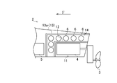
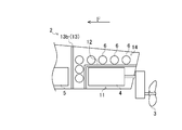
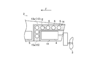
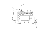
- the plane schematic diagram which shows the ship bottom of the fuel cell ship which concerns on embodiment of this invention The side surface schematic diagram which similarly shows the ship bottom of a fuel cell ship.
- the perspective view which similarly shows the ship bottom of a fuel cell ship. The block diagram of a fuel cell ship.
- the side surface schematic diagram which similarly shows the ship bottom of a fuel cell ship. The perspective view which similarly shows the ship bottom of a fuel cell ship.
- the enlarged side schematic view of the fuel cell ship An enlarged perspective view of the fuel cell ship.
- the enlarged side schematic view of the fuel cell ship. the enlarged side schematic view of the fuel cell ship.
- the enlarged side schematic view of the fuel cell ship. the enlarged side schematic view of the fuel cell ship.
- the enlarged side schematic view of the fuel cell ship. the enlarged side schematic view of the fuel cell ship.
- the fuel cell ship 1 shown in FIGS. 1 to 4 will be described.
- the black arrow F shown in the figure indicates the forward direction of the fuel cell ship 1
- the left side of the forward direction of the fuel cell ship 1 is the left side of the fuel cell ship 1 (hull 2) and the fuel.
- the right side with respect to the forward direction of the battery ship 1 will be described as the right side of the fuel cell ship 1 (hull 2).
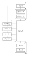
- the fuel cell ship 1 is configured to navigate using a fuel cell 5 (electric power generated by the fuel cell 5) as a power source. As shown in FIGS. 1 to 4, the fuel cell ship 1 includes a hull 2, a propeller 3, a motor 4, a fuel cell 5, a plurality of fuel tanks 6, a battery 7, a supply pipe 8, And a control device 9.
- a fuel cell 5 electric power generated by the fuel cell 5
- FIGS. 1 to 4 the fuel cell ship 1 includes a hull 2, a propeller 3, a motor 4, a fuel cell 5, a plurality of fuel tanks 6, a battery 7, a supply pipe 8, And a control device 9.
- the hull 2 of the fuel cell ship 1 is composed of a hull 2 for several passengers (for example, a small boat).
- the hull 2 can also be configured with a hull 2 for several tens of people (for example, a water bus).
- the propeller 3 of the fuel cell ship 1 generates thrust.
- the propeller 3 is disposed at the rear of the hull 2 (below the transom gate).
- the motor 4 of the fuel cell ship 1 is an electric motor and drives the propeller 3 via a marine gear.
- the motor 4 is disposed in the hull 2 (in the engine room 11 at the rear of the hull 2).
- the fuel cell 5 of the fuel cell ship 1 generates electric power by reacting hydrogen as a negative electrode active material with oxygen as a positive electrode active material taken from the air.
- the fuel cell 5 has a plurality of fuel cell stacks and generates electric power for driving the motor 4.
- the fuel cell 5 is disposed in the hull 2.
- the fuel tank 6 of the fuel cell ship 1 is a predetermined tank (container) made of a metal material, fiber reinforced plastic, or the like, and stores fuel to be supplied to the fuel cell 5.
- the fuel is hydrogen.
- the fuel tank 6 is configured in a substantially cylindrical shape.
- the fuel tank 6 is connected to a supply pipe 8 and supplies fuel to the fuel cell 5 via the supply pipe 8.
- the battery 7 of the fuel cell ship 1 is connected to the fuel cell 5 and stores the electric power generated by the fuel cell 5.
- the battery 7 is connected to the motor 4 and supplies the stored power to the motor 4.
- the battery 7 is disposed in the hull 2.
- the control device 9 of the fuel cell ship 1 is electrically connected to an operation unit 10a having a handle, a lever, and the like, and a display unit 10b having a monitor, instruments, and the like in the steering chamber of the hull 2.
- the control device 9 controls operations of the fuel cell 5, the fuel tank 6, the motor 4, and the like by operating the operation unit 10a.
- the control device 9 outputs power in the fuel cell 5, the amount of fuel supplied from the fuel tank 6 to the fuel cell 5, the remaining amount of fuel in the fuel tank 6, the remaining amount of power in the battery 7, the number of revolutions of the motor 4,
- the navigation speed is displayed on the display unit 10b.
- the hull 2 is configured by providing a plurality of beams 20 on the bottom of the ship in order to increase its rigidity.
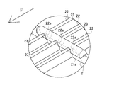
- the beam 20 includes a horizontal beam 21 and a vertical beam 22.
- the cross beam 21 is arranged so as to cross the bottom of the hull 2. They are arranged side by side in the vertical direction (head-to-tail direction) at a predetermined interval from each other.
- the vertical beam 22 is disposed so as to cut the ship bottom of the hull 2.
- the vertical beams 22 are arranged side by side in the horizontal direction (left-right direction) at predetermined intervals.
- the horizontal beam 21 and the vertical beam 22 are arranged so as to be orthogonal in a plan view.
- the fuel tank 6 of the fuel cell ship 1 is configured integrally with the beam 20.
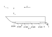
- the fuel tank 6 is fixed to the upper part of the beam 20 and supported by the beam 20.
- the rigidity of the beam 20 is further increased and the rigidity of the hull 2 is further increased. Can be increased.
- the fuel tank 6 of the fuel cell ship 1 is configured integrally with the cross beam 21.
- the fuel tank 6 is fixed to the upper part of the cross beam 21 and supported by the cross beam 21.
- the fuel tank 6 is disposed so as to overlap the horizontal beam 21 in plan view.
- the fuel tank 6 is disposed so as to be orthogonal to the longitudinal beam 22 in plan view.
- the rigidity of the cross beam 21 is further increased and the rigidity of the hull 2 is further increased. Can be increased.
- Adjacent horizontal beams 21 in the hull 2 of the fuel cell ship 1 are arranged with an interval larger than the diameter of the fuel tank 6.
- the cross beams 21 are arranged so as to be dispersed in the bow-stern direction at a predetermined interval.
- At least one transverse beam 21 is disposed on the bow side (front) of the hull 2 and at least one is disposed on the stern side (rear) of the hull 2.
- Two transverse beams 21 are arranged on the bow side of the hull 2 and two are arranged on the stern side of the hull 2.
- the horizontal beam 21 of the hull 2 of the fuel cell ship 1 is arranged at least one in at least two of the three areas obtained by equally dividing the hull 2 into the fore-and-aft direction.
- the cross beams 21 are arranged at least one by one in three regions obtained by equally dividing the hull 2 into three in the bow-stern direction.
- region A, region B, and region C the three regions obtained by dividing the hull 2 into three in the bow-stern direction will be referred to as region A, region B, and region C, respectively, in order from the bow side.
- One horizontal beam 21 is arranged in the region A.
- Two horizontal beams 21 are arranged in the region B.
- One horizontal beam 21 is arranged in the region C.
- the fuel tank 6 is disposed so that adjacent fuel tanks 6 do not contact each other. At least one fuel tank 6 is arranged in at least two of the regions A, B, and C. At least one fuel tank 6 is disposed in each of the region A, the region B, and the region C. One fuel tank 6 is arranged in the region A. Two fuel tanks 6 are arranged in the region B. One fuel tank 6 is arranged in the region C.
- the balance of the hull 2 can be improved.
- the fuel tank 6 of the fuel cell ship 1 is arranged from the left end of the cross beam 21 to the right end.
- the fuel tank 6 is disposed so as to cross a plurality of vertical beams 22 (all vertical beams 22).
- the fuel tank 6 is disposed so as to overlap with a portion where the cross beam 21 and the vertical beam 22 intersect at a plurality of locations (three locations) in plan view.
- the fuel tank 6 is disposed from the left end portion to the right end portion of the cross beam 21.
- the rigidity of the horizontal beam 21 can be further increased, and the rigidity of the hull 2 can be further increased.
- the cross beam 21 of the hull 2 of the fuel cell ship 1 has a concave portion 21a at the top thereof.
- the recess 21a of the horizontal beam 21 is configured such that the fuel tank 6 is disposed.
- the recess 21 a of the horizontal beam 21 is formed from the left end portion to the right end portion of the upper portion of the horizontal beam 21.
- the recess 21 a of the horizontal beam 21 is formed in a concave shape that matches the shape of a part of the outer surface of the fuel tank 6.
- the recess 21a of the horizontal beam 21 is formed so that its upper surface and the lower surface of the fuel tank 6 are in close contact with each other.
- the vertical beam 22 of the hull 2 of the fuel cell ship 1 has a concave portion 22a in the upper part thereof.
- the recess 22a of the vertical beam 22 is configured such that the fuel tank 6 is disposed.
- the concave portion 22 a of the vertical beam 22 is formed at a portion intersecting with the horizontal beam 21.
- the concave portion 22 a of the vertical beam 22 is formed in a concave shape that matches the shape of a part of the outer surface of the fuel tank 6.
- the recess 22a of the vertical beam 22 is formed so that its upper surface and the lower surface of the fuel tank 6 are in close contact with each other.
- the fuel tank 6 of the fuel cell ship 1 is fixed to the beam 20 so as to be fitted in the recess 21a of the cross beam 21 and the recess 22a of the vertical beam 22, and the beam 20 (the horizontal beam 21 and the vertical beam 22). Supported by
- the horizontal beam 21 has the recess 21 a, and the fuel tank 6 is supported by the horizontal beam 21 in a state of being disposed in the recess 21 a of the horizontal beam 21. While ensuring, by forming the recessed part 21a, the weight of the cross beam 21 can be reduced and the weight of the hull 2 can be reduced.
- the horizontal beam 21 and the vertical beam 22 are arranged so that a plurality of rectangular frames 23 are formed so as to be surrounded by the horizontal beam 21 and the vertical beam 22.
- the fuel cell 5 or the battery 7 is disposed in a rectangular frame 23.
- a plurality of rectangular frames 23 are formed so as to be surrounded by the horizontal beams 21 and the vertical beams 22, and the fuel cell 5 or the battery 7 is disposed in the rectangular frame 23. Then, the space in the rectangular frame 23 can be effectively used to arrange the fuel cell 5 or the battery 7 to improve the habitability in the hull 2.
- the hull 2 of the fuel cell ship 1 is configured with a plurality of beams 20 provided on the bottom of the ship in order to increase its rigidity.
- the beam 20 includes a horizontal beam 21 and a vertical beam 22.
- the fuel tank 6 of the fuel cell ship 1 is configured integrally with the longitudinal beam 22.
- the fuel tank 6 is fixed to the upper part of the vertical beam 22 and supported by the vertical beam 22.
- the fuel tank 6 is disposed so as to overlap the vertical beam 22 in plan view.
- the fuel tank 6 is disposed so as to be orthogonal to the cross beam 21 in plan view.
- the fuel tank 6 is supported by the vertical beam 22, so that the rigidity of the vertical beam 22 is further increased and the hull 2.
- the rigidity of can be further increased.
- Adjacent vertical beams 22 in the hull 2 of the fuel cell ship 1 are arranged with an interval larger than the diameter of the fuel tank 6.
- the vertical beams 22 are arranged so as to be distributed in the left-right direction at a predetermined interval.
- At least one longitudinal beam 22 is arranged on the left side of the hull 2 and at least one is arranged on the right side of the hull 2.
- One vertical beam 22 is arranged on the left side of the hull 2, one is arranged on the right side of the hull 2, and one is arranged at the center (left and right center) of the hull 2.
- the vertical beam 22 of the hull 2 of the fuel cell ship 1 is arranged at least one in at least two of the three areas obtained by equally dividing the hull 2 in the left-right direction.
- the vertical beams 22 are arranged at least one by one in three regions obtained by equally dividing the hull 2 into three in the left-right direction.
- region D the three regions obtained by dividing the hull 2 into three in the left-right direction
- region E the three regions obtained by dividing the hull 2 into three in the left-right direction
- region F region F
- One vertical beam 22 is arranged in the region D.
- One vertical beam 22 is arranged in the region E.
- One vertical beam 22 is arranged in the region F.
- the fuel tanks 6 of the fuel cell ship 1 are supported by the vertical beams 22 that are distributed in the left-right direction, and are therefore distributed in the left-right direction.
- the fuel tank 6 is disposed so that adjacent fuel tanks 6 do not contact each other.
- At least one fuel tank 6 is arranged in at least two of the regions D, E, and F.
- At least one fuel tank 6 is disposed in each of the region D, the region E, and the region F.
- One fuel tank 6 is arranged in the region D.
- One fuel tank 6 is arranged in the region E.
- One fuel tank 6 is arranged in the region F.
- the balance of the hull 2 can be improved.
- the fuel tank 6 of the fuel cell ship 1 is arranged from the bow side end of the longitudinal beam 22 to the stern side end.
- the fuel tank 6 is disposed so as to cut a plurality of transverse beams 21 (all the transverse beams 21).
- the fuel tank 6 is disposed so as to overlap with a portion where the cross beam 21 and the vertical beam 22 intersect at a plurality of locations (four locations) in plan view.
- the fuel tank 6 is disposed from the bow side end portion of the longitudinal beam 22 to the stern side. Since it arrange
- the vertical beam 22 of the hull 2 of the fuel cell ship 1 has a recess 22b in the upper part thereof.
- the recess 22b of the vertical beam 22 is configured such that the fuel tank 6 is disposed.
- the concave portion 22b of the vertical beam 22 is formed from the bow side end of the upper part of the vertical beam 22 to the stern side end.
- the concave portion 22 b of the vertical beam 22 is formed in a concave shape that matches the shape of a part of the outer surface of the fuel tank 6.
- the recess 22b of the vertical beam 22 is formed so that its upper surface and the lower surface of the fuel tank 6 are in close contact with each other.
- the cross beam 21 of the hull 2 of the fuel cell ship 1 has a recess 21b in the upper part thereof.
- the recess 21b of the horizontal beam 21 is configured such that the fuel tank 6 is disposed.
- the recess 21 b of the horizontal beam 21 is formed at a portion intersecting with the vertical beam 22.
- the concave portion 21 b of the horizontal beam 21 is formed in a concave shape that matches the shape of a part of the outer surface of the fuel tank 6.
- the recess 21b of the horizontal beam 21 is formed so that its upper surface and the lower surface of the fuel tank 6 are in close contact with each other.
- the fuel tank 6 of the fuel cell ship 1 is fixed to the beam 20 in a state of being fitted in the recess 21b of the cross beam 21 and the recess 22b of the vertical beam 22, and the beam 20 (the horizontal beam 21 and the vertical beam 22). Supported by
- the vertical beam 22 has the concave portion 22 b, and the fuel tank 6 is supported by the vertical beam 22 in a state of being disposed in the concave portion 22 b of the vertical beam 22.
- the weight of the vertical beam 22 can be reduced and the weight of the hull 2 can be reduced.
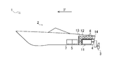
- the fuel cell ship 1 includes an engine room 11.
- the engine room 11 of the fuel cell ship 1 is disposed in the hull 2.
- the engine room 11 is arranged in the lower rear part of the hull 2.
- the engine room 11 is configured such that the motor 4 and a transmission are arranged.
- the engine room 11 is configured with the wall member 12 disposed so that a space in which the motor 4 and the like can be disposed is formed in the rear lower portion of the hull 2.
- the wall member 12 is a substantially L-shaped member having a top surface and a bow side surface, and is configured to cover the motor 4.
- the engine room 11 is configured by a space in which the motor 4 and the like inside the wall member 12 can be arranged.
- the fuel tank 6 of the fuel cell ship 1 is arranged side by side so as to cover the motor 4.
- the fuel tank 6 is disposed so as to shield a portion in the hull 2 where the motor 4 is disposed and a portion other than the portion in the hull 2 where the motor 4 is disposed.
- the fuel tank 6 is arranged so that the axial direction of the fuel tank 6 is orthogonal to (crosses) the bow-stern direction of the hull 2.
- the fuel tank 6 is arranged so that the axial direction of the fuel tank 6 is along the left-right direction of the hull 2.
- the fuel tank 6 is arranged side by side so as to cover the motor 4. It is possible to prevent the drive sound of the motor 4 from leaking to the opposite side (cabin side). Therefore, according to the fuel cell ship 1, it can be suppressed that the drive sound of the motor 4 is heard as noise in the hull 2 (in the cabin).
- the fuel tanks 6 of the fuel cell ship 1 are arranged side by side so as to cover the engine room 11 (wall member 12).
- the fuel tank 6 is arranged so as to shield the engine room 11 and a part of the hull 2 other than the part where the engine room 11 is arranged.
- the fuel tank 6 is arranged outside the wall member 12 so as to be substantially L-shaped in a side view.
- the fuel tank 6 is arranged side by side above the upper surface of the wall member 12 and is arranged side by side on the bow side of the bow side of the wall member 12.
- the fuel cell ship 1 in which the motor 4 is arranged in the engine room 11 and the fuel tank 6 is arranged so as to cover the engine room 11, the wall member 12 of the engine room 11, the fuel tank 6,
- the fuel cell ship 1 since the fuel tanks 6 are arranged so as to cover the engine room 11, sound generated when the motor 4 is driven to rotate the propeller 4 (for example, a drive shaft or the like). (Sound) can be suppressed from being heard as noise in the hull 2 (in the cabin).
- the fuel cell ship 1 includes a sound insulation member 13.
- the sound insulation member 13 performs sound insulation so that the drive sound of the motor 4 cannot be heard in the hull 2.
- the sound insulation member 13 is disposed so as to shield the portion of the hull 2 where the motor 4 and the fuel tank 6 are disposed and the portion of the hull 2 other than the portion where the motor 4 and the fuel tank 6 are disposed.
- the sound insulation member 13 includes a sound insulation cover 13a.
- the sound insulation cover 13a of the fuel cell ship 1 is a substantially L-shaped member having a top surface and a bow side surface, and has a plurality of fuel tanks 6 (fuel tanks 6 arranged side by side so as to cover the engine room 11). Configured to cover.
- the upper surface of the sound insulation cover 13 a is located above the fuel tank 6 arranged side by side above the upper surface of the wall member 12.
- the bow side surface of the sound insulation cover 13 a is located on the bow side of the fuel tank 6 arranged side by side on the bow side of the bow side surface of the wall member 12.
- a space between the inner side of the sound insulating cover 13a and the outer side of the wall member 12 constitutes a tank arrangement chamber 14 in which the fuel tank 6 is arranged.
- the fuel tank 6 is arranged inside the sound insulation cover 13a (in the tank arrangement chamber 14).
- the sound insulation member 13 and the sound insulation member 13 are separated by the fuel tank 6 (or the wall member 12 and the fuel tank 6 of the engine room 11) and the sound insulation member 13. It is possible to suppress the drive sound of the motor 4 from leaking to the fuel tank 4 on the side opposite to the motor 4 side (cabin side). Therefore, according to the fuel cell ship 1, it is possible to further suppress the driving sound of the motor 4 from being heard as noise in the hull 2 (in the cabin).
- the sound insulation member 13 of the fuel cell ship 1 can also be comprised by the sound insulation wall 13b.
- the sound insulation wall 13 b is a wall-like member and is erected so as to shield the space in the hull 2.
- the sound insulation wall 13 b is located on the bow side of the fuel tank 6 arranged side by side on the bow side of the bow side of the wall member 12.
- a space between the inside of the sound insulation wall 13b and the outside of the wall member 12 constitutes a tank arrangement chamber 14 in which the fuel tank 6 is arranged.
- the fuel tank 6 is arranged on the stern side (in the tank arrangement chamber 14) of the sound insulation wall 13b.
- the sound insulation member 13 (sound insulation cover 13a or sound insulation wall 13b) of the fuel cell ship 1 is made of fiber reinforced plastic such as glass fiber or carbon fiber, or a hard material such as a metal material.
- the sound insulating member 13 is made of a hard material, for example, even if the sound insulating member 13 is in contact with an obstacle, the inside of the sound insulating member 13 (tank arrangement chamber 14). It is possible to prevent the fuel tank 6 arranged in the inner) from being damaged.
- the fuel cell ship 1 can also include a sound absorbing member 15.
- the sound absorbing member 15 absorbs the driving sound of the motor 4.
- the sound absorbing member 15 is composed of a sound absorbing member 15a such as glass fiber (glass wool), mineral fiber (rock wool), sponge material, and the like.
- the sound absorbing member 15a is arranged in the tank arrangement chamber 14 so as to be spread.
- the sound absorbing member 15 a is disposed around the fuel tank 6 so as to surround the fuel tank 6.
- the sound absorbing member 15 prevents the drive sound of the motor 4 from leaking to the fuel tank 4 on the side opposite to the motor 4 side (cabin side). Can do. Therefore, according to the fuel cell ship 1, it is possible to further suppress the driving sound of the motor 4 from being heard as noise in the hull 2 (in the cabin).
- the sound absorbing member 15 can also be constituted by a sound absorbing member 15 b such as a sound absorbing board formed in a plate shape. At this time, the sound absorbing member 15 b is provided on the inner surface (side surface of the motor 4) of the sound insulating member 13 so as to cover the fuel tank 6.
- the present invention can be used in the technology of a fuel cell ship that navigates using a fuel cell as a power source.
Landscapes
- Chemical & Material Sciences (AREA)
- Engineering & Computer Science (AREA)
- Combustion & Propulsion (AREA)
- Mechanical Engineering (AREA)
- Ocean & Marine Engineering (AREA)
- Life Sciences & Earth Sciences (AREA)
- Manufacturing & Machinery (AREA)
- Sustainable Development (AREA)
- Sustainable Energy (AREA)
- Chemical Kinetics & Catalysis (AREA)
- Electrochemistry (AREA)
- General Chemical & Material Sciences (AREA)
- Fuel Cell (AREA)
Abstract
燃料電池を動力源として航行する燃料電池船において、船体の剛性をさらに高めることができる技術を提供することを課題とする。燃料電池(5)を動力源として航行する燃料電池船(1)であって、燃料電池(5)に供給する燃料である水素を貯留する燃料タンク(6)を備え、燃料タンク(6)は、船体(2)の梁(20)に支持されるものとする。好ましくは、燃料タンク(6)は、船体(2)の横梁(21)の左端部から右端部に亘って配置されるもの、または、燃料タンク(6)は、船体(2)の縦梁(22)の船首側端部から船尾側端部に亘って配置されるものとする。
Description
本発明は、燃料電池を動力源として航行する燃料電池船の技術に関する。
従来、燃料電池を動力源として航行する燃料電池船に関する技術は公知となっている。
前記燃料電池船には、推力を発生するプロペラと、プロペラを駆動するモータと、複数個の燃料電池スタックを有し水素と酸素とを反応させてモータを駆動する電力を発生する燃料電池と、燃料である水素を貯留する燃料タンクと、を備えるものがある(特許文献1参照)。
前記燃料電池船には、推力を発生するプロペラと、プロペラを駆動するモータと、複数個の燃料電池スタックを有し水素と酸素とを反応させてモータを駆動する電力を発生する燃料電池と、燃料である水素を貯留する燃料タンクと、を備えるものがある(特許文献1参照)。
しかしながら、前記燃料電池船では、船体の剛性を高めるために複数個の梁が船底に設けられている。もっとも、前記燃料電池船では、より高い剛性の船体とすることが求められている。
発明は以上の如き状況に鑑みてなされたものであり、燃料電池船において船体の剛性をさらに高めることができる技術を提供することを課題とする。
本発明の解決しようとする課題は以上の如くであり、次にこの課題を解決するための手段を説明する。
本発明においては、燃料電池を動力源として航行する燃料電池船であって、前記燃料電池に供給する燃料を貯留する燃料タンクを備え、前記燃料タンクは、船体の梁に支持されるものである。
本発明においては、前記燃料タンクは、前記船体の横梁の左端部から右端部に亘って配置されるものである。
本発明においては、前記燃料タンクは、前記船体の縦梁の船首側端部から船尾側端部に亘って配置されるものである。
本発明においては、前記燃料タンクは、分散して配置されるものである。
本発明の効果として、以下に示すような効果を奏する。
即ち、本発明によれば、船体の剛性をさらに高めることができる。
即ち、本発明によれば、船体の剛性をさらに高めることができる。
次に、図1から図4に記載の燃料電池船1について説明する。
なお、以下において、図中に示す黒色矢印Fは燃料電池船1の前進方向を示し、燃料電池船1の前進方向に対して左方を燃料電池船1(船体2)の左方と、燃料電池船1の前進方向に対して右方を燃料電池船1(船体2)の右方として説明する。
なお、以下において、図中に示す黒色矢印Fは燃料電池船1の前進方向を示し、燃料電池船1の前進方向に対して左方を燃料電池船1(船体2)の左方と、燃料電池船1の前進方向に対して右方を燃料電池船1(船体2)の右方として説明する。
燃料電池船1は、燃料電池5(燃料電池5で発電された電力)を動力源として航行するように構成される。
図1から図4に示すように、燃料電池船1は、船体2と、プロペラ3と、モータ4と、燃料電池5と、複数個の燃料タンク6と、バッテリ7と、供給管8と、制御装置9と、を備える。
図1から図4に示すように、燃料電池船1は、船体2と、プロペラ3と、モータ4と、燃料電池5と、複数個の燃料タンク6と、バッテリ7と、供給管8と、制御装置9と、を備える。
燃料電池船1の船体2は、数人乗用の船体2(例えば、小型ボート)で構成される。
なお、船体2は、数十人乗用の船体2(例えば、水上バス)で構成することもできる。
なお、船体2は、数十人乗用の船体2(例えば、水上バス)で構成することもできる。
燃料電池船1のプロペラ3は、推力を発生する。プロペラ3は船体2の後部(トランサムゲートの下方)に配置される。
燃料電池船1のモータ4は、電動モータであり、マリンギアを介してプロペラ3を駆動する。モータ4は、船体2内(船体2内後部の機関室11内)に配置される。
燃料電池船1の燃料電池5は、負極活物質としての水素と空気中より取り込んだ正極活物質としての酸素とを反応させて電力を発生する。燃料電池5は、複数個の燃料電池スタックを有し、モータ4を駆動する電力を発電する。燃料電池5は、船体2内に配置される。
燃料電池船1の燃料タンク6は、金属素材または繊維強化プラスチック等で構成される所定のタンク(容器)であり、燃料電池5に供給する燃料を貯留する。前記燃料は水素である。燃料タンク6は、略円柱状に構成される。燃料タンク6は、供給管8に接続され、供給管8を介して燃料を燃料電池5に供給する。
燃料電池船1のバッテリ7は、燃料電池5に接続されて、燃料電池5で発電した電力を蓄電する。バッテリ7は、モータ4に接続されて、蓄電した電力をモータ4に給電する。バッテリ7は、船体2内に配置される。
燃料電池船1の制御装置9は、船体2の操舵室の、ハンドルおよびレバー等を有する操作部10a、および、モニタおよび計器類等を有する表示部10bに、電気的に接続される。
制御装置9は、操作部10aが操作されることによって、燃料電池5、燃料タンク6、および、モータ4等の動作を制御する。制御装置9は、燃料電池5における電力の出力、燃料タンク6から燃料電池5への燃料の供給量、燃料タンク6の燃料の残量、バッテリ7の電力の残量、モータ4の回転数、および航行速度等を表示部10bに表示させる。
制御装置9は、操作部10aが操作されることによって、燃料電池5、燃料タンク6、および、モータ4等の動作を制御する。制御装置9は、燃料電池5における電力の出力、燃料タンク6から燃料電池5への燃料の供給量、燃料タンク6の燃料の残量、バッテリ7の電力の残量、モータ4の回転数、および航行速度等を表示部10bに表示させる。
船体2は、その剛性を高めるために、複数個の梁20が船底に設けられて構成される。梁20は、横梁21と縦梁22とで構成される。
横梁21は、船体2の船底を横断するように配置される。互いに所定の間隔を空けて縦方向(船首尾方向)に並べて配置される。
縦梁22は、船体2の船底を縦断するように配置される。縦梁22は、互いに所定の間隔を空けて横方向(左右方向)に並べて配置される。
横梁21と縦梁22とは、平面視で直交するように配置される。
横梁21は、船体2の船底を横断するように配置される。互いに所定の間隔を空けて縦方向(船首尾方向)に並べて配置される。
縦梁22は、船体2の船底を縦断するように配置される。縦梁22は、互いに所定の間隔を空けて横方向(左右方向)に並べて配置される。
横梁21と縦梁22とは、平面視で直交するように配置される。
燃料電池船1の燃料タンク6は、梁20と一体的に構成される。燃料タンク6は、梁20の上部に固定して設けられて、梁20に支持される。
以上のように、燃料タンク6が梁20に支持される、燃料電池船1では、燃料タンク6が梁20に支持されることから、梁20の剛性をさらに高めて、船体2の剛性をさらに高めることができる。
燃料電池船1の燃料タンク6は、横梁21と一体的に構成される。燃料タンク6は、横梁21の上部に固定して設けられて、横梁21に支持される。燃料タンク6は、横梁21と平面視で重なるように配置される。燃料タンク6は、縦梁22と平面視で直交するように配置される。
以上のように、燃料タンク6が横梁21に支持される、燃料電池船1では、燃料タンク6が横梁21に支持されることから、横梁21の剛性をさらに高めて、船体2の剛性をさらに高めることができる。
燃料電池船1の船体2における隣り合う横梁21同士は、燃料タンク6の直径よりも大きい間隔を空けて、それぞれ配置される。横梁21は、所定の間隔を空けて船首尾方向に分散するように配置される。横梁21は、船体2の船首側(前方)に少なくとも一個配置され、船体2の船尾側(後方)に少なくとも一個配置される。横梁21は、船体2の船首側に二個配置され、船体2の船尾側に二個配置される。
燃料電池船1の船体2の横梁21は、船体2を船首尾方向に均等に三分割した三個の領域のうち、少なくとも二個の領域に少なくとも一個ずつ配置される。横梁21は、船体2を船首尾方向に均等に三分割した三個の領域に、少なくとも一個ずつ配置される。以下において、便宜上、前記船体2を船首尾方向に三分割した三個の領域については、船首側から順に、領域A、領域B、領域C、とそれぞれ称する。横梁21は、領域Aに一個配置される。横梁21は、領域Bに二個配置される。横梁21は、領域Cに一個配置される。
燃料電池船1の燃料タンク6は、船首尾方向に分散して配置される横梁21に支持されることから、船首尾方向に分散して配置される。燃料タンク6は、隣り合う燃料タンク6同士が接触しないように配置される。
燃料タンク6は、領域A、領域B、および領域Cのうち、少なくとも二個の領域に少なくとも一個ずつ配置される。燃料タンク6は、領域A、領域B、および領域Cに、少なくとも一個ずつ配置される。燃料タンク6は、領域Aに一個配置される。燃料タンク6は、領域Bに二個配置される。燃料タンク6は、領域Cに一個配置される。
燃料タンク6は、領域A、領域B、および領域Cのうち、少なくとも二個の領域に少なくとも一個ずつ配置される。燃料タンク6は、領域A、領域B、および領域Cに、少なくとも一個ずつ配置される。燃料タンク6は、領域Aに一個配置される。燃料タンク6は、領域Bに二個配置される。燃料タンク6は、領域Cに一個配置される。
以上のように、燃料タンク6が分散して配置される、燃料電池船1では、重量物である燃料タンク6が分散して配置されることから、船体2のバランスを向上させることができる。
燃料電池船1の燃料タンク6は、横梁21の左端部から右端部に亘って配置される。燃料タンク6は、複数個の縦梁22(全ての縦梁22)を横断するように配置される。燃料タンク6は、横梁21と縦梁22とが交差する部分と、複数個所(三箇所)において平面視で重なるように、配置される。
以上のように、燃料タンク6が横梁21の左端部から右端部に亘って配置される、燃料電池船1では、燃料タンク6が横梁21の左端部から右端部に亘って配置されることから、横梁21の剛性をさらに高めて、船体2の剛性をさらに高めることができる。
燃料電池船1の船体2の横梁21は、その上部に凹部21aを有する。
横梁21の凹部21aは、燃料タンク6が配置されるように構成される。横梁21の凹部21aは、横梁21の上部の左端部から右端部に亘って形成される。横梁21の凹部21aは、燃料タンク6の外面の一部の形状と一致するような凹状に形成される。横梁21の凹部21aは、その上面と燃料タンク6の下面とが密着して当接するように形成される。
横梁21の凹部21aは、燃料タンク6が配置されるように構成される。横梁21の凹部21aは、横梁21の上部の左端部から右端部に亘って形成される。横梁21の凹部21aは、燃料タンク6の外面の一部の形状と一致するような凹状に形成される。横梁21の凹部21aは、その上面と燃料タンク6の下面とが密着して当接するように形成される。
燃料電池船1の船体2の縦梁22は、その上部に凹部22aを有する。
縦梁22の凹部22aは、燃料タンク6が配置されるように構成される。縦梁22の凹部22aは、横梁21と交差する部分に形成される。縦梁22の凹部22aは、燃料タンク6の外面の一部の形状と一致するような凹状に形成される。縦梁22の凹部22aは、その上面と燃料タンク6の下面とが密着して当接するように形成される。
縦梁22の凹部22aは、燃料タンク6が配置されるように構成される。縦梁22の凹部22aは、横梁21と交差する部分に形成される。縦梁22の凹部22aは、燃料タンク6の外面の一部の形状と一致するような凹状に形成される。縦梁22の凹部22aは、その上面と燃料タンク6の下面とが密着して当接するように形成される。
燃料電池船1の燃料タンク6は、横梁21の凹部21aおよび縦梁22の凹部22aに嵌め込まれるようにして配置された状態で梁20に固定されて、梁20(横梁21および縦梁22)に支持される。
以上のように、横梁21は、凹部21aを有し、燃料タンク6は、横梁21の凹部21aに配置された状態で横梁21に支持される、燃料電池船1では、燃料タンク6によって剛性を確保しつつ、凹部21aが形成されることによって横梁21の重量を軽減させて船体2の重量を軽減させることができる。
横梁21と縦梁22とは、横梁21と縦梁22とに囲まれるようにして複数個の矩形の枠23が形成されるように、配置される。
燃料電池5またはバッテリ7は、矩形の枠23内に配置される。
燃料電池5またはバッテリ7は、矩形の枠23内に配置される。
以上のように、横梁21と縦梁22とに囲まれるようにして複数個の矩形の枠23が形成され、燃料電池5またはバッテリ7が矩形の枠23内に配置される、燃料電池船1では、矩形の枠23内のスペースを有効利用して燃料電池5またはバッテリ7を配置して、船体2内居住性を高めることができる。
次に、図5から図7に記載の燃料電池船1について説明する。
なお、図5から図7に記載の燃料電池船1の説明では、図1から図4に記載の燃料電池船1と同様の構成の部分については適宜省略し、図1から図4に記載の燃料電池船1の構成と異なる部分を中心に説明する。
なお、図5から図7に記載の燃料電池船1の説明では、図1から図4に記載の燃料電池船1と同様の構成の部分については適宜省略し、図1から図4に記載の燃料電池船1の構成と異なる部分を中心に説明する。
図5から図7に示すように、燃料電池船1の船体2は、その剛性を高めるために、複数個の梁20が船底に設けられて構成される。梁20は、横梁21と縦梁22とで構成される。
燃料電池船1の燃料タンク6は、縦梁22と一体的に構成される。燃料タンク6は、縦梁22の上部に固定して設けられて、縦梁22に支持される。燃料タンク6は、縦梁22と平面視で重なるように配置される。燃料タンク6は、横梁21と平面視で直交するように配置される。
以上のように、燃料タンク6が、縦梁22に支持される、燃料電池船1では、燃料タンク6が縦梁22に支持されることから、縦梁22の剛性をさらに高めて、船体2の剛性をさらに高めることができる。
燃料電池船1の船体2における隣り合う縦梁22同士は、燃料タンク6の直径よりも大きい間隔を空けて、それぞれ配置される。縦梁22は、所定の間隔を空けて左右方向に分散するように配置される。縦梁22は、船体2の左方に少なくとも一個配置され、船体2の右方に少なくとも一個配置される。縦梁22は、船体2の左方に一個配置され、船体2の右方に一個配置され、船体2の中央(左右中央)に一個配置される。
燃料電池船1の船体2の縦梁22は、船体2を左右方向に均等に三分割した三個の領域のうち、少なくとも二個の領域に少なくとも一個ずつ配置される。縦梁22は、船体2を左右方向に均等に三分割した三個の領域に、少なくとも一個ずつ配置される。以下において、便宜上、前記船体2を左右方向に三分割した三個の領域については、左方から順に、領域D、領域E、領域F、とそれぞれ称する。縦梁22は、領域Dに一個配置される。縦梁22は、領域Eに一個配置される。縦梁22は、領域Fに一個配置される。
燃料電池船1の燃料タンク6は、左右方向に分散して配置される縦梁22に支持されることから、左右方向に分散して配置される。燃料タンク6は、隣り合う燃料タンク6同士が接触しないように配置される。
燃料タンク6は、領域D、領域E、および領域Fのうち、少なくとも二個の領域に少なくとも一個ずつ配置される。燃料タンク6は、領域D、領域E、および領域Fに、少なくとも一個ずつ配置される。燃料タンク6は、領域Dに一個配置される。燃料タンク6は、領域Eに一個配置される。燃料タンク6は、領域Fに一個配置される。
燃料タンク6は、領域D、領域E、および領域Fのうち、少なくとも二個の領域に少なくとも一個ずつ配置される。燃料タンク6は、領域D、領域E、および領域Fに、少なくとも一個ずつ配置される。燃料タンク6は、領域Dに一個配置される。燃料タンク6は、領域Eに一個配置される。燃料タンク6は、領域Fに一個配置される。
以上のように、燃料タンク6が分散して配置される、燃料電池船1では、重量物である燃料タンク6が分散して配置されることから、船体2のバランスを向上させることができる。
燃料電池船1の燃料タンク6は、縦梁22の船首側端部から船尾側端部に亘って配置される。燃料タンク6は、複数個の横梁21(全ての横梁21)を縦断するように配置される。燃料タンク6は、横梁21と縦梁22とが交差する部分と、複数個所(四箇所)において平面視で重なるように、配置される。
以上のように、燃料タンク6が縦梁22の船首側端部から船尾側端部に亘って配置される、燃料電池船1では、燃料タンク6が縦梁22の船首側端部から船尾側端部に亘って配置されることから、縦梁22の剛性をさらに高めることができる。
燃料電池船1の船体2の縦梁22は、その上部に凹部22bを有する。
縦梁22の凹部22bは、燃料タンク6が配置されるように構成される。縦梁22の凹部22bは、縦梁22の上部の船首側端部から船尾側端部に亘って形成される。縦梁22の凹部22bは、燃料タンク6の外面の一部の形状と一致するような凹状に形成される。縦梁22の凹部22bは、その上面と燃料タンク6の下面とが密着して当接するように形成される。
縦梁22の凹部22bは、燃料タンク6が配置されるように構成される。縦梁22の凹部22bは、縦梁22の上部の船首側端部から船尾側端部に亘って形成される。縦梁22の凹部22bは、燃料タンク6の外面の一部の形状と一致するような凹状に形成される。縦梁22の凹部22bは、その上面と燃料タンク6の下面とが密着して当接するように形成される。
燃料電池船1の船体2の横梁21は、その上部に凹部21bを有する。
横梁21の凹部21bは、燃料タンク6が配置されるように構成される。横梁21の凹部21bは、縦梁22と交差する部分に形成される。横梁21の凹部21bは、燃料タンク6の外面の一部の形状と一致するような凹状に形成される。横梁21の凹部21bは、その上面と燃料タンク6の下面とが密着して当接するように形成される。
横梁21の凹部21bは、燃料タンク6が配置されるように構成される。横梁21の凹部21bは、縦梁22と交差する部分に形成される。横梁21の凹部21bは、燃料タンク6の外面の一部の形状と一致するような凹状に形成される。横梁21の凹部21bは、その上面と燃料タンク6の下面とが密着して当接するように形成される。
燃料電池船1の燃料タンク6は、横梁21の凹部21bおよび縦梁22の凹部22bに嵌め込まれるようにして配置された状態で梁20に固定されて、梁20(横梁21および縦梁22)に支持される。
以上のように、縦梁22は、凹部22bを有し、燃料タンク6は、縦梁22の凹部22bに配置された状態で縦梁22に支持される、燃料電池船1では、燃料タンク6によって剛性を確保しつつ、凹部22bが形成されることによって縦梁22の重量を軽減させて船体2の重量を軽減させることができる。
次に、図8から図12及び図4に記載の燃料電池船1について説明する。
なお、図8から図12及び図4に記載の燃料電池船1の説明では、図1から図7に記載の燃料電池船1と同様の構成の部分については適宜省略し、図1から図7に記載の燃料電池船1の構成と異なる部分を中心に説明する。
なお、図8から図12及び図4に記載の燃料電池船1の説明では、図1から図7に記載の燃料電池船1と同様の構成の部分については適宜省略し、図1から図7に記載の燃料電池船1の構成と異なる部分を中心に説明する。
燃料電池船1は、機関室11を備える。燃料電池船1の機関室11は、船体2内に配置される。機関室11は、船体2の後下部に配置される。機関室11は、モータ4およびトランスミッション等が配置されるように構成される。機関室11は、モータ4等を配置可能な空間が船体2内の後下部に形成されるように、壁部材12が配置されて構成される。壁部材12は、上面と船首側面とを有する側面視略L字状の部材であり、モータ4を覆うように構成される。機関室11は、壁部材12の内側の前記モータ4等を配置可能な空間で構成される。
燃料電池船1の燃料タンク6は、モータ4を覆うように並べて配置される。燃料タンク6は、船体2内におけるモータ4が配置される部分と、船体2内におけるモータ4が配置される部分以外の部分と、を遮蔽するように配置される。
燃料タンク6は、その軸心方向が船体2の船首尾方向と直交する(交差する)ように配置される。燃料タンク6は、その軸心方向が船体2の左右方向に沿うように配置される。
燃料タンク6は、その軸心方向が船体2の船首尾方向と直交する(交差する)ように配置される。燃料タンク6は、その軸心方向が船体2の左右方向に沿うように配置される。
以上のように、燃料タンク6がモータ4を覆うように並べて配置される、燃料電池船1では、モータ4を覆うように並べて配置される燃料タンク6によって、燃料タンク6に対してモータ4側と反対側(キャビン側)にモータ4の駆動音が漏れることを抑制することができる。
したがって、燃料電池船1によれば、モータ4の駆動音が騒音として船体2内(キャビン内)に聞こえることを、抑制することができる。
したがって、燃料電池船1によれば、モータ4の駆動音が騒音として船体2内(キャビン内)に聞こえることを、抑制することができる。
燃料電池船1の燃料タンク6は、機関室11(壁部材12)を覆うように並べて配置される。燃料タンク6は、機関室11と、船体2内における機関室11が配置される部分以外の部分と、を遮蔽するように配置される。
燃料タンク6は、壁部材12の外側に側面視略L字状に並べて配置される。燃料タンク6は、壁部材12の上面の上方に並べて配置されるとともに、壁部材12の船首側面の船首側に並べて配置される。
燃料タンク6は、壁部材12の外側に側面視略L字状に並べて配置される。燃料タンク6は、壁部材12の上面の上方に並べて配置されるとともに、壁部材12の船首側面の船首側に並べて配置される。
以上のように、モータ4が機関室11内に配置され、燃料タンク6が機関室11を覆うように並べて配置される、燃料電池船1では、機関室11の壁部材12と燃料タンク6とによって、機関室11の壁部材12および燃料タンク4に対してモータ4側と反対側(キャビン側)にモータ4の駆動音が漏れることを抑制することができる。
したがって、燃料電池船1によれば、モータ4の駆動音が騒音として船体2内(キャビン内)に聞こえることを、さらに抑制することができる。
また、燃料電池船1によれば、燃料タンク6が機関室11を覆うように並べて配置されることから、モータ4が駆動してプロペラ4を回転させる際に生じる音(例えば、ドライブシャフト等の音)が騒音として船体2内(キャビン内)に聞こえることを、抑制することができる。
したがって、燃料電池船1によれば、モータ4の駆動音が騒音として船体2内(キャビン内)に聞こえることを、さらに抑制することができる。
また、燃料電池船1によれば、燃料タンク6が機関室11を覆うように並べて配置されることから、モータ4が駆動してプロペラ4を回転させる際に生じる音(例えば、ドライブシャフト等の音)が騒音として船体2内(キャビン内)に聞こえることを、抑制することができる。
燃料電池船1は、遮音部材13を備える。
遮音部材13は、モータ4の駆動音が船体2内に聞こえないように遮音する。遮音部材13は、船体2におけるモータ4および燃料タンク6が配置される部分と、船体2におけるモータ4および燃料タンク6が配置される部分以外の部分とを、遮蔽するように配置される。
遮音部材13は、遮音カバー13aで構成される。
遮音部材13は、モータ4の駆動音が船体2内に聞こえないように遮音する。遮音部材13は、船体2におけるモータ4および燃料タンク6が配置される部分と、船体2におけるモータ4および燃料タンク6が配置される部分以外の部分とを、遮蔽するように配置される。
遮音部材13は、遮音カバー13aで構成される。
燃料電池船1の遮音カバー13aは、上面と船首側面とを有する側面視略L字状の部材であり、複数個の燃料タンク6(機関室11を覆うように並べて配置される燃料タンク6)を覆うように構成される。遮音カバー13aの上面は、壁部材12の上面の上方に並べて配置される燃料タンク6の上方に位置する。遮音カバー13aの船首側面は、壁部材12の船首側面の船首側に並べて配置される燃料タンク6の船首側に位置する。
遮音カバー13aの内側と壁部材12の外側と間の空間で、燃料タンク6が配置されるタンク配置室14を構成する。
燃料タンク6は、遮音カバー13aの内側(タンク配置室14内)に配置される。
遮音カバー13aの内側と壁部材12の外側と間の空間で、燃料タンク6が配置されるタンク配置室14を構成する。
燃料タンク6は、遮音カバー13aの内側(タンク配置室14内)に配置される。
以上のように、遮音部材13(遮音カバー13a)を備える、燃料電池船1では、燃料タンク6(または機関室11の壁部材12と燃料タンク6)と遮音部材13とによって、遮音部材13および燃料タンク4に対してモータ4側と反対側(キャビン側)にモータ4の駆動音が漏れることを抑制することができる。
したがって、燃料電池船1によれば、モータ4の駆動音が騒音として船体2内(キャビン内)に聞こえることを、さらに抑制することができる。
したがって、燃料電池船1によれば、モータ4の駆動音が騒音として船体2内(キャビン内)に聞こえることを、さらに抑制することができる。
また、図11に示すように、燃料電池船1の遮音部材13は、遮音壁13bで構成することもできる。
遮音壁13bは、壁状の部材であり、船体2内の空間を遮蔽するように立設される。遮音壁13bは、壁部材12の船首側面の船首側に並べて配置される燃料タンク6の船首側に位置する。
遮音壁13bの内側と壁部材12の外側と間の空間で、燃料タンク6が配置されるタンク配置室14を構成する。
燃料タンク6は、遮音壁13bの船尾側(タンク配置室14内)に配置される。
遮音壁13bは、壁状の部材であり、船体2内の空間を遮蔽するように立設される。遮音壁13bは、壁部材12の船首側面の船首側に並べて配置される燃料タンク6の船首側に位置する。
遮音壁13bの内側と壁部材12の外側と間の空間で、燃料タンク6が配置されるタンク配置室14を構成する。
燃料タンク6は、遮音壁13bの船尾側(タンク配置室14内)に配置される。
燃料電池船1の遮音部材13(遮音カバー13aまたは遮音壁13b)は、ガラス繊維や炭素繊維等の繊維強化プラスチック、または、金属素材等の硬質素材で構成される。
以上のように、遮音部材13が硬質素材で構成される、燃料電池船1では、例えば、仮に遮音部材13が障害物に接触した場合であっても、遮音部材13の内側(タンク配置室14内)に配置される燃料タンク6が損傷することを防止することができる。
図12に示すように、燃料電池船1は、吸音部材15を備えることもできる。吸音部材15は、モータ4の駆動音を吸音する。吸音部材15は、例えば、ガラス繊維(グラスウール)、鉱物繊維(ロックウール)、スポンジ材等の吸音部材15aで構成される。吸音部材15aは、敷詰められるようにしてタンク配置室14内に配置される。吸音部材15aは、燃料タンク6を囲むようにして燃料タンク6の周りに配置される。
以上のように、吸音部材15を備える燃料電池船1では、吸音部材15によって、燃料タンク4に対してモータ4側と反対側(キャビン側)にモータ4の駆動音が漏れることを抑制することができる。
したがって、燃料電池船1によれば、モータ4の駆動音が騒音として船体2内(キャビン内)に聞こえることを、さらに抑制することができる。
また、図13に示すように、吸音部材15は、板状に形成される吸音ボード等の吸音部材15bで構成することもできる。このとき、吸音部材15bは、燃料タンク6を覆うようにして遮音部材13の内面(モータ4側面)に設けられる。
したがって、燃料電池船1によれば、モータ4の駆動音が騒音として船体2内(キャビン内)に聞こえることを、さらに抑制することができる。
また、図13に示すように、吸音部材15は、板状に形成される吸音ボード等の吸音部材15bで構成することもできる。このとき、吸音部材15bは、燃料タンク6を覆うようにして遮音部材13の内面(モータ4側面)に設けられる。
本発明は、燃料電池を動力源として航行する燃料電池船の技術に利用することができる。
1 燃料電池船
2 船体
3 プロペラ
4 モータ
5 燃料電池
6 燃料タンク
7 バッテリ
8 供給管
9 制御装置
11 機関室
12 壁部材
13 遮音部材
14 タンク配置室
20 梁
21 横梁
22 縦梁
23 矩形の枠
2 船体
3 プロペラ
4 モータ
5 燃料電池
6 燃料タンク
7 バッテリ
8 供給管
9 制御装置
11 機関室
12 壁部材
13 遮音部材
14 タンク配置室
20 梁
21 横梁
22 縦梁
23 矩形の枠
Claims (4)
- 燃料電池を動力源として航行する燃料電池船であって、
前記燃料電池に供給する燃料を貯留する燃料タンクを備え、
前記燃料タンクは、船体の梁に支持される、
燃料電池船。 - 前記燃料タンクは、前記船体の横梁の左端部から右端部に亘って配置される、
請求項1に記載の燃料電池船。 - 前記燃料タンクは、前記船体の縦梁の船首側端部から船尾側端部に亘って配置される、
請求項1に際の燃料電池船。 - 前記燃料タンクは、分散して配置される、
請求項1から請求項3のいずれか一項に記載の燃料電池船。
Applications Claiming Priority (4)
| Application Number | Priority Date | Filing Date | Title |
|---|---|---|---|
| JP2014073915A JP6162635B2 (ja) | 2014-03-31 | 2014-03-31 | 燃料電池船 |
| JP2014-073914 | 2014-03-31 | ||
| JP2014073914A JP6077487B2 (ja) | 2014-03-31 | 2014-03-31 | 燃料電池船 |
| JP2014-073915 | 2014-03-31 |
Publications (1)
| Publication Number | Publication Date |
|---|---|
| WO2015151850A1 true WO2015151850A1 (ja) | 2015-10-08 |
Family
ID=54240180
Family Applications (1)
| Application Number | Title | Priority Date | Filing Date |
|---|---|---|---|
| PCT/JP2015/058409 Ceased WO2015151850A1 (ja) | 2014-03-31 | 2015-03-20 | 燃料電池船 |
Country Status (1)
| Country | Link |
|---|---|
| WO (1) | WO2015151850A1 (ja) |
Cited By (2)
| Publication number | Priority date | Publication date | Assignee | Title |
|---|---|---|---|---|
| NO20201189A1 (en) * | 2020-10-30 | 2022-05-02 | Ic Tech As | Hydrogen fuel tank system for a ship-motor comprising improved security features |
| CN114696011A (zh) * | 2020-12-30 | 2022-07-01 | 未势能源科技有限公司 | 动力能源总成、动力能源总成装配方法及车辆 |
Citations (5)
| Publication number | Priority date | Publication date | Assignee | Title |
|---|---|---|---|---|
| JPS62225494A (ja) * | 1986-03-26 | 1987-10-03 | Yamaha Motor Co Ltd | 小型船舶の燃料タンク室の構造 |
| JPH0233798U (ja) * | 1988-08-30 | 1990-03-02 | ||
| JPH04201797A (ja) * | 1990-11-30 | 1992-07-22 | Honda Motor Co Ltd | 小型船舶 |
| JPH06191468A (ja) * | 1992-12-25 | 1994-07-12 | Yamaha Shatai Kogyo Kk | 組立式ボート |
| JP2001225794A (ja) * | 2000-02-15 | 2001-08-21 | Ishigaki Co Ltd | 電動機駆動によるウォータージェット推進艇 |
-
2015
- 2015-03-20 WO PCT/JP2015/058409 patent/WO2015151850A1/ja not_active Ceased
Patent Citations (5)
| Publication number | Priority date | Publication date | Assignee | Title |
|---|---|---|---|---|
| JPS62225494A (ja) * | 1986-03-26 | 1987-10-03 | Yamaha Motor Co Ltd | 小型船舶の燃料タンク室の構造 |
| JPH0233798U (ja) * | 1988-08-30 | 1990-03-02 | ||
| JPH04201797A (ja) * | 1990-11-30 | 1992-07-22 | Honda Motor Co Ltd | 小型船舶 |
| JPH06191468A (ja) * | 1992-12-25 | 1994-07-12 | Yamaha Shatai Kogyo Kk | 組立式ボート |
| JP2001225794A (ja) * | 2000-02-15 | 2001-08-21 | Ishigaki Co Ltd | 電動機駆動によるウォータージェット推進艇 |
Cited By (3)
| Publication number | Priority date | Publication date | Assignee | Title |
|---|---|---|---|---|
| NO20201189A1 (en) * | 2020-10-30 | 2022-05-02 | Ic Tech As | Hydrogen fuel tank system for a ship-motor comprising improved security features |
| WO2022090331A1 (en) | 2020-10-30 | 2022-05-05 | Ic Technology As | A bulkhead compartment of a ship supporting a hydrogen fuel tank wherein the bulkhead compartment comprises improved security features |
| CN114696011A (zh) * | 2020-12-30 | 2022-07-01 | 未势能源科技有限公司 | 动力能源总成、动力能源总成装配方法及车辆 |
Similar Documents
| Publication | Publication Date | Title |
|---|---|---|
| JP6077487B2 (ja) | 燃料電池船 | |
| US11643176B1 (en) | Hull assembly for a pontoon boat | |
| JP6206771B2 (ja) | 船舶 | |
| JP6327052B2 (ja) | 電動船外機 | |
| JP6097705B2 (ja) | 主プロペラ及び追加プロペラを装備する船の運航方法 | |
| JP6652434B2 (ja) | 船舶用の推進ユニット | |
| JP2013244750A (ja) | 船外機 | |
| WO2015151983A1 (ja) | 燃料電池船 | |
| JP2015196407A (ja) | 燃料電池船 | |
| JP2013052745A (ja) | 潜水艇 | |
| JP2015196409A (ja) | 燃料電池船 | |
| JP2015196408A (ja) | 燃料電池船 | |
| JP6107241B2 (ja) | 電動船外機 | |
| KR101750122B1 (ko) | 선박 | |
| JP6162635B2 (ja) | 燃料電池船 | |
| JP2015196410A (ja) | 燃料電池船 | |
| JP2024021241A (ja) | 船舶 | |
| WO2011061963A1 (ja) | 電動船 | |
| US20250050982A1 (en) | Pontoon watercraft with electrical propulsion | |
| KR20200114063A (ko) | 선박의 추진 장치 및 이를 포함하는 선박 | |
| JP2014101027A (ja) | 燃料タンク | |
| US20210362819A1 (en) | Watercraft with electric drive system | |
| JP3159586U (ja) | 船外機 | |
| JP2011213324A (ja) | 船舶の抵抗低減装置 | |
| KR20230011407A (ko) | 쌍두선 |
Legal Events
| Date | Code | Title | Description |
|---|---|---|---|
| 121 | Ep: the epo has been informed by wipo that ep was designated in this application |
Ref document number: 15774444 Country of ref document: EP Kind code of ref document: A1 |
|
| DPE1 | Request for preliminary examination filed after expiration of 19th month from priority date (pct application filed from 20040101) | ||
| NENP | Non-entry into the national phase | ||
| 122 | Ep: pct application non-entry in european phase |
Ref document number: 15774444 Country of ref document: EP Kind code of ref document: A1 |