WO2015146763A1 - 搬送治具、装填方法、および精製方法 - Google Patents
搬送治具、装填方法、および精製方法 Download PDFInfo
- Publication number
- WO2015146763A1 WO2015146763A1 PCT/JP2015/058184 JP2015058184W WO2015146763A1 WO 2015146763 A1 WO2015146763 A1 WO 2015146763A1 JP 2015058184 W JP2015058184 W JP 2015058184W WO 2015146763 A1 WO2015146763 A1 WO 2015146763A1
- Authority
- WO
- WIPO (PCT)
- Prior art keywords
- cylinder
- cylindrical
- jig
- main body
- accommodated
- Prior art date
- Legal status (The legal status is an assumption and is not a legal conclusion. Google has not performed a legal analysis and makes no representation as to the accuracy of the status listed.)
- Ceased
Links
Images

Classifications
-
- B—PERFORMING OPERATIONS; TRANSPORTING
- B01—PHYSICAL OR CHEMICAL PROCESSES OR APPARATUS IN GENERAL
- B01D—SEPARATION
- B01D7/00—Sublimation
- B01D7/02—Crystallisation directly from the vapour phase
-
- B—PERFORMING OPERATIONS; TRANSPORTING
- B01—PHYSICAL OR CHEMICAL PROCESSES OR APPARATUS IN GENERAL
- B01D—SEPARATION
- B01D3/00—Distillation or related exchange processes in which liquids are contacted with gaseous media, e.g. stripping
Definitions
- the present invention relates to a conveying jig, a loading method, and a purification method.
- an organic EL element material used in an organic electroluminescence element (hereinafter, abbreviated as an organic EL element)
- Impurities become traps for carriers (electrons and holes) or cause quenching, and the light emission intensity, light emission efficiency, and durability of the organic EL element decrease. Therefore, in order to reduce impurities, it is necessary to purify the organic EL element material with high purity.
- Patent Document 1 discloses a purification apparatus for purifying an organic material such as an organic EL element material.
- another purification device for example, there is a device that houses an inner cylinder in an outer cylinder, sublimates an organic material, and collects the organic material on the downstream side of the inner cylinder connected to the exhaust device. is there.
- An object of the present invention is to provide a transport jig and a loading method capable of improving work efficiency when transporting and loading a cylinder for collecting a vaporized organic material into a purification apparatus. is there. Another object of the present invention is to provide a purification method for purifying an organic material using the transport jig or the loading method.
- a cylindrical first cylinder for collecting the vaporized organic material has a main body that can accommodate the first cylindrical body.
- a conveyance jig accommodated in the cylindrical second cylinder of the refining device is provided.
- the cylindrical first cylinder for collecting the vaporized organic material is accommodated in the main body of the conveyance jig, and the conveyance in which the first cylinder is accommodated. And a step of inserting / removing the jig into / from the cylindrical second cylinder of the refining device.
- the cylindrical first cylinder is accommodated in the main body of the conveyance jig, and the conveyance jig that accommodates the first cylinder is formed in the cylindrical shape of the purification apparatus.
- a step of inserting the inside of the second cylinder, a step of vaporizing the organic material while leaving the transfer jig inside the second cylinder, and the vaporized organic material on the inner surface of the first cylinder And a collecting method.
- the transport jig or the loading method it is possible to improve the working efficiency when transporting and loading the cylindrical body for collecting the vaporized organic material into the purification apparatus. .
- purifies the organic material using the conveyance jig which concerns on 1 aspect of this invention, or the said loading method is provided.
- FIG. 1 is a schematic cross-sectional view of an organic material purification apparatus 1 according to the first embodiment.
- the purification device 1 includes a device main body 2 for purifying an organic material, and a vacuum pump 3 as an exhaust device for reducing the pressure inside the device main body 2.
- a vacuum pump 3 as an exhaust device for reducing the pressure inside the device main body 2.
- the apparatus main body 2 is arranged on the outside of the cylindrical first cylindrical body 21, a storage section 23 as a raw material container, a transport jig 10 that stores the first cylindrical body 21 and the storage section 23, and the transport jig 10.
- the cylindrical second cylinder 22 that accommodates the conveying jig 10 therein, and the heater 24 and the temperature adjustment heater 25 that are disposed outside the second cylinder 22 are provided. Both ends of the second cylindrical body 22 of the apparatus main body 2 are closed with a first lid portion 26 and a second lid portion 27.
- a vacuum pump 3 is connected to the apparatus body 2.
- the vacuum pump 3 is provided with a piping member via a valve 3 a, and the piping member is connected to the second lid portion 27 so as to communicate with the inside of the apparatus main body 2. Therefore, the vacuum pump 3 can exhaust the back portion of the apparatus main body 2.
- the inside of the apparatus main body 2 is preferably decompressed to 10 ⁇ 1 Pa or less, more preferably 10 ⁇ 5 Pa or less, by the vacuum pump 3.
- the organic EL element material is accommodated in the accommodating portion 23 and is vaporized inside the apparatus main body 2, and the vaporized gaseous organic EL element material moves downstream by suction of the vacuum pump 3. It is solidified or liquefied on the inner surface of the cylinder 21 and collected.
- the organic EL element material to be purified flows in the direction in which the second lid portion 27 is provided.
- one side where the first lid portion 26 of the apparatus main body 2 is arranged is the upstream side, and the other side where the second lid portion 27 of the apparatus main body 2 is arranged.
- the side may be referred to as the downstream side.
- the material of the first cylinder 21 and the second cylinder 22 is preferably made of a material that is inert to the organic EL element material. This is to prevent the organic EL element material from being decomposed or denatured such as polymerization under the purification conditions (temperature, pressure, etc.).
- the first cylinder 21 is made of stainless steel
- the second cylinder 22 is made of quartz glass.
- the first cylinder 21 has four cylindrical collection cylinders.
- the first cylinder 21 includes, in order from the upstream side, the first collection cylinder 21A, the second collection cylinder 21B, the third collection cylinder 21C, and the fourth collection cylinder 21D. Divided and connected.
- the first collection cylinder 21A, the second collection cylinder 21B, the third collection cylinder 21C, and the fourth collection cylinder 21D are arranged coaxially and accommodated in the conveying jig 10.
- the inside of the first collection cylinder 21A is the first collection chamber R1
- the inside of the second collection cylinder 21B is the second collection chamber R2
- the inside of the third collection cylinder 21C is The third collection chamber R3
- the inside of the fourth collection cylinder 21D is the fourth collection chamber R4.
- These collection chambers R1, R2, R3, and R4 are continuously formed in the horizontal direction toward the downstream side and communicate with each other.
- the collection chambers R1, R2, R3, and R4 condense the vaporized gaseous organic EL element material and collect it as a solidified or liquefied organic EL element material.
- the accommodating part 23 is accommodated in the conveying jig 10 on the upstream side of the first cylinder 21.
- the shape of the accommodating part 23 may be any shape, for example, it is formed in a dish shape having a bottom surface of a semi-cylindrical or quadrangular plate shape, and a side surface standing in an out-of-plane direction from the periphery of the bottom surface, It contains a solid organic EL element material such as powder. It is preferable that the material of the accommodating part 23 is also comprised with a material inactive with respect to an organic EL element material.
- the heater 24 is composed of an infrared heater or the like.
- the heater 24 is arranged in an annular shape on the upstream side of the apparatus body 2 and outside the second cylinder 22.
- the temperature adjustment heater 25 is configured by an infrared heater or the like.
- the temperature adjustment heater 25 is disposed downstream of the position where the heater 24 is disposed, and is disposed outside the second cylinder 22 in a tubular shape.
- the temperature adjustment heater 25 can independently adjust the temperature inside each collection chamber R1, R2, R3, R4.
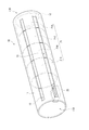
- FIG. 2 shows a perspective view of the conveying jig 10.
- the conveying jig 10 has a cylindrical main body 11.
- One first end portion 11A in the axial direction of the main body portion 11 is open, and the other second end portion 11B is provided with a collar portion 12 as a positioning means that projects in the axial direction.
- the inner diameter of the main body 11 is the same as or slightly smaller than the outer diameter of the first cylinder 21. If it is formed in such a dimension, if each collection cylinder is sequentially accommodated in the main body 11, it can be easily arranged coaxially.
- the fourth collection cylinder 21D, the third collection cylinder 21C, the second collection cylinder 21B, and the first collection cylinder 21A are accommodated sequentially from the second end portion 11B side. .
- the fourth collection cylinder 21D is in contact with the flange 12.
- the accommodating portion 23 is accommodated closer to the first end portion 11A than the first collecting cylinder 21A.
- openings 13 as position adjusting means for adjusting the position of the first cylinder 21 accommodated therein are formed at a plurality of locations.
- the opening 13 is formed in a substantially rectangular shape along the axial direction of the main body 11, but is not limited to such a shape, and may have other shapes.
- the outer side and the inner side of the main body part 11 communicate with each other through the opening part 13. Therefore, after the first cylinder 21 is accommodated in the main body 11, the position of the internal first cylinder 21 in the axial direction and the position around the axis can be adjusted through the opening 13.
- the opening part 13 can be provided in several places, and the weight reduction of the conveyance jig
- the material of the conveying jig 10 is preferably made of a material that is inert with respect to the organic EL element material, and examples thereof include quartz glass and metal.
- the conveying jig 10 is made of stainless steel.
- the organic EL device material to be purified is a material used for the organic EL device and is not particularly limited. Examples thereof include a hole transport material used for the hole transport layer, a host material used for the light emitting layer, a dopant material, and an electron transport material used for the electron transport layer.
- the loading method includes a step of accommodating the first cylinder 21 in the main body 11 of the conveying jig 10, a step of accommodating the accommodating portion 23 in the main body 11, and a first cylinder. 21 and a step of inserting the conveying jig 10 accommodating the accommodating portion 23 into the second cylindrical body 22 of the refining device 1.
- a step of pulling out the conveying jig 10 containing the first cylinder 21 and the accommodation part 23 to the outside of the second cylinder 22 is performed. In this manner, the first cylindrical body 21 and the storage portion 23 can be inserted into and extracted from the second cylindrical body 22 while the transport jig 10 stores the first cylindrical body 21 and the storage portion 23.
- the plurality of collection cylinders 21A, 21B, 21C, and 21D are sequentially accommodated as described above.
- a plurality of collecting cylinders 21A, 21B, 21C, and 21D are arranged coaxially.
- a step of adjusting the position of the accommodating portion 23 by the position adjusting means may be performed.
- the organic EL element material to be purified may be stored in the storage unit 23 in advance before being placed inside the transfer jig 10, or the organic EL element material after the placement of the storage part 23 in advance.
- the material may be accommodated, or the organic EL element material may be accommodated in the accommodating portion 23 after the transfer jig 10 is inserted into the purification apparatus 1.
- the transport jig 10 is inserted into the purification apparatus 1 by the above-described loading method.
- the 1st cover part 26 and the 2nd cover part 27 are attached, and the inside of the 2nd cylinder 22 is sealed.
- the second lid 27 may be attached in advance, the downstream side may be closed, and the conveying jig 10 may be inserted from the upstream side.
- the organic EL element material is accommodated in the accommodating portion 23 in advance.
- the inside of the second cylinder 22 is depressurized by the vacuum pump 3.
- the heater 24 and the temperature adjusting heater 25 heat the second cylinder 22 and the accommodating portion 23 and the first cylinder 21 accommodated therein. Specifically, the heater 24 heats to a temperature at which the powdered organic EL element material is vaporized (vaporization temperature) and maintains the temperature.
- the temperature adjustment heater 25 independently heats the first collection chamber R1, the second collection chamber R2, the third collection chamber R3, and the fourth collection chamber R4 to a predetermined temperature.
- the first collection chamber R1 is heated and held higher than the temperature at which the organic EL element material to be purified condenses (condensation temperature), and the second collection chamber R2 is heated to the same temperature.
- the third collection chamber R3 is heated and held slightly lower than the second collection chamber R2, and the fourth collection chamber R4 is heated and held slightly lower than the third collection chamber R3.
- the organic EL element material accommodated in the accommodating portion 23 is vaporized when the accommodating portion 23 is heated to the vaporization temperature.
- the gaseous organic EL element material moves downstream, and is collected by being solidified or liquefied on the inner surface of the first cylinder 21 corresponding to each of the collection chambers R1, R2, R3, and R4.
- each collection chamber R1, R2, R3, R4 is heated and held in the above-described relationship with respect to the condensation temperature of the organic EL element material to be purified. Therefore, the organic EL element material to be purified is collected with high purity in the second collection chamber R2 heated and held at the same temperature as the condensation temperature.
- the impurity component contained in the raw material may be collected together with the organic EL element material.
- the transport jig 10, the loading method, and the purification method according to the present embodiment have the following effects.
- the work efficiency when transporting and loading the first cylinder 21 for collecting the organic EL element material into the purification apparatus 1 is improved. Can be improved.
- the fourth collection cylinder body 21 ⁇ / b> D of the first cylinder body 21 abuts on the flange part 12.
- the collar portion 12 facilitates the axial positioning of the collection cylinders 21A, 21B, 21C, and 21D within the conveying jig 10.
- the main body 11 of the conveying jig 10 has openings 13 as a position adjusting means formed at a plurality of locations.
- the conveyance jig 10 Since the conveyance jig 10 is made of stainless steel, it is inactive with respect to the organic EL element material, and can prevent contamination of the purified organic EL element material. Moreover, since the opening part 13 is formed in multiple places in the main-body part 11 of the conveyance jig
- the main body 11 of the conveying jig 10 can accommodate a plurality of collecting cylinders 21A, 21B, 21C, and 21D in a coaxial arrangement. Therefore, the collection chambers R1, R2, R3, and R4 can be continuously connected toward the downstream side of the purification apparatus 1 to form a collection space that communicates with each other. As a result, a plurality of collection chambers individually controlled in temperature are constructed, and the organic EL element material can be efficiently collected to obtain a high-purity organic EL element material.
- the operation of accommodating the first cylinder 21 and the accommodating portion 23 by the conveying jig 10 can be performed efficiently, and the conveying jig 10 is attached to the second cylinder 22.
- the organic EL element material can be purified while being housed. As a result, the purification process can be made more efficient, and the productivity of the organic EL element material can be improved.
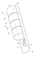
- FIG. 3 is a perspective view of the conveying jig 10A according to the present embodiment.
- 10 A of conveyance jigs have the main-body part 15 which can accommodate the 1st cylinder 21 similarly to the conveyance jig 10 of 1st embodiment.
- the main body 15 is formed in a shape obtained by dividing a cylinder into approximately halves, and has a recess 15C that is recessed in a substantially arc shape.
- the first cylinder 21 is accommodated in the recess 15C. Since the internal peripheral surface of the main-body part 15 is curving along the outer peripheral shape of the four collection cylinders 21A, 21B, 21C, and 21D, these collection cylinders can be accommodated stably.
- the main body portion 15 may be formed with an opening as position adjusting means.
- the main body 15 has one first end 15A in the longitudinal direction and the other second end 15B in the longitudinal direction.
- the second end portion 15B is provided with a collar portion 12A as positioning means for closing the second end portion 15B of the main body portion 15 in a substantially semicircular shape.
- the accommodating part 23 is accommodated on the first end part 15 ⁇ / b> A side with respect to the first cylindrical body 21 of the main body part 15 as in the first embodiment.
- the same loading method and purification method as in the first embodiment can be implemented using the transport jig 10A.
- the main body 15 has a shape obtained by dividing the cylinder into approximately half, the weight is reduced. Furthermore, it is easy to adjust the positions of the first cylinder 21 and the accommodating portion 23 accommodated in the recess 15C. Moreover, since the main body part 15 has fewer parts that block the heating from the heater 24 and the temperature adjustment heater 25 during purification than the main body part 11, the first cylindrical body 21 and the housing part 23 are more efficient. Can be heated.
- the same components as those in the first embodiment are denoted by the same reference numerals and names, and the description thereof is omitted or simplified.
- the same materials and compounds as those described in the first embodiment can be used.
- the accommodation position of the accommodating part 23 as a raw material container differs from 1st embodiment by the point which is the exterior of a conveyance jig and the inside of the 2nd cylinder 22.
- FIG. The accommodating portion 23 is placed on the inner peripheral surface of the second cylindrical body 22.
- the main body of the transport jig is cylindrical.
- the length of the main-body part of the conveyance jig in the axial direction is formed to a length that can accommodate the first cylindrical body 21. What is necessary is just to be shorter than the main-body part 11 of 1st embodiment.
- the loading method of this embodiment is implemented as follows.
- the 1st cylinder 21 is accommodated in the main-body part of the conveyance jig which concerns on this embodiment.
- the accommodating portion 23 is not accommodated in the main body portion.
- the conveyance jig in which the first cylinder 21 is accommodated is inserted into the second cylinder 22 of the purification apparatus 1.
- the accommodating portion 23 in which the organic EL element material before purification is accommodated is accommodated outside the main body portion of the conveying jig and inside the second cylindrical body 21.
- the accommodating portion 23 is accommodated on the upstream side of the apparatus main body 2 with respect to the conveying jig.
- the third embodiment is the same as the first embodiment in other points.
- the accommodating part 23 is not accommodated in the cylindrical main body part, the accommodating part 23 can be efficiently heated by the heater 24.
- the shape of the main body part of the conveying jig is not limited to the aspect described in the embodiment.
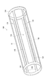
- the main body 16 of the conveying jig 10B having a shape as shown in FIG. 4 may be used.
- the main body 16 is also cylindrical, and has an annular portion 16A on each end in the axial direction, and the annular portions 16A are connected to each other by a narrow plate-like member 16B.
- the main body 16 also has a plurality of openings 13A.
- the position adjusting means is not limited to the aspect described in the above embodiment, and any means that can adjust the positions of the first cylinder and the accommodating portion accommodated in the main body portion may be used.
- the shape of the opening as the position adjusting means is not limited to the aspect described in the above embodiment, and is, for example, a rectangular shape such as a square or a rectangle, a polygon such as a triangle, a pentagon, or a hexagon, a circle, or an ellipse. An indefinite shape may be used.
- it is preferable that a plurality of holes are formed in the main body portion by punching so that the position can be adjusted and the weight of the conveying jig is reduced.
- the main body of the conveying jig is not limited to a shape obtained by dividing the cylinder into approximately half as in the second embodiment.
- a main body having a shape obtained by dividing a square tube into approximately half may be used.
- the main body may have a warp shape or a bowl shape as long as it has a recess capable of accommodating the first cylinder. It is preferable that the recessed part of this main-body part is curving along the shape of the outer periphery of a 1st cylinder.
- the loading method has been described with reference to an example in which the first cylindrical body and the accommodating portion are accommodated in advance in the conveying jig.
- the present invention is not limited to such an aspect.
- the first cylinder or the accommodation portion may be accommodated after the conveying jig is first inserted into the second cylinder.
- the first cylinder when the first cylinder is composed of a plurality of collection cylinders, the first cylinder is sequentially accommodated in the main body of the conveying jig and accommodated after the first cylinder is accommodated.
- the part can be accommodated in the main body part.
- the accommodating portion may be accommodated outside the conveying jig as in the third embodiment.
- quartz glass and stainless steel are mainly described as materials inactive to the organic EL element material, but the material is not limited to this.
- tantalum, tungsten, molybdenum, titanium, or the like can be used as the inert metal
- quartz, zirconia, alumina, boron nitride, silicon nitride, or the like can be used as the ceramic.
- carbon, polytetrafluoroethylene, or the like can be used.
- the material of the apparatus main body is not limited to the case where the whole is an inactive material with respect to the organic EL element material.
- the object to be purified is an organic material other than the organic EL element material
- a conveying jig, a first cylinder, a second cylinder, and the like are formed of a material inert to the organic material. It is preferable.
- the heating means and heating method for heating the first cylinder, the second cylinder, and the conveying jig are not limited to those described in the above embodiment.
- the heating method resistance heating method (metal type, non-metal type, etc.), light heating method (infrared heating method, arc radiation heating, laser radiation heating, etc.), induction heating method, plasma heating method, arc heating method, flame heating The law etc. can be mentioned.
- the material of the first cylinder, the second cylinder, and the conveying jig is made of a material such as stainless steel that generates heat by electromagnetic induction.
- the first cylinder is not limited to the aspect configured with the four collection cylinders and the collection chamber as described in the above embodiment. Although it depends on the size of the refining device, it is possible to obtain a higher-purity organic EL element material by increasing the number of collection cylinders and collection chambers and collecting at a higher temperature setting. . In addition, one collection cylinder and a collection chamber may be sufficient.
- a heat shield plate may be installed.
- the number of material shielding plates and heat shielding plates to be installed is not limited. For example, if a disc-shaped material shielding plate is accommodated on the second end side of the first cylindrical body in the main body portion of the conveying jig, the organic material discharged to the outside of the main body portion can be reduced.
- the heat shield plate may be accommodated on the first end side of the raw material container in the main body portion of the transfer jig, or the heat shield plate may be accommodated on the second end side of the first cylinder. May be. If the material shielding plate or the heat shielding plate is accommodated in the conveying jig, it is possible to reduce the trouble of installing and removing the shielding plate.
Landscapes
- Chemical & Material Sciences (AREA)
- Chemical Kinetics & Catalysis (AREA)
- Crystallography & Structural Chemistry (AREA)
- Vaporization, Distillation, Condensation, Sublimation, And Cold Traps (AREA)
- Electroluminescent Light Sources (AREA)
Priority Applications (2)
| Application Number | Priority Date | Filing Date | Title |
|---|---|---|---|
| KR1020167001488A KR20160137504A (ko) | 2014-03-26 | 2015-03-19 | 반송 지그, 장전 방법, 및 정제 방법 |
| CN201580001535.3A CN105473201B (zh) | 2014-03-26 | 2015-03-19 | 搬运工具、装填方法、以及提纯方法 |
Applications Claiming Priority (2)
| Application Number | Priority Date | Filing Date | Title |
|---|---|---|---|
| JP2014-064250 | 2014-03-26 | ||
| JP2014064250A JP6096144B2 (ja) | 2014-03-26 | 2014-03-26 | 搬送治具、装填方法、および精製方法 |
Publications (1)
| Publication Number | Publication Date |
|---|---|
| WO2015146763A1 true WO2015146763A1 (ja) | 2015-10-01 |
Family
ID=54195284
Family Applications (1)
| Application Number | Title | Priority Date | Filing Date |
|---|---|---|---|
| PCT/JP2015/058184 Ceased WO2015146763A1 (ja) | 2014-03-26 | 2015-03-19 | 搬送治具、装填方法、および精製方法 |
Country Status (4)
| Country | Link |
|---|---|
| JP (1) | JP6096144B2 (https=) |
| KR (1) | KR20160137504A (https=) |
| CN (1) | CN105473201B (https=) |
| WO (1) | WO2015146763A1 (https=) |
Cited By (1)
| Publication number | Priority date | Publication date | Assignee | Title |
|---|---|---|---|---|
| EP3734683A4 (en) * | 2018-09-12 | 2021-04-21 | Lg Chem, Ltd. | SUBLIMATION CLEANING DEVICE AND METHOD FOR SUBLIMATION CLEANING |
Families Citing this family (3)
| Publication number | Priority date | Publication date | Assignee | Title |
|---|---|---|---|---|
| WO2018123678A1 (ja) | 2016-12-27 | 2018-07-05 | 日本電気株式会社 | 抵抗変化素子と半導体装置および製造方法 |
| CN109257928A (zh) * | 2017-05-12 | 2019-01-22 | 出光兴产株式会社 | 有机材料的精制装置 |
| JPWO2018207763A1 (ja) * | 2017-05-12 | 2020-03-12 | 出光興産株式会社 | 有機材料の精製装置 |
Citations (6)
| Publication number | Priority date | Publication date | Assignee | Title |
|---|---|---|---|---|
| JPS58131103A (ja) * | 1981-11-07 | 1983-08-04 | ライボルト−ヘレ−ウス・ゲゼルシヤフト・ミツト・ベシユレンクテル・ハフツング | 蒸留および昇華装置 |
| JP2005511864A (ja) * | 2001-12-15 | 2005-04-28 | エスケーシー カンパニー,リミテッド | 有機電界発光材料の精製装置及び精製方法 |
| JP2005161251A (ja) * | 2003-12-04 | 2005-06-23 | Victor Co Of Japan Ltd | 有機材料の精製装置 |
| JP2011050853A (ja) * | 2009-09-01 | 2011-03-17 | Tokki Corp | 昇華精製装置 |
| JP2013208590A (ja) * | 2012-03-30 | 2013-10-10 | Idemitsu Kosan Co Ltd | 有機材料の精製装置 |
| JP2013209352A (ja) * | 2012-03-30 | 2013-10-10 | Idemitsu Kosan Co Ltd | 有機材料の精製装置 |
Family Cites Families (4)
| Publication number | Priority date | Publication date | Assignee | Title |
|---|---|---|---|---|
| JP2001323367A (ja) * | 2000-03-09 | 2001-11-22 | Junji Kido | 有機化合物の蒸着方法、及び有機化合物の精製方法 |
| JP2003095992A (ja) * | 2001-09-25 | 2003-04-03 | Sanyo Electric Co Ltd | 昇華精製方法 |
| JP4547141B2 (ja) * | 2003-10-29 | 2010-09-22 | 株式会社創造化学研究所 | 液状の媒体の回収装置 |
| JP5190194B2 (ja) * | 2005-12-02 | 2013-04-24 | 株式会社半導体エネルギー研究所 | 精製装置 |
-
2014
- 2014-03-26 JP JP2014064250A patent/JP6096144B2/ja not_active Expired - Fee Related
-
2015
- 2015-03-19 KR KR1020167001488A patent/KR20160137504A/ko not_active Ceased
- 2015-03-19 WO PCT/JP2015/058184 patent/WO2015146763A1/ja not_active Ceased
- 2015-03-19 CN CN201580001535.3A patent/CN105473201B/zh not_active Expired - Fee Related
Patent Citations (6)
| Publication number | Priority date | Publication date | Assignee | Title |
|---|---|---|---|---|
| JPS58131103A (ja) * | 1981-11-07 | 1983-08-04 | ライボルト−ヘレ−ウス・ゲゼルシヤフト・ミツト・ベシユレンクテル・ハフツング | 蒸留および昇華装置 |
| JP2005511864A (ja) * | 2001-12-15 | 2005-04-28 | エスケーシー カンパニー,リミテッド | 有機電界発光材料の精製装置及び精製方法 |
| JP2005161251A (ja) * | 2003-12-04 | 2005-06-23 | Victor Co Of Japan Ltd | 有機材料の精製装置 |
| JP2011050853A (ja) * | 2009-09-01 | 2011-03-17 | Tokki Corp | 昇華精製装置 |
| JP2013208590A (ja) * | 2012-03-30 | 2013-10-10 | Idemitsu Kosan Co Ltd | 有機材料の精製装置 |
| JP2013209352A (ja) * | 2012-03-30 | 2013-10-10 | Idemitsu Kosan Co Ltd | 有機材料の精製装置 |
Cited By (4)
| Publication number | Priority date | Publication date | Assignee | Title |
|---|---|---|---|---|
| EP3734683A4 (en) * | 2018-09-12 | 2021-04-21 | Lg Chem, Ltd. | SUBLIMATION CLEANING DEVICE AND METHOD FOR SUBLIMATION CLEANING |
| JP2021511952A (ja) * | 2018-09-12 | 2021-05-13 | エルジー・ケム・リミテッド | 昇華精製装置および昇華精製方法 |
| JP7052172B2 (ja) | 2018-09-12 | 2022-04-12 | エルジー・ケム・リミテッド | 昇華精製装置および昇華精製方法 |
| US11426678B2 (en) | 2018-09-12 | 2022-08-30 | Lg Chem, Ltd. | Sublimation purification apparatus and sublimation purification method |
Also Published As
| Publication number | Publication date |
|---|---|
| CN105473201A (zh) | 2016-04-06 |
| CN105473201B (zh) | 2018-09-28 |
| JP2015182074A (ja) | 2015-10-22 |
| KR20160137504A (ko) | 2016-11-30 |
| JP6096144B2 (ja) | 2017-03-15 |
Similar Documents
| Publication | Publication Date | Title |
|---|---|---|
| JP6096144B2 (ja) | 搬送治具、装填方法、および精製方法 | |
| JP6006516B2 (ja) | 有機材料の精製装置 | |
| US20150226485A1 (en) | System for gas purification in an induction vacuum furnace and method of making same | |
| WO2013065626A1 (ja) | 有機材料の精製装置及び有機材料の精製方法 | |
| JP5722768B2 (ja) | 金属部片を処理するためのプラズマプロセスおよび反応器 | |
| JP5585977B2 (ja) | 昇華精製装置 | |
| CN111139436A (zh) | 用于真空蒸发系统的蒸发装置、用于沉积材料膜的设备和方法 | |
| WO2005071133A3 (en) | Vacuum deposition method and sealed-type evaporation source apparatus for vacuum deposition | |
| KR101943140B1 (ko) | 유기 재료의 정제 장치 | |
| CN104383712A (zh) | 升华纯化装置 | |
| TW201338854A (zh) | 有機材料之精製裝置 | |
| JPWO2018207764A1 (ja) | 有機材料の精製装置 | |
| RU2724260C1 (ru) | Устройство для отбора повторным нагреванием для газофазного процесса | |
| KR102800267B1 (ko) | 재료 증착 장치, 진공 증착 시스템, 및 재료 증착 장치를 제조하기 위한 방법 | |
| JP2014018787A (ja) | 昇華精製回収方法および昇華精製回収装置 | |
| JP5896227B2 (ja) | 焼成炉の排ガス処理方法および装置 | |
| KR101942511B1 (ko) | 기판 처리 장치 및 기판 처리 방법 | |
| WO2018207763A1 (ja) | 有機材料の精製装置 | |
| JP2013217590A (ja) | 排ガス処理方法および排ガス処理装置 | |
| KR101142506B1 (ko) | 금속 제조장치 | |
| JP2005111303A (ja) | 昇華管及びその製造方法、並びに昇華精製装置 | |
| JP2006131931A (ja) | 蒸着方法 | |
| JP2014161743A (ja) | 昇華精製装置 | |
| JP2008073580A (ja) | 有機化合物の昇華精製装置 | |
| JP2011023256A (ja) | 蛍光ランプの製造方法 |
Legal Events
| Date | Code | Title | Description |
|---|---|---|---|
| WWE | Wipo information: entry into national phase |
Ref document number: 201580001535.3 Country of ref document: CN |
|
| 121 | Ep: the epo has been informed by wipo that ep was designated in this application |
Ref document number: 15769174 Country of ref document: EP Kind code of ref document: A1 |
|
| ENP | Entry into the national phase |
Ref document number: 20167001488 Country of ref document: KR Kind code of ref document: A |
|
| NENP | Non-entry into the national phase |
Ref country code: DE |
|
| 122 | Ep: pct application non-entry in european phase |
Ref document number: 15769174 Country of ref document: EP Kind code of ref document: A1 |