WO2015146402A1 - 炊飯器 - Google Patents
炊飯器 Download PDFInfo
- Publication number
- WO2015146402A1 WO2015146402A1 PCT/JP2015/054885 JP2015054885W WO2015146402A1 WO 2015146402 A1 WO2015146402 A1 WO 2015146402A1 JP 2015054885 W JP2015054885 W JP 2015054885W WO 2015146402 A1 WO2015146402 A1 WO 2015146402A1
- Authority
- WO
- WIPO (PCT)
- Prior art keywords
- rice cooker
- heating
- inner hook
- wire
- heat generating
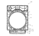
- Prior art date
- Legal status (The legal status is an assumption and is not a legal conclusion. Google has not performed a legal analysis and makes no representation as to the accuracy of the status listed.)
- Ceased
Links
Images






Classifications
-
- A—HUMAN NECESSITIES
- A47—FURNITURE; DOMESTIC ARTICLES OR APPLIANCES; COFFEE MILLS; SPICE MILLS; SUCTION CLEANERS IN GENERAL
- A47J—KITCHEN EQUIPMENT; COFFEE MILLS; SPICE MILLS; APPARATUS FOR MAKING BEVERAGES
- A47J27/00—Cooking-vessels
- A47J27/004—Cooking-vessels with integral electrical heating means
Definitions
- the present invention relates to a rice cooker.
- a container for containing rice and water Conventionally, for example, a container for containing rice and water, a protective frame that supports the container, and an upper portion of the protective frame that heats a side surface portion of the container.
- a rice cooker provided with a body heater (see, for example, Patent Document 1).
- the present invention has been made against the background of the above-described problems, and an object of the present invention is to provide a rice cooker that suppresses temperature unevenness in the inner pot as compared with the prior art.
- the rice cooker of the present invention includes an inner pot whose upper surface is open, a main body having an inner pot storage portion for storing the inner pot, and a heating means provided in the inner pot storage portion for heating the side surface of the inner pot.
- the heating means has a folded portion that is folded back so as to be provided in a plurality of stages in the vertical direction of the inner hook, and the drawing direction on one end side of the heating means is the drawing on the other end side of the heating means. The direction is opposite to the direction.
- the drawing direction on one end side of the heat generating means is opposite to the pulling direction on the other end side of the heat generating means. For this reason, the temperature nonuniformity of an inner hook can be suppressed rather than before.
- FIG. 1 is a perspective view of a rice cooker 100 according to Embodiment 1 of the present invention.
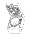
- FIG. 2 is a perspective view showing a state in which lid 10 of rice cooker 100 according to Embodiment 1 of the present invention is opened.
- 3 is an XX cross-sectional view of the rice cooker 100 of FIG. 1 (the position of the XX cross-section is a position where the lid 10 and the main body 1 are combined, and FIG. 1 is seen from above.)
- 4 is a YY cross-sectional view of the rice cooker 100 of FIG.
- FIG. 5 is a ZZ cross-sectional view of the rice cooker 100 of FIG.
- FIG. 6 is a partially enlarged view of FIG.
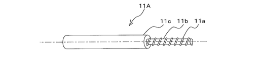
- FIG. 7 is a schematic diagram showing heater wire 11A of rice cooker 100 according to Embodiment 1 of the present invention.
- the rice cooker 100 includes a main body 1 and a lid body 10 that is attached to an upper portion of the main body 1 so as to be freely opened and closed.
- the main body 1 is provided with an inner hook storage portion 1 a.
- An inner pot 3 is stored in the inner pot storage portion 1a.
- the inner pot 3 is a member having an open top surface, and the inner pot 3 stores rice, water, and the like.
- the inner side of the inner hook 3 is made of, for example, aluminum, and the outer side of the inner hook 3 is made of, for example, a stainless material.
- the inner surface of the inner hook 3 is subjected to fluorine coating.
- a side heat dissipating plate 2 is provided on the inner wall of the inner hook accommodating portion 1 a facing the outer side of the inner hook 3.
- the side heat radiation plate 2 is formed in an annular shape so as to surround the inner hook 3.
- a sheet heating element 11 (body heater) is provided outside the side heat radiating plate 2.
- the planar heating element 11 includes a heater wire 11A, an aluminum foil 11B, and an adhesive means 11C.
- the heater wire 11A is a heat generating means including a heat generating wire 11a, a glass core 11b, and an insulator 11c.
- the heater wire 11A corresponds to the heat generating means in the present invention.
- the heating wire 11a is made of, for example, a nickel chrome wire, a copper nickel wire, or the like.
- the heating wire 11a is spirally wound around the outer surface of the glass core 11b.
- the insulator 11c is a member that covers the heating wire 11a, and is made of, for example, silicon rubber. Details of the heater wire 11A will be described with reference to FIGS.
- the aluminum foil 11B is a member that covers the heating wire 11a, and is for transmitting heat generated from the heating wire 11a to the side surface heat radiating plate 2.
- the aluminum foil 11B has been described as an example of the member that transmits the heat generated from the heating wire 11a to the side heat radiating plate 2.
- the present invention is not limited to this, and various members having good heat conductivity are employed. can do.
- the adhesion means 11C is a member for attaching the heater wire 11A and the aluminum foil 11B to the side heat radiating plate 2, and is composed of, for example, a double-sided tape.
- a heater wire 11A and an aluminum foil 11B are provided on one surface of the bonding means 11C.
- a side heat radiating plate 2 is provided on the other surface of the bonding means 11C.
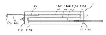
- FIG. 8 is a schematic diagram showing the planar heating element 11 of the rice cooker 100 according to Embodiment 1 of the present invention.
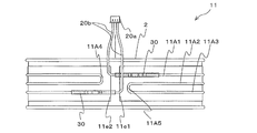
- FIG. 9 is a schematic diagram showing a state in which the planar heating element 11 of the rice cooker 100 according to Embodiment 1 of the present invention is provided on the side surface radiator plate 2. The vertical direction of the paper in FIG. 9 will be described below as the vertical direction of the side heat radiation plate 2 and the planar heating element 11.
- the planar heating element 11 is a heating means formed in, for example, a rectangular cross section, and generates heat when energized during rice cooking or heat retention.
- the heater wire 11 ⁇ / b> A extends in the longitudinal direction of the planar heating element 11 (aluminum foil 11 ⁇ / b> B) and is folded back so as to be provided in a plurality of stages in the vertical direction of the inner hook 3.
- the heater wire 11A includes extending portions 11A1, 11A2, and 11A3, and folded portions 11A4 and 11A5.
- Extension part 11A1, 11A2, 11A3 is a site
- the extending directions of the extending portions 11A1, 11A2, and 11A3 are parallel to each other.
- the folded portions 11A4 and 11A5 are portions of the heater wire 11A that are bent into, for example, a U shape.
- one end of the sheet heating element 11 in the longitudinal direction is referred to as an end part 11e1
- the other end in the longitudinal direction of the sheet heating element 11 is referred to as an end part 11e2.
- the end portion 11e1 is provided with a lead portion 11g1 through which the heater wire 11A passes.
- the end portion 11e2 is provided with a lead portion 11g2 through which the heater wire 11A passes.
- the heater wire 11A is connected to the connection member 30 at the lead portions 11g1 and 11g2.
- the connection member 30 is a member that covers a part of the heater wire 11 ⁇ / b> A, and is provided at least in the lead portions 11 g 1 and 11 g 2 of the planar heating element 11.
- the connection member 30 is formed of a hollow cylindrical member, and has an outer diameter larger than the outer diameter of the heater wire 11A, for example.
- the amount of heat generated in the portion where the heater wire 11A is covered by the connecting member 30 is smaller than the amount of heat generated in the portion where the heater wire 11A is not covered by the connecting member 30. For this reason, when the heater wire 11A generates heat, the amount of heat generated in the vicinity of the connection member 30 is smaller than in other places.
- the heater wire 11A is extended so as to form an extending portion 11A1 from the end portion 11e1 side toward the end portion 11e2 side.
- the heater wire 11A is folded so as to form the folded portion 11A4 in the vicinity of the end portion 11e2.
- the heater wire 11A is extended so as to form an extension portion 11A2 from the end portion 11e2 side toward the end portion 11e1 side.
- the heater wire 11A is folded so as to form the folded portion 11A5 in the vicinity of the end portion 11e1.
- the heater wire 11A is extended so as to form an extending portion 11A3 from the end portion 11e1 side toward the end portion 11e2 side. In this way, the heater wire 11A becomes Z-shaped. At this time, one end of the heater wire 11A is located on the end portion 11e1 side, and the other end of the heater wire 11A is located on the end portion 11e2 side. That is, the heating wire 11 a is drawn from both ends of the planar heating element 11.
- a connector 20a and a lead wire 20b are provided on both ends of the heater wire 11A.
- the connector 20a is connected to a power supply board (not shown) and the lead wire 20b.
- the lead wire 20 b is connected to the connector 20 a and the connection member 30.
- the power supply board is provided on the back side of the main body 1.
- the control means controls the amount of heat generated by the heater wire 11A. Thereby, the heat generated from the heater wire 11 ⁇ / b> A is transmitted to the inner hook 3 through the side surface heat radiating plate 2, and the object to be heated inside the inner hook 3 is heated.
- the end 11e1 and the end 11e2 are close to each other without being overlapped in a state in which the planar heating element 11 is provided on the outer side of the side heat radiating plate 2, and both ends of the heater wire 11A are Connected to the power board.
- the planar heating element 11 formed in this way is formed by forming a ring shape so that both ends are opposed to each other with the heater wire 11A facing outward.
- the connecting member 30 is located in the vicinity of the end portion 11e1.
- the calorific value near the end 11e1 is smaller than the calorific value near the end 11e2. For this reason, temperature unevenness occurs in the inner hook 3.
- the rice cooker 100 is provided in the inner pot 3 whose upper surface is opened, the main body 1 having the inner pot storage portion 1a for storing the inner pot 3, and the inner pot storage portion 1a.
- a heating wire 11a for heating the side surface of the inner hook 3, and the heating wire 11a has folded portions 11A4 and 11A5 that are folded back so as to be provided in a plurality of stages in the vertical direction of the inner hook 3.
- the drawing direction on the one end side is opposite to the drawing direction on the other end side of the heating wire 11a.
- the number of times the heater wire 11A is bent is not limited to two as shown in the figure.
- the inner hook 3 can be heated more uniformly by increasing the number of times of folding by increasing the length of the heater wire 11A.
- the heat generated from the heater wire 11A is transmitted to the inner hook 3 through the side heat radiating plate 2, the aluminum foil 11B, and the bonding means 11C, it is not limited thereto.
- the heat generated from the heater wire 11A may be directly transmitted to the inner pot 3 without providing the side heat radiating plate 2, the aluminum foil 11B, and the bonding means 11C.
- Embodiment 2 FIG. In the second embodiment, unlike the first embodiment, the number of turns of the heating wire 11a is different. In the second embodiment, items that are not particularly described are the same as those in the first embodiment, and the same functions and configurations are described using the same reference numerals.
- FIG. 10 is a schematic diagram showing the planar heating element 11 of the rice cooker 100 according to Embodiment 2 of the present invention.
- the folded portion 11A5 of the heating wire 11a is tightly wound as compared with other portions.
- the folded portion 11A4 of the heater wire 11A is tightly wound compared to other portions. That is, the heating wire 11a is configured such that the heat generation amount in the folded portions 11A4 and 11A5 of the heater wire 11A is larger than the heat generation amount in the extension portions 11A1, 11A2, and 11A3 of the heater wire 11A.
- the folded portions 11A4 and 11A5 of the heater wire 11A are densely wound compared to other portions. For this reason, the amount of heat generation can be ensured in the vicinity of the extraction portions 11g1 and 11g2 of the side surface radiator plate 2 where the amount of heat generation is low. Therefore, the temperature unevenness of the inner hook 3 can be suppressed more than before.
- the heater wire 11A is not limited to an example in which only the folded portions 11A4 and 11A5 are densely wound compared to other portions, and is located in the vicinity of the folded portion 11A4 in addition to the heating wire 11a in the folded portion 11A4.
- the heating wire 11a in the extending portions 11A1, 11A2, and 11A3 may be closely wound.
- the heater wire 11A when the heater wire 11A is folded back more, at least one folded part of all the folded parts may be tightly wound.
- the second embodiment can be applied not only to the Z-shaped heating wire 11a but also to the M-shaped heating wire 11a. Even in this case, since the heat generation amount in the vicinity of the extraction part of the heating line 11a is particularly small, the heating line 11a in the folded part located in the vicinity of the extraction parts 11g1 and 11g2 may be tightly wound. Thereby, the temperature nonuniformity of the inner hook 3 can be suppressed more than before.
- Embodiment 3 In the third embodiment, unlike the first embodiment, the number of turns of the heating wire 11a is different.
- items that are not particularly described are the same as those in Embodiment 1, and the same functions and configurations are described using the same reference numerals.
- the heating wire 11a in the extending portion 11A1 is more closely wound than the heating wire 11a in the extending portions 11A2 and 11A3.
- the number of turns of the heating wire 11a in the extension portion 11A2 and the number of turns of the heating wire 11a in the extension portion 11A3 may be the same or different.
- the heating wire 11a in the extending portion 11A1 is more closely wound than the heating wire 11a in the extending portions 11A2 and 11A3. For this reason, the opening (upper side) side in which the temperature tends to be relatively low in the inner pot 3 can be heated more strongly. Therefore, the temperature drop in the upper part of the inner hook 3 where the temperature of the inner hook 3 tends to be low can be suppressed, and the temperature unevenness of the inner hook 3 can be suppressed as compared with the conventional case.
- the heating wire 11A when the heater wire 11A is folded back more, for example, the heating wire 11a located at the uppermost stage may be tightly wound than the heating wire 11a of other portions. Even if it does in this way, the temperature nonuniformity of the inner pot 3 can be suppressed rather than before.
- the third embodiment can be applied to the M-shaped heating wire 11a. Even in this case, it is only necessary that the heating wire 11a positioned at the uppermost stage is more closely wound than the heating wires 11a of other portions. Thereby, the temperature nonuniformity of the inner hook 3 can be suppressed more than before.
- Embodiment 4 FIG.
- the distance between the extending part 11A1 and the extending part 11A2 is made smaller than the distance between the extending part 11A2 and the extending part 11A3.
- items not particularly described are the same as those in the first embodiment, and the same functions and configurations are described using the same reference numerals.
- FIG. 12 is a schematic diagram showing the planar heating element 11 of the rice cooker 100 according to Embodiment 4 of the present invention. As shown in FIG. 12, the distance d1 between the extending part 11A1 and the extending part 11A2 is shorter than the distance d2 between the extending part 11A2 and the extending part 11A3.
- the distance d1 between the extending part 11A1 and the extending part 11A2 is smaller than the distance d2 between the extending part 11A2 and the extending part 11A3. Yes. For this reason, the temperature fall in the upper part of the inner hook 3 which the temperature of the inner hook 3 tends to become low can be suppressed. Therefore, temperature uniformity can be achieved and temperature unevenness of the inner hook 3 can be suppressed as compared with the conventional case.
- the distance from the heating wire 11a located at the uppermost stage to the adjacent lower heating wire 11a is larger than the distance between the other neighboring heating wires 11a. Should be smaller. Thereby, the temperature nonuniformity of the inner hook 3 can be suppressed more than before.
- the fourth embodiment can be applied to the M-shaped heating wire 11a. Also in this case, the distance from the heating line 11a located at the uppermost stage to the adjacent lower heating line 11a only needs to be smaller than the distance between the other adjacent heating lines 11a. Thereby, the temperature nonuniformity of the inner hook 3 can be suppressed more than before.
- Embodiment 5 FIG.
- the positions of the end portions 11e1 and 11e2 of the heating wire 11a are determined in relation to the power supply substrate 20.
- items that are not particularly described are the same as those in the first embodiment, and the same functions and configurations are described using the same reference numerals.
- FIG. 13 is a cross-sectional view showing rice cooker 100 according to Embodiment 5 of the present invention (the cross-sectional position is the position of side radiator plate 2 inside main body 1 and this position is parallel to the ground plane). It is a cut figure).
- a power supply board 20 is provided inside the main body 1 and on the back side of the inner hook 3.
- the planar heating element 11 is provided along the circumferential direction of the inner hook 3
- the end portions 11 e 1 and 11 e 2 are located in the vicinity of the power supply substrate 20. That is, when the planar heating element 11 is provided along the circumferential direction of the inner hook 3, the power supply substrate 20 is located in the vicinity of the bonding portion of the planar heating element 11.
- the end portions 11e1 and 11e2 are provided on the outer side of the inner hook 3 closest to the power supply board 20 among the outer sides of the inner hook 3, for example. That is, of the heater wires 11A provided along the circumferential direction of the inner hook 3, the heater wire 11A located on the most end side and the other end side is the inner hook 3 closest to the power supply board 20 on the outer side of the inner hook 3. Is provided outside.
- both ends of the planar heating element 11 provided along the circumferential direction of the inner pot 3 are the most from the power supply board 20 in the outer side of the inner pot 3. It is provided on the outside of the nearby inner pot 3. For this reason, the distance to a connection becomes short and the workability
- edge parts 11e1 and 11e2 demonstrated the example provided in the outer side of the inner hook 3 nearest to the power supply board
- the end portions 11e 1 and 11 e 2 may be provided on the outer surface of the inner pot 3 as close as possible to the power supply board 20 on the outer side of the inner pot 3.
- 1 Main body 1a Inner pot housing part, 2 Side heat sink, 3 Inner pot, 10 Cover, 11 Planar heating element, 11A heater wire, 11A1, 11A2, 11A3 extension part, 11A4, 11A5 folded part, 11B Aluminum foil 11C bonding means, 11a heating wire (heating means), 11b glass core, 11c insulator, 11e1, 11e2 end, 11g1, 11g2 lead-out portion, 20 power supply board, 20a connector, 20b lead wire, 30 connecting member, 100 rice cooking Container, d1, d2 distance.
Landscapes
- Engineering & Computer Science (AREA)
- Food Science & Technology (AREA)
- Cookers (AREA)
- Resistance Heating (AREA)
- Surface Heating Bodies (AREA)
Abstract
上面が開口する内釜3と、内釜3を収納する内釜収納部1aを有する本体1と、内釜収納部1aに設けられ、内釜3の側面を加熱する発熱線11aと、を備え、発熱線11aは、内釜3の上下方向に複数段設けられるように折り返される折り返し部11A4,11A5を有し、発熱線11aの一端側の引き出し方向は、発熱線11aの他端側の引き出し方向とは逆方向となっている。
Description
本発明は、炊飯器に関する。
従来、例えば、米と水を入れる容器と、当該容器を支持する保護枠と、当該保護枠の上部に設けられ、当該容器の側面部分を加熱する、側面視して(横向きに)M字状の胴ヒータと、を備えた炊飯器があった(例えば、特許文献1参照)。
しかしながら、特許文献1に記載の炊飯器は、胴ヒータの口出し部近傍の温度が、胴ヒータの口出し部近傍以外の場所の温度に比べて低くなり、内釜に温度ムラが生じる。このため、胴ヒータの口出し部近傍に対応する内釜内面に露が付着するという課題があった。
本発明は、上述のような課題を背景としてなされたものであり、従来よりも内釜の温度ムラを抑制する炊飯器を提供することを目的とする。
本発明の炊飯器は、上面が開口する内釜と、前記内釜を収納する内釜収納部を有する本体と、前記内釜収納部に設けられ、前記内釜の側面を加熱する発熱手段と、を備え、前記発熱手段は、前記内釜の上下方向に複数段設けられるように折り返される折り返し部を有し、前記発熱手段の一端側の引き出し方向は、前記発熱手段の他端側の引き出し方向とは逆方向となっているものである。
本発明によれば、発熱手段の一端側の引き出し方向は、発熱手段の他端側の引き出し方向とは逆方向となっているものである。このため、従来よりも内釜の温度ムラを抑制することができる。
以下、本発明の炊飯器100について、図面を用いて詳細に説明する。
実施の形態1.
図1は本発明の実施の形態1に係る炊飯器100の斜視図である。図2は本発明の実施の形態1に係る炊飯器100の蓋体10を開放した状態を示す斜視図である。図3は図1の炊飯器100のX-X断面図である(X-X断面の位置は、蓋体10と本体1の合わさる位置であり、図3は蓋体10を外した状態で本体1を上方より見た図となる)。図4は図1の炊飯器100のY-Y断面図である。図5は図1の炊飯器100のZ-Z断面図である。図6は図5の部分拡大図である。図7は本発明の実施の形態1に係る炊飯器100のヒータ線11Aを示す概略図である。
図1は本発明の実施の形態1に係る炊飯器100の斜視図である。図2は本発明の実施の形態1に係る炊飯器100の蓋体10を開放した状態を示す斜視図である。図3は図1の炊飯器100のX-X断面図である(X-X断面の位置は、蓋体10と本体1の合わさる位置であり、図3は蓋体10を外した状態で本体1を上方より見た図となる)。図4は図1の炊飯器100のY-Y断面図である。図5は図1の炊飯器100のZ-Z断面図である。図6は図5の部分拡大図である。図7は本発明の実施の形態1に係る炊飯器100のヒータ線11Aを示す概略図である。
図1に示されるように、炊飯器100は、本体1と、本体1の上部に開閉自在に取り付けられる蓋体10と、を備える。図2,図3に示されるように、本体1には内釜収納部1aが設けられている。内釜収納部1aには内釜3が収納されている。
図4に示されるように、内釜3は、上面が開口した部材であり、内釜3には、米、水等が収納される。内釜3の内側は、例えばアルミニウムで構成され、内釜3の外側は、例えばステンレス材で構成される。内釜3の内面にはフッ素コーティング加工が施されている。図5に示されるように、内釜3の外側に対向する内釜収納部1aの内壁には側面放熱板2が設けられている。側面放熱板2は、内釜3の周囲を囲むように環状に形成される。側面放熱板2の外側には面状発熱体11(胴ヒータ)が設けられる。図6に示されるように、面状発熱体11は、ヒータ線11A、アルミ箔11B、及び接着手段11Cを備える。
図7に示されるように、ヒータ線11Aは、発熱線11a、ガラス芯11b、及び絶縁体11cを備える発熱手段である。ヒータ線11Aが、本発明における発熱手段に相当する。発熱線11aは、例えば、ニッケルクロム線、銅ニッケル線等で構成されている。発熱線11aは、例えば、ガラス芯11bの外面に螺旋状に巻き付けられる。絶縁体11cは、発熱線11aを覆う部材であり、例えばシリコンゴム等で構成される。ヒータ線11Aの詳細については、後述の図8,図9を用いて説明する。
アルミ箔11Bは、発熱線11aを覆う部材であり、発熱線11aから発せられる熱を側面放熱板2に伝えるためのものである。なお、本実施の形態1では、発熱線11aから発せられる熱を側面放熱板2に伝える部材として、アルミ箔11Bを例に説明したが、これに限定されず、伝熱性の良い各種部材を採用することができる。
接着手段11Cは、ヒータ線11A及びアルミ箔11Bを側面放熱板2に取り付けるための部材であり、例えば両面テープで構成される。接着手段11Cの一方の面には、ヒータ線11A及びアルミ箔11Bが設けられる。接着手段11Cの他方の面には、側面放熱板2が設けられる。ヒータ線11A及びアルミ箔11Bが接着手段11Cの一方の面に設けられた状態で、アルミ箔11Bと接着手段11Cとの間にヒータ線11Aが位置し、ヒータ線11Aは、アルミ箔11Bと接着手段11Cとによって挟み込まれる。
図8は本発明の実施の形態1に係る炊飯器100の面状発熱体11を示す概略図である。図9は本発明の実施の形態1に係る炊飯器100の面状発熱体11を側面放熱板2に設けた状態を示す概略図である。なお、図9の紙面上下方向を側面放熱板2及び面状発熱体11の上下方向として以下説明する。
図8に示されるように、面状発熱体11は、例えば断面矩形状に形成される加熱手段であり、炊飯時や保温時に通電発熱するものである。ヒータ線11Aは、面状発熱体11(アルミ箔11B)の長手方向に延び、内釜3の上下方向に複数段設けられるように折り返されて形成されている。
具体的には例えば、ヒータ線11Aは、延出部11A1,11A2,11A3、及び折り返し部11A4,11A5を備える。延出部11A1,11A2,11A3は、ヒータ線11Aのうち、面状発熱体11(アルミ箔11B)の長手方向に延びる直線である部位である。延出部11A1,11A2,11A3の延びる方向は、互いに平行になっている。折り返し部11A4,11A5は、ヒータ線11Aのうち、例えばU字状に折り曲げられる部位である。以後の説明において、面状発熱体11の長手方向の一端を端部11e1と称し、面状発熱体11の長手方向の他端を端部11e2と称する。
端部11e1には、ヒータ線11Aを通す口出し部11g1が設けられている。端部11e2には、ヒータ線11Aを通す口出し部11g2が設けられている。ヒータ線11Aは、口出し部11g1,11g2において、接続部材30と接続される。接続部材30は、ヒータ線11Aの一部を覆う部材であり、少なくとも面状発熱体11の口出し部11g1,11g2に設けられる。接続部材30は、例えば、中空の円筒状の部材で構成され、例えば、ヒータ線11Aの外径よりも大きい外径を有する。ここで、ヒータ線11Aが接続部材30によって覆われる部分における発熱量は、ヒータ線11Aが接続部材30によって覆われていない部分における発熱量よりも小さい。このため、ヒータ線11Aが発熱したとき、接続部材30付近における発熱量は、他の場所に比べて小さくなる。
次に、図8のヒータ線11Aを形成する手順の一例について説明する。例えば、端部11e1側から端部11e2側に向かって延出部11A1を形成するようにヒータ線11Aを延ばす。次に、端部11e2近傍で折り返し部11A4を形成するようにヒータ線11Aを折り返す。次に、端部11e2側から端部11e1側に向かって延出部11A2を形成するようにヒータ線11Aを延ばす。次に、端部11e1近傍で折り返し部11A5を形成するようにヒータ線11Aを折り返す。そして、端部11e1側から端部11e2側に向かって延出部11A3を形成するようにヒータ線11Aを延ばす。このようにして、ヒータ線11AはZ字状となる。このとき、ヒータ線11Aの一端は端部11e1側に位置し、ヒータ線11Aの他端は端部11e2側に位置することになる。すなわち、発熱線11aは面状発熱体11の両端から引き出されることとなる。
ヒータ線11Aの両端側には、コネクター20a及びリード線20bが設けられる。コネクター20aは、電源基板(図示省略)及びリード線20bに接続される。リード線20bは、コネクター20a及び接続部材30に接続される。電源基板は、例えば、本体1の背面側に設けられる。そして、例えば制御手段(図示省略)は、ヒータ線11Aの発熱量を制御する。これにより、ヒータ線11Aから発せられる熱は、側面放熱板2を介して内釜3に伝わって、内釜3の内部の被加熱物が加熱される。
図9に示されるように、側面放熱板2の外側に面状発熱体11を設けた状態で、端部11e1と端部11e2とは重なり合わず近接した状態にあり、ヒータ線11Aの両端は電源基板に接続される。このように形成された面状発熱体11は、ヒータ線11Aを外側にして、両端部が対向するようにリング状にすることで形成される。
ここで、従来のように、ヒータ線11Aの両端が面状発熱体11の一端(例えば端部11e1)のみから引き出されるようにした場合には、接続部材30が端部11e1付近に位置するため、端部11e1付近における発熱量は端部11e2付近における発熱量よりも小さくなる。このため、内釜3において温度ムラが生じることとなる。
これに対して、本実施の形態1に係る炊飯器100は、上面が開口する内釜3と、内釜3を収納する内釜収納部1aを有する本体1と、内釜収納部1aに設けられ、内釜3の側面を加熱する発熱線11aと、を備え、発熱線11aは、内釜3の上下方向に複数段設けられるように折り返される折り返し部11A4,11A5を有し、発熱線11aの一端側の引き出し方向は、発熱線11aの他端側の引き出し方向とは逆方向となっている。そして、面状発熱体11をリング状にすることで、端部11e1,11e2が向かい合うと共に、折り返し部11A4,11A5も向かい合うので、発熱線11aが密となり、この位置における発熱量が大きくなる。このため、従来よりも内釜3の温度ムラを抑制することができる。
なお、ヒータ線11Aを屈曲させる回数は、図示のように2回に限定されない。例えば、内釜3が深い程、ヒータ線11Aを長くし折り返し回数を増やすことで、内釜3を一層均一に加熱することができる。
また、ヒータ線11Aから発せられる熱が、側面放熱板2、アルミ箔11B、及び接着手段11Cを介して内釜3に伝えられる例について説明したが、これに限定されない。例えば、側面放熱板2、アルミ箔11B、及び接着手段11Cを設けないで、ヒータ線11Aから発せられる熱が内釜3に直接伝えられるようにしてもよい。
実施の形態2.
本実施の形態2においては、実施の形態1とは異なり、発熱線11aの巻数を異なるようにしたものである。なお、本実施の形態2において、特に記述しない項目については実施の形態1と同様とし、同一の機能や構成については同一の符号を用いて述べることとする。
本実施の形態2においては、実施の形態1とは異なり、発熱線11aの巻数を異なるようにしたものである。なお、本実施の形態2において、特に記述しない項目については実施の形態1と同様とし、同一の機能や構成については同一の符号を用いて述べることとする。
図10は本発明の実施の形態2に係る炊飯器100の面状発熱体11を示す概略図である。図10に示されるように、発熱線11aのうち折り返し部11A5を他の部分に比べて密巻きにしている。そして、図示していないが、ヒータ線11Aのうち折り返し部11A4を他の部分に比べて密巻きにしている。すなわち、ヒータ線11Aのうち折り返し部11A4,11A5における発熱量が、ヒータ線11Aのうち延出部11A1,11A2,11A3における発熱量よりも大きくなるように発熱線11aが構成されている。
以上のように、本実施の形態2に係る炊飯器100は、ヒータ線11Aのうち折り返し部11A4,11A5が他の部分に比べて密巻きになっている。このため、側面放熱板2のうち発熱量の低い口出し部11g1,11g2付近において、発熱量を確保することができる。したがって、従来よりも内釜3の温度ムラを抑制することができる。
なお、ヒータ線11Aのうち折り返し部11A4,11A5を他の部分に比べて密巻きにする例について説明したが、これに限定されない。例えば、ヒータ線11Aのうち折り返し部11A4,11A5の何れかのみを他の部分に比べて密巻きにしてもよい。
また、ヒータ線11Aのうち折り返し部11A4,11A5のみを他の部分に比べて密巻きにする例にする例に限定されず、折り返し部11A4における発熱線11aに加え、折り返し部11A4の近傍に位置する延出部11A1,11A2,11A3における発熱線11aを密巻きにしてもよい。
また、ヒータ線11Aが一層多く折り返されるような場合には、全ての折り返し部の少なくとも1つの折り返し部を密巻きにすればよい。
また、本実施の形態2は、Z字状の発熱線11aだけでなく、M字状の発熱線11aにも適用することもできる。この場合においても、発熱線11aのうち口出し部付近における発熱量が特に小さくなるため、口出し部11g1,11g2付近に位置する折り返し部における発熱線11aを密巻きにすればよい。これにより、従来よりも内釜3の温度ムラを抑制することができる。
実施の形態3.
本実施の形態3においては、実施の形態1とは異なり、発熱線11aの巻数を異なるようにしたものである。なお、本実施の形態3において、特に記述しない項目については実施の形態1と同様とし、同一の機能や構成については同一の符号を用いて述べることとする。
本実施の形態3においては、実施の形態1とは異なり、発熱線11aの巻数を異なるようにしたものである。なお、本実施の形態3において、特に記述しない項目については実施の形態1と同様とし、同一の機能や構成については同一の符号を用いて述べることとする。
図11に示されるように、延出部11A1における発熱線11aが、延出部11A2,11A3における発熱線11aよりも密巻きとなっている。延出部11A2における発熱線11aの巻数と、延出部11A3における発熱線11aの巻数とは、同一となっていてもよいし、異なる巻数となっていてもよい。
以上のように、本実施の形態3に係る炊飯器100は、延出部11A1における発熱線11aが、延出部11A2,11A3における発熱線11aよりも密巻きとなっている。このため、内釜3のうち相対的に温度が低くなりやすい開口(上方)側をより強く加熱することができる。したがって、内釜3の温度が低くなりやすい内釜3の上部における温度低下を抑制することができ、従来よりも内釜3の温度ムラを抑制することができる。
なお、ヒータ線11Aが一層多く折り返されるような場合には、例えば、最上段に位置する発熱線11aが他の部分の発熱線11aよりも密巻きになっていればよい。このようにしても、従来よりも内釜3の温度ムラを抑制することができる。
また、本実施の形態3は、M字状の発熱線11aに適用することもできる。この場合においても、最上段に位置する発熱線11aが他の部分の発熱線11aよりも密巻きになっていればよい。これにより、従来よりも内釜3の温度ムラを抑制することができる。
実施の形態4.
本実施の形態4においては、実施の形態1とは異なり、延出部11A1と延出部11A2との距離を延出部11A2と延出部11A3との距離よりも小さくしたものである。なお、本実施の形態4において、特に記述しない項目については実施の形態1と同様とし、同一の機能や構成については同一の符号を用いて述べることとする。
本実施の形態4においては、実施の形態1とは異なり、延出部11A1と延出部11A2との距離を延出部11A2と延出部11A3との距離よりも小さくしたものである。なお、本実施の形態4において、特に記述しない項目については実施の形態1と同様とし、同一の機能や構成については同一の符号を用いて述べることとする。
図12は本発明の実施の形態4に係る炊飯器100の面状発熱体11を示す概略図である。図12に示されるように、延出部11A1と延出部11A2との距離d1は、延出部11A2と延出部11A3との距離d2よりも短くなっている。
以上のように、本実施の形態4に係る炊飯器100は、延出部11A1と延出部11A2との距離d1は、延出部11A2と延出部11A3との距離d2よりも小さくなっている。このため、内釜3の温度が低くなりやすい内釜3の上部における温度低下を抑制することができる。したがって、温度均一化を図ることができ、従来よりも内釜3の温度ムラを抑制することができる。
なお、ヒータ線11Aが一層多く折り返されるような場合には、例えば、最上段に位置する発熱線11aから隣接する下段の発熱線11aまでの距離が、隣接する他の発熱線11a間の距離よりも小さくなっていればよい。これにより、従来よりも内釜3の温度ムラを抑制することができる。
また、本実施の形態4は、M字状の発熱線11aに適用することもできる。この場合においても、最上段に位置する発熱線11aから隣接する下段の発熱線11aまでの距離が、隣接する他の発熱線11a間の距離よりも小さくなっていればよい。これにより、従来よりも内釜3の温度ムラを抑制することができる。
実施の形態5.
本実施の形態5においては、実施の形態1とは異なり、発熱線11aの端部11e1,11e2の位置を電源基板20との関係で決定するようにしたものである。なお、本実施の形態5において、特に記述しない項目については実施の形態1と同様とし、同一の機能や構成については同一の符号を用いて述べることとする。
本実施の形態5においては、実施の形態1とは異なり、発熱線11aの端部11e1,11e2の位置を電源基板20との関係で決定するようにしたものである。なお、本実施の形態5において、特に記述しない項目については実施の形態1と同様とし、同一の機能や構成については同一の符号を用いて述べることとする。
図13は本発明の実施の形態5に係る炊飯器100を示す断面図である(断面位置は、本体1の内部の側面放熱板2の位置であり、この位置を接地面に対して平行に切った図である)。
図13に示されるように、本体1の内部であって内釜3よりも背面側には電源基板20が設けられる。内釜3の周方向に沿って面状発熱体11を設けたとき、電源基板20の近傍に端部11e1,11e2が位置している。すなわち、内釜3の周方向に沿って面状発熱体11を設けたとき、面状発熱体11の貼り合わせ部の近傍に電源基板20が位置している。ここで、端部11e1,11e2(貼り合わせ部)は、例えば、内釜3の外側のうち電源基板20から最も近い内釜3の外側に設けられている。すなわち、内釜3の周方向に沿って設けられるヒータ線11Aのうち最も一端側及び最も他端側に位置するヒータ線11Aは、内釜3の外側のうち電源基板20から最も近い内釜3の外側に設けられている。
図13に示されるように、本体1の内部であって内釜3よりも背面側には電源基板20が設けられる。内釜3の周方向に沿って面状発熱体11を設けたとき、電源基板20の近傍に端部11e1,11e2が位置している。すなわち、内釜3の周方向に沿って面状発熱体11を設けたとき、面状発熱体11の貼り合わせ部の近傍に電源基板20が位置している。ここで、端部11e1,11e2(貼り合わせ部)は、例えば、内釜3の外側のうち電源基板20から最も近い内釜3の外側に設けられている。すなわち、内釜3の周方向に沿って設けられるヒータ線11Aのうち最も一端側及び最も他端側に位置するヒータ線11Aは、内釜3の外側のうち電源基板20から最も近い内釜3の外側に設けられている。
以上のように、本実施の形態5に係る炊飯器100は、内釜3の周方向に沿って設けられた面状発熱体11の両端が、内釜3の外側のうち電源基板20から最も近い内釜3の外側に設けられている。このため、結線までの距離が短くなり、ヒータ線11Aの長さを抑えつつ、炊飯器100の作業性が高くなりヒータ線11Aのコストを低減することができる。
なお、端部11e1,11e2(貼り合わせ部)が、内釜3の外側のうち電源基板20から最も近い内釜3の外側に設けられる例について説明したが、これに限定されるものではない。例えば、本体1の内部に設けられる各種配線の都合上、内釜3の外側のうち電源基板20から最も近い内釜3の外側に端部11e1,11e2(貼り合わせ部)を設けることができない場合には、内釜3の外側のうち電源基板20からなるべく近い内釜3の外面に端部11e1,11e2(貼り合わせ部)を設ければよい。
1 本体、1a 内釜収納部、2 側面放熱板、3 内釜、10 蓋体、11 面状発熱体、11A ヒータ線、11A1,11A2,11A3 延出部、11A4,11A5 折り返し部、11B アルミ箔、11C 接着手段、11a 発熱線(発熱手段)、11b ガラス芯、11c 絶縁体、11e1,11e2 端部、11g1,11g2 口出し部、20 電源基板、20a コネクター、20b リード線、30 接続部材、100 炊飯器、d1,d2 距離。
Claims (7)
- 上面が開口する内釜と、
前記内釜を収納する内釜収納部を有する本体と、
前記内釜収納部に設けられ、前記内釜の側面を加熱する発熱手段と、を備え、
前記発熱手段は、前記内釜の上下方向に複数段設けられるように折り返される折り返し部を有し、
前記発熱手段の一端側の引き出し方向は、前記発熱手段の他端側の引き出し方向とは逆方向となっている
ことを特徴とする炊飯器。 - 前記内釜を側面視した状態で、前記発熱手段はZ字形状となっている
ことを特徴とする請求項1に記載の炊飯器。 - 前記発熱手段は発熱線で構成されている
ことを特徴とする請求項1又は請求項2に記載の炊飯器。 - 前記折り返し部における前記発熱線が他の部分の前記発熱線よりも密巻きになっている
ことを特徴とする請求項3に記載の炊飯器。 - 最上段に位置する前記発熱線が他の部分の前記発熱線よりも密巻きになっている
ことを特徴とする請求項3又は請求項4に記載の炊飯器。 - 最上段に位置する前記発熱線から隣接する下段の前記発熱線までの距離は、隣接する他の前記発熱線間の距離よりも小さい
ことを特徴とする請求項3~請求項5の何れか一項に記載の炊飯器。 - 前記発熱手段と電気的に接続される電源基板をさらに備え、
前記内釜の外側のうち前記電源基板から最も近い前記内釜の外側に、前記内釜の周方向に沿って設けられる発熱手段のうち最も一端側及び最も他端側に位置する発熱手段が設けられている
ことを特徴とする請求項1~請求項6の何れか一項に記載の炊飯器。
Priority Applications (3)
| Application Number | Priority Date | Filing Date | Title |
|---|---|---|---|
| CN201580015770.6A CN106132251B (zh) | 2014-03-25 | 2015-02-20 | 电饭煲 |
| JP2016510135A JP6138345B2 (ja) | 2014-03-25 | 2015-02-20 | 炊飯器 |
| TW104107697A TWI556778B (zh) | 2014-03-25 | 2015-03-11 | Cooker |
Applications Claiming Priority (2)
| Application Number | Priority Date | Filing Date | Title |
|---|---|---|---|
| JP2014-062254 | 2014-03-25 | ||
| JP2014062254 | 2014-03-25 |
Publications (1)
| Publication Number | Publication Date |
|---|---|
| WO2015146402A1 true WO2015146402A1 (ja) | 2015-10-01 |
Family
ID=54194937
Family Applications (1)
| Application Number | Title | Priority Date | Filing Date |
|---|---|---|---|
| PCT/JP2015/054885 Ceased WO2015146402A1 (ja) | 2014-03-25 | 2015-02-20 | 炊飯器 |
Country Status (4)
| Country | Link |
|---|---|
| JP (1) | JP6138345B2 (ja) |
| CN (1) | CN106132251B (ja) |
| TW (1) | TWI556778B (ja) |
| WO (1) | WO2015146402A1 (ja) |
Cited By (6)
| Publication number | Priority date | Publication date | Assignee | Title |
|---|---|---|---|---|
| KR20170064719A (ko) * | 2015-12-02 | 2017-06-12 | 주식회사 대유위니아 | 전기밥솥용 면상발열체의 고정구조 |
| KR20170068098A (ko) * | 2015-12-09 | 2017-06-19 | 주식회사 대유위니아 | 전기밥솥 |
| KR20170071837A (ko) * | 2015-12-16 | 2017-06-26 | 주식회사 대유위니아 | 전기밥솥 |
| KR20170072632A (ko) * | 2015-12-17 | 2017-06-27 | 주식회사 대유위니아 | 전기밥솥 |
| KR20170082067A (ko) * | 2016-01-05 | 2017-07-13 | 주식회사 대유위니아 | 전기밥솥 |
| KR20180001196A (ko) * | 2016-06-27 | 2018-01-04 | 주식회사 대유위니아 | 전기 밥솥 |
Citations (4)
| Publication number | Priority date | Publication date | Assignee | Title |
|---|---|---|---|---|
| JPH02146527U (ja) * | 1989-05-15 | 1990-12-12 | ||
| JPH08266410A (ja) * | 1995-03-30 | 1996-10-15 | Mitsubishi Electric Corp | 炊飯器 |
| JPH10201616A (ja) * | 1997-01-24 | 1998-08-04 | Zojirushi Corp | 炊飯ジャー |
| JP2003116714A (ja) * | 2001-10-12 | 2003-04-22 | Zojirushi Corp | 電気炊飯器における胴ヒータ構造 |
Family Cites Families (8)
| Publication number | Priority date | Publication date | Assignee | Title |
|---|---|---|---|---|
| JPH0349110A (ja) * | 1989-04-05 | 1991-03-01 | Furukawa Electric Co Ltd:The | 発熱性電線 |
| JP3424380B2 (ja) * | 1995-03-31 | 2003-07-07 | 松下電器産業株式会社 | 高周波加熱炊飯器 |
| CN1160526A (zh) * | 1996-03-25 | 1997-10-01 | 三菱电机株式会社 | 饭煲 |
| JP4085968B2 (ja) * | 2003-11-26 | 2008-05-14 | 松下電器産業株式会社 | 炊飯器 |
| CN101849765A (zh) * | 2006-03-30 | 2010-10-06 | 虎牌热水瓶株式会社 | 电饭煲 |
| CN201141687Y (zh) * | 2007-09-04 | 2008-10-29 | 厦门灿坤实业股份有限公司 | 一种加热器 |
| CN101731891B (zh) * | 2009-11-16 | 2011-11-23 | 宋金昌 | 无辐射、双螺旋超柔纤维电热线的安全电热毯 |
| JP5788264B2 (ja) * | 2011-08-10 | 2015-09-30 | 株式会社東芝 | 冷蔵庫 |
-
2015
- 2015-02-20 CN CN201580015770.6A patent/CN106132251B/zh not_active Expired - Fee Related
- 2015-02-20 JP JP2016510135A patent/JP6138345B2/ja not_active Expired - Fee Related
- 2015-02-20 WO PCT/JP2015/054885 patent/WO2015146402A1/ja not_active Ceased
- 2015-03-11 TW TW104107697A patent/TWI556778B/zh not_active IP Right Cessation
Patent Citations (4)
| Publication number | Priority date | Publication date | Assignee | Title |
|---|---|---|---|---|
| JPH02146527U (ja) * | 1989-05-15 | 1990-12-12 | ||
| JPH08266410A (ja) * | 1995-03-30 | 1996-10-15 | Mitsubishi Electric Corp | 炊飯器 |
| JPH10201616A (ja) * | 1997-01-24 | 1998-08-04 | Zojirushi Corp | 炊飯ジャー |
| JP2003116714A (ja) * | 2001-10-12 | 2003-04-22 | Zojirushi Corp | 電気炊飯器における胴ヒータ構造 |
Cited By (12)
| Publication number | Priority date | Publication date | Assignee | Title |
|---|---|---|---|---|
| KR20170064719A (ko) * | 2015-12-02 | 2017-06-12 | 주식회사 대유위니아 | 전기밥솥용 면상발열체의 고정구조 |
| KR102377828B1 (ko) * | 2015-12-02 | 2022-03-24 | 주식회사 위니아딤채 | 전기밥솥용 면상발열체의 고정구조 |
| KR20170068098A (ko) * | 2015-12-09 | 2017-06-19 | 주식회사 대유위니아 | 전기밥솥 |
| KR102377829B1 (ko) * | 2015-12-09 | 2022-03-24 | 주식회사 위니아딤채 | 전기밥솥 |
| KR20170071837A (ko) * | 2015-12-16 | 2017-06-26 | 주식회사 대유위니아 | 전기밥솥 |
| KR102234898B1 (ko) * | 2015-12-16 | 2021-04-01 | 주식회사 위니아딤채 | 전기밥솥 |
| KR20170072632A (ko) * | 2015-12-17 | 2017-06-27 | 주식회사 대유위니아 | 전기밥솥 |
| KR102231034B1 (ko) * | 2015-12-17 | 2021-03-23 | 주식회사 위니아딤채 | 전기밥솥 |
| KR20170082067A (ko) * | 2016-01-05 | 2017-07-13 | 주식회사 대유위니아 | 전기밥솥 |
| KR102421922B1 (ko) * | 2016-01-05 | 2022-07-19 | 주식회사 위니아 | 전기밥솥 |
| KR20180001196A (ko) * | 2016-06-27 | 2018-01-04 | 주식회사 대유위니아 | 전기 밥솥 |
| KR102454018B1 (ko) | 2016-06-27 | 2022-10-14 | 주식회사 위니아 | 전기 밥솥 |
Also Published As
| Publication number | Publication date |
|---|---|
| JP6138345B2 (ja) | 2017-05-31 |
| CN106132251B (zh) | 2018-05-25 |
| TW201603760A (zh) | 2016-02-01 |
| TWI556778B (zh) | 2016-11-11 |
| JPWO2015146402A1 (ja) | 2017-04-13 |
| CN106132251A (zh) | 2016-11-16 |
Similar Documents
| Publication | Publication Date | Title |
|---|---|---|
| JP6138345B2 (ja) | 炊飯器 | |
| US20110100980A1 (en) | Induction heating cooker and kitchen unit having the same | |
| JP2019500996A5 (ja) | ||
| JP2015076899A (ja) | シールドパイプ | |
| JP2017514727A (ja) | 微細孔の反射性繊維スリーブおよびその製造方法 | |
| KR20150022485A (ko) | 온도 균일성이 향상된 서셉터 | |
| JP2014241291A (ja) | 誘導加熱調理器 | |
| CN210378714U (zh) | 一种可变电流充电器用变压器 | |
| US20140326146A1 (en) | Induction heating fryer for suppressing scorching | |
| ITRM20080516A1 (it) | Riscaldatore elettrico per asciugabiancheria | |
| US20180003409A1 (en) | Thermoelectric space heaters | |
| US2421444A (en) | Bobbin-wound coil | |
| JP2018152296A (ja) | 電磁シールド部材付ワイヤハーネス | |
| US11031175B2 (en) | Transformer with integrated cooling | |
| JP2016096315A (ja) | 誘導機器 | |
| CN203661338U (zh) | 线圈盘 | |
| TWM587254U (zh) | 電磁爐調理鍋 | |
| JP6841177B2 (ja) | ヒータ | |
| KR20150036711A (ko) | 와이어 하니스 | |
| CN206274688U (zh) | 电磁炉 | |
| JP6049353B2 (ja) | 照明器具 | |
| EP4036477A2 (en) | Vehicle oven having an improved heating element | |
| KR101822953B1 (ko) | 전기 조리기용 면상발열체 | |
| CN210035599U (zh) | 一种电磁炉 | |
| JP6258742B2 (ja) | 熱動弁用部品 |
Legal Events
| Date | Code | Title | Description |
|---|---|---|---|
| 121 | Ep: the epo has been informed by wipo that ep was designated in this application |
Ref document number: 15768851 Country of ref document: EP Kind code of ref document: A1 |
|
| ENP | Entry into the national phase |
Ref document number: 2016510135 Country of ref document: JP Kind code of ref document: A |
|
| NENP | Non-entry into the national phase |
Ref country code: DE |
|
| 122 | Ep: pct application non-entry in european phase |
Ref document number: 15768851 Country of ref document: EP Kind code of ref document: A1 |