WO2015145596A1 - 柔軟性ステント - Google Patents
柔軟性ステント Download PDFInfo
- Publication number
- WO2015145596A1 WO2015145596A1 PCT/JP2014/058415 JP2014058415W WO2015145596A1 WO 2015145596 A1 WO2015145596 A1 WO 2015145596A1 JP 2014058415 W JP2014058415 W JP 2014058415W WO 2015145596 A1 WO2015145596 A1 WO 2015145596A1
- Authority
- WO
- WIPO (PCT)
- Prior art keywords
- stent
- axial direction
- flexible stent
- shaped element
- leg
- Prior art date
- Legal status (The legal status is an assumption and is not a legal conclusion. Google has not performed a legal analysis and makes no representation as to the accuracy of the status listed.)
- Ceased
Links
Images


Classifications
-
- A—HUMAN NECESSITIES
- A61—MEDICAL OR VETERINARY SCIENCE; HYGIENE
- A61F—FILTERS IMPLANTABLE INTO BLOOD VESSELS; PROSTHESES; DEVICES PROVIDING PATENCY TO, OR PREVENTING COLLAPSING OF, TUBULAR STRUCTURES OF THE BODY, e.g. STENTS; ORTHOPAEDIC, NURSING OR CONTRACEPTIVE DEVICES; FOMENTATION; TREATMENT OR PROTECTION OF EYES OR EARS; BANDAGES, DRESSINGS OR ABSORBENT PADS; FIRST-AID KITS
- A61F2/00—Filters implantable into blood vessels; Prostheses, i.e. artificial substitutes or replacements for parts of the body; Appliances for connecting them with the body; Devices providing patency to, or preventing collapsing of, tubular structures of the body, e.g. stents
- A61F2/82—Devices providing patency to, or preventing collapsing of, tubular structures of the body, e.g. stents
- A61F2/86—Stents in a form characterised by the wire-like elements; Stents in the form characterised by a net-like or mesh-like structure
- A61F2/90—Stents in a form characterised by the wire-like elements; Stents in the form characterised by a net-like or mesh-like structure characterised by a net-like or mesh-like structure
- A61F2/91—Stents in a form characterised by the wire-like elements; Stents in the form characterised by a net-like or mesh-like structure characterised by a net-like or mesh-like structure made from perforated sheets or tubes, e.g. perforated by laser cuts or etched holes
- A61F2/915—Stents in a form characterised by the wire-like elements; Stents in the form characterised by a net-like or mesh-like structure characterised by a net-like or mesh-like structure made from perforated sheets or tubes, e.g. perforated by laser cuts or etched holes with bands having a meander structure, adjacent bands being connected to each other
- A61F2002/91533—Stents in a form characterised by the wire-like elements; Stents in the form characterised by a net-like or mesh-like structure characterised by a net-like or mesh-like structure made from perforated sheets or tubes, e.g. perforated by laser cuts or etched holes with bands having a meander structure, adjacent bands being connected to each other characterised by the phase between adjacent bands
- A61F2002/91541—Adjacent bands are arranged out of phase
-
- A—HUMAN NECESSITIES
- A61—MEDICAL OR VETERINARY SCIENCE; HYGIENE
- A61F—FILTERS IMPLANTABLE INTO BLOOD VESSELS; PROSTHESES; DEVICES PROVIDING PATENCY TO, OR PREVENTING COLLAPSING OF, TUBULAR STRUCTURES OF THE BODY, e.g. STENTS; ORTHOPAEDIC, NURSING OR CONTRACEPTIVE DEVICES; FOMENTATION; TREATMENT OR PROTECTION OF EYES OR EARS; BANDAGES, DRESSINGS OR ABSORBENT PADS; FIRST-AID KITS
- A61F2/00—Filters implantable into blood vessels; Prostheses, i.e. artificial substitutes or replacements for parts of the body; Appliances for connecting them with the body; Devices providing patency to, or preventing collapsing of, tubular structures of the body, e.g. stents
- A61F2/82—Devices providing patency to, or preventing collapsing of, tubular structures of the body, e.g. stents
- A61F2/86—Stents in a form characterised by the wire-like elements; Stents in the form characterised by a net-like or mesh-like structure
- A61F2/90—Stents in a form characterised by the wire-like elements; Stents in the form characterised by a net-like or mesh-like structure characterised by a net-like or mesh-like structure
- A61F2/91—Stents in a form characterised by the wire-like elements; Stents in the form characterised by a net-like or mesh-like structure characterised by a net-like or mesh-like structure made from perforated sheets or tubes, e.g. perforated by laser cuts or etched holes
- A61F2/915—Stents in a form characterised by the wire-like elements; Stents in the form characterised by a net-like or mesh-like structure characterised by a net-like or mesh-like structure made from perforated sheets or tubes, e.g. perforated by laser cuts or etched holes with bands having a meander structure, adjacent bands being connected to each other
- A61F2002/9155—Adjacent bands being connected to each other
- A61F2002/91566—Adjacent bands being connected to each other connected trough to trough
-
- A—HUMAN NECESSITIES
- A61—MEDICAL OR VETERINARY SCIENCE; HYGIENE
- A61F—FILTERS IMPLANTABLE INTO BLOOD VESSELS; PROSTHESES; DEVICES PROVIDING PATENCY TO, OR PREVENTING COLLAPSING OF, TUBULAR STRUCTURES OF THE BODY, e.g. STENTS; ORTHOPAEDIC, NURSING OR CONTRACEPTIVE DEVICES; FOMENTATION; TREATMENT OR PROTECTION OF EYES OR EARS; BANDAGES, DRESSINGS OR ABSORBENT PADS; FIRST-AID KITS
- A61F2/00—Filters implantable into blood vessels; Prostheses, i.e. artificial substitutes or replacements for parts of the body; Appliances for connecting them with the body; Devices providing patency to, or preventing collapsing of, tubular structures of the body, e.g. stents
- A61F2/82—Devices providing patency to, or preventing collapsing of, tubular structures of the body, e.g. stents
- A61F2/86—Stents in a form characterised by the wire-like elements; Stents in the form characterised by a net-like or mesh-like structure
- A61F2/90—Stents in a form characterised by the wire-like elements; Stents in the form characterised by a net-like or mesh-like structure characterised by a net-like or mesh-like structure
- A61F2/91—Stents in a form characterised by the wire-like elements; Stents in the form characterised by a net-like or mesh-like structure characterised by a net-like or mesh-like structure made from perforated sheets or tubes, e.g. perforated by laser cuts or etched holes
- A61F2/915—Stents in a form characterised by the wire-like elements; Stents in the form characterised by a net-like or mesh-like structure characterised by a net-like or mesh-like structure made from perforated sheets or tubes, e.g. perforated by laser cuts or etched holes with bands having a meander structure, adjacent bands being connected to each other
- A61F2002/9155—Adjacent bands being connected to each other
- A61F2002/91583—Adjacent bands being connected to each other by a bridge, whereby at least one of its ends is connected along the length of a strut between two consecutive apices within a band
-
- A—HUMAN NECESSITIES
- A61—MEDICAL OR VETERINARY SCIENCE; HYGIENE
- A61F—FILTERS IMPLANTABLE INTO BLOOD VESSELS; PROSTHESES; DEVICES PROVIDING PATENCY TO, OR PREVENTING COLLAPSING OF, TUBULAR STRUCTURES OF THE BODY, e.g. STENTS; ORTHOPAEDIC, NURSING OR CONTRACEPTIVE DEVICES; FOMENTATION; TREATMENT OR PROTECTION OF EYES OR EARS; BANDAGES, DRESSINGS OR ABSORBENT PADS; FIRST-AID KITS
- A61F2230/00—Geometry of prostheses classified in groups A61F2/00 - A61F2/26 or A61F2/82 or A61F9/00 or A61F11/00 or subgroups thereof
- A61F2230/0002—Two-dimensional shapes, e.g. cross-sections
- A61F2230/0017—Angular shapes
- A61F2230/0023—Angular shapes triangular
-
- A—HUMAN NECESSITIES
- A61—MEDICAL OR VETERINARY SCIENCE; HYGIENE
- A61F—FILTERS IMPLANTABLE INTO BLOOD VESSELS; PROSTHESES; DEVICES PROVIDING PATENCY TO, OR PREVENTING COLLAPSING OF, TUBULAR STRUCTURES OF THE BODY, e.g. STENTS; ORTHOPAEDIC, NURSING OR CONTRACEPTIVE DEVICES; FOMENTATION; TREATMENT OR PROTECTION OF EYES OR EARS; BANDAGES, DRESSINGS OR ABSORBENT PADS; FIRST-AID KITS
- A61F2230/00—Geometry of prostheses classified in groups A61F2/00 - A61F2/26 or A61F2/82 or A61F9/00 or A61F11/00 or subgroups thereof
- A61F2230/0002—Two-dimensional shapes, e.g. cross-sections
- A61F2230/0028—Shapes in the form of latin or greek characters
- A61F2230/0054—V-shaped
-
- A—HUMAN NECESSITIES
- A61—MEDICAL OR VETERINARY SCIENCE; HYGIENE
- A61F—FILTERS IMPLANTABLE INTO BLOOD VESSELS; PROSTHESES; DEVICES PROVIDING PATENCY TO, OR PREVENTING COLLAPSING OF, TUBULAR STRUCTURES OF THE BODY, e.g. STENTS; ORTHOPAEDIC, NURSING OR CONTRACEPTIVE DEVICES; FOMENTATION; TREATMENT OR PROTECTION OF EYES OR EARS; BANDAGES, DRESSINGS OR ABSORBENT PADS; FIRST-AID KITS
- A61F2250/00—Special features of prostheses classified in groups A61F2/00 - A61F2/26 or A61F2/82 or A61F9/00 or A61F11/00 or subgroups thereof
- A61F2250/0014—Special features of prostheses classified in groups A61F2/00 - A61F2/26 or A61F2/82 or A61F9/00 or A61F11/00 or subgroups thereof having different values of a given property or geometrical feature, e.g. mechanical property or material property, at different locations within the same prosthesis
- A61F2250/0037—Special features of prostheses classified in groups A61F2/00 - A61F2/26 or A61F2/82 or A61F9/00 or A61F11/00 or subgroups thereof having different values of a given property or geometrical feature, e.g. mechanical property or material property, at different locations within the same prosthesis differing in height or in length
Definitions
- the present invention relates to a flexible stent that is placed in the lumen structure of a living body in order to expand the lumen.
- a stent In a living organ having a luminal structure such as a blood vessel, trachea, intestine, etc., when stenosis occurs, the reticular cylindrical flexibility is used to ensure the patency of the lesion site by expanding the stenotic lumen.
- a stent stent
- These living organs often have a locally bent or tapered structure (that is, a tubular structure in which the lumen cross-sectional diameter is locally different in the axial direction). Highly conformable stents that can flexibly adapt to such complex vascular structures are desired.
- stents have also been applied to cerebrovascular treatment.
- the cerebrovascular system has a complex structure among the tubular organs of a living body. In the cerebrovascular system, there are a large number of bent portions and portions having a tapered structure. Therefore, the stent requires a particularly high shape followability.
- the stent structure is roughly classified into an open cell structure and a closed cell structure.
- unconnected cells form a strut having a free end.
- a closed cell stent all cells are connected and there are no struts with free ends.
- An open cell stent generally has a higher shape following capability than a closed cell stent, is suitable for placement in a bent tubular organ, and has very flexible mechanical properties in its axial direction.
- the stent structure is effective.
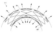
- FIG. 13 in the stent 111 having an open cell structure, when the stent 111 is bent and placed at a bent portion or the like, a part of the strut 117 is likely to jump out radially outward of the stent 111 ( 13), there is a risk of damaging the tissue of a living tubular organ such as a blood vessel.
- the strut 117 of the stent 111 located inside the blood vessel enters the space inside the radial direction of the stent 111 to inhibit blood flow, and there is a risk that thrombosis occurs there (FIG. 13). (Refer to the part surrounded by the one-dot chain line).
- the adhesion to the blood vessel wall BV (indicated by a two-dot chain line in FIGS. 13 and 14) is poor in the bent blood vessel. As a result, there is a gap between the stent and the blood vessel wall BV, and there is a risk that a thrombus may occur. Furthermore, since the adhesion to the blood vessel wall BV is poor, stress concentration occurs on the blood vessel wall BV as shown in FIG. If a stress is locally applied to the blood vessel wall BV by the stress concentration on the blood vessel wall BV by the stent 111, there is a risk of damage to the blood vessel wall BV. Furthermore, at the stress-concentrated site, there is a risk of intimal overgrowth in blood vessels deformed by the stent 111, which reduces wall shear stress that promotes intima neogenesis.
- the axial direction of the stent (axial direction and central axial direction) and the radial direction (direction perpendicular to the axial direction), are important for the realization of a stent with high shape followability.
- the flexibility in the axial direction means rigidity with respect to bending along the axial direction or ease of bending, in order to flexibly bend along the axial direction and adapt to the bending site of the living tubular organ. It is a necessary characteristic.
- the flexibility in the radial direction means rigidity for expansion / contraction in the direction perpendicular to the axial direction or ease of expansion / contraction, and the radius of the stent is adjusted along the shape of the outer wall of the luminal structure of a living tubular organ. This is a characteristic necessary for making the stent adhere to the outer wall of the luminal structure by changing it flexibly.
- the stent has a problem of suppressing shortening (see Patent Document 1).
- a stent mounted in a reduced diameter state on a catheter is expanded (expanded) in a blood vessel during surgery, the entire length of the stent is shortened in the axial direction as compared with crimping (reduced diameter).
- the shortening of the stent in the axial direction is called “shortening”.
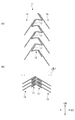
- causes of shortening are as follows. As shown in FIG. 15, when the diameter-reduced stent is deployed, the angle of the top 172 formed by the leg 171 in the cell 117 facing the axial direction LD is increased ( ⁇ 11 ⁇ 12).
- the reference line CL is a line that is parallel to the axial direction LD and passes through the top portion 172.
- the annular body 113 having the cells 117 expands in the circumferential direction, the entire stent 111 is shortened in the axial direction LD.
- the present invention is a flexible stent comprising a plurality of annular bodies having a wavy pattern and arranged in an axial direction, and a plurality of connecting elements extending around the axis and connecting the adjacent annular bodies.
- the wavy pattern is formed by connecting a plurality of substantially V-shaped elements in which two legs are connected at the top, with the tops being alternately reversed in the axial direction.
- the direction in which one end of the connecting element bends and the direction in which the other end of the connecting element bends are opposite, and the end of the connecting element is located in the adjacent annular body.
- a portion other than the top of the V-shaped element extends in a direction different from the direction in which the leg extends, and is connected to the middle of the connecting element when viewed in a radial direction perpendicular to the axial direction.
- the direction in which the part extends is inclined with respect to the axial direction. Cage, one of the two said legs extend along the middle portion of the connecting element, to flexible stent.
- connection element may be connected to the leg portion in each of the V-shaped elements in which the top portion faces the same direction in the axial direction.
- Both of the two leg portions of the V-shaped element may be arranged on the same side with respect to a reference line that is parallel to the axial direction and passes through the top portion.
- the V-shaped element may be rounded in the thickness direction of the V-shaped element along the shape of the virtual outer peripheral curved surface of the flexible stent.
- the direction in which the end portion of the connection element extends and the direction in which the intermediate portion of the connection element extends may be substantially orthogonal to each other.
- the intermediate part of the connecting element and the leg part of the V-shaped element are linear, and the leg part extending along the intermediate part of the connecting element is relative to the intermediate part of the connecting element. It may be parallel.
- connection element may be connected in the vicinity of the connection between the V-shaped elements adjacent in the ring direction of the annular body.
- the two leg portions of the V-shaped element include a long long leg portion and a short short leg portion, and the V-shaped elements adjacent to each other in the ring direction of the annular body are the long leg portion and the short leg portion. And may be connected so that they are adjacent to each other.
- the end of the connecting element may be connected to the long leg of the V-shaped element.
- connection element may be connected to a portion of the V-shaped element on the opposite side of the long leg portion from the top and longer than the short leg portion.
- the angle at which the long leg portion of the V-shaped element is inclined with respect to the axial direction is 50 degrees to 80 degrees, and the angle at which the short leg section of the V-shaped element is inclined is 5 degrees to 30 degrees. There may be.
- a flexible stent that can prevent a strut having a free end from jumping out and suppress shortening during expansion of the stent can be provided.
- FIG. 1 is a perspective view of a flexible stent of one embodiment of the present invention in an unbent state.
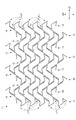
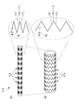
- FIG. FIG. 2 is a development view in which the stent shown in FIG. 1 is virtually developed in a planar shape.
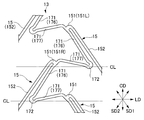
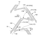
- FIG. 3 is a partially enlarged view of the stent shown in FIG. 2. It is the elements on larger scale of the stent shown in FIG. It is the elements on larger scale of the stent shown in FIG.
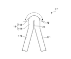
- FIG. 6 is a side view of a V-shaped element of an annulus of a stent.
- FIG. 3 is a partially enlarged view showing the first embodiment of the top of the V-shaped element of the annular body of the stent.
- FIG. 6 is a partially enlarged view showing a second embodiment of the top of the V-shaped element of the annular body of the stent.
- FIG. 6 is a partially enlarged view showing a third embodiment of the top of the V-shaped element of the annular body of the stent.
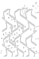
- FIG. 3 is a development view in which a stent in a state in which a tube is laser-processed but an extension process is not performed is virtually expanded in a planar shape. It is a perspective view which shows the state which bent the stent shown in FIG. It is a figure which shows the difference of the length of the axial direction of the stent of this embodiment at the time of expansion
- FIG. 1 is a perspective view of a flexible stent of one embodiment of the present invention in an unbent state.
- FIG. 2 is a development view in which the stent shown in FIG. 1 is virtually developed in a planar shape.
- FIG. 3 is a partially enlarged view of the stent shown in FIG. 4A is a partially enlarged view of the stent shown in FIG. 4B is a partially enlarged view of the stent shown in FIG.
- FIG. 5 is a side view of a V-shaped element of an annulus of a stent.
- the stent 11 has a substantially cylindrical shape.
- the peripheral wall of the stent 11 has a mesh pattern structure in which a plurality of open cells are spread in the circumferential direction.
- the stent 11 is shown in a flat state.
- the peripheral wall of the stent 11 means a portion that separates the inside and the outside of the substantially cylindrical cylinder of the stent 11.
- the cell is also referred to as an opening or a compartment, and refers to a portion surrounded by a wire-like material that forms the mesh pattern of the stent 11.
- the stent 11 is made of stainless steel or a biocompatible material such as tantalum, platinum, gold, cobalt, titanium, or an alloy thereof.
- the stent 11 is preferably formed from a material having superelastic characteristics such as a nickel titanium alloy.
- the stent 11 includes a plurality of annular bodies 13 arranged side by side in the axial direction (longitudinal axis direction, central axial direction) LD, and annular bodies 13, 13 adjacent to the axial direction LD. And a plurality of connection elements 15 for connecting the two.
- the annular body 13 has a wavy pattern formed by connecting a plurality of substantially V-shaped V-shaped elements 17 in the circumferential direction.
- the V-shaped element 17 is formed by connecting two leg portions 171 at a top portion 172.
- a plurality of V-shaped elements 17 are connected in a state where the top portions 172 are alternately reversed in the axial direction LD to form a wavy pattern.
- the ring direction CD of the annular body 13 is not inclined (matches) with respect to the radial direction RD.
- the ring direction CD of the annular body 13 may be inclined with respect to the radial direction RD.
- Both end portions 151 of each connection element 15 connect two annular bodies 13 adjacent to each other in the axial direction LD.
- the end portion 151 of the connecting element 15 is connected to a portion of the adjacent annular body 13 other than the top portion 172 of the V-shaped element 17 in a direction different from the direction in which the leg portion 171 extends.
- All or part of the top 172 of the V-shaped element 17 is a free end. In the present embodiment, all the top portions 172 are free ends. That is, the stent 11 has a so-called open cell structure.
- the leg 171 including the unconnected top 172 forms a strut having a free end.
- the end 151 of the connecting element 15 is connected to the leg 171 in each V-shaped element 17 in which the top 172 faces the same direction in the axial direction LD.
- the plurality of connecting elements 15 are V-shaped elements whose top portions 172 face the same direction in the axial direction LD. 17 is connected to the leg 171 in each. From another viewpoint, the plurality of connecting elements 15 are connected to the V-shaped element 17 every other ring direction CD.
- directions SD1 and SD2 in which the intermediate portion 152 of the connection element 15 extends are inclined with respect to the axial direction LD.
- the two legs 171 and 171 of the V-shaped element 17 are composed of a long long leg 176 and a short short leg 177.
- the V-shaped elements 17 and 17 adjacent to each other in the ring direction CD of the annular body 13 are connected such that the long leg portion 176 and the short leg portion 177 are adjacent to each other.
- the end 151 of the connecting element 15 is connected to the long leg 176 of the V-shaped element 17.
- One of the leg portions 171 (long leg portion 176) extends along the intermediate portion 152 of the connection element 15.
- Both of the two legs 171 (long leg 176, short leg 177) of the V-shaped element 17 are arranged on the same side with respect to a reference line CL that is parallel to the axial direction LD and passes through the top 172. .
- the direction in which the leg portion 171 (long leg portion 176, short leg portion 177) extends is inclined with respect to the axial direction LD.
- the intermediate portion 152 of the connecting element 15 and the leg portion 171 of the V-shaped element 17 are linear.
- the long leg 176 extends along the intermediate part 152 of the connecting element 15.
- the leg 171 (long leg 176) extending along the intermediate part 152 of the connecting element 15 is parallel to the intermediate part 152 of the connecting element 15.
- the directions SD1 and SD2 (see FIG. 4A) in which the long legs 176 extend are inclined with respect to the axial direction LD.
- the direction in which one end 151L of the connecting element 15 is bent is opposite to the direction in which the other end 151R of the connecting element 15 is bent.
- connection element 15 The direction in which the end portion 151 of the connection element 15 extends and the direction in which the intermediate portion 152 of the connection element 15 extends are substantially orthogonal. “Substantially orthogonal” means that the angle formed is 90 ° ⁇ 5 °.
- the angle ⁇ 1 at which the long leg portion 176 of the V-shaped element 17 is inclined with respect to the axial direction LD is 50 to 80 degrees.
- the angle ⁇ 2 at which the short leg portion 177 of the V-shaped element 17 is inclined is 5 to 30 degrees.
- the end 151 of the connecting element 15 is connected in the vicinity of the connecting part 173 between the V-shaped elements 17 and 17 adjacent to each other in the ring direction of the annular body 13.
- the end portion 151 of the connecting element 15 is connected to a portion 178 of the long leg portion 176 of the V-shaped element 17 that is opposite to the top portion 172 and longer than the short leg portion 177.
- a curved arrow in a two-dot chain line in FIG. 4B indicates a position corresponding to the length of the short leg 177 in the long leg 176.
- the V-shaped element 17 is rounded in the thickness direction of the V-shaped element 17 along the shape of the virtual outer peripheral curved surface of the flexible stent 11.
- the virtual outer peripheral curved surface has a substantially cylindrical shape.
- the V-shaped element 17 extends toward the top 172 while being inclined with respect to the axial direction LD. Accordingly, the V-shaped element 17 has a three-dimensional curved surface in the thickness direction of the V-shaped element 17.
- Such a rounded V-shaped element 17 having a three-dimensional curved surface can be easily obtained by laser processing a substantially cylindrical tube.
- the V-shaped element 17 is shown as being rounded two-dimensionally, but is actually rounded as a three-dimensional curved surface. Further, even if the sheet-like material is subjected to laser processing or the like to form a net shape and then formed into a substantially cylindrical shape, the V-shaped element 17 in that case generally has a thickness of the V-shaped element 17. Do not round the 3D curved surface. Generally, the width of the leg portion 171 of the V-shaped element 17 is very narrow, and the rigidity in the width direction of the leg portion 171 of the V-shaped element 17 is very high.
- FIG. 6 is a partially enlarged view showing the first embodiment of the top of the V-shaped element of the annular body of the stent.
- FIG. 7 is a partially enlarged view showing a second embodiment of the top of the V-shaped element of the stent annular body.
- FIG. 8 is a partially enlarged view showing a third embodiment of the top of the V-shaped element of the annular body of the stent.
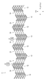
- FIG. 9 is a development view in which the stent in a state where the tube is laser-processed but the stretching process is not performed is virtually expanded in a planar shape.
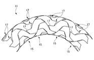
- FIG. 10 is a perspective view showing a state where the stent shown in FIG. 1 is bent.
- FIG. 10 is a perspective view showing a state where the stent shown in FIG. 1 is bent.
- FIG. 11 is a diagram showing a difference in length in the axial direction of the stent of the present embodiment between the expanded state and the reduced diameter in the expanded state.
- FIG. 12 is a diagram showing a difference in length in the axial direction of a conventional stent between an expanded state and a contracted diameter in an expanded state.
- FIG. 13 is a schematic diagram showing a strut state in a state where a conventional stent is bent.
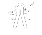
- a ridge 19 is formed at the top 172 of the V-shaped element 17.
- the knob-like portion 19 includes an extended portion 191 that is inclined with respect to the axial direction LD and extends linearly, and a substantially semicircular portion (tip portion) 192 formed at the tip thereof.
- the extension 191 has a width that is greater than the width of the connecting element 15.
- a slit 21 extending from the inner peripheral edge along the direction in which the extended portion 191 extends is formed in the top 172 of the V-shaped element 17. For this reason, the two leg portions 171 are connected to the region where the slit 21 is not provided in the extended portion 191 and the substantially semicircular portion 192 of the knob-shaped portion 19.
- tip part 192 is a substantially semicircle substantially semicircle part, it does not need to be a substantially semicircle (not shown).
- the knob portion 19 has an effect of reducing metal fatigue.
- the slit 21 has an effect of improving the diameter reduction property of the stent 11.
- the deformation of the V-shaped element 17 is performed around the root valley side portion (inner peripheral edge portion) of the V-shaped element 17, and it is substantially the ridge-side portion of the top 172 of the V-shaped element 17 that contributes to the deformation ( The range indicated by the double-sided arrows in the upper part of FIGS. Therefore, in the stent 11, as shown in FIGS. 6 to 8, the ridge portion 19 including the extended portion 191 and the substantially semicircular portion 192 and having a width larger than the width of the connecting element 15 is formed on the top portion.
- the top portion 172 is extended by being formed at 172.
- an extended portion 191 extending in the axial direction LD is provided between the leg portion 171 of the V-shaped element 17 and the substantially semicircular portion 192 that forms the top 172 thereof, and the V-shaped element serving as a deformation base point
- the top part 172 is offset from the root valley side part (inner peripheral edge part) of 17 toward the outside. Thereby, the outer peripheral part of the top part 172 is lengthened.
- the extended portion 191 prevents the diameter-decreasing portion 19 from coming into contact with each other in the circumferential direction when the diameter is reduced. It is desirable to form by the straight part extended in this.
- the extension portion 191 has a length equal to or shorter than the length of the slit 21, as shown in FIG. Is longer than the length of the slit 21, and the extended portion 191 preferably extends beyond the tip of the slit 21.
- the opposing side edges of the slit 21 are linear shapes extending substantially in parallel.
- the opposing side edge of the slit 21 does not need to extend substantially in parallel (for example, it may extend slightly toward the leg part 171). Further, the opposing side edges of the slit 21 may not be linear (not shown).
- the stent 11 is inserted into the catheter in a state of being reduced in diameter, is pushed by an pusher such as a pusher, moves through the catheter, and is deployed at a lesion site. At this time, the force in the axial direction LD applied by the extruder is transmitted to the entire stent 11 while interacting between the annular body 13 and the connecting element 15 of the stent 11.
- the stent 11 having the above-described structure is manufactured by laser processing, for example, a biocompatible material, particularly preferably a tube formed of a superelastic alloy.
- a biocompatible material particularly preferably a tube formed of a superelastic alloy.
- the tube of about 2 to 3 mm is once laser processed to reduce the cost.
- FIG. 9 shows a state in which the stent 11 at this point, that is, the stent 11 in which the tube is laser-processed but not subjected to the extending process is virtually expanded in a planar shape.
- both of the two leg portions 171 (long leg portion 176 and short leg portion 177) of the V-shaped element 17 are parallel to each other and on the same side with respect to the axial direction LD (reference line CL). Has been placed.
- FIG. 2 shows a state in which the stent 11 at this point is virtually expanded in a planar shape. It is preferable that the stent 11 is manufactured by applying a shape memory process to the tube. The production of the stent 11 is not limited to laser machining, and can be produced by other methods such as cutting.
- a catheter is inserted into the patient's blood vessel and allowed to reach the lesion site.
- the stent 11 is reduced in diameter (crimped) and placed in the catheter.
- the stent having a reduced diameter is pushed along the lumen of the catheter using an extruder such as a pusher, and the stent 11 is pushed out from the distal end of the catheter at the lesion site to be expanded (expanded). Then, the stent 11 can be placed.
- the stent 11 of the present embodiment has the above-described configurations.
- the wavy pattern is formed by connecting a plurality of substantially V-shaped elements 17 in which two leg portions 171 are connected at the top portion 172 with the top portions 172 alternately directed in the axial direction LD, Is formed.
- the direction in which the intermediate portion 152 of the connecting element 15 extends is inclined with respect to the axial direction LD.
- One of the two legs 171 extends along the intermediate part 152 of the connecting element 15.
- connection element 15 is connected to the leg portion 171 of each V-shaped element 17 in which the top portion 172 faces the same direction in the axial direction LD.
- Both the two legs 171 of the V-shaped element 17 are disposed on the same side with respect to the reference line CL.
- the V-shaped element 17 is rounded in the thickness direction of the V-shaped element 17 along the shape of the virtual outer peripheral curved surface of the flexible stent 11.
- the intermediate part 152 of the connecting element 15 and the leg part 171 of the V-shaped element 17 are linear. Legs 171 extending along the intermediate part 152 of the connecting element 15 are parallel to the intermediate part 152 of the connecting element 15.
- the two legs 171 of the V-shaped element 17 are composed of a long long leg 176 and a short short leg 177.
- the V-shaped elements 17 adjacent to each other in the ring direction CD of the annular body 13 are connected such that the long leg portion 176 and the short leg portion 177 are adjacent to each other.
- the end 151 of the connecting element 15 is connected to the long leg 176 of the V-shaped element 17.
- the end portion 151 of the connecting element 15 is connected to a portion 178 of the long leg portion 176 of the V-shaped element 17 that is opposite to the top portion 172 and longer than the short leg portion 177.
- the stent 11 of this embodiment is bent and placed in a bent portion of a blood vessel or the like, a strut having a free end is formed.
- the character element 17 is unlikely to jump out radially outward of the stent 111 in a flared shape.
- the stent 11 of the present embodiment is less likely to damage a tissue of a living tubular organ such as a blood vessel, and has a low risk of thrombosis on the radially inner side of the stent. Adhesion is excellent, and stress concentration on the blood vessel wall is reduced.
- the stent 11 (see FIG. 11B) mounted on the catheter in a reduced diameter state is deployed in the blood vessel during the operation.
- the entire length of the stent 11 is shortened in the axial direction LD as compared to the crimping (reducing diameter).
- the shortened length in this case is indicated by ⁇ L1.
- FIG. 12 As a comparison object, a conventional stent 111 is shown in FIG. As shown in FIG. 12, when a stent 111 (see FIG. 12B) mounted in a reduced diameter state on a catheter is expanded (expanded) in a blood vessel during surgery (see FIG. 12A), The entire length of the stent 111 is shortened in the axial direction LD as compared with the crimping (reduction). The shortened length in this case is indicated by ⁇ L2.
- Reference numeral 115 denotes a connection element. As is apparent from a comparison between ⁇ L1 shown in FIG. 11 and ⁇ L2 shown in FIG. 12, the stent 11 of this embodiment has a high effect of suppressing shortening.
- the V-shaped element 17 may not be rounded in the thickness direction.
- the intermediate portion 152 of the connecting element 15 and the leg portion 171 of the V-shaped element 17 may not be linear.
- the legs 171 extending along the intermediate part 152 of the connecting element 15 may not be parallel to the intermediate part 152 of the connecting element 15.
- the lengths of the two legs 171 of the V-shaped element 17 may be the same.
Landscapes
- Health & Medical Sciences (AREA)
- Engineering & Computer Science (AREA)
- Biomedical Technology (AREA)
- Heart & Thoracic Surgery (AREA)
- Life Sciences & Earth Sciences (AREA)
- Cardiology (AREA)
- Oral & Maxillofacial Surgery (AREA)
- Transplantation (AREA)
- Physics & Mathematics (AREA)
- Vascular Medicine (AREA)
- Optics & Photonics (AREA)
- Animal Behavior & Ethology (AREA)
- General Health & Medical Sciences (AREA)
- Public Health (AREA)
- Veterinary Medicine (AREA)
- Media Introduction/Drainage Providing Device (AREA)
- Prostheses (AREA)
Priority Applications (6)
| Application Number | Priority Date | Filing Date | Title |
|---|---|---|---|
| EP14887248.4A EP3123983B1 (en) | 2014-03-25 | 2014-03-26 | Flexible stent |
| US15/128,796 US10420660B2 (en) | 2014-03-25 | 2014-03-26 | Flexible stent |
| AU2014388753A AU2014388753B2 (en) | 2014-03-25 | 2014-03-26 | Flexible stent |
| ES14887248T ES2874058T3 (es) | 2014-03-25 | 2014-03-26 | Stent flexible |
| CN201480012855.4A CN105142580B (zh) | 2014-03-25 | 2014-03-26 | 柔性支架 |
| CA2956511A CA2956511C (en) | 2014-03-25 | 2014-03-26 | Flexible stent |
Applications Claiming Priority (2)
| Application Number | Priority Date | Filing Date | Title |
|---|---|---|---|
| JP2014-061130 | 2014-03-25 | ||
| JP2014061130A JP6081948B2 (ja) | 2014-03-25 | 2014-03-25 | 柔軟性ステント |
Publications (1)
| Publication Number | Publication Date |
|---|---|
| WO2015145596A1 true WO2015145596A1 (ja) | 2015-10-01 |
Family
ID=54194194
Family Applications (1)
| Application Number | Title | Priority Date | Filing Date |
|---|---|---|---|
| PCT/JP2014/058415 Ceased WO2015145596A1 (ja) | 2014-03-25 | 2014-03-26 | 柔軟性ステント |
Country Status (8)
| Country | Link |
|---|---|
| US (1) | US10420660B2 (enExample) |
| EP (1) | EP3123983B1 (enExample) |
| JP (1) | JP6081948B2 (enExample) |
| CN (1) | CN105142580B (enExample) |
| AU (1) | AU2014388753B2 (enExample) |
| CA (1) | CA2956511C (enExample) |
| ES (1) | ES2874058T3 (enExample) |
| WO (1) | WO2015145596A1 (enExample) |
Cited By (2)
| Publication number | Priority date | Publication date | Assignee | Title |
|---|---|---|---|---|
| WO2022034905A1 (ja) * | 2020-08-12 | 2022-02-17 | 康宏 正林 | ステント |
| RU2784857C1 (ru) * | 2020-08-12 | 2022-11-30 | Ясухиро СЁБАЯСИ | Стент |
Families Citing this family (4)
| Publication number | Priority date | Publication date | Assignee | Title |
|---|---|---|---|---|
| US10500078B2 (en) | 2018-03-09 | 2019-12-10 | Vesper Medical, Inc. | Implantable stent |
| US11986408B2 (en) | 2020-07-24 | 2024-05-21 | Medtronic Vascular, Inc. | Stent with mid-crowns |
| US11998464B2 (en) | 2020-07-24 | 2024-06-04 | Medtronic Vascular, Inc. | Stent with angled struts and crowns |
| WO2024080365A1 (ja) * | 2022-10-14 | 2024-04-18 | 株式会社Bolt Medical | 遠位スタビライザ |
Citations (5)
| Publication number | Priority date | Publication date | Assignee | Title |
|---|---|---|---|---|
| JP2001501488A (ja) * | 1995-10-16 | 2001-02-06 | グロバーマン,オーレン | 医療用ステント及びその製造装置及び製造方法 |
| US6331189B1 (en) * | 1999-10-18 | 2001-12-18 | Medtronic, Inc. | Flexible medical stent |
| JP2003250906A (ja) * | 2002-03-05 | 2003-09-09 | Nec Tokin Corp | ステント |
| JP2004508880A (ja) * | 2000-09-23 | 2004-03-25 | シメッド ライフ システムズ インコーポレイテッド | 階段状の拡張支柱対と、拡張支柱から反対側に延在した2段の階段状の斜めの結合支柱とを備えてなる血管内ステント |
| JP2004202238A (ja) * | 2002-12-20 | 2004-07-22 | Biotronik Gmbh & Co Kg | ステント |
Family Cites Families (37)
| Publication number | Priority date | Publication date | Assignee | Title |
|---|---|---|---|---|
| US6287336B1 (en) * | 1995-10-16 | 2001-09-11 | Medtronic, Inc. | Variable flexibility stent |
| US6334871B1 (en) * | 1996-03-13 | 2002-01-01 | Medtronic, Inc. | Radiopaque stent markers |
| US20020042647A1 (en) * | 2000-09-22 | 2002-04-11 | Jang G. David | Intravascular stent apparatus |
| US20040106985A1 (en) | 1996-04-26 | 2004-06-03 | Jang G. David | Intravascular stent |
| US6033433A (en) * | 1997-04-25 | 2000-03-07 | Scimed Life Systems, Inc. | Stent configurations including spirals |
| US6451049B2 (en) * | 1998-04-29 | 2002-09-17 | Sorin Biomedica Cardio, S.P.A. | Stents for angioplasty |
| IT1292295B1 (it) * | 1997-04-29 | 1999-01-29 | Sorin Biomedica Cardio Spa | Stent per angioplastica |
| US6261319B1 (en) | 1998-07-08 | 2001-07-17 | Scimed Life Systems, Inc. | Stent |
| US6042597A (en) * | 1998-10-23 | 2000-03-28 | Scimed Life Systems, Inc. | Helical stent design |
| US6730116B1 (en) * | 1999-04-16 | 2004-05-04 | Medtronic, Inc. | Medical device for intraluminal endovascular stenting |
| DE19951611A1 (de) * | 1999-10-26 | 2001-05-10 | Biotronik Mess & Therapieg | Stent mit geschlossener Struktur |
| US7766956B2 (en) * | 2000-09-22 | 2010-08-03 | Boston Scientific Scimed, Inc. | Intravascular stent and assembly |
| US20020045935A1 (en) * | 2000-09-23 | 2002-04-18 | Jang G. David | Intravascular stent apparatus |
| WO2002026164A2 (en) * | 2000-09-25 | 2002-04-04 | Jang G David | Intravascular stent apparatus |
| DE10050970A1 (de) * | 2000-10-10 | 2002-04-11 | Biotronik Mess & Therapieg | Stent |
| US6485508B1 (en) * | 2000-10-13 | 2002-11-26 | Mcguinness Colm P. | Low profile stent |
| PT2311411E (pt) * | 2000-12-11 | 2015-11-17 | Orbusneich Medical Inc | Endoprótese com elementos helicoidais |
| CN1255084C (zh) | 2001-02-09 | 2006-05-10 | 奥勃斯医学技术股份有限公司 | 具有螺旋状元件的可弯皱管腔内用内支架 |
| US6942689B2 (en) * | 2001-03-01 | 2005-09-13 | Cordis Corporation | Flexible stent |
| US20050080479A1 (en) * | 2003-09-29 | 2005-04-14 | Feng James Q. | Expandable endovascular stent |
| US7651524B2 (en) * | 2005-03-30 | 2010-01-26 | Terumo Kabushiki Kaisha | Flexible stent |
| US7404823B2 (en) * | 2005-10-31 | 2008-07-29 | Boston Scientific Scimed, Inc. | Stent configurations |
| US20080077231A1 (en) | 2006-07-06 | 2008-03-27 | Prescient Medical, Inc. | Expandable vascular endoluminal prostheses |
| US8974514B2 (en) | 2007-03-13 | 2015-03-10 | Abbott Cardiovascular Systems Inc. | Intravascular stent with integrated link and ring strut |
| FR2913680B1 (fr) * | 2007-03-14 | 2009-07-03 | Commissariat Energie Atomique | Synthese d'un compose limpo4 et utilisation comme materiau d'electrode dans un accumulateur au lithium |
| US20080319528A1 (en) * | 2007-06-25 | 2008-12-25 | Abbott Laboratories | Modular endoprosthesis with flexible interconnectors between modules |
| US9144508B2 (en) * | 2007-07-19 | 2015-09-29 | Back Bay Medical Inc. | Radially expandable stent |
| JP5401148B2 (ja) | 2009-03-31 | 2014-01-29 | テルモ株式会社 | 生体内留置用ステントおよび生体器官拡張器具 |
| WO2010124286A1 (en) * | 2009-04-24 | 2010-10-28 | Flexible Stenting Solutions, Inc. | Flexible devices |
| EP2266508A1 (de) * | 2009-06-25 | 2010-12-29 | Biotronik VI Patent AG | Stent mit verbessertem Stentdesign |
| KR20160102095A (ko) * | 2010-08-02 | 2016-08-26 | 코디스 코포레이션 | 돌출 힌지들을 갖는 가요성 스텐트 |
| AU2011285812B2 (en) * | 2010-08-02 | 2015-04-30 | Cardinal Health 529, Llc | Flexible helical stent having different helical regions |
| KR101644410B1 (ko) * | 2010-08-02 | 2016-08-01 | 코디스 코포레이션 | 중간 구조적 피쳐를 갖는 가요성 나선형 스텐트 |
| US20130178928A1 (en) * | 2010-09-13 | 2013-07-11 | Rajnikant Gandalal Vyas | Stents with low strut thickness and variable strut geometry |
| DE102011115902B4 (de) * | 2010-12-22 | 2021-07-01 | Bentley Innomed Gmbh | Stent-Graft und dessen Verwendung |
| EP2710984B1 (en) * | 2012-09-19 | 2015-08-26 | Biotronik AG | Implant and system formed of a balloon catheter and implant |
| US10758384B2 (en) * | 2016-07-13 | 2020-09-01 | Cook Medical Technologies Llc | Stent having reduced foreshortening |
-
2014
- 2014-03-25 JP JP2014061130A patent/JP6081948B2/ja not_active Expired - Fee Related
- 2014-03-26 ES ES14887248T patent/ES2874058T3/es active Active
- 2014-03-26 CA CA2956511A patent/CA2956511C/en active Active
- 2014-03-26 AU AU2014388753A patent/AU2014388753B2/en not_active Ceased
- 2014-03-26 US US15/128,796 patent/US10420660B2/en active Active
- 2014-03-26 WO PCT/JP2014/058415 patent/WO2015145596A1/ja not_active Ceased
- 2014-03-26 CN CN201480012855.4A patent/CN105142580B/zh active Active
- 2014-03-26 EP EP14887248.4A patent/EP3123983B1/en active Active
Patent Citations (5)
| Publication number | Priority date | Publication date | Assignee | Title |
|---|---|---|---|---|
| JP2001501488A (ja) * | 1995-10-16 | 2001-02-06 | グロバーマン,オーレン | 医療用ステント及びその製造装置及び製造方法 |
| US6331189B1 (en) * | 1999-10-18 | 2001-12-18 | Medtronic, Inc. | Flexible medical stent |
| JP2004508880A (ja) * | 2000-09-23 | 2004-03-25 | シメッド ライフ システムズ インコーポレイテッド | 階段状の拡張支柱対と、拡張支柱から反対側に延在した2段の階段状の斜めの結合支柱とを備えてなる血管内ステント |
| JP2003250906A (ja) * | 2002-03-05 | 2003-09-09 | Nec Tokin Corp | ステント |
| JP2004202238A (ja) * | 2002-12-20 | 2004-07-22 | Biotronik Gmbh & Co Kg | ステント |
Cited By (9)
| Publication number | Priority date | Publication date | Assignee | Title |
|---|---|---|---|---|
| WO2022034905A1 (ja) * | 2020-08-12 | 2022-02-17 | 康宏 正林 | ステント |
| JP7029578B1 (ja) * | 2020-08-12 | 2022-03-03 | 康宏 正林 | ステント |
| KR20220039830A (ko) * | 2020-08-12 | 2022-03-29 | 야스히로 쇼바야시 | 스텐트 |
| CN114364351A (zh) * | 2020-08-12 | 2022-04-15 | 正林康宏 | 支架 |
| AU2021326319A1 (en) * | 2020-08-12 | 2022-04-21 | Yasuhiro Shobayashi | Stent |
| AU2021326319B2 (en) * | 2020-08-12 | 2022-05-12 | Yasuhiro Shobayashi | Stent |
| RU2784857C1 (ru) * | 2020-08-12 | 2022-11-30 | Ясухиро СЁБАЯСИ | Стент |
| US11590009B2 (en) | 2020-08-12 | 2023-02-28 | Yasuhiro Shobayashi | Stent |
| KR102558760B1 (ko) | 2020-08-12 | 2023-07-24 | 야스히로 쇼바야시 | 스텐트 |
Also Published As
| Publication number | Publication date |
|---|---|
| EP3123983A1 (en) | 2017-02-01 |
| US20170100268A1 (en) | 2017-04-13 |
| EP3123983A4 (en) | 2017-08-23 |
| CA2956511C (en) | 2018-11-06 |
| AU2014388753A1 (en) | 2016-11-10 |
| JP2015181746A (ja) | 2015-10-22 |
| CN105142580A (zh) | 2015-12-09 |
| CN105142580B (zh) | 2017-03-15 |
| EP3123983B1 (en) | 2021-05-12 |
| US10420660B2 (en) | 2019-09-24 |
| ES2874058T3 (es) | 2021-11-04 |
| JP6081948B2 (ja) | 2017-02-15 |
| AU2014388753B2 (en) | 2017-07-13 |
| CA2956511A1 (en) | 2015-10-01 |
Similar Documents
| Publication | Publication Date | Title |
|---|---|---|
| JP6095493B2 (ja) | 高い疲労抵抗を有する移植片、移植片送達システム、および使用法 | |
| JP6479493B2 (ja) | 高柔軟性ステント | |
| JP4844394B2 (ja) | ステント | |
| JP7797603B2 (ja) | 減少した短縮および反跳を有するステントデバイスおよびその製造方法 | |
| US11364135B2 (en) | Stent | |
| JP6081948B2 (ja) | 柔軟性ステント | |
| US9259335B2 (en) | Stent | |
| JP2008237880A (ja) | 周囲において変化する軸方向の可撓性を有する管腔内医療装置 | |
| JP2015008931A (ja) | 高柔軟性ステント | |
| CN109966017B (zh) | 覆膜支架 | |
| CN112807141A (zh) | 支架及其检查方法 | |
| JP6688125B2 (ja) | 高柔軟性ステント | |
| JP4835113B2 (ja) | ステント | |
| JP2011160915A (ja) | ステント及びその製造方法 | |
| JP5550028B1 (ja) | 高柔軟性ステント | |
| JP2014226353A (ja) | ステント | |
| JP2004305450A (ja) | 血管追従性の優れた均一に拡張する柔軟なステント | |
| JP2005205022A (ja) | 血管追従性および拡張性のよい、血管に優しい柔軟なステント | |
| JP2004344204A (ja) | 均一に拡張する柔軟なステント |
Legal Events
| Date | Code | Title | Description |
|---|---|---|---|
| WWE | Wipo information: entry into national phase |
Ref document number: 201480012855.4 Country of ref document: CN |
|
| 121 | Ep: the epo has been informed by wipo that ep was designated in this application |
Ref document number: 14887248 Country of ref document: EP Kind code of ref document: A1 |
|
| NENP | Non-entry into the national phase |
Ref country code: DE |
|
| REEP | Request for entry into the european phase |
Ref document number: 2014887248 Country of ref document: EP |
|
| WWE | Wipo information: entry into national phase |
Ref document number: 2014887248 Country of ref document: EP |
|
| ENP | Entry into the national phase |
Ref document number: 2014388753 Country of ref document: AU Date of ref document: 20140326 Kind code of ref document: A |
|
| WWE | Wipo information: entry into national phase |
Ref document number: 15128796 Country of ref document: US |
|
| ENP | Entry into the national phase |
Ref document number: 2956511 Country of ref document: CA |