WO2015145545A1 - 補強フィルム接着装置 - Google Patents
補強フィルム接着装置 Download PDFInfo
- Publication number
- WO2015145545A1 WO2015145545A1 PCT/JP2014/058085 JP2014058085W WO2015145545A1 WO 2015145545 A1 WO2015145545 A1 WO 2015145545A1 JP 2014058085 W JP2014058085 W JP 2014058085W WO 2015145545 A1 WO2015145545 A1 WO 2015145545A1
- Authority
- WO
- WIPO (PCT)
- Prior art keywords
- fastener chain
- reinforcing film
- film
- ultrasonic horn
- anvil
- Prior art date
- Legal status (The legal status is an assumption and is not a legal conclusion. Google has not performed a legal analysis and makes no representation as to the accuracy of the status listed.)
- Ceased
Links
Images





Classifications
-
- A—HUMAN NECESSITIES
- A44—HABERDASHERY; JEWELLERY
- A44B—BUTTONS, PINS, BUCKLES, SLIDE FASTENERS, OR THE LIKE
- A44B19/00—Slide fasteners
- A44B19/42—Making by processes not fully provided for in one other class, e.g. B21D53/50, B21F45/18, B22D17/16, B29D5/00
- A44B19/60—Applying end stops upon stringer tapes
Definitions
- the present invention relates to a reinforcing film bonding apparatus, for example, a reinforcing film bonding apparatus that attaches a synthetic resin reinforcing film to a space portion of a fastener chain of a slide fastener.
- Patent Documents As a conventional reinforcing film bonding apparatus, an apparatus that bonds a reinforcing film piece made of a thermoplastic synthetic resin to the upper and lower surfaces of a fastener chain in a space portion of a fastener chain that is intermittently conveyed is known (for example, Patent Documents). 1).
- the reinforcement film bonding apparatus of the said patent document 1 is equipped with the ultrasonic horn provided in the upper surface side of a fastener chain so that a vertical movement is possible, and the anvil provided in a lower surface side of a fastener chain so that a vertical movement is possible.
- the ultrasonic horn and the anvil there are provided a molding part for forming a core string of the fastener chain and a fusing mold part for punching a window hole.
- the present invention has been made in view of the above-described circumstances, and an object thereof is to provide a reinforcing film bonding apparatus capable of bonding a reinforcing film up to the inner surface of a core string of a fastener chain.
- a chain conveying device for intermittently conveying a fastener chain for intermittently conveying a fastener chain, a film supply device for supplying a synthetic resin reinforcing film to the upper and lower surfaces of the fastener chain, and an ultrasonic horn provided on one surface side of the fastener chain so as to be movable up and down.
- an anvil provided on the other surface side of the fastener chain so as to be movable up and down, and an adhesive device for bonding the reinforcing film to the upper and lower surfaces of the fastener chain, respectively, and an ultrasonic horn
- a convex portion is formed on the pressing surface of the fastener chain so as to enter between the pair of fastener tapes of the fastener chain when the ultrasonic horn is moved, and the pair of core strings of the fastener chain is accommodated on the pressing surface of the anvil when the anvil is moved.
- a reinforcing film bonding apparatus characterized in that a pair of recesses are formed.
- the adhesive film cutting apparatus cuts the reinforcing film with an ultrasonic horn and an anvil, and bonds the cut reinforcing film to the upper and lower surfaces of the fastener chain, respectively. .
- a gripper that grips the reinforcing film from the film supply device and draws it out to the fastener chain side, and a cutting device that has a cutter that cuts the reinforcing film drawn out by the gripper, and includes a cutter and a cutting portion of the film supply device.
- the reinforcing film bonding apparatus according to (1) wherein the reinforcing film is cut between the front end surface and the cut reinforcing film is bonded to the upper and lower surfaces of the fastener chain.
- a convex portion that enters between the pair of fastener tapes of the fastener chain is formed on the pressing surface of the ultrasonic horn when the ultrasonic horn is moved. Since the pair of recesses for accommodating the pair of core strings of the fastener chain is formed during the movement, the reinforcing film can be bonded to the inner side surface of the core string of the fastener chain.
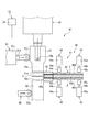
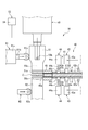
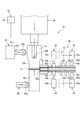
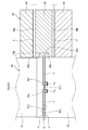
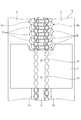
- FIG. 1 is a schematic side view illustrating a first embodiment of a reinforcing film bonding apparatus according to the present invention. It is the partially cutaway side view which looked at the reinforcement film bonding apparatus shown in FIG. 1 from the downstream. It is an enlarged view of the periphery of the fastener chain of FIG. It is an enlarged view of the cutting part of the film supply apparatus shown in FIG. It is a side view corresponding to Drawing 2 explaining the state where the upper and lower reinforcement films are conveyed by the film supply device to the upper and lower surfaces of the fastener chain between the ultrasonic horn and the anvil, respectively.
- FIG. 3 is a side view corresponding to FIG.
- the upper side is the upper side with respect to the paper surface of FIG. 1
- the lower side is the lower side with respect to the paper surface of FIG. 1
- the left side is with respect to the paper surface of FIG.
- the near side and the right side are the back side with respect to the paper surface of FIG. 1
- the upstream side is the left side with respect to the paper surface of FIG. 1
- the downstream side is the right side with respect to the paper surface of FIG.
- the left-right direction of a reinforcement film bonding apparatus is also called the width direction.
- the reinforcing film bonding apparatus 10 includes a chain conveying device 20 that intermittently conveys the fastener chain C, and chain guide plates 31 and 32 that guide the conveyed fastener chain C.
- the upper and lower surfaces of the fastener chain C and the upper and lower surfaces of the fastener chain C are cut into the upper and lower reinforcing films F and the film supply device 40 for supplying the synthetic resin reinforcing films F to the upper and lower surfaces.
- a welding device (adhesive device) 50 for welding each, and the cut reinforcing film F is welded to the fastener tape T in the space S portion of the fastener chain C.
- the fastener chain C includes a pair of left and right fastener tapes T and a pair of left and right fastener elements attached along the core string Ta at the tape side edge portions of the pair of left and right fastener tapes T facing each other.
- the fastener element row EL has a plurality of fastener elements E.
- the fastener element row EL is a coiled fastener element row.
- the fastener chain C is formed with a space S at a predetermined interval in which the fastener element E is not attached or the fastener element E is removed and the side edges of the tape face each other.
- the chain transport device 20 includes a feed roll device 21 that transports the fastener chain C, and a space detection device 22 that detects a space S of the fastener chain C.
- the feed roll device 21 includes a feed roller 21a disposed below the fastener chain C and a press roller 21b disposed above the fastener chain C. Moreover, in the feed roll apparatus 21, the feed length of the fastener chain C is measured in the feed roller 21a.
- the space detection device 22 includes a swing lever 22a having a sensing roller 22b at the tip. In the space detection device 22, when the sensing roller 22b enters the space S of the fastener chain C to be conveyed, the swing lever 22a swings downward and the space S is detected.
- the space S of the fastener chain C conveyed by the feed roll device 21 is detected by the space detecting device 22, the space S of the fastener chain C is a predetermined position of the welding device 50.
- the feed chain device 21 stops the conveyance of the fastener chain C so as to stop. And the fastener chain C is intermittently conveyed by repeating the said operation
- the film supply device 40 is inserted through a film transport unit 41 that transports the upper and lower reinforcing films F and an upper and lower reinforcing film F that is transported from the film transport unit 41. And a cutting portion 45 that cuts the upper and lower reinforcing films F between the ultrasonic horn 51 and the anvil 52.
- the film supply device 40 is provided so as to extend from the welding device 50 to the right side in the width direction.
- the welding device 50 includes an ultrasonic horn 51 provided on the upper surface side of the fastener chain C so as to be movable up and down, and an anvil 52 provided on the lower surface side of the fastener chain C so as to be movable up and down. .
- the ultrasonic horn 51 is formed at the lower end surface, which is a pressing surface 51 a that presses the reinforcing film F against the upper surface of the fastener chain C, and the left and right edges of the pressing surface 51 a. And a cutting blade 51b.
- the right cutting blade 51b is used for cutting
- the left cutting blade 51b is used with its right and left reversed when the right cutting blade 51b is worn.
- a convex portion 51c that enters between the left and right fastener tapes T of the fastener chain C when the ultrasonic horn 51 is moved downward (when the film is welded, see FIG. 7) is pressed on the pressing surface 51a of the ultrasonic horn 51. It is formed along the conveyance direction of the fastener chain C at the center in the width direction of the surface 51a.
- the anvil 52 is formed at the upper end surface of the pressing surface 52 a that presses the reinforcing film F against the lower surface of the fastener chain C, and the left and right edges of the pressing surface 52 a, and cuts the reinforcing film F.
- Cutting blade 52b is used for cutting, and the left cutting blade 52b is used with its right and left reversed when the right cutting blade 52b is worn.
- the pressing surface 52a of the anvil 52 has a pair of recesses 52c for receiving the left and right core strings Ta of the fastener chain C when the anvil 52 is moved upward (when the film is welded, see FIG. 7). It is formed along the conveyance direction of the fastener chain C at symmetrical positions with the width direction center therebetween.
- the reinforcing film bonding apparatus 10 includes a first preloading device 61 and a second preloading device 62 that urge the ultrasonic horn 51 and the anvil 52 of the welding device 50 toward the film supply device 40, respectively. Prepare. For this reason, the cutting blades 51b and 52b of the ultrasonic horn 51 and the anvil 52 are pressed against the distal end surface 45a of the cutting portion 45 of the film supply device 40 by the urging force of the first preloading device 61 and the second preloading device 62. The reinforcing film F can be cut efficiently.
- the first preload device 61 includes a cylinder 61a and a pressing roller 61c attached to the tip of the rod 61b of the cylinder 61a.
- the second preloading device 62 includes a pressing roller 62a that is constantly urged toward the anvil 52 side by a spring (not shown). Then, the first preload device 61 is driven so that the rod 61 b is contracted after the film is cut by the ultrasonic horn 51 and the pressing roller 61 c is separated from the ultrasonic horn 51. For this reason, since the ultrasonic horn 51 and the pressing roller 61c become non-contact, the vibration of the ultrasonic horn 51 performed after film cutting is not inhibited.
- the ultrasonic horn 51 is provided with an adsorption device 53 for adsorbing the cut reinforcing film F as shown in FIG. 1 and FIG.
- the suction device 53 communicates with two vertical holes 53 a that open in the pressing surface 51 a of the ultrasonic horn 51 and the upper ends of the two vertical holes 53 a, and one horizontal hole 53 b that opens in the side surface of the ultrasonic horn 51.
- a suction device 54 connected to the lateral hole 53b. Examples of the suction device 54 include a vacuum pump and a suction pump.
- the two vertical holes 53a of the suction device 53 are formed in parallel along the conveying direction of the fastener chain C at the center in the width direction of the ultrasonic horn 51, as shown in FIGS. Accordingly, the openings of the two vertical holes 53 a are arranged on the convex portion 51 c of the pressing surface 51 a of the ultrasonic horn 51. For this reason, the adsorption trace Ft by adsorption
- the suction device 54 sucks air from the two vertical holes 53a when the film is cut, so that the cut upper reinforcing film F is applied to the pressing surface 51a of the ultrasonic horn 51. Adsorbed. For this reason, the position shift of the reinforcing film F at the time of cutting the reinforcing film F with the ultrasonic horn 51 is prevented. Further, after the film is welded, the dust from the reinforcing film F that has melted and entered the two vertical holes 53a is discharged to the outside by spraying air from the two vertical holes 53a. Thereby, clogging of the two vertical holes 53a can be prevented.
- the film transport unit 41 of the film supply device 40 includes a film guide 42 that guides the upper and lower reinforcing films F, and an upper and lower first pressing device that transports the upper and lower reinforcing films F to the welding device 50 side. 43 and upper and lower second pressing devices 44 that fix the positions of the conveyed upper and lower reinforcing films F.
- the film guide 42 includes a film guide plate 42a and upper and lower film guide covers 42b that form a conveyance path for the reinforcing film F between the upper and lower surfaces of the film guide plate 42a.
- the reinforcing film F has a tape shape and is continuously passed through the film guide 42 and the film conveyance path of the cutting portion 45.
- the first pressing device 43 includes a cylinder 43a and a pressing pad 43c attached to the tip of the rod 43b of the cylinder 43a, and is provided to be slidable along the longitudinal direction of the film guide 42. And according to this 1st press apparatus 43, while extending the rod 43b and pressing the reinforcement film F to the film guide plate 42a with the press pad 43c, the 1st press apparatus 43 is slid and moved to the welding apparatus 50 side. The reinforcing film F having a certain length is conveyed to the welding device 50 side (see FIG. 5). Further, the upper and lower first pressing devices 43 are provided to perform the same drive.
- the second pressing device 44 includes a cylinder 44a and a pressing pad 44c attached to the tip of the rod 44b of the cylinder 44a. According to the second pressing device 44, the position of the reinforcing film F is fixed by extending the rod 44b and pressing the reinforcing film F against the film guide plate 42a with the pressing pad 44c (see FIG. 6).
- the upper and lower second pressing devices 44 are provided to perform the same drive.
- the cutting portion 45 of the film supply apparatus 40 is fitted into a cutting portion main body 46 that is a block member having a substantially H shape in side view and upper and lower concave portions 47 of the cutting portion main body 46.
- the upper and lower block bodies 49 that form the conveying path of the reinforcing film F between the cutting blades 48a and 48b, which are the bottom surfaces of the upper and lower concave portions 47 of the cutting portion main body 46, are provided.
- the distal end surface 45 a of the above-described cutting portion 45 is configured by the distal end surfaces of the cutting portion main body 46 and the block body 49.
- the upper cutting blade 48a of the cutting part main body 46 is formed in a V shape in a side view
- the lower cutting blade 48b is formed in an inverted V shape in a side view.
- the V-shaped apexes of the upper and lower cutting blades 48 a and 48 b are arranged at the center in the width direction of the reinforcing film F.
- the shear angle ⁇ of the upper and lower cutting blades 48a and 48b is set to 3 ° to 10 °, preferably 6 °. Note that the reinforcing film F is actually cut at the edges of the upper and lower cutting blades 48a and 48b.
- a concave groove 46a extending along the conveying direction of the fastener chain C is formed between the upper and lower cutting blades 48a, 48b on the tip surface of the cutting portion main body 46.
- the concave groove 46a is for the cutting blade 51b of the ultrasonic horn 51 after film cutting to enter. For this reason, since the cutting blade 51b of the ultrasonic horn 51 and the cutting portion 45 are not in contact with each other, the vibration of the ultrasonic horn 51 performed after film cutting is not hindered. Further, the concave groove 46a allows the outer edge of the fastener chain C to pass therethrough.
- the fastener chain C is transferred downstream by the feed roll device 21, and the space S of the fastener chain C is detected by the space detection device 22, so that the space S of the fastener chain C is welded.
- the device 50 is stopped at a predetermined position between the ultrasonic horn 51 and the anvil 52. At this time, the suction device 54 is not operated, and air is not sucked from the vertical hole 53a.
- the upper and lower reinforcing films F are respectively conveyed to the upper and lower surfaces of the fastener chain C between the ultrasonic horn 51 and the anvil 52 by the upper and lower first pressing devices 43 of the film supply device 40.
- the position of the upper and lower reinforcing films F is fixed by the upper and lower second pressing devices 44 of the film supply device 40 after the film is conveyed.
- the urging of the ultrasonic horn 51 and the anvil 52 by the first and second preloading devices 61 and 62 is started.
- the pressing roller 61 c of the first preload device 61 is separated from the ultrasonic horn 51 during film welding. Then, the ultrasonic horn 51 and the anvil 52 are returned to their original positions. Thus, by repeating the above operation, the reinforcing film F cut into the spaces S provided at predetermined intervals of the fastener chain C is continuously welded.
- the convex portion 51c of the ultrasonic horn 51 enters between the left and right fastener tapes T of the fastener chain C, and the left and right core cords Ta of the fastener chain C are accommodated in the pair of concave portions 52c of the anvil 52.
- the reinforcing film F is welded to the inner side surfaces of the left and right fastener tapes T by the side wall surfaces of the convex portions 51c, and the reinforcing film F is welded to the inner side surfaces of the left and right core cords Ta by the inner wall surfaces of the concave portions 52c.
- the inner side surfaces of the left and right fastener tapes T are the right side surface of the left side fastener tape T and the left side surface of the right side fastener tape T.
- the inner side surfaces of the left and right core cords Ta are the right side surface of the left side core cord Ta and the left side surface of the right side core cord Ta.
- the pressing surface 51a of the ultrasonic horn 51 is placed between the left and right fastener tapes T of the fastener chain C when the ultrasonic horn 51 is moved downward.
- a convex portion 51c is formed, and a pair of concave portions 52c are formed on the pressing surface 52a of the anvil 52 to accommodate the left and right core cords Ta of the fastener chain C when the anvil 52 is moved upward.
- the reinforcing film F is welded to the inner side surfaces of the left and right fastener tapes T by the side wall surfaces, and the reinforcing film F is welded to the inner side surfaces of the left and right core cords Ta by the inner wall surface of the recess 52c. Therefore, the reinforcing film F can be bonded to the inner surface of the core string Ta of the fastener chain C.
- the reinforcing film bonding apparatus 10 of the present embodiment in order to cut the reinforcing film F with the ultrasonic horn 51 and the anvil 52 and bond the cut reinforcing film F to the upper and lower surfaces of the fastener chain C, respectively. There is no need to separately provide a device for cutting the reinforcing film F. Thereby, since the number of parts can be reduced, the manufacturing cost can be reduced.
- the ultrasonic horn 51 provided on the upper surface side of the fastener chain C is provided with the suction device 53 that adsorbs the cut reinforcing film F, the ultrasonic horn The upper reinforcing film F cut by 51 is adsorbed to the pressing surface 51 a of the ultrasonic horn 51. For this reason, since position shift of the reinforcement film F at the time of cutting the reinforcement film F with the ultrasonic horn 51 can be prevented, the reinforcement film F can be welded to a predetermined position of the fastener chain C.
- the anvil 52 may be provided with an adsorption device 53 that adsorbs the cut reinforcing film F.
- the suction device 53 of the anvil 52 has the same configuration as the suction device 53 of the ultrasonic horn 51.
- the suction device 53 of the ultrasonic horn 51 and the anvil 52 has the individual suction devices 54, respectively, but one suction device 54 may be shared. However, it is more preferable to provide the suction device 54 individually because the suction force can be set individually.
- the upper reinforcing film F cut by the ultrasonic horn 51 is adsorbed to the pressing surface 51 a of the ultrasonic horn 51, and the lower reinforcing film F cut by the anvil 52 is Therefore, when the reinforcing film F is cut by the ultrasonic horn 51 and the anvil 52, the positional displacement of the reinforcing film F can be prevented.
- the reinforcing film F can be welded.
- the reinforcing film bonding apparatus 110 grips the upper and lower reinforcing films F and the film supplying apparatus 140 that supplies the reinforcing films F made of synthetic resin to the upper and lower surfaces of the fastener chain C, respectively.
- An apparatus (bonding apparatus) 170 the reinforcing film bonding apparatus 110 includes the chain conveyance device 20 and the chain guide plates 31 and 32 as in the first embodiment.
- the film supply device 140 is inserted between a film transport unit 141 that transports the upper and lower reinforcing films F, and the upper and lower reinforcing films F transported from the film transport unit 141, and moves vertically between the cutter 161 of the cutting device 160 described later. And a cutting portion 145 for cutting the reinforcing film F. Further, the film supply device 140 is provided so as to extend to the right side in the width direction of the welding device 170.
- the film transport unit 141 includes a film guide 142 that guides the upper and lower reinforcing films F.
- the film guide 142 includes a film guide plate 142a and upper and lower film guide covers 142b that form a conveyance path for the reinforcing film F between the upper and lower surfaces of the film guide plate 142a.
- the reinforcing film F has a tape shape and is continuously passed through the film guide 142 and the film conveyance path of the cutting portion 145.
- the cutting part 145 is provided so as to be slidable in the left-right direction, and is always urged in a direction approaching the fastener chain C by a spring (not shown).
- the cutting device 160 includes a cutter 161 disposed below the cutting unit 145 and a cylinder device 162 that moves the cutter 161 up and down.
- the cutter 161 is attached to the upper end of the rod 162a of the cylinder device 162.
- the welding apparatus 170 includes an ultrasonic horn 171 provided on the upper surface side of the fastener chain C so as to be movable up and down, and an anvil 172 provided on the lower surface side of the fastener chain C so as to be movable up and down.
- the ultrasonic horn 171 has a pressing surface 171a which is the lower end surface thereof and presses the reinforcing film F against the upper surface of the fastener chain C.
- a convex portion 171b similar to the convex portion 51c of the ultrasonic horn 51 of the first embodiment is formed on the pressing surface 171a of the ultrasonic horn 171.
- the anvil 172 has a pressing surface 172a that is the upper end surface thereof and presses the reinforcing film F against the lower surface of the fastener chain C.
- a pair of recesses 172b similar to the pair of recesses 52c of the anvil 52 of the first embodiment are formed on the pressing surface 172a of the anvil 172.
- the upper and lower reinforcing films are gripped by the gripper 150. F is pulled out to the upper and lower surfaces of the fastener chain C, respectively.
- the cutter 161 of the cutting device 160 moves up, the upper and lower reinforcing films F are cut between the cutter 161 and the tip end surface 145a of the cutting portion 145.
- the ultrasonic horn 171 is moved downward and the anvil 172 is moved upward, whereby the cut upper and lower reinforcing films F are welded to the upper and lower surfaces of the fastener chain C, respectively.
- the pressing surface 171a of the ultrasonic horn 171 is moved between the left and right fastener tapes T of the fastener chain C when the ultrasonic horn 171 is moved downward.
- a convex portion 171b is formed, and a pair of concave portions 172b for accommodating the left and right core cords Ta of the fastener chain C are formed on the pressing surface 172a of the anvil 172 when the anvil 172 is moved upward.
- the reinforcing film F is welded to the inner side surfaces of the left and right fastener tapes T by the side wall surfaces, and the reinforcing film F is welded to the inner side surfaces of the left and right core cords Ta by the inner wall surfaces of the recesses 172b. Therefore, the reinforcing film F can be bonded to the inner surface of the core string Ta of the fastener chain C. About another structure and an effect, it is the same as that of the said 1st Embodiment.
- this invention is not limited to what was illustrated by said each embodiment, In the range which does not deviate from the summary of this invention, it can change suitably.
- the welding apparatus of this embodiment is an ultrasonic system, it is not limited to this, A high frequency system and a heater system may be used.
- the ultrasonic horn is provided on the upper surface side of the fastener chain and the anvil is provided on the lower surface side.
- the present invention is not limited thereto, and the anvil is provided on the upper surface side of the fastener chain.
- An ultrasonic horn may be provided.
Landscapes
- Lining Or Joining Of Plastics Or The Like (AREA)
- Making Paper Articles (AREA)
Abstract
ファスナーチェーンの芯紐の内側面まで補強フィルムを接着することができる補強フィルム接着装置を提供する。 ファスナーチェーン(C)を間欠搬送するチェーン搬送装置(20)と、ファスナーチェーン(C)の上下面に合成樹脂製の補強フィルム(F)をそれぞれ供給するフィルム供給装置(40)と、ファスナーチェーン(C)の一面側に上下動可能に設けられる超音波ホーン(51)と、ファスナーチェーン(C)の他面側に上下動可能に設けられるアンビル(52)と、を備え、補強フィルム(F)をファスナーチェーン(C)の上下面にそれぞれ接着する接着装置(50)と、を備え、超音波ホーン(51)の押圧面(51a)に、超音波ホーン(51)の移動時において、ファスナーチェーン(C)の一対のファスナーテープ(T)間に入り込む凸部(51c)が形成され、アンビル(52)の押圧面(52a)に、アンビル(52)の移動時において、ファスナーチェーン(C)の一対の芯紐(Ta)を収容する一対の凹部(52c)が形成される。
Description
本発明は、補強フィルム接着装置に関し、例えば、スライドファスナーのファスナーチェーンのスペース部に、合成樹脂製の補強フィルムを取り付ける補強フィルム接着装置に関する。
従来の補強フィルム接着装置としては、間欠搬送されるファスナーチェーンのスペース部において、熱可塑性合成樹脂からなる補強フィルム片をファスナーチェーンの上下面にそれぞれ接着するものが知られている(例えば、特許文献1参照)。
そして、上記特許文献1に記載の補強フィルム接着装置は、ファスナーチェーンの上面側に上下動可能に設けられる超音波ホーンと、ファスナーチェーンの下面側に上下動可能に設けられるアンビルと、を備えており、超音波ホーンとアンビルの対向面には、ファスナーチェーンの芯紐を形成する成形部と、窓孔を穿孔する溶断型部と、が設けられている。
ところで、上記特許文献1に記載の補強フィルム接着装置では、超音波ホーンとアンビルの対向面に窓孔を穿孔する溶断型部が設けられているため、ファスナーチェーンの芯紐の内側面まで補強フィルムを接着することは考えられていなかった。そして、近年、ファスナーチェーンの芯紐の内側面まで補強フィルムを接着することが望まれていた。
本発明は、前述した事情に鑑みてなされたものであり、その目的は、ファスナーチェーンの芯紐の内側面まで補強フィルムを接着することができる補強フィルム接着装置を提供することにある。
本発明の上記目的は、下記の構成により達成される。
(1)ファスナーチェーンを間欠搬送するチェーン搬送装置と、ファスナーチェーンの上下面に合成樹脂製の補強フィルムをそれぞれ供給するフィルム供給装置と、ファスナーチェーンの一面側に上下動可能に設けられる超音波ホーンと、ファスナーチェーンの他面側に上下動可能に設けられるアンビルと、を備え、補強フィルムをファスナーチェーンの上下面にそれぞれ接着する接着装置と、を備える補強フィルム接着装置であって、超音波ホーンの押圧面に、超音波ホーンの移動時において、ファスナーチェーンの一対のファスナーテープ間に入り込む凸部が形成され、アンビルの押圧面に、アンビルの移動時において、ファスナーチェーンの一対の芯紐を収容する一対の凹部が形成されることを特徴とする補強フィルム接着装置。
(2)接着装置は、超音波ホーン及びアンビルで補強フィルムを切断すると共に、切断された補強フィルムをファスナーチェーンの上下面にそれぞれ接着することを特徴とする(1)に記載の補強フィルム接着装置。
(3)ファスナーチェーンの一面側に設けられる超音波ホーンに、切断された補強フィルムを吸着する吸着装置が設けられることを特徴とする(2)に記載の補強フィルム接着装置。
(4)ファスナーチェーンの他面側に設けられるアンビルにも、切断された補強フィルムを吸着する吸着装置が設けられることを特徴とする(3)に記載の補強フィルム接着装置。
(5)フィルム供給装置から補強フィルムを把持してファスナーチェーン側に引き出すグリッパと、グリッパにより引き出された補強フィルムを切断するカッターを有する切断装置と、を備え、カッターとフィルム供給装置の切断部の先端面との間で補強フィルムを切断し、切断された補強フィルムをファスナーチェーンの上下面にそれぞれ接着することを特徴とする(1)に記載の補強フィルム接着装置。
(1)ファスナーチェーンを間欠搬送するチェーン搬送装置と、ファスナーチェーンの上下面に合成樹脂製の補強フィルムをそれぞれ供給するフィルム供給装置と、ファスナーチェーンの一面側に上下動可能に設けられる超音波ホーンと、ファスナーチェーンの他面側に上下動可能に設けられるアンビルと、を備え、補強フィルムをファスナーチェーンの上下面にそれぞれ接着する接着装置と、を備える補強フィルム接着装置であって、超音波ホーンの押圧面に、超音波ホーンの移動時において、ファスナーチェーンの一対のファスナーテープ間に入り込む凸部が形成され、アンビルの押圧面に、アンビルの移動時において、ファスナーチェーンの一対の芯紐を収容する一対の凹部が形成されることを特徴とする補強フィルム接着装置。
(2)接着装置は、超音波ホーン及びアンビルで補強フィルムを切断すると共に、切断された補強フィルムをファスナーチェーンの上下面にそれぞれ接着することを特徴とする(1)に記載の補強フィルム接着装置。
(3)ファスナーチェーンの一面側に設けられる超音波ホーンに、切断された補強フィルムを吸着する吸着装置が設けられることを特徴とする(2)に記載の補強フィルム接着装置。
(4)ファスナーチェーンの他面側に設けられるアンビルにも、切断された補強フィルムを吸着する吸着装置が設けられることを特徴とする(3)に記載の補強フィルム接着装置。
(5)フィルム供給装置から補強フィルムを把持してファスナーチェーン側に引き出すグリッパと、グリッパにより引き出された補強フィルムを切断するカッターを有する切断装置と、を備え、カッターとフィルム供給装置の切断部の先端面との間で補強フィルムを切断し、切断された補強フィルムをファスナーチェーンの上下面にそれぞれ接着することを特徴とする(1)に記載の補強フィルム接着装置。
本発明の補強フィルム接着装置によれば、超音波ホーンの押圧面に、超音波ホーンの移動時において、ファスナーチェーンの一対のファスナーテープ間に入り込む凸部が形成され、アンビルの押圧面に、アンビルの移動時において、ファスナーチェーンの一対の芯紐を収容する一対の凹部が形成されるため、ファスナーチェーンの芯紐の内側面まで補強フィルムを接着することができる。
以下、本発明に係る補強フィルム接着装置の各実施形態について、図面に基づいて詳細に説明する。なお、以後の説明において、補強フィルム接着装置に関しては、上側とは図1の紙面に対して上側、下側とは図1の紙面に対して下側、左側とは図1の紙面に対して手前側、右側とは図1の紙面に対して奥側、上流側とは図1の紙面に対して左側、下流側とは図1の紙面に対して右側とする。また、補強フィルム接着装置の左右方向は幅方向とも言う。
(第1実施形態)
まず、図1~図9を参照して、本発明に係る補強フィルム接着装置の第1実施形態について説明する。
まず、図1~図9を参照して、本発明に係る補強フィルム接着装置の第1実施形態について説明する。
本実施形態の補強フィルム接着装置10は、図1及び図2に示すように、ファスナーチェーンCを間欠搬送するチェーン搬送装置20と、搬送されるファスナーチェーンCを案内するチェーンガイドプレート31,32と、ファスナーチェーンCの上下面に合成樹脂製の補強フィルムFをそれぞれ供給するフィルム供給装置40と、上下の補強フィルムFを切断すると共に、切断された上下の補強フィルムFをファスナーチェーンCの上下面にそれぞれ溶着する溶着装置(接着装置)50と、を備え、ファスナーチェーンCのスペースSの部分のファスナーテープTに切断された補強フィルムFを溶着するものである。
ここで、ファスナーチェーンCについて説明する。このファスナーチェーンCは、図8に示すように、左右一対のファスナーテープTと、左右一対のファスナーテープTの対向するテープ側縁部の芯紐Taに沿ってそれぞれ取り付けられる左右一対のファスナーエレメント列ELと、を備える。そして、ファスナーエレメント列ELは、複数のファスナーエレメントEを有する。また、ファスナーエレメント列ELは、コイル状のファスナーエレメント列である。また、ファスナーチェーンCには、ファスナーエレメントEが取り付けられていない又はファスナーエレメントEが除去されてテープ側縁部が対面したスペースSが所定間隔で形成されている。
チェーン搬送装置20は、図1に示すように、ファスナーチェーンCを搬送するフィードロール装置21と、ファスナーチェーンCのスペースSを検出するスペース検出装置22と、を備える。
フィードロール装置21は、ファスナーチェーンCの下方に配置されるフィードローラー21aと、ファスナーチェーンCの上方に配置されるプレスローラー21bと、を備える。また、フィードロール装置21では、フィードローラー21aにおいてファスナーチェーンCの送り長さが測定されている。
スペース検出装置22は、先端部に感知ローラー22bを有する揺動レバー22aを備えている。そして、スペース検出装置22では、搬送されるファスナーチェーンCのスペースSに感知ローラー22bが入り込むことにより揺動レバー22aが下方に揺動してスペースSが検出される。
このように構成されたチェーン搬送装置20では、フィードロール装置21で搬送されるファスナーチェーンCのスペースSがスペース検出装置22で検出された後、ファスナーチェーンCのスペースSが溶着装置50の所定位置に停止するように、フィードロール装置21によるファスナーチェーンCの搬送が停止される。そして、上記動作を繰り返すことによりファスナーチェーンCが間欠搬送される。
フィルム供給装置40は、図2に示すように、上下の補強フィルムFを搬送するフィルム搬送部41と、フィルム搬送部41から搬送される上下の補強フィルムFを挿通させ、後述する溶着装置50の超音波ホーン51及びアンビル52との間で上下の補強フィルムFを切断する切断部45と、を備える。また、フィルム供給装置40は、溶着装置50から幅方向右側に延びるように設けられている。
溶着装置50は、図1及び図2に示すように、ファスナーチェーンCの上面側に上下動可能に設けられる超音波ホーン51と、ファスナーチェーンCの下面側に上下動可能に設けられるアンビル52と、を備える。
超音波ホーン51は、図3に示すように、その下端面であり補強フィルムFをファスナーチェーンCの上面に押圧する押圧面51aと、押圧面51aの左右両端縁にそれぞれ形成され、補強フィルムFを切断する切断刃51bと、を有する。なお、本実施形態では、右側の切断刃51bを切断に使用し、左側の切断刃51bは、右側の切断刃51bが摩耗した際に左右を逆にして使用する。
また、超音波ホーン51の押圧面51aには、超音波ホーン51の下動時(フィルム溶着時、図7参照)において、ファスナーチェーンCの左右のファスナーテープT間に入り込む凸部51cが、押圧面51aの幅方向中心位置にファスナーチェーンCの搬送方向に沿って形成されている。
アンビル52は、図3に示すように、その上端面であり補強フィルムFをファスナーチェーンCの下面に押圧する押圧面52aと、押圧面52aの左右両端縁にそれぞれ形成され、補強フィルムFを切断する切断刃52bと、を有する。なお、本実施形態では、右側の切断刃52bを切断に使用し、左側の切断刃52bは、右側の切断刃52bが摩耗した際に左右を逆にして使用する。
また、アンビル52の押圧面52aには、アンビル52の上動時(フィルム溶着時、図7参照)において、ファスナーチェーンCの左右の芯紐Taを収容する一対の凹部52cが、押圧面52aの幅方向中心を挟んだ対称位置にファスナーチェーンCの搬送方向に沿って形成されている。
また、補強フィルム接着装置10は、図2に示すように、溶着装置50の超音波ホーン51及びアンビル52をフィルム供給装置40側にそれぞれ付勢する第1予圧装置61及び第2予圧装置62を備える。このため、超音波ホーン51及びアンビル52の切断刃51b,52bは、第1予圧装置61及び第2予圧装置62の付勢力により、フィルム供給装置40の切断部45の先端面45aに押し付けられるので、補強フィルムFを効率よく切断することができる。
第1予圧装置61は、シリンダ61aと、シリンダ61aのロッド61bの先端に取り付けられる押圧ローラー61cと、を備える。第2予圧装置62は、不図示のバネによりアンビル52側に常時付勢される押圧ローラー62aを備える。そして、第1予圧装置61は、超音波ホーン51によるフィルム切断後にロッド61bを縮めて押圧ローラー61cを超音波ホーン51から離すように駆動される。このため、超音波ホーン51と押圧ローラー61cが非接触となるので、フィルム切断後に行われる超音波ホーン51の振動が阻害されない。
そして、超音波ホーン51には、図1及び図2に示すように、切断された補強フィルムFを吸着する吸着装置53が設けられている。この吸着装置53は、超音波ホーン51の押圧面51aに開口する2本の縦穴53aと、2本の縦穴53aの上端部と連通し、超音波ホーン51の側面に開口する1本の横穴53bと、横穴53bに接続される吸引装置54と、を備える。なお、吸引装置54としては、真空ポンプや吸引ポンプなどを挙げることができる。
また、吸着装置53の2本の縦穴53aは、図1~図3に示すように、超音波ホーン51の幅方向中心においてファスナーチェーンCの搬送方向に並んで平行に形成されている。従って、2本の縦穴53aの開口は、超音波ホーン51の押圧面51aの凸部51c上に配置される。このため、2本の縦穴53aの吸着による吸着跡Ftは、ファスナーチェーンCのスペースS内の補強フィルムFに形成される(図8参照)。なお、スペースS内の補強フィルムFは後工程で切除されるので、吸着跡Ftが製品に残ることはない。
このように構成された超音波ホーン51では、フィルム切断時に吸引装置54で2本の縦穴53aから空気を吸引することにより、切断された上側の補強フィルムFが超音波ホーン51の押圧面51aに吸着される。このため、超音波ホーン51で補強フィルムFを切断する際の補強フィルムFの位置ずれが防止される。また、フィルム溶着後、2本の縦穴53aから空気を噴射させることにより、溶けて2本の縦穴53aに入り込んだ補強フィルムFのゴミを外部に排出する。これにより、2本の縦穴53aの詰まりを防止することができる。
フィルム供給装置40のフィルム搬送部41は、図2に示すように、上下の補強フィルムFを案内するフィルムガイド42と、上下の補強フィルムFを溶着装置50側に搬送する上下の第1押圧装置43と、搬送された上下の補強フィルムFの位置を固定する上下の第2押圧装置44と、を備える。
フィルムガイド42は、フィルムガイドプレート42aと、フィルムガイドプレート42aの上下面との間に補強フィルムFの搬送路を形成する上下のフィルムガイドカバー42bと、を備える。なお、補強フィルムFは、テープ状であり、フィルムガイド42及び切断部45のフィルム搬送路に連続して通されている。
第1押圧装置43は、シリンダ43aと、シリンダ43aのロッド43bの先端に取り付けられる押圧パッド43cと、を備え、フィルムガイド42の長手方向に沿ってスライド移動可能に設けられている。そして、この第1押圧装置43によれば、ロッド43bを伸ばして押圧パッド43cで補強フィルムFをフィルムガイドプレート42aに押圧すると共に、第1押圧装置43を溶着装置50側にスライド移動することにより、一定長さの補強フィルムFが溶着装置50側に搬送される(図5参照)。また、上下の第1押圧装置43は、同一の駆動をするように設けられている。
第2押圧装置44は、シリンダ44aと、シリンダ44aのロッド44bの先端に取り付けられる押圧パッド44cと、を備える。そして、この第2押圧装置44によれば、ロッド44bを伸ばして押圧パッド44cで補強フィルムFをフィルムガイドプレート42aに押圧することにより、補強フィルムFの位置が固定される(図6参照)。また、上下の第2押圧装置44は、同一の駆動をするように設けられている。
フィルム供給装置40の切断部45は、図3及び図4に示すように、側面視略H形状のブロック部材である切断部本体46と、切断部本体46の上下の凹部47にそれぞれ嵌合され、切断部本体46の上下の凹部47の底面である切断刃48a,48bとの間に補強フィルムFの搬送路を形成する上下のブロック体49と、を備える。なお、上記した切断部45の先端面45aは、切断部本体46及びブロック体49の先端面により構成されている。
切断部本体46の上側の切断刃48aは、側面視においてV字状に形成され、下側の切断刃48bは、側面視において逆V字状に形成されている。また、上下の切断刃48a,48bのV字状の頂点は補強フィルムFの幅方向中心に配置されている。また、上下の切断刃48a,48bのシェア角αは3°~10°、望ましくは6°に設定されている。なお、補強フィルムFを実際に切断するのは、上下の切断刃48a,48bの端縁である。
また、切断部本体46の先端面の上下の切断刃48a,48b間には、ファスナーチェーンCの搬送方向に沿って延びる凹溝46aが形成されている。この凹溝46aは、フィルム切断後の超音波ホーン51の切断刃51bが入り込むためのものである。このため、超音波ホーン51の切断刃51bと切断部45が非接触となるので、フィルム切断後に行われる超音波ホーン51の振動が阻害されない。また、凹溝46aは、ファスナーチェーンCの外縁部を通過させるものでもある。
次に、図1、図5~図7を参照して、補強フィルム接着装置10の動作について説明する。
まず、図1に示すように、フィードロール装置21によりファスナーチェーンCが下流側に移送され、ファスナーチェーンCのスペースSがスペース検出装置22で検出されることにより、ファスナーチェーンCのスペースSが溶着装置50の超音波ホーン51及びアンビル52間の所定位置に停止される。なお、このとき、吸引装置54は作動しておらず、縦穴53aから空気は吸引されていない。
次いで、図5に示すように、フィルム供給装置40の上下の第1押圧装置43により上下の補強フィルムFが超音波ホーン51及びアンビル52間におけるファスナーチェーンCの上下面にそれぞれ搬送される。また、フィルム搬送後、フィルム供給装置40の上下の第2押圧装置44により上下の補強フィルムFの位置が固定される。また、フィルム搬送後、第1及び第2予圧装置61,62による超音波ホーン51及びアンビル52の付勢が開始される。
次いで、図6及び図7に示すように、超音波ホーン51が下動しアンビル52が上動することにより、上下の補強フィルムFが切断され、切断された上下の補強フィルムFがファスナーチェーンCの上下面にそれぞれ溶着される。そして、フィルム切断時、切断された上側の補強フィルムFは吸引装置54の吸引により超音波ホーン51の押圧面51aに吸着されている。また、吸引装置54によるフィルム吸着は、超音波ホーン51及びアンビル52の駆動開始時から溶着完了まで行われ、吸引装置54は予め設定された時間により作動する。また、フィルム溶着時、第1予圧装置61の押圧ローラー61cは超音波ホーン51から離されている。そして、超音波ホーン51及びアンビル52が元の位置に戻される。このように、上記動作を繰り返すことにより、ファスナーチェーンCの所定間隔ごとに設けられるスペースSに切断された補強フィルムFが連続して溶着される。
また、フィルム溶着時、超音波ホーン51の凸部51cは、ファスナーチェーンCの左右のファスナーテープT間に入り込み、アンビル52の一対の凹部52cには、ファスナーチェーンCの左右の芯紐Taが収容されている。このため、凸部51cの側壁面により左右のファスナーテープTの内側面に補強フィルムFが溶着されると共に、凹部52cの内側壁面により左右の芯紐Taの内側面に補強フィルムFが溶着される。なお、左右のファスナーテープTの内側面とは、左側のファスナーテープTの右側面であり、右側のファスナーテープTの左側面である。また、左右の芯紐Taの内側面とは、左側の芯紐Taの右側面であり、右側の芯紐Taの左側面である。
以上説明したように、本実施形態の補強フィルム接着装置10によれば、超音波ホーン51の押圧面51aに、超音波ホーン51の下動時において、ファスナーチェーンCの左右のファスナーテープT間に入り込む凸部51cが形成され、アンビル52の押圧面52aに、アンビル52の上動時において、ファスナーチェーンCの左右の芯紐Taを収容する一対の凹部52cが形成されるため、凸部51cの側壁面により左右のファスナーテープTの内側面に補強フィルムFが溶着されると共に、凹部52cの内側壁面により左右の芯紐Taの内側面に補強フィルムFが溶着される。従って、ファスナーチェーンCの芯紐Taの内側面まで補強フィルムFを接着することができる。
また、本実施形態の補強フィルム接着装置10によれば、超音波ホーン51及びアンビル52で補強フィルムFを切断すると共に、切断された補強フィルムFをファスナーチェーンCの上下面にそれぞれ接着するため、補強フィルムFを切断する装置を別途設ける必要がない。これにより、部品点数を削減することができるので、製造コストを削減することができる。
また、本実施形態の補強フィルム接着装置10によれば、ファスナーチェーンCの上面側に設けられる超音波ホーン51に、切断された補強フィルムFを吸着する吸着装置53が設けられるため、超音波ホーン51により切断された上側の補強フィルムFが超音波ホーン51の押圧面51aに吸着される。このため、超音波ホーン51で補強フィルムFを切断する際の補強フィルムFの位置ずれを防止することができるので、ファスナーチェーンCの所定位置に補強フィルムFを溶着することができる。
なお、本実施形態の変形例として、図9に示すように、アンビル52にも、切断された補強フィルムFを吸着する吸着装置53が設けられていてもよい。そして、このアンビル52の吸着装置53は、超音波ホーン51の吸着装置53と同様の構成である。
また、超音波ホーン51とアンビル52の吸着装置53は、個別の吸引装置54をそれぞれ有しているが、1つの吸引装置54を共用するようにしてもよい。しかし、吸引装置54を個別に設ける方が、吸引力をそれぞれ設定することができるのでより好ましい。
本変形例によれば、超音波ホーン51により切断された上側の補強フィルムFが超音波ホーン51の押圧面51aに吸着されると共に、アンビル52により切断された下側の補強フィルムFがアンビル52の押圧面52aに吸着されるため、超音波ホーン51及びアンビル52で補強フィルムFを切断する際の補強フィルムFの位置ずれを防止することができ、これにより、ファスナーチェーンCの所定位置に上下の補強フィルムFを溶着することができる。
(第2実施形態)
次に、図10を参照して、本発明に係る補強フィルム接着装置の第2実施形態について説明する。なお、第1実施形態と同一又は同等部分については、図面に同一或いは同等符号を付してその説明を省略或いは簡略化する。
次に、図10を参照して、本発明に係る補強フィルム接着装置の第2実施形態について説明する。なお、第1実施形態と同一又は同等部分については、図面に同一或いは同等符号を付してその説明を省略或いは簡略化する。
本実施形態の補強フィルム接着装置110は、図10に示すように、ファスナーチェーンCの上下面に合成樹脂製の補強フィルムFをそれぞれ供給するフィルム供給装置140と、上下の補強フィルムFを把持してファスナーチェーンC側に引き出すグリッパ150と、グリッパ150により引き出された上下の補強フィルムFを切断する切断装置160と、切断された上下の補強フィルムFをファスナーチェーンCの上下面にそれぞれ溶着する溶着装置(接着装置)170と、を備える。また、補強フィルム接着装置110は、上記第1実施形態と同様に、チェーン搬送装置20及びチェーンガイドプレート31,32を備える。
フィルム供給装置140は、上下の補強フィルムFを搬送するフィルム搬送部141と、フィルム搬送部141から搬送される上下の補強フィルムFを挿通させ、後述する切断装置160のカッター161との間で上下の補強フィルムFを切断する切断部145と、を備える。また、フィルム供給装置140は、溶着装置170の幅方向右側に延びるように設けられている。
フィルム搬送部141は、上下の補強フィルムFを案内するフィルムガイド142を備える。このフィルムガイド142は、フィルムガイドプレート142aと、フィルムガイドプレート142aの上下面との間に補強フィルムFの搬送路を形成する上下のフィルムガイドカバー142bと、を備える。なお、補強フィルムFは、テープ状であり、フィルムガイド142及び切断部145のフィルム搬送路に連続して通されている。
切断部145は、左右方向にスライド可能に設けられ、不図示のばねによりファスナーチェーンCに接近する方向に常時付勢されている。
切断装置160は、切断部145の下方に配置されるカッター161と、カッター161を上下動させるシリンダ装置162と、を備える。カッター161は、シリンダ装置162のロッド162aの上端部に取り付けられている。
溶着装置170は、ファスナーチェーンCの上面側に上下動可能に設けられる超音波ホーン171と、ファスナーチェーンCの下面側に上下動可能に設けられるアンビル172と、を備える。
超音波ホーン171は、その下端面であり補強フィルムFをファスナーチェーンCの上面に押圧する押圧面171aを有する。なお、本実施形態では、補強フィルムFを切断装置160で切断するため、押圧面171aの左右両端縁に切断刃は形成されない。また、超音波ホーン171の押圧面171aには、上記第1実施形態の超音波ホーン51の凸部51cと同様の凸部171bが形成されている。
アンビル172は、その上端面であり補強フィルムFをファスナーチェーンCの下面に押圧する押圧面172aを有する。なお、本実施形態では、補強フィルムFを切断装置160で切断するため、押圧面172aの左右両端縁に切断刃は形成されない。また、アンビル172の押圧面172aには、上記第1実施形態のアンビル52の一対の凹部52cと同様の一対の凹部172bが形成されている。
このように構成された補強フィルム接着装置110では、まず、ファスナーチェーンCのスペースSが溶着装置170の超音波ホーン171及びアンビル172間の所定位置に停止された後、グリッパ150により上下の補強フィルムFがファスナーチェーンCの上下面にそれぞれ引き出される。次いで、切断装置160のカッター161が上動することにより、カッター161と切断部145の先端面145aとの間で上下の補強フィルムFが切断される。次いで、超音波ホーン171が下動しアンビル172が上動することにより、切断された上下の補強フィルムFがファスナーチェーンCの上下面にそれぞれ溶着される。
以上説明したように、本実施形態の補強フィルム接着装置110によれば、超音波ホーン171の押圧面171aに、超音波ホーン171の下動時において、ファスナーチェーンCの左右のファスナーテープT間に入り込む凸部171bが形成され、アンビル172の押圧面172aに、アンビル172の上動時において、ファスナーチェーンCの左右の芯紐Taを収容する一対の凹部172bが形成されるため、凸部171bの側壁面により左右のファスナーテープTの内側面に補強フィルムFが溶着されると共に、凹部172bの内側壁面により左右の芯紐Taの内側面に補強フィルムFが溶着される。従って、ファスナーチェーンCの芯紐Taの内側面まで補強フィルムFを接着することができる。
その他の構成及び作用効果については、上記第1実施形態と同様である。
その他の構成及び作用効果については、上記第1実施形態と同様である。
なお、本発明は上記各実施形態に例示したものに限定されるものではなく、本発明の要旨を逸脱しない範囲において適宜変更可能である。
例えば、本実施形態の溶着装置は、超音波方式であるが、これに限定されず、高周波方式やヒーター方式であってもよい。
また、本実施形態では、ファスナーチェーンの上面側に超音波ホーンが設けられ、下面側にアンビルが設けられているが、これに限定されず、ファスナーチェーンの上面側にアンビルが設けられ、下面側に超音波ホーンが設けられていてもよい。
例えば、本実施形態の溶着装置は、超音波方式であるが、これに限定されず、高周波方式やヒーター方式であってもよい。
また、本実施形態では、ファスナーチェーンの上面側に超音波ホーンが設けられ、下面側にアンビルが設けられているが、これに限定されず、ファスナーチェーンの上面側にアンビルが設けられ、下面側に超音波ホーンが設けられていてもよい。
10 補強フィルム接着装置
20 チェーン搬送装置
40 フィルム供給装置
50 溶着装置(接着装置)
51 超音波ホーン
51a 押圧面
51c 凸部
52 アンビル
52a 押圧面
52c 凹部
53 吸着装置
110 補強フィルム接着装置
140 フィルム供給装置
145 切断部
145a 先端面
150 グリッパ
160 切断装置
161 カッター
170 溶着装置(接着装置)
171 超音波ホーン
171a 押圧面
171b 凸部
172 アンビル
172a 押圧面
172b 凹部
C ファスナーチェーン
T ファスナーテープ
Ta 芯紐
F 補強フィルム
20 チェーン搬送装置
40 フィルム供給装置
50 溶着装置(接着装置)
51 超音波ホーン
51a 押圧面
51c 凸部
52 アンビル
52a 押圧面
52c 凹部
53 吸着装置
110 補強フィルム接着装置
140 フィルム供給装置
145 切断部
145a 先端面
150 グリッパ
160 切断装置
161 カッター
170 溶着装置(接着装置)
171 超音波ホーン
171a 押圧面
171b 凸部
172 アンビル
172a 押圧面
172b 凹部
C ファスナーチェーン
T ファスナーテープ
Ta 芯紐
F 補強フィルム
Claims (5)
- ファスナーチェーン(C)を間欠搬送するチェーン搬送装置(20)と、
前記ファスナーチェーン(C)の上下面に合成樹脂製の補強フィルム(F)をそれぞれ供給するフィルム供給装置(40,140)と、
前記ファスナーチェーン(C)の一面側に上下動可能に設けられる超音波ホーン(51,171)と、前記ファスナーチェーン(C)の他面側に上下動可能に設けられるアンビル(52,172)と、を備え、前記補強フィルム(F)を前記ファスナーチェーン(C)の上下面にそれぞれ接着する接着装置(50,170)と、を備える補強フィルム接着装置(10,110)であって、
前記超音波ホーン(51,171)の押圧面(51a,171a)に、前記超音波ホーン(51,171)の移動時において、前記ファスナーチェーン(C)の一対のファスナーテープ(T)間に入り込む凸部(51c,171b)が形成され、
前記アンビル(52,172)の押圧面(52a,172a)に、前記アンビル(52,172)の移動時において、前記ファスナーチェーン(C)の一対の芯紐(Ta)を収容する一対の凹部(52c,172b)が形成されることを特徴とする補強フィルム接着装置(10,110)。 - 前記接着装置(50)は、前記超音波ホーン(51)及び前記アンビル(52)で前記補強フィルム(F)を切断すると共に、切断された前記補強フィルム(F)を前記ファスナーチェーン(C)の上下面にそれぞれ接着することを特徴とする請求項1に記載の補強フィルム接着装置(10)。
- 前記ファスナーチェーン(C)の一面側に設けられる前記超音波ホーン(51)に、切断された前記補強フィルム(F)を吸着する吸着装置(53)が設けられることを特徴とする請求項2に記載の補強フィルム接着装置(10)。
- 前記ファスナーチェーン(C)の他面側に設けられる前記アンビル(52)にも、切断された前記補強フィルム(F)を吸着する吸着装置(53)が設けられることを特徴とする請求項3に記載の補強フィルム接着装置(10)。
- 前記フィルム供給装置(140)から前記補強フィルム(F)を把持して前記ファスナーチェーン(C)側に引き出すグリッパ(150)と、
前記グリッパ(150)により引き出された前記補強フィルム(F)を切断するカッター(161)を有する切断装置(160)と、を備え、
前記カッター(161)と前記フィルム供給装置(140)の切断部(145)の先端面(145a)との間で前記補強フィルム(F)を切断し、切断された前記補強フィルム(F)を前記ファスナーチェーン(C)の上下面にそれぞれ接着することを特徴とする請求項1に記載の補強フィルム接着装置(110)。
Priority Applications (3)
| Application Number | Priority Date | Filing Date | Title |
|---|---|---|---|
| PCT/JP2014/058085 WO2015145545A1 (ja) | 2014-03-24 | 2014-03-24 | 補強フィルム接着装置 |
| CN201480002950.6A CN104797157B (zh) | 2014-03-24 | 2014-03-24 | 增强膜粘着装置 |
| TW104109129A TWI587810B (zh) | 2014-03-24 | 2015-03-23 | 增強膜黏著裝置 |
Applications Claiming Priority (1)
| Application Number | Priority Date | Filing Date | Title |
|---|---|---|---|
| PCT/JP2014/058085 WO2015145545A1 (ja) | 2014-03-24 | 2014-03-24 | 補強フィルム接着装置 |
Publications (1)
| Publication Number | Publication Date |
|---|---|
| WO2015145545A1 true WO2015145545A1 (ja) | 2015-10-01 |
Family
ID=53561514
Family Applications (1)
| Application Number | Title | Priority Date | Filing Date |
|---|---|---|---|
| PCT/JP2014/058085 Ceased WO2015145545A1 (ja) | 2014-03-24 | 2014-03-24 | 補強フィルム接着装置 |
Country Status (3)
| Country | Link |
|---|---|
| CN (1) | CN104797157B (ja) |
| TW (1) | TWI587810B (ja) |
| WO (1) | WO2015145545A1 (ja) |
Families Citing this family (2)
| Publication number | Priority date | Publication date | Assignee | Title |
|---|---|---|---|---|
| WO2017061018A1 (ja) * | 2015-10-08 | 2017-04-13 | Ykk株式会社 | フィルム状部材接着装置 |
| CN109431014A (zh) * | 2018-11-29 | 2019-03-08 | 深圳市联星服装辅料有限公司 | 一种镭射防水拉链的工装夹具及镭射防水拉链的制作方法 |
Citations (7)
| Publication number | Priority date | Publication date | Assignee | Title |
|---|---|---|---|---|
| JPS58188402A (ja) * | 1982-04-28 | 1983-11-02 | ワイケイケイ株式会社 | スライドフアスナ−チエンの開離嵌挿具取付部分に対する補強帯付着方法ならびに装置 |
| JPS58188249A (ja) * | 1982-04-28 | 1983-11-02 | Yoshida Kogyo Kk <Ykk> | テ−プ状物の間欠送り装置 |
| JPS60126104A (ja) * | 1983-12-12 | 1985-07-05 | ワイケイケイ株式会社 | 開離嵌插具付スライドフアスナ−の補強テ−プ貼着方法 |
| JPH02237794A (ja) * | 1989-03-10 | 1990-09-20 | Sumitomo Metal Mining Co Ltd | テープ状材料切断装置 |
| JPH06144689A (ja) * | 1992-11-06 | 1994-05-24 | Yoshida Kogyo Kk <Ykk> | テープカセット及び熱溶着性テープ片の自動貼着装置 |
| CN2317070Y (zh) * | 1998-02-06 | 1999-05-05 | 刘维尧 | 超音波拉链胶膜成型切断机 |
| JP2003189913A (ja) * | 2001-12-28 | 2003-07-08 | Ykk Corp | ファスナーテープに対する補強テープ片の超音波溶着方法及び溶着装置 |
Family Cites Families (3)
| Publication number | Priority date | Publication date | Assignee | Title |
|---|---|---|---|---|
| JP3827273B2 (ja) * | 1999-12-24 | 2006-09-27 | Ykk株式会社 | 超音波接着方法と装置 |
| CN2785411Y (zh) * | 2005-04-08 | 2006-06-07 | 吕永平 | 双面内贴拉链贴布机之切胶机构 |
| WO2014178143A1 (ja) * | 2013-05-02 | 2014-11-06 | Ykk株式会社 | 補強フィルム接着装置 |
-
2014
- 2014-03-24 CN CN201480002950.6A patent/CN104797157B/zh active Active
- 2014-03-24 WO PCT/JP2014/058085 patent/WO2015145545A1/ja not_active Ceased
-
2015
- 2015-03-23 TW TW104109129A patent/TWI587810B/zh active
Patent Citations (7)
| Publication number | Priority date | Publication date | Assignee | Title |
|---|---|---|---|---|
| JPS58188402A (ja) * | 1982-04-28 | 1983-11-02 | ワイケイケイ株式会社 | スライドフアスナ−チエンの開離嵌挿具取付部分に対する補強帯付着方法ならびに装置 |
| JPS58188249A (ja) * | 1982-04-28 | 1983-11-02 | Yoshida Kogyo Kk <Ykk> | テ−プ状物の間欠送り装置 |
| JPS60126104A (ja) * | 1983-12-12 | 1985-07-05 | ワイケイケイ株式会社 | 開離嵌插具付スライドフアスナ−の補強テ−プ貼着方法 |
| JPH02237794A (ja) * | 1989-03-10 | 1990-09-20 | Sumitomo Metal Mining Co Ltd | テープ状材料切断装置 |
| JPH06144689A (ja) * | 1992-11-06 | 1994-05-24 | Yoshida Kogyo Kk <Ykk> | テープカセット及び熱溶着性テープ片の自動貼着装置 |
| CN2317070Y (zh) * | 1998-02-06 | 1999-05-05 | 刘维尧 | 超音波拉链胶膜成型切断机 |
| JP2003189913A (ja) * | 2001-12-28 | 2003-07-08 | Ykk Corp | ファスナーテープに対する補強テープ片の超音波溶着方法及び溶着装置 |
Also Published As
| Publication number | Publication date |
|---|---|
| CN104797157B (zh) | 2017-06-30 |
| TW201536207A (zh) | 2015-10-01 |
| CN104797157A (zh) | 2015-07-22 |
| TWI587810B (zh) | 2017-06-21 |
Similar Documents
| Publication | Publication Date | Title |
|---|---|---|
| CN103068684B (zh) | 片材剥离装置及剥离方法以及片材粘贴装置及粘贴方法 | |
| US8544519B2 (en) | Tack labeler | |
| CN101223093B (zh) | 用于拼接标签带的装置和方法 | |
| JP2010523350A (ja) | 予備含浸されたストリップから切断されたトリミング屑を分離および排出するための装置 | |
| KR101605625B1 (ko) | 디스플레이장치용 접착시트 제조장치 | |
| TWI546029B (zh) | 增強膜黏著裝置及具有可分離式嵌插件的拉鏈 | |
| TWI538635B (zh) | 補強膜黏著裝置 | |
| CN104797157B (zh) | 增强膜粘着装置 | |
| CN104582522B (zh) | 补强膜供给匣以及补强膜粘接装置 | |
| KR100795910B1 (ko) | 접착제가 내측에 도포되어 있는 카드 컷팅장치 | |
| CN105101832B (zh) | 止部安装装置 | |
| CN204763765U (zh) | 增强膜粘着装置 | |
| JP2003252495A (ja) | 紙接続装置及び紙接続方法 | |
| JP5011251B2 (ja) | 貼り付け基板用製造装置及びその不良フイルム廃棄方法 | |
| CN108521770A (zh) | 用于胶合、处理和储存模切材料的方法 | |
| WO2017061018A1 (ja) | フィルム状部材接着装置 | |
| CN112794152B (zh) | 拨胶机构以及贴胶装置 | |
| KR20140004256U (ko) | 일자형 파우치 겸용 형상 파우치 커팅장치 | |
| KR102067943B1 (ko) | 종이디스크 제조장치 | |
| JP2009096629A (ja) | コンベア | |
| JP2013198968A (ja) | トリミング装置 | |
| JP5890143B2 (ja) | 包装袋の製造装置 | |
| KR101687817B1 (ko) | 백 테이프 및 그의 제조 방법 | |
| CN104487214A (zh) | 手、机器人以及加工系统 | |
| TW201709786A (zh) | 適用於軟性印刷電路板的接料裝置 |
Legal Events
| Date | Code | Title | Description |
|---|---|---|---|
| 121 | Ep: the epo has been informed by wipo that ep was designated in this application |
Ref document number: 14887096 Country of ref document: EP Kind code of ref document: A1 |
|
| NENP | Non-entry into the national phase |
Ref country code: DE |
|
| 122 | Ep: pct application non-entry in european phase |
Ref document number: 14887096 Country of ref document: EP Kind code of ref document: A1 |
|
| NENP | Non-entry into the national phase |
Ref country code: JP |