WO2015141736A1 - 粘着シート貼付け方法および粘着シート貼付け装置 - Google Patents
粘着シート貼付け方法および粘着シート貼付け装置 Download PDFInfo
- Publication number
- WO2015141736A1 WO2015141736A1 PCT/JP2015/058085 JP2015058085W WO2015141736A1 WO 2015141736 A1 WO2015141736 A1 WO 2015141736A1 JP 2015058085 W JP2015058085 W JP 2015058085W WO 2015141736 A1 WO2015141736 A1 WO 2015141736A1
- Authority
- WO
- WIPO (PCT)
- Prior art keywords
- adhesive sheet
- roller
- brush roller
- workpiece
- pressure
- Prior art date
Links
Images

Classifications
-
- B—PERFORMING OPERATIONS; TRANSPORTING
- B29—WORKING OF PLASTICS; WORKING OF SUBSTANCES IN A PLASTIC STATE IN GENERAL
- B29C—SHAPING OR JOINING OF PLASTICS; SHAPING OF MATERIAL IN A PLASTIC STATE, NOT OTHERWISE PROVIDED FOR; AFTER-TREATMENT OF THE SHAPED PRODUCTS, e.g. REPAIRING
- B29C65/00—Joining or sealing of preformed parts, e.g. welding of plastics materials; Apparatus therefor
- B29C65/48—Joining or sealing of preformed parts, e.g. welding of plastics materials; Apparatus therefor using adhesives, i.e. using supplementary joining material; solvent bonding
- B29C65/50—Joining or sealing of preformed parts, e.g. welding of plastics materials; Apparatus therefor using adhesives, i.e. using supplementary joining material; solvent bonding using adhesive tape, e.g. thermoplastic tape; using threads or the like
-
- B—PERFORMING OPERATIONS; TRANSPORTING
- B29—WORKING OF PLASTICS; WORKING OF SUBSTANCES IN A PLASTIC STATE IN GENERAL
- B29C—SHAPING OR JOINING OF PLASTICS; SHAPING OF MATERIAL IN A PLASTIC STATE, NOT OTHERWISE PROVIDED FOR; AFTER-TREATMENT OF THE SHAPED PRODUCTS, e.g. REPAIRING
- B29C63/00—Lining or sheathing, i.e. applying preformed layers or sheathings of plastics; Apparatus therefor
- B29C63/0073—Lining or sheathing, i.e. applying preformed layers or sheathings of plastics; Apparatus therefor of non-flat surfaces, e.g. curved, profiled
-
- B—PERFORMING OPERATIONS; TRANSPORTING
- B29—WORKING OF PLASTICS; WORKING OF SUBSTANCES IN A PLASTIC STATE IN GENERAL
- B29C—SHAPING OR JOINING OF PLASTICS; SHAPING OF MATERIAL IN A PLASTIC STATE, NOT OTHERWISE PROVIDED FOR; AFTER-TREATMENT OF THE SHAPED PRODUCTS, e.g. REPAIRING
- B29C63/00—Lining or sheathing, i.e. applying preformed layers or sheathings of plastics; Apparatus therefor
- B29C63/02—Lining or sheathing, i.e. applying preformed layers or sheathings of plastics; Apparatus therefor using sheet or web-like material
-
- B—PERFORMING OPERATIONS; TRANSPORTING
- B29—WORKING OF PLASTICS; WORKING OF SUBSTANCES IN A PLASTIC STATE IN GENERAL
- B29C—SHAPING OR JOINING OF PLASTICS; SHAPING OF MATERIAL IN A PLASTIC STATE, NOT OTHERWISE PROVIDED FOR; AFTER-TREATMENT OF THE SHAPED PRODUCTS, e.g. REPAIRING
- B29C66/00—General aspects of processes or apparatus for joining preformed parts
- B29C66/70—General aspects of processes or apparatus for joining preformed parts characterised by the composition, physical properties or the structure of the material of the parts to be joined; Joining with non-plastics material
- B29C66/74—Joining plastics material to non-plastics material
- B29C66/742—Joining plastics material to non-plastics material to metals or their alloys
- B29C66/7428—Transition metals or their alloys
- B29C66/74283—Iron or alloys of iron, e.g. steel
-
- B—PERFORMING OPERATIONS; TRANSPORTING
- B29—WORKING OF PLASTICS; WORKING OF SUBSTANCES IN A PLASTIC STATE IN GENERAL
- B29C—SHAPING OR JOINING OF PLASTICS; SHAPING OF MATERIAL IN A PLASTIC STATE, NOT OTHERWISE PROVIDED FOR; AFTER-TREATMENT OF THE SHAPED PRODUCTS, e.g. REPAIRING
- B29C66/00—General aspects of processes or apparatus for joining preformed parts
- B29C66/80—General aspects of machine operations or constructions and parts thereof
- B29C66/83—General aspects of machine operations or constructions and parts thereof characterised by the movement of the joining or pressing tools
- B29C66/836—Moving relative to and tangentially to the parts to be joined, e.g. transversely to the displacement of the parts to be joined, e.g. using a X-Y table
- B29C66/8362—Rollers, cylinders or drums moving relative to and tangentially to the parts to be joined
-
- B—PERFORMING OPERATIONS; TRANSPORTING
- B29—WORKING OF PLASTICS; WORKING OF SUBSTANCES IN A PLASTIC STATE IN GENERAL
- B29C—SHAPING OR JOINING OF PLASTICS; SHAPING OF MATERIAL IN A PLASTIC STATE, NOT OTHERWISE PROVIDED FOR; AFTER-TREATMENT OF THE SHAPED PRODUCTS, e.g. REPAIRING
- B29C66/00—General aspects of processes or apparatus for joining preformed parts
- B29C66/90—Measuring or controlling the joining process
- B29C66/92—Measuring or controlling the joining process by measuring or controlling the pressure, the force, the mechanical power or the displacement of the joining tools
- B29C66/922—Measuring or controlling the joining process by measuring or controlling the pressure, the force, the mechanical power or the displacement of the joining tools by measuring the pressure, the force, the mechanical power or the displacement of the joining tools
-
- B—PERFORMING OPERATIONS; TRANSPORTING
- B29—WORKING OF PLASTICS; WORKING OF SUBSTANCES IN A PLASTIC STATE IN GENERAL
- B29C—SHAPING OR JOINING OF PLASTICS; SHAPING OF MATERIAL IN A PLASTIC STATE, NOT OTHERWISE PROVIDED FOR; AFTER-TREATMENT OF THE SHAPED PRODUCTS, e.g. REPAIRING
- B29C66/00—General aspects of processes or apparatus for joining preformed parts
- B29C66/90—Measuring or controlling the joining process
- B29C66/92—Measuring or controlling the joining process by measuring or controlling the pressure, the force, the mechanical power or the displacement of the joining tools
- B29C66/924—Measuring or controlling the joining process by measuring or controlling the pressure, the force, the mechanical power or the displacement of the joining tools by controlling or regulating the pressure, the force, the mechanical power or the displacement of the joining tools
- B29C66/9241—Measuring or controlling the joining process by measuring or controlling the pressure, the force, the mechanical power or the displacement of the joining tools by controlling or regulating the pressure, the force, the mechanical power or the displacement of the joining tools by controlling or regulating the pressure, the force or the mechanical power
-
- B—PERFORMING OPERATIONS; TRANSPORTING
- B32—LAYERED PRODUCTS
- B32B—LAYERED PRODUCTS, i.e. PRODUCTS BUILT-UP OF STRATA OF FLAT OR NON-FLAT, e.g. CELLULAR OR HONEYCOMB, FORM
- B32B27/00—Layered products comprising a layer of synthetic resin
- B32B27/06—Layered products comprising a layer of synthetic resin as the main or only constituent of a layer, which is next to another layer of the same or of a different material
-
- B—PERFORMING OPERATIONS; TRANSPORTING
- B29—WORKING OF PLASTICS; WORKING OF SUBSTANCES IN A PLASTIC STATE IN GENERAL
- B29C—SHAPING OR JOINING OF PLASTICS; SHAPING OF MATERIAL IN A PLASTIC STATE, NOT OTHERWISE PROVIDED FOR; AFTER-TREATMENT OF THE SHAPED PRODUCTS, e.g. REPAIRING
- B29C66/00—General aspects of processes or apparatus for joining preformed parts
- B29C66/80—General aspects of machine operations or constructions and parts thereof
- B29C66/83—General aspects of machine operations or constructions and parts thereof characterised by the movement of the joining or pressing tools
- B29C66/834—General aspects of machine operations or constructions and parts thereof characterised by the movement of the joining or pressing tools moving with the parts to be joined
- B29C66/8341—Roller, cylinder or drum types; Band or belt types; Ball types
- B29C66/83411—Roller, cylinder or drum types
-
- B—PERFORMING OPERATIONS; TRANSPORTING
- B29—WORKING OF PLASTICS; WORKING OF SUBSTANCES IN A PLASTIC STATE IN GENERAL
- B29K—INDEXING SCHEME ASSOCIATED WITH SUBCLASSES B29B, B29C OR B29D, RELATING TO MOULDING MATERIALS OR TO MATERIALS FOR MOULDS, REINFORCEMENTS, FILLERS OR PREFORMED PARTS, e.g. INSERTS
- B29K2705/00—Use of metals, their alloys or their compounds, for preformed parts, e.g. for inserts
- B29K2705/08—Transition metals
- B29K2705/12—Iron
-
- B—PERFORMING OPERATIONS; TRANSPORTING
- B29—WORKING OF PLASTICS; WORKING OF SUBSTANCES IN A PLASTIC STATE IN GENERAL
- B29L—INDEXING SCHEME ASSOCIATED WITH SUBCLASS B29C, RELATING TO PARTICULAR ARTICLES
- B29L2031/00—Other particular articles
- B29L2031/30—Vehicles, e.g. ships or aircraft, or body parts thereof
- B29L2031/3002—Superstructures characterized by combining metal and plastics, i.e. hybrid parts
-
- B—PERFORMING OPERATIONS; TRANSPORTING
- B29—WORKING OF PLASTICS; WORKING OF SUBSTANCES IN A PLASTIC STATE IN GENERAL
- B29L—INDEXING SCHEME ASSOCIATED WITH SUBCLASS B29C, RELATING TO PARTICULAR ARTICLES
- B29L2031/00—Other particular articles
- B29L2031/30—Vehicles, e.g. ships or aircraft, or body parts thereof
- B29L2031/3055—Cars
-
- Y—GENERAL TAGGING OF NEW TECHNOLOGICAL DEVELOPMENTS; GENERAL TAGGING OF CROSS-SECTIONAL TECHNOLOGIES SPANNING OVER SEVERAL SECTIONS OF THE IPC; TECHNICAL SUBJECTS COVERED BY FORMER USPC CROSS-REFERENCE ART COLLECTIONS [XRACs] AND DIGESTS
- Y10—TECHNICAL SUBJECTS COVERED BY FORMER USPC
- Y10T—TECHNICAL SUBJECTS COVERED BY FORMER US CLASSIFICATION
- Y10T156/00—Adhesive bonding and miscellaneous chemical manufacture
- Y10T156/17—Surface bonding means and/or assemblymeans with work feeding or handling means
- Y10T156/1788—Work traversing type and/or means applying work to wall or static structure
Definitions
- the present invention relates to an adhesive sheet attaching method and an adhesive sheet attaching apparatus for reinforcing or suppressing vibrations by attaching to steel plates of transportation machines including automobiles and various industrial machines.
- the release paper attached to the reinforcing resin sheet is peeled off and automatically attached to the side member constituting the side skin of the automobile body.
- the resin sheet is attached as follows.
- release paper is peeled from the resin sheet. That is, the pressure roller provided on the arm of the release paper pressing device is pressed against the release paper larger than the resin sheet protruding from the front end of the guide member provided in front of the conveyance belt, and is swung down. The tip of the release paper is gripped in cooperation with the conveying belt at the lowering point of the pressure roller. By continuously driving the conveying belt in the state as it is, the release paper is peeled off while the resin sheet is being sent out from the guide member.
- the resin sheet from which the release paper has been peeled is placed on a sheet support provided in front of the guide member.
- the resin sheet on the sheet support is pressed and sucked with a pad of a vacuum suction device, conveyed to a side member of an automobile, and placed. Thereafter, a cylindrical pressure roller is rolled on the resin sheet and attached to the side member (see Patent Document 2).
- the conventional method for attaching the adhesive sheet has the following problems.
- a side member constituting the side skin of the body of the automobile is formed with a curve or irregularities to give rigidity to the side skin.
- the resin sheet is thicker than a normal adhesive tape. Therefore, when a cylindrical or columnar roller is used, the roller is biased at the uneven portion. Therefore, there is a problem that the resin sheet cannot be brought into close contact with the outer plate.
- This invention is made
- This invention has the following configuration in order to achieve such an object.
- an adhesive sheet attaching method for attaching an adhesive sheet to a workpiece The rotational speed of the brush roller is adjusted in accordance with the surface shape of the workpiece in the process of adhering the adhesive sheet to the workpiece while relatively moving the brush roller to be rotated and the workpiece so as to cross each other.
- the bristle of the brush roller presses the adhesive sheet while bending so as to follow the shape of the surface of the workpiece. Therefore, the pressure-sensitive adhesive sheet can be attached to the surface of the uneven or curved workpiece with a substantially uniform pressure.
- the bristle slips while bending on the surface of the adhesive sheet. That is, the relative movement between the workpiece and the brush roller is not stopped while increasing the pressure per unit area applied to the adhesive sheet by the brush roller. Therefore, the pressure-sensitive adhesive sheet can be securely adhered to the surface of the workpiece.
- the brush roll can accurately follow the surface shape of the workpiece.
- uniform pressing can be applied to the adhesive sheet without stopping the rotation of the brush roller.
- a brush roller in which brush bristles planted in a straight line along the rotation axis are provided in a plurality of rows on the surface of the roller at a predetermined interval.
- a brush roller in which brush bristles planted in a spiral shape along a rotation axis are provided in a plurality of rows at a predetermined interval on the surface of the roller.
- the present invention has the following configuration in order to achieve such an object.
- an adhesive sheet attaching device for attaching an adhesive sheet to a workpiece, A holding table for holding the workpiece; An adhering unit for adhering the adhesive sheet to a work while rotating the brush roller; A drive mechanism for relatively moving the holding table and the brush roller to cross each other; A speed control unit that adjusts the rotation speed of the brush roller at a speed faster than the relative movement speed of the holding table and the brush roll according to the surface shape of the workpiece; It is provided with.
- the rotation speed of the brush roller is adjusted faster than the movement speed in accordance with the surface shape of the workpiece. Therefore, the above method can be suitably performed.
- a detector that detects the rotational resistance of the brush roller;
- the brush roller is raised and lowered according to the uneven shape of the workpiece surface. Accordingly, the pressure acting on the pressure-sensitive adhesive sheet can be kept substantially constant.
- the pressure-sensitive adhesive sheet can be accurately bonded to the surface of an uneven workpiece.
- a present Example demonstrates as an example the case where the adhesive sheet which consists of a steel plate resin composition for reinforcement which reinforces steel plates, such as a hood and a door of a motor vehicle, is stuck.
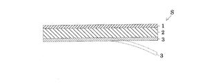
- the pressure-sensitive adhesive sheet S is a sheet having a resin layer 2 laminated on a reinforcing layer 1.
- a separator 3 larger than the shape of the resin layer 2 is attached to the opposite side of the resin layer 2.
- the reinforcing layer 1 provides, for example, toughness to the resin layer 2 that foams by heating.
- Examples of the reinforcing layer 1 include glass cloth, resin glass cloth, synthetic resin nonwoven fabric, metal foil, and carbon fiber.
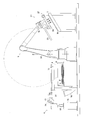
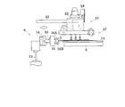
- FIG. 1 is a front view showing an overall configuration of an adhesive sheet pasting apparatus according to one embodiment of the present invention.
- This pasting device is composed of a sheet supply unit 4, a peeling table 5, a peeling unit 6, a holding table 7, a pasting mechanism 8, and the like.
- the sheet supply unit 4 is configured by stacking and storing an adhesive sheet S in a stocker 9 installed within a turning radius in which the robot 20 described later can move.
- the peeling table 5 includes a detachable support plate 11 thereon.
- the support rate 11 is flat so as to hold the entire surface of the adhesive sheet S.
- the tip of the support plate 11 has a roundness.
- the peeling unit 6 includes an elevating mechanism 12 composed of an air cylinder, a swing arm 15 attached to the tip of a rod 13 of the air cylinder, and pivotally supported by a movable base 14 that moves up and down.
- the swing arm 15 includes a pair of movable pieces 16 ⁇ / b> A and 16 ⁇ / b> B and a grip 16.
- the swing arm 15 is configured to be able to swing and stop and adjust the swing speed by pressure control.
- the movable pieces 16A and 16B are configured to relatively move toward or away from each other by pressure control.
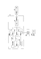
- the elevating mechanism 12, the swing arm 15, and the gripping portion 16 are connected to the primary pressure regulator 18 and the compressed air source 19 via electromagnetic valves 17 ⁇ / b> A, 17 ⁇ / b> B, and 17 ⁇ / b> C, respectively. ing.
- the primary pressure regulator 18 outputs the pressure of the air supplied from the compressed air source 19 as a predetermined stable secondary pressure.
- the holding table 7 is configured to hold the workpiece W by suction or clamping.
- the pasting mechanism 8 includes a transport robot 20 and a pasting unit 21.
- the robot 20 is configured to be capable of pivoting around the vertical axis P and pivoting each arm for each of a plurality of joints. Also.
- a holding frame 22 is provided at the end of the arm so as to turn the sticking unit 21 around the axis Q by a bearing.
- the robot 20 corresponds to the transport mechanism of the present invention.
- the holding frame 22 is provided with a guide rail 23 for reciprocating a movable base 25 of a pasting unit 21 described later.
- a stopper for preventing dropping is provided on one end side of the guide rail 23.
- a lock mechanism 24 that engages and fixes the movable base 10 is provided on the other end side of the guide rail 22.
- the pasting unit 21 includes a movable base 25, a holding unit 26, a pasting roller 27, and the like.
- the movable table 25 includes a holding unit 26.
- the holding part 26 includes a plurality of suction pads 28 urged downward by an elastic body such as a spring.
- the suction pads 28 are arranged in a two-dimensional array at a predetermined pitch so that, for example, when the adhesive sheet S is placed on the workpiece W, a uniform pressure acts on the adhesive sheet S.
- the suction surface of the suction pad 28 is formed with an arc-shaped convex part having a coaxial core.
- the convex portion is set to a height that fits in the concave portion of the suction pad 28. Therefore, the convex portion prevents the adhesive sheet S from being drawn into the suction pad 28.
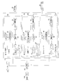
- suction pad 28 is connected in the order of an externally connected vacuum source 30, a primary pressure regulator 31, a pressure conversion regulator 32, and a solenoid valve 33 from the upstream side.
- the pressure conversion regulator 32 is equipped with a check valve 34.
- the primary pressure regulator 31 outputs the suction force from the vacuum source 30 as a predetermined stable secondary pressure.
- the pressure conversion adjuster 32 is constituted by a regulator, for example, and adjusts the preset secondary pressure (suction force) to be kept constant. That is, when the pressure conversion adjuster 32 detects a change in the suction force of the suction pad 28 by the sensor 35, the pressure conversion adjuster 32 obtains a deviation between the actual pressure of the detection signal and the set reference pressure, and the electromagnetic valve 33 or the check valve 34. Return to the set suction force by adjusting the opening.
- the sticking roller 27 is provided with a plurality of rows of brush hairs 40 linearly planted in the axial direction of the cylindrical roller at predetermined intervals.
- the affixing roller 27 is provided at the tip of the swing arm 42 connected to the rod tip of the cylinder 41 fixed to the movable base 25.
- the affixing roller 27 is configured to be rotationally driven by, for example, an air motor 43 that is a driving device.
- the drive device is not limited to an air motor, and a direct motor, a pulse motor, or the like can also be used.
- the pasting roller 20 corresponds to the brush roller of the present invention.
- the air motor 43 is connected in the order of an externally connected compressed air source 40, a primary pressure regulator 44, a pressure conversion regulator 45, and a solenoid valve 46 from the upstream side.
- the pressure conversion regulator 45 is equipped with a check valve 47.
- the pressure conversion adjuster 45 is constituted by a regulator, for example, and adjusts the preset secondary pressure (compressed air) so as to keep it constant. That is, the pressure conversion adjuster 45 measures a change in the rotation speed of the sticking roller 27 with a sensor such as a speedometer 48, and obtains a deviation between the rotation speed obtained from the measurement signal and the set reference speed. 46 and the check valve 47 are adjusted to keep the rotation speed constant.
- the swing arm 42 swings, stops, and swing speed can be adjusted by pressure control of the cylinder.
- the compressed air source 40, the primary pressure regulator 51, and the pressure conversion regulator that are externally connected from the upstream side. 52 and solenoid valve 53 are connected in this order.
- the pressure conversion regulator 52 is equipped with a check valve 54.
- the pressure conversion adjuster 52 is composed of, for example, a regulator, and adjusts the preset secondary pressure so as to be kept constant. That is, the pressure conversion adjuster 52 detects the rotational resistance acting on the affixing roller 27 with a sensor such as a potentiometer 55, obtains a deviation between the measured value of the rotational resistance and a predetermined reference value, and responds to the deviation. By adjusting the opening degree of the electromagnetic valve 23 and the check valve 24, the pressing of the sticking roller 27 is kept constant.
- predetermined conditions are input to the control unit 60 from the operation panel 100 shown in FIGS. 2 and 3, and the peeling condition and the pasting condition of the adhesive sheet S are set.
- the tension that can be peeled from the pressure-sensitive adhesive sheet S without breaking the separator 3 attached to the pressure-sensitive adhesive sheet S to be used is obtained. That is, a peeling speed when the separator 3 is broken in the process of folding the separator 3 by the support plate 11 and peeling is obtained in advance by experiments and simulations, and the allowable peeling speed is set in the controller 60 from the speed.
- the peeling allowance speed is obtained from the lowering speed of the elevating mechanism 12 and the swing lowering speed of the swing arm 15. It sets so that the sticking unit 21 provided with the holding
- the lock mechanism 24 of the sticking unit 21 is released and the sticking unit 21 is set to travel on the guide rail 23 in a free state.
- the weight of the affixing unit 21 and the downward urging force by the suction pad 28 are set to act.
- the hardware configuration such as the height of the gripping portion 16 of the peeling unit 6 is set. For example, considering the amount of deflection of the adhesive sheet S sent out from the support plate 11, the tip of the separator 3 attached to the adhesive sheet S enters between the movable pieces 16 ⁇ / b> A and 16 ⁇ / b> B waiting in front. The height of the grip 16 is adjusted.
- the affixing conditions are set so that the rotation speed of the affixing roller 27 is faster than the moving speed of affixing the adhesive sheet S to the workpiece W while moving the affixing unit 21 by the operation of the arm of the robot 20.
- the pasting speed and the rotational speed are stored in advance in the control unit 60 as optimum recipes through experiments and simulations according to the adhesive sheet S and the pasting roller 27 to be used.
- initial setting is performed so that the pressing of the sticking roller 27 at the sticking start position of the adhesive sheet S becomes a predetermined pressure.
- the robot 20 moves the sticking unit 21 holding the adhesive sheet S by suction onto the support plate 11 and places the adhesive sheet S thereon. Thereafter, as shown in FIG. 5, the affixing unit 27 adsorbs the pressure-sensitive adhesive sheet S while adsorbing the pressure-sensitive adhesive sheet S and applies an appropriate load to the pressure-sensitive adhesive sheet S by the elastic bias of the suction pad 28. Slide.
- the separator 3 When the separator 3 reaches a predetermined position, as shown in FIG. 6, the movable pieces 16A and 16B are closed and the leading end portion of the separator 3 is gripped. As shown in FIG. 15 is swung down. By lowering the swing arm 15 in a direction crossing the horizontally conveyed adhesive sheet S, the separator 3 is folded and peeled off at the tip of the support plate 11. At this time, the angle ⁇ formed by the separator 3 folded back with respect to the longitudinal horizontal axis of the adhesive sheet S is maintained at an acute angle.
- the affixing unit 21 moves horizontally while adsorbing and holding the adhesive sheet S.
- the separator 3 peeled from the adhesive sheet S is collected by a suction device 70 disposed below the swing arm 15.
- the robot 20 moves to the holding table 7 while holding the adhesive sheet S on the holding unit 26 of the sticking unit 21 by suction.
- the sticking unit 21 is inclined and slid on the guide rail 23. That is, the movable base 25 of the pasting unit 21 that has moved to the end of the guide rail 23 is fixed by the lock mechanism 24.
- the robot 20 When the affixing unit 21 reaches a predetermined position of the workpiece W on the holding table 7, the robot 20 lowers the affixing unit 21 and places the adhesive sheet S adsorbed by the adsorption pad 28 on the workpiece W.
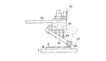
- the robot 20 moves the sticking unit 21 to a position where the suction pad 28 that has released the suction does not come into contact with the adhesive sheet S. Thereafter, the control unit 60 operates the swing arm 41 by the cylinder 41 and lowers the sticking roller 27 to the sticking position as shown in FIG. At the same time, the affixing roller 27 is rotated.
- the robot 20 moves the pasting unit 21 so that the pasting roller 27 intersects the workpiece W as shown in FIG. At this time, the adhering roller 27 presses the adhesive sheet S while adhering to the work W while rotating at a speed faster than the moving speed.
- the rotation resistance acting on the pasting roller 27 is detected by the potentiometer 55.
- the control unit 70 compares the measured value of the rotation resistance with the reference value, changes the swing angle of the swing arm 42 by the cylinder 41 according to the obtained deviation, adjusts the height of the sticking roller 27, and sticks the sticking roller 27.
- the pressure on the pressure-sensitive adhesive sheet S is controlled to be constant.
- control unit 60 monitors the rotational speed of the sticking roller 27 with the speedometer 48 and controls the rotational speed to be kept constant.
- the control unit 60 stops the rotation of the affixing roller 27 and operates the robot 20 to affix the adhesive sheet S to the next workpiece W.
- the workpiece W to which the adhesive sheet S is attached is carried out of the holding table 7. This completes one round of operation of attaching the adhesive sheet to the workpiece W, and thereafter the same operation is repeated.
- the brush bristles provided in a plurality of rows at predetermined intervals on the surface of the sticking roller 27 follow the workpiece surface while bending on the surface of the adhesive sheet S, and multiple times while slipping. The same part is pressed over That is, the pressure per unit area to the adhesive sheet S by the sticking roller 27 can be increased. Moreover, since the rotation resistance of the sticking roller 27 is detected and the height is adjusted, the rotation of the sticking roller 27 does not stop. Therefore, the pressure-sensitive adhesive sheet S can be attached to the work W while applying a substantially uniform pressure to the entire surface of the work, so that the pressure-sensitive adhesive sheet S can be reliably adhered to the surface of the work W.
- the present invention can also be implemented in the following forms.
- the pasting unit 21 is not limited to the form attached to the robot 20.
- work the guide rail provided in the ceiling may be sufficient. Therefore, the holding table 7 that holds the workpiece W is not limited to the one having the inclined mounting surface, and may be horizontal.
- the pasting unit 21 may be fixedly arranged so that the holding table 7 moves.
- the pasting roller 27 of the above embodiment is provided with a plurality of rows of bristle hairs 40 spirally planted on the surface of the roller at predetermined intervals on the surface. Also good.
- the affixing roller 27 may be configured such that the brush hairs 40 become longer from both ends toward the center of the rotation shaft.
- the sticking roller 27A in which the brush hairs 40 are spirally planted When the sticking roller 27A in which the brush hairs 40 are spirally planted is used, a more uniform pressing force can be applied as compared to the sticking roller 27 in which the brush hairs 40 are planted directly. That is, when the affixing roller 27 provided with the straight brush hairs 40 is used, when the next row of brush hairs comes into contact with the workpiece W from the brush hair that is in contact with the workpiece W, the brushes are changed according to the pitch between the rows. The hair 40 intermittently collides with the workpiece W. In other words, a light impact is applied to the adhesive sheet S.
- the bristles 40 press the adhesive sheet S while being continuously bent along the spiral. Therefore, a uniform pressing always acts on the adhesive sheet S.
- the affixing roller 27B may be inclined and rolled with respect to the surface of the workpiece W. That is, for example, when the surface of the workpiece W is curved, the pressure applied to the pressure-sensitive adhesive sheet S can be kept substantially constant by setting the curvature to approximately the same as the curvature. Moreover, when the workpiece
- the height adjustment of the affixing roller 27 is not limited to the above form.
- the mapping data of the surface shape of the workpiece W may be acquired in advance, and the height of the sticking roller 27 may be adjusted based on the position information of the mapping data and the position information of the sticking roller 27 that moves.
- the present invention is suitable for accurately sticking an adhesive sheet on the surface of a workpiece having irregularities.
Landscapes
- Engineering & Computer Science (AREA)
- Mechanical Engineering (AREA)
- Manufacturing & Machinery (AREA)
- Chemical & Material Sciences (AREA)
- Crystallography & Structural Chemistry (AREA)
- Inorganic Chemistry (AREA)
- Coating Apparatus (AREA)
- Folding Of Thin Sheet-Like Materials, Special Discharging Devices, And Others (AREA)
- Lining Or Joining Of Plastics Or The Like (AREA)
- Labeling Devices (AREA)
Abstract
貼付けローラは、表面に直線状または螺旋状に植設されたブラシ毛をローラ表面に所定間隔をおいて複数列で設けられている。当該貼付けローラと被着体であるワークを交差させるように相対的に移動させながら粘着シーSをワークに貼り付ける。この貼り付け過程において、粘着シートへの押圧が一定となるように、当該ワークの表面形状に応じて当該貼付けローラの回転速度を調整する。
Description
本発明は、自動車を含む輸送機械および各種産業機械の鋼板に貼り付けて補強或いは制振するための粘着シートの貼付け方法および粘着シート貼付け装置に関する。
近年、自動車などの車両の重量を軽量化するために鋼板を薄型化する傾向にある。当該薄型化に伴って鋼板の剛性が低下している。また、薄型化された鋼板は、路面の凹凸やエンジンの振動および騒音が伝わりやすい。したがって、鋼板の剛性を補うための樹脂シートまたは振動などを制振するための樹脂シートが提案されている(特許文献1を参照)。
また、補強用の樹脂シートに添設された離型紙を剥離し、自動車のボディの側部外板を構成するサイドメンバーへの貼り付けを自動で行う装置が提案されている。当該装置は、次のようにして樹脂シートの貼り付けを行っている。
先ず、樹脂シートから離型紙を剥離する。すなわち、搬送ベルトの前方に配備したガイド部材の先端から突き出た樹脂シートより大きい離型紙に離型紙加圧装置のアームに備わった加圧ローラを押し当てながら揺動下降させる。当該加圧ローラの下降先で搬送ベルトと協働して離型紙の先端を把持する。そのままの状態で搬送ベルトを継続的に駆動させることにより、樹脂シートをガイド部材から送り出しながらから離型紙を剥離する。
離型紙の剥離された樹脂シートは、ガイド部材の前方に配備されたシート支持体に載置される。当該シート支持体上の樹脂シートに真空吸着装置のパッドで押し当てて吸着し、自動車のサイドメンバーまで搬送して載置する。その後、円柱状の押圧ローラを樹脂シート上で転動させてサイドメンバーに貼り付ける(特許文献2を参照)。
しかしながら、従来の粘着シートの貼り付け方法では、次のような問題が生じている。自動車のボディの側部外板を構成するサイドメンバーは、側部外板に剛性を持たせるために湾曲または凹凸が形成されている。また、樹脂シートは、通常の粘着テープに比べて厚い。それ故に円筒状または円柱状のローラを利用した場合、ローラが凹凸部分で偏当たりをする。したがって、樹脂シートを外板に密着させることができないといった問題が生じている。
本発明はこのような事情に鑑みてなされたものであって、輸送機械などの凹凸や湾曲した鋼板に粘着シートを密着させることのできる粘着シート貼付け方法および粘着シート貼付け装置を提供することを主たる目的とする。
この発明は、このような目的を達成するために、次のような構成をとる。
すなわち、ワークに粘着シートを貼り付ける粘着シート貼付け方法であって、
回転駆動するブラシローラと前記ワークを交差させるように相対的に移動させながら粘着シートを当該ワークに貼り付ける過程で、当該ワークの表面形状に応じて当該ブラシローラの回転速度を調整する
ことを特徴とする。
回転駆動するブラシローラと前記ワークを交差させるように相対的に移動させながら粘着シートを当該ワークに貼り付ける過程で、当該ワークの表面形状に応じて当該ブラシローラの回転速度を調整する
ことを特徴とする。
この方法によれば、ブラシローラのブラシ毛が、ワークの表面の形状に追従するように撓りながら粘着シートを押圧する。したがって、凹凸または湾曲するワークの表面に略均一な押圧で粘着シートを貼り付けることができる。
上記実施形態において、ワークとブラシローラの相対的な移動速度よりも早い速度でブラシローラの回転速度を調整することが好ましい。
この方法によれば、ブラシ毛が、粘着シートの表面で撓りながらスリップする。すなわち、ブラシローラによる粘着シートへの単位面積当たりの押圧を大きくしつつも、ワークとブラシローラの相対的な移動を停止させることがない。したがって、粘着シートをワークの表面に確実に密着させることができる。
また、上記実施形態において、粘着シートを貼り付ける過程で、ブラシローラの回転抵抗を検出し、当該検出結果に応じてブラシローラの高さを調整することが好ましい。
この方法によれば、ワークの表面形状にブラシロールを精度よく追従させることができる。その結果、ブラシローラの回転を停止させることなく、均一な押圧を粘着シートに作用させることができる。
なお、上記の各実施形態において、次のようなブラシローラが利用される。
例えば、回転軸に沿って直線状に植設したブラシ毛をローラの表面に所定間隔をおいて複数列で設けられてなるブラシローラ。
回転軸に沿って螺旋状に植設したブラシ毛をローラの表面に所定間隔をおいて複数列で設けられてなるブラシローラ。
回転軸の端部から中央に向かって山形になるようブラシ毛をローラの表面に植設してなるブラシローラ。なお、当該ブラシローラを利用する場合、ワーク表面の凹凸に応じてブラシローラを傾斜させることが好ましい。
この方法によれば、ワーク表面の起立部の角部にブラシ毛を偏当たりさせたり、或いは湾曲形状に追従させたりしやすくなる。
また、この発明は、このような目的を達成するために、次のような構成をとる。
すなわち、ワークに粘着シートを貼り付ける粘着シート貼付け装置であって、
前記ワークを保持する保持テーブルと、
ブラシローラを回転駆動させながら前記粘着シートをワークに貼り付ける貼付けユニットと、
前記保持テーブルとブラシローラを交差させるように相対的に移動させる駆動機構と、
前記ワークの表面形状に応じて保持テーブルとブラシロールの相対的な移動速度よりも早い速度でブラシローラの回転速度を調整する速度制御部と、
を備えたことを特徴とする。
前記ワークを保持する保持テーブルと、
ブラシローラを回転駆動させながら前記粘着シートをワークに貼り付ける貼付けユニットと、
前記保持テーブルとブラシローラを交差させるように相対的に移動させる駆動機構と、
前記ワークの表面形状に応じて保持テーブルとブラシロールの相対的な移動速度よりも早い速度でブラシローラの回転速度を調整する速度制御部と、
を備えたことを特徴とする。
この構成によれば、ワークに粘着シートを貼り付ける過程で、ワークの表面形状に応じてブラシローラの回転速度が移動速度よりも早く調整される。したがって、上記方法を好適に実施することができる。
なお、当該構成において、ブラシローラの回転抵抗を検出する検出器と、
ブラシローラを昇降させる昇降機構と、
検出器の検出結果に応じて昇降機構を操作し、ブラシローラの高さを調整する高さ制御部を備えることが好ましい。
ブラシローラを昇降させる昇降機構と、
検出器の検出結果に応じて昇降機構を操作し、ブラシローラの高さを調整する高さ制御部を備えることが好ましい。
この構成によれば、ワーク表面の凹凸形状に応じてブラシローラが昇降させられる。したがって、粘着シートに作用する押圧を略一定に保つことができる。
さらに、上記構成において、ブラシローラを傾斜させる揺動機構を備えることが好ましい。
この構成によれば、ワーク表面の起立部の角部にブラシ毛を偏当たりさせたり、或いは湾曲形状に追従させたりしやすくなる。
本発明の粘着シート貼付け方法および粘着シート貼付け装置によれば、凹凸を有するワークの表面に粘着シートを精度よく貼り付けることができる。
6 … 剥離ユニット
7 … 保持テーブル
8 … 貼付け機構
21 … 貼付けユニット
26 … 保持部
27 … 貼付けローラ
28 … 吸着パット
41 … シリンダ
42 … 揺動アーム
43 … エアーモータ
S … 粘着シート
W … ワーク
7 … 保持テーブル
8 … 貼付け機構
21 … 貼付けユニット
26 … 保持部
27 … 貼付けローラ
28 … 吸着パット
41 … シリンダ
42 … 揺動アーム
43 … エアーモータ
S … 粘着シート
W … ワーク
以下、図面を参照して本発明の一実施例説明する。なお、本実施例では、自動車のボンネットやドアなどの鋼板を補強する補強用鋼板樹脂組成物からなる粘着シートを貼り付ける場合を例にとって説明する。
<粘着シート>
粘着シートSは、図4に示すように、補強層1に樹脂層2が積層された枚葉体である。当該樹脂層2の反対側には、当該樹脂層2の形状よりも大きいセパレータ3が添設されている。
粘着シートSは、図4に示すように、補強層1に樹脂層2が積層された枚葉体である。当該樹脂層2の反対側には、当該樹脂層2の形状よりも大きいセパレータ3が添設されている。
補強層1は、例えば、加熱による発泡する樹脂層2に靱性を付与するものである。補強層1としては、例えば、ガラスクロス、樹脂ガラスクロス、合成樹脂不織布、金属箔、カーボンファイバなどが挙げられる。
<粘着シート貼付け装置>
図1は、この発明の一実施例に係り、粘着シート貼付け装置の全体構成を示した正面図である。
図1は、この発明の一実施例に係り、粘着シート貼付け装置の全体構成を示した正面図である。
この貼付け装置は、シート供給部4、剥離テーブル5、剥離ユニット6、保持テーブル7および貼付け機構8などから構成されている。
シート供給部4は、後述するロボット20の移動可能な旋回半径内に設置されたストッカ9に粘着シートSを積層収納して構成されている。
剥離テーブル5は、その上に着脱可能な支持プレート11を備えている。支持レート11は、粘着シートSの全面を保持するように扁平面になっている。当該支持プレート11の先端は、丸みを有している。
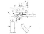
剥離ユニット6は、図1および図2に示すように、エアーシリンダからなる昇降機構12、当該エアーシリンダのロッド13の先端に装着され、昇降する可動台14に軸支された揺動アーム15および当該揺動アーム15の先端に備わった一対の可動片16A、16Bからなる把持部16などから構成されている。
揺動アーム15は、圧力制御により揺動および停止並びに揺動速度の調整が可能に構成されている。また、可動片16A、16Bも同様に圧力制御により相対的に接近または離反移動するよう構成されている。
昇降機構12、揺動アーム15および把持部16は、図2に示すように、それぞれが電磁弁17A、17B、17Cを介してして1次圧力調整機18および圧縮エアー源19に連通接続されている。
1次圧力調整機18は、圧縮エアー源19から供給されるエアーの圧力を所定の安定した2次圧力にして出力する。
保持テーブル7は、ワークWを吸着またはクランプによって保持するよう構成されている。
貼付け機構8は、搬送用のロボット20および貼付けユニット21などから構成されている。
ロボット20は、縦軸P周りに旋回および複数関節ごとに各アームを枢動可能に構成されている。また。アーム先端にはベアリングによって貼付けユニット21を軸Q周りに旋回させるよう保持フレーム22を備えている。なお、ロボット20は、本発明の搬送機構に相当する。
保持フレーム22は、後述する貼付けユニット21の可動台25を往復移動させるガイドレール23が設けられている。また、ガイドレール23の一端側に落下防止用のストッパが設けられている。さらに、ガイドレール22の他端側には、可動台10に係合して固定するロック機構24が備わっている。
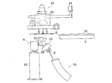
貼付けユニット21は、図1および図3に示すように、可動台25、保持部26および貼付けローラ27などから構成されている。
可動台25は、保持部26を備えている。保持部26は、バネなどの弾性体によって下向きに付勢された複数本の吸着パット28を備えている。吸着パット28は、例えば、粘着シートSをワークWに載置するときに、当該粘着シートSに均一な押圧が作用するよう所定ピッチで2次元アレー状に配備されている。
当該吸着パット28の吸着面は、同軸芯を有する円弧状の凸部が形成されている。当該凸部は、吸着パット28の凹部内に収まる高さに設定されている。したがって、当該凸部は、吸着パット28に粘着シートSが引き込まれるのを防止する。
また、吸着パット28は、上流側から外部接続の真空源30、1次圧力調整機31、圧力変換調整機32および電磁弁33の順に接続されている。なお、圧力変換調整機32には、逆止弁34が装備されている。
1次圧力調整機31は、真空源30による吸引力を所定の安定した2次圧力にして出力する。
圧力変換調整器32は、例えばレギュレータで構成されており、予め設定した2次圧力(吸引力)を一定に保つように調整する。すなわち、圧力変換調整器32は、吸着パット28の吸引力の変化をセンサ35で検知しとき、当該検知信号の実圧力と設定された基準圧力の偏差を求め、電磁弁33や逆止弁34の開度を調整することによって設定吸引力に戻す。
貼付けローラ27は、図8および図9に示すように、円柱状のローラの軸方向に直線状に植設されたブラシ毛40をその表面に所定間隔をおいて複数列で設けられている。また、貼付けローラ27は、可動台25に固定されたシリンダ41のロッド先端に連結された揺動アーム42の先端に備わっている。貼付けローラ27は、駆動装置である例えばエアーモータ43によって回転駆動するように構成されている。なお、駆動装置は、エアーモータに限定されずダイレクトモータやパルスモータなども利用することができる。なお、貼付けローラ20は、本発明のブラシローラに相当する。
エアーモータ43は、上流側から外部接続の圧縮エアー源40、1次圧力調整機44、圧力変換調整機45および電磁弁46の順に接続されている。なお、圧力変換調整機45には、逆止弁47が装備されている。
圧力変換調整器45は、例えばレギュレータで構成されており、予め設定した2次圧力(圧縮エアー)を一定に保つように調整する。すなわち、圧力変換調整器45は、貼付けローラ27の回転数の変化を、例えば速度計48などのセンサによって計測し、当該計測信号から求まる回転速度と設定された基準速度の偏差を求め、電磁弁46や逆止弁47の開度を調整することによって回転速度を一定に保つよう構成されている。
揺動アーム42は、シリンダの圧力制御により揺動および停止並びに揺動速度の調整が可能となるように、上流側から外部接続の圧縮エアー源40、1次圧力調整機51、圧力変換調整機52および電磁弁53の順に接続されている。なお、圧力変換調整機52には、逆止弁54が装備されている。
圧力変換調整器52は、例えばレギュレータで構成されており、予め設定した2次圧力を一定に保つように調整する。すなわち、圧力変換調整器52は、貼付けローラ27に作用する回転抵抗を、例えばポテンショメータ55などのセンサによって検知し、当該回転抵抗の実測値と予め決めた基準値の偏差を求め、当該偏差に応じて電磁弁23や逆止弁24の開度を調整することによって貼付けローラ27の押圧を一定に保つよう構成されている。
次に、上述の実施例装置を用いて、ワークに粘着シートを貼り付ける一巡の動作を図2から図9に基づいて説明する。
先ず、図2および図3に示す操作パネル100から所定条件を制御部60に入力し、粘着シートSの剥離条件および貼り付け条件を設定する。
剥離条件は、使用する粘着シートSに添設されたセパレータ3が破断されることなく粘着シートSから剥離可能な張力を求める。すなわち、支持プレート11でセパレータ3を折り返して剥離する過程でセパレータ3が破断するときの剥離速度を実験やシミュレーションによって予め求め、当該速度から剥離許容速度を制御部60に設定する。例えば、当該剥許容速度は、昇降機構12の下降速度と揺動アーム15の揺動下降速度から求める。当該剥離速度と略同じ速度で粘着シートSを吸着保持する保持部26を備えた貼付けユニット21を水平移動させるように設定する。本実施例では、貼付けユニット21のロック機構24を解除して貼付けユニット21が、フリーな状態でガイドレール23を走行するように設定される。換言すれば、セパレータSの剥離時に貼付けユニット21の自重および吸着パット28による下向きの付勢力が作用するよう設定される。
次に、剥離ユニット6の把持部16の高さなどハード構成の設定をする。例えば、支持プレート11から送り出される粘着シートSの撓み量を考慮し、粘着シートSに添設されたセパレータ3の先端部分が、前方で待機している可動片16A,16Bの間に進入するよう把持部16の高さを調整する。
次に、貼付け条件は、ロボット20のアームの動作によって貼付けユニット21を移動させながらワークWに粘着シートSを貼り付ける移動速度よりも貼付けローラ27の回転速度が早くなるよう設定される。貼り付け速度および回転速度は、使用する粘着シートSおよび貼付けローラ27に応じて実験やシミュレーションによって最適条件をレシピとして制御部60に予め記憶されている。
また、粘着シートSの貼り付け開始位置での貼付けローラ27の押圧が所定の押圧になるように初期設定する。
各種初期条件の設定が完了すると、装置を作動させる。先ず、ロボット20が、ストッカ9の上まで貼付けユニット21を移動させる。ロボット20は、貼付けユニット21を所定高さまで下降させる。保持部26の吸着パット28が、ストッカ9内に積層収納されている粘着シートSを吸着保持する。
ロボット20は、粘着シートSを吸着保持している貼付けユニット21を支持プレート11上に移動させて粘着シートSを載置する。その後、貼付けユニット27は、図5に示すように、粘着シートSを吸着したまま自重および吸着パット28の弾性付勢により、粘着シートSに適度の荷重をかけながら支持プレート11上で粘着シートSをスライドさせてゆく。
支持プレート11の先端から粘着シートSが突き出ると、前方で待機している開放状態にある可動片16A、16Bの間にセパレータ3の先端部分が進入してゆく。
セパレータ3が所定位置まで達すると、図6に示すように、可動片16A、16Bを閉じてセパレータ3の先端部分を把持し、図7に示すように、昇降機構12を下降させつつ揺動アーム15を揺動下降する。水平搬送される粘着シートSと交差する方向に揺動アーム15を下降させることにより、セパレータ3が支持プレート11の先端で折り返されて剥離されてゆく。このとき、粘着シートSの長手水平軸に対して折り返されたセパレータ3のなす角度αは、鋭角に保たれている。
このセパレータ3の剥離動作に同期して、貼付けユニット21は、粘着シートSを吸着保持しまま、水平移動してゆく。
粘着シートSから剥離されたセパレータ3は、揺動アーム15の下方に配置された吸引装置70によって回収される。
ロボット20は、貼付けユニット21の保持部26に粘着シートSを吸着保持させたまま保持テーブル7まで移動する。この移動過程で、貼付けユニット21を傾斜姿勢にしてガイドレール23上でスライドさせる。つまり、ガイドレール23の端部に移動した貼付けユニット21の可動台25をロック機構24によって固定する。
貼付けユニット21が保持テーブル7上のワークWの所定位置に達すると、ロボット20は、貼付けユニット21を下降させ、吸着パット28によって吸着されている粘着シートSをワークWに載置する。
ロボット20は、吸着を解除した吸着パット28が粘着シートSに接触しない位置まで貼付けユニット21を移動させる。その後、制御部60は、シリンダ41によって揺動アーム41を操作させ、図8に示すように、貼付けローラ27を貼付け位置まで下降させる。同時に貼り付けローラ27を回転させる。
貼付けローラ27が貼り付け位置に達すると、ロボット20は、図9に示すように、ワークW上に貼付けローラ27を交差させるよう貼付けユニット21を移動させる。このとき、貼付けローラ27は、移動速度よりも早い速度で回転しながら粘着シートSを押圧してワークWに貼り付けゆく。
この貼り付け過程で、ポテンショメータ55によって貼付けローラ27に作用する回転抵抗が検出される。制御部70は、回転抵抗の実測値と基準値を比較し、求まる偏差に応じてシリンダ41によって揺動アーム42の揺動角度を変更させて貼付けローラ27の高さを調整し、貼付けローラ27による粘着シートSへの押圧が一定となるようコントロールしている。
また、制御部60は、速度計48によって貼付けローラ27の回転速度をモニタし、回転速度が一定に保たれるようにコントロールしている。
貼付けローラ27が終端位置に達すると、制御部60は、貼付けローラ27の回転を停止させるとともに、次のワークWに粘着シートSを貼り付けるようロボット20を操作する。同時に粘着シートSの貼り付けられたワークWは、保持テーブル7から搬出される。以上でワークWに粘着シートを貼り付ける一巡の動作が終了し、以後同じ動作が繰り返される。
上記実施例装置によれば、貼付けローラ27の表面に所定間隔をおいて複数列で設けられたブラシ毛が、粘着シートSの表面で撓りながらワーク表面に追従するとともに、スリップしながら複数回に亘って同一箇所を押圧する。すなわち、貼付けローラ27による粘着シートSへの単位面積当たりの押圧を大きくすることができる。また、貼付けローラ27の回転抵抗を検出して高さ調整しているので、貼付けローラ27の回転が停止することがない。したがって、ワーク全面に略均一な押圧を付与しながら粘着シートSをワークWに貼り付けることができるので、粘着シートSをワークWの表面に確実に密着させることができる。
なお、本発明は以下のような形態で実施することもできる。
(1)上記実施例装置において、貼付けユニット21は、ロボット20に装着された形態に限定されな。例えば、天井に設けられたガイドレールを走行するよう懸垂支持しれた昇降機構の先端に装着された構成であってもよい。したがって、ワークWを保持する保持テーブル7は、載置面が傾斜したものに限定されず、水平であってもよい。
また、貼付けユニット21を固定配備し、保持テーブル7が移動するように構成してもよい。
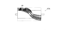
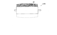
(2)上記実施例の貼付けローラ27は、図10に示すように、ローラ表面に螺旋状に植設されたブラ毛40をその表面に所定間隔をおいて複数列で設けたものであってもよい。或いは、貼付けローラ27は、図11に示すように、両端から回転軸の中心に向かうについてブラシ毛40が長くなるよう構成したものであってもよい。
螺旋状にブラシ毛40を植設した貼付けローラ27Aを利用した場合、直接状にブラシ毛40を植設した貼付けローラ27に比べて、より均一な押圧力を作用させることができる。すなわち、直線状のブラシ毛40を設けた貼付けローラ27を利用した場合、ワークWに接触しているブラシ毛から次のブラシ毛の列がワークWに接触するときに、列同士のピッチによってブラシ毛40が間欠的にワークWに衝突する。換言すれば、粘着シートSに軽く衝撃を加えることになる。
これに対して、螺旋状のブラシ毛40を設けた貼付けローラ27Bを利用した場合、螺旋に沿ってブラシ毛40が連続的に撓りながら粘着シートSを押圧する。したがって、常に均一な押圧が粘着シートSに作用する。
長さの異なるブラシ毛が植設された貼付けローラ27Bを利用する場合、ワークWの表面に対して貼付けローラ27Bを斜めにして転動させてもよい。すなわち、例えば、ワークWの表面が湾曲している場合、当該曲率と略同程度の曲率にすることにより、粘着シートSに作用させる圧を略一定に保つことができる。また、ワークWが表面に凹凸を有する場合、当該凹凸の形状に応じてブラシ毛を偏って当てることにより、凹凸の角部に粘着シートSを密着させることができる。
(3)上記実施例装置において、貼付けローラ27の高さ調整は、上記形態に限定されない。例えば、ワークWの表面形状のマッピングデータを予め取得し、当該マッピングデータの位置情報と移動する貼付けローラ27の位置情報に基づいて、当該貼り付けローラ27の高さを調整してもよい。
以上のように、本発明は、凹凸を有するワークの表面に粘着シートを精度よく貼り付けるのに適している。
Claims (9)
- ワークに粘着シートを貼り付ける粘着シート貼付け方法であって、
回転駆動するブラシローラと前記ワークを交差させるように相対的に移動させながら粘着シートを当該ワークに貼り付ける過程で、当該ワークの表面形状に応じて当該ブラシローラの回転速度を調整する
ことを特徴とする粘着シート貼付け方法。 - 請求項1に記載の粘着シート貼付け方法において、
前記ワークとブラシローラの相対的な移動速度よりも早い速度でブラシローラの回転速度を調整する
ことを特徴とする粘着シート貼付け方法。 - 請求項1または請求項2に記載の粘着シート貼付け方法において、
前記粘着シートを貼り付ける過程で、ブラシローラの回転抵抗を検出し、当該検出結果に応じてブラシローラの高さを調整する
ことを特徴とする粘着シート貼付け方法。 - 請求項1ないし請求項3のいずれかに記載の粘着シート貼付け方法において、
前記ブラシローラは、回転軸に沿って直線状に植設したブラシ毛をローラの表面に所定間隔をおいて複数列で設けられてなる
ことを特徴とする粘着シート貼付け方法。 - 請求項1ないし請求項3のいずれかに記載の粘着シート貼付け方法において、
前記ブラシローラは、回転軸に沿って螺旋状に植設したブラシ毛をローラの表面に所定間隔をおいて複数列で設けられてなる
ことを特徴とする粘着シート貼付け方法。 - 請求項1ないし請求項5のいずれかに記載の粘着シート貼付け方法において、
前記ブラシローラは、回転軸の端部から中央に向かって山形になるようブラシ毛をローラの表面に植設してなり、
前記ワーク表面の凹凸に応じてブラシローラを傾斜させる
ことを特徴とする粘着シート貼付け方法。 - ワークに粘着シートを貼り付ける粘着シート貼付け装置であって、
前記ワークを保持する保持テーブルと、
ブラシローラを回転駆動させながら前記粘着シートをワークに貼り付ける貼付けユニットと、
前記保持テーブルとブラシローラを交差させるように相対的に移動させる駆動機構と、
前記ワークの表面形状に応じて保持テーブルとブラシロールの相対的な移動速度よりも早い速度でブラシローラの回転速度を調整する速度制御部と、
を備えたことを特徴とする粘着シート貼付け装置。 - 請求項7に記載の粘着シート貼付け装置おいて、
前記ブラシローラの回転抵抗を検出する検出器と、
前記ブラシローラを昇降させる昇降機構と、
前記検出器の検出結果に応じて昇降機構を操作し、ブラシローラの高さを調整する高さ制御部と、
を備えたことを特徴とする粘着シート貼付け装置。 - 請求項7または請求項8に記載の粘着シート貼付け装置おいて、
前記ブラシローラを傾斜させる揺動機構と、
を備えたことを特徴とする粘着シート貼付け装置。
Priority Applications (2)
| Application Number | Priority Date | Filing Date | Title |
|---|---|---|---|
| US15/126,788 US10131090B2 (en) | 2014-03-19 | 2015-03-18 | Adhesive sheet pasting method and adhesive sheet pasting apparatus |
| EP15765002.9A EP3120993B1 (en) | 2014-03-19 | 2015-03-18 | Adhesive sheet pasting method and adhesive sheet pasting apparatus |
Applications Claiming Priority (2)
| Application Number | Priority Date | Filing Date | Title |
|---|---|---|---|
| JP2014-056587 | 2014-03-19 | ||
| JP2014056587A JP6034324B2 (ja) | 2014-03-19 | 2014-03-19 | 粘着シート貼付け方法および粘着シート貼付け装置 |
Publications (1)
| Publication Number | Publication Date |
|---|---|
| WO2015141736A1 true WO2015141736A1 (ja) | 2015-09-24 |
Family
ID=54144700
Family Applications (1)
| Application Number | Title | Priority Date | Filing Date |
|---|---|---|---|
| PCT/JP2015/058085 WO2015141736A1 (ja) | 2014-03-19 | 2015-03-18 | 粘着シート貼付け方法および粘着シート貼付け装置 |
Country Status (4)
| Country | Link |
|---|---|
| US (1) | US10131090B2 (ja) |
| EP (1) | EP3120993B1 (ja) |
| JP (1) | JP6034324B2 (ja) |
| WO (1) | WO2015141736A1 (ja) |
Families Citing this family (6)
| Publication number | Priority date | Publication date | Assignee | Title |
|---|---|---|---|---|
| JP6855210B2 (ja) | 2015-11-24 | 2021-04-07 | 日東電工株式会社 | 粘着シート貼付け方法および粘着シート貼付け装置 |
| DE102017130704A1 (de) * | 2017-12-20 | 2019-06-27 | Multivac Marking & Inspection Gmbh & Co. Kg | Andruckrolle für eine Etikettiervorrichtung |
| DE102019000300A1 (de) * | 2018-09-19 | 2020-03-19 | Kiefel Gmbh | Greifer für eine vorrichtung zum formen und/oder kaschieren eines folienelements, drapierrahmen, vorrichtung zum formen und/oder kaschieren eines folienelements, anlage zum fertigen eines formteils oder eines kaschierten bauteils, verfahren zum formen oder kaschieren eines folienelements sowie verfahren zum fertigen eines kaschierten bauteils |
| CN109383018A (zh) * | 2018-09-30 | 2019-02-26 | 安顺云首创科技开发有限公司 | 一种手机屏幕贴片机 |
| KR102225463B1 (ko) * | 2020-10-12 | 2021-03-09 | 박남진 | 자동화 분리적재 시스템 |
| ES2915586B2 (es) * | 2020-12-22 | 2023-02-14 | Fundacion Para La Promocion De La Innovacion Investig Y Desarrollo Tecnologico En La Industria De Au | Sistema automático de dispensación de pegatinas |
Citations (7)
| Publication number | Priority date | Publication date | Assignee | Title |
|---|---|---|---|---|
| JPS6072238U (ja) * | 1983-10-24 | 1985-05-21 | 盟和産業株式会社 | 積層装置 |
| JPS61127426A (ja) * | 1984-11-27 | 1986-06-14 | 東静電気株式会社 | 封緘装置 |
| JPH0885195A (ja) * | 1994-09-19 | 1996-04-02 | Sekisui Chem Co Ltd | 長尺板状体層と可撓性シート層との貼着方法 |
| JP2001010618A (ja) * | 1999-06-28 | 2001-01-16 | Sato Corp | ラベルの除去装置 |
| JP2002362797A (ja) * | 2001-06-08 | 2002-12-18 | Mihara Ryoju Engineering Kk | 巻取紙用自動仕立装置 |
| JP2007246099A (ja) * | 2006-03-14 | 2007-09-27 | Kose Corp | ラベル折り込み貼付装置 |
| JP2007302322A (ja) * | 2006-05-15 | 2007-11-22 | Ishida Co Ltd | ストリップパック装置 |
Family Cites Families (4)
| Publication number | Priority date | Publication date | Assignee | Title |
|---|---|---|---|---|
| US3607533A (en) * | 1969-08-19 | 1971-09-21 | Paste Well Corp | Portable laminating machine and method |
| CA2267813A1 (en) * | 1999-04-01 | 2000-10-01 | Ian Williams | Application of vehicle protection films |
| JP3689418B2 (ja) | 2003-11-04 | 2005-08-31 | 日東電工株式会社 | 鋼板補強用樹脂組成物、鋼板補強シートおよび鋼板の補強方法 |
| JP4754606B2 (ja) | 2008-07-24 | 2011-08-24 | 関東自動車工業株式会社 | 樹脂シート貼着装置 |
-
2014
- 2014-03-19 JP JP2014056587A patent/JP6034324B2/ja active Active
-
2015
- 2015-03-18 WO PCT/JP2015/058085 patent/WO2015141736A1/ja active Application Filing
- 2015-03-18 EP EP15765002.9A patent/EP3120993B1/en active Active
- 2015-03-18 US US15/126,788 patent/US10131090B2/en active Active
Patent Citations (7)
| Publication number | Priority date | Publication date | Assignee | Title |
|---|---|---|---|---|
| JPS6072238U (ja) * | 1983-10-24 | 1985-05-21 | 盟和産業株式会社 | 積層装置 |
| JPS61127426A (ja) * | 1984-11-27 | 1986-06-14 | 東静電気株式会社 | 封緘装置 |
| JPH0885195A (ja) * | 1994-09-19 | 1996-04-02 | Sekisui Chem Co Ltd | 長尺板状体層と可撓性シート層との貼着方法 |
| JP2001010618A (ja) * | 1999-06-28 | 2001-01-16 | Sato Corp | ラベルの除去装置 |
| JP2002362797A (ja) * | 2001-06-08 | 2002-12-18 | Mihara Ryoju Engineering Kk | 巻取紙用自動仕立装置 |
| JP2007246099A (ja) * | 2006-03-14 | 2007-09-27 | Kose Corp | ラベル折り込み貼付装置 |
| JP2007302322A (ja) * | 2006-05-15 | 2007-11-22 | Ishida Co Ltd | ストリップパック装置 |
Non-Patent Citations (1)
| Title |
|---|
| See also references of EP3120993A4 * |
Also Published As
| Publication number | Publication date |
|---|---|
| EP3120993A4 (en) | 2017-10-11 |
| JP2015178229A (ja) | 2015-10-08 |
| US20170095969A1 (en) | 2017-04-06 |
| EP3120993A1 (en) | 2017-01-25 |
| JP6034324B2 (ja) | 2016-11-30 |
| EP3120993B1 (en) | 2020-12-09 |
| US10131090B2 (en) | 2018-11-20 |
Similar Documents
| Publication | Publication Date | Title |
|---|---|---|
| WO2015141736A1 (ja) | 粘着シート貼付け方法および粘着シート貼付け装置 | |
| JP5801060B2 (ja) | 車両ホイールのアンバランス修正方法及び装置 | |
| JP4880293B2 (ja) | シート貼付装置及び貼付方法 | |
| JP2007019239A5 (ja) | ||
| JP6967585B2 (ja) | 騒音低減要素を車両ホイール用タイヤに取り付けるための方法及び装置 | |
| JP2005531441A5 (ja) | ||
| US20220203641A1 (en) | Device and method for producing unvulcanized ring-shaped rubber member | |
| WO2010095643A1 (ja) | 板状体の載置方法及び合紙並びに合紙の供給装置 | |
| KR101156376B1 (ko) | 2축 회전 코일스프링 튜브 조립장치 | |
| CN214326611U (zh) | 一种用于卷管机的自动接纸架 | |
| KR101156291B1 (ko) | 1축 회전 코일스프링 튜브 조립장치 | |
| JP2018104177A (ja) | 被縫製物搬送装置 | |
| JP6855210B2 (ja) | 粘着シート貼付け方法および粘着シート貼付け装置 | |
| JPH09169442A (ja) | 給紙装置およびシートを個別化するための方法 | |
| WO2017090369A1 (ja) | 粘着シート貼付け方法および粘着シート貼付け装置 | |
| JP2018104176A (ja) | 被縫製物搬送装置 | |
| CN112793986A (zh) | 一种用于镀膜加工线的上料装置 | |
| CN210499140U (zh) | 定位机构及胶圈自动组装设备 | |
| US20080099510A1 (en) | Product Driven In-Line Glue Dot Applicator And Method For Using Same | |
| CN215545752U (zh) | 超声波焊接装置 | |
| CN220680984U (zh) | 一种检品分切机用手动夹子 | |
| CN217074952U (zh) | 输送包装装置 | |
| JP2018102796A (ja) | 被縫製物搬送装置 | |
| CN213010931U (zh) | 片料分离装置 | |
| CN210257327U (zh) | 自动供料机构及自动组装设备 |
Legal Events
| Date | Code | Title | Description |
|---|---|---|---|
| 121 | Ep: the epo has been informed by wipo that ep was designated in this application |
Ref document number: 15765002 Country of ref document: EP Kind code of ref document: A1 |
|
| WWE | Wipo information: entry into national phase |
Ref document number: 15126788 Country of ref document: US |
|
| NENP | Non-entry into the national phase |
Ref country code: DE |
|
| REEP | Request for entry into the european phase |
Ref document number: 2015765002 Country of ref document: EP |
|
| WWE | Wipo information: entry into national phase |
Ref document number: 2015765002 Country of ref document: EP |