WO2015141425A1 - ユーザ装置及びアップリンクデータ送信方法 - Google Patents
ユーザ装置及びアップリンクデータ送信方法 Download PDFInfo
- Publication number
- WO2015141425A1 WO2015141425A1 PCT/JP2015/055564 JP2015055564W WO2015141425A1 WO 2015141425 A1 WO2015141425 A1 WO 2015141425A1 JP 2015055564 W JP2015055564 W JP 2015055564W WO 2015141425 A1 WO2015141425 A1 WO 2015141425A1
- Authority
- WO
- WIPO (PCT)
- Prior art keywords
- base station
- uplink data
- amount
- transmission buffer
- data stored
- Prior art date
Links
Images


Classifications
-
- H—ELECTRICITY
- H04—ELECTRIC COMMUNICATION TECHNIQUE
- H04L—TRANSMISSION OF DIGITAL INFORMATION, e.g. TELEGRAPHIC COMMUNICATION
- H04L47/00—Traffic control in data switching networks
- H04L47/10—Flow control; Congestion control
- H04L47/30—Flow control; Congestion control in combination with information about buffer occupancy at either end or at transit nodes
-
- H—ELECTRICITY
- H04—ELECTRIC COMMUNICATION TECHNIQUE
- H04W—WIRELESS COMMUNICATION NETWORKS
- H04W72/00—Local resource management
- H04W72/20—Control channels or signalling for resource management
- H04W72/23—Control channels or signalling for resource management in the downlink direction of a wireless link, i.e. towards a terminal
-
- H—ELECTRICITY
- H04—ELECTRIC COMMUNICATION TECHNIQUE
- H04L—TRANSMISSION OF DIGITAL INFORMATION, e.g. TELEGRAPHIC COMMUNICATION
- H04L5/00—Arrangements affording multiple use of the transmission path
- H04L5/0001—Arrangements for dividing the transmission path
- H04L5/0003—Two-dimensional division
- H04L5/0005—Time-frequency
- H04L5/0007—Time-frequency the frequencies being orthogonal, e.g. OFDM(A), DMT
- H04L5/001—Time-frequency the frequencies being orthogonal, e.g. OFDM(A), DMT the frequencies being arranged in component carriers
-
- H—ELECTRICITY
- H04—ELECTRIC COMMUNICATION TECHNIQUE
- H04L—TRANSMISSION OF DIGITAL INFORMATION, e.g. TELEGRAPHIC COMMUNICATION
- H04L5/00—Arrangements affording multiple use of the transmission path
- H04L5/003—Arrangements for allocating sub-channels of the transmission path
- H04L5/0032—Distributed allocation, i.e. involving a plurality of allocating devices, each making partial allocation
-
- H—ELECTRICITY
- H04—ELECTRIC COMMUNICATION TECHNIQUE
- H04L—TRANSMISSION OF DIGITAL INFORMATION, e.g. TELEGRAPHIC COMMUNICATION
- H04L5/00—Arrangements affording multiple use of the transmission path
- H04L5/003—Arrangements for allocating sub-channels of the transmission path
- H04L5/0058—Allocation criteria
-
- H—ELECTRICITY
- H04—ELECTRIC COMMUNICATION TECHNIQUE
- H04W—WIRELESS COMMUNICATION NETWORKS
- H04W28/00—Network traffic management; Network resource management
- H04W28/02—Traffic management, e.g. flow control or congestion control
- H04W28/0231—Traffic management, e.g. flow control or congestion control based on communication conditions
- H04W28/0236—Traffic management, e.g. flow control or congestion control based on communication conditions radio quality, e.g. interference, losses or delay
-
- H—ELECTRICITY
- H04—ELECTRIC COMMUNICATION TECHNIQUE
- H04W—WIRELESS COMMUNICATION NETWORKS
- H04W28/00—Network traffic management; Network resource management
- H04W28/02—Traffic management, e.g. flow control or congestion control
- H04W28/0278—Traffic management, e.g. flow control or congestion control using buffer status reports
-
- H—ELECTRICITY
- H04—ELECTRIC COMMUNICATION TECHNIQUE
- H04W—WIRELESS COMMUNICATION NETWORKS
- H04W28/00—Network traffic management; Network resource management
- H04W28/02—Traffic management, e.g. flow control or congestion control
- H04W28/10—Flow control between communication endpoints
- H04W28/14—Flow control between communication endpoints using intermediate storage
-
- H—ELECTRICITY
- H04—ELECTRIC COMMUNICATION TECHNIQUE
- H04W—WIRELESS COMMUNICATION NETWORKS
- H04W76/00—Connection management
- H04W76/10—Connection setup
- H04W76/15—Setup of multiple wireless link connections
-
- H—ELECTRICITY
- H04—ELECTRIC COMMUNICATION TECHNIQUE
- H04L—TRANSMISSION OF DIGITAL INFORMATION, e.g. TELEGRAPHIC COMMUNICATION
- H04L5/00—Arrangements affording multiple use of the transmission path
- H04L5/003—Arrangements for allocating sub-channels of the transmission path
- H04L5/0044—Arrangements for allocating sub-channels of the transmission path allocation of payload
-
- H—ELECTRICITY
- H04—ELECTRIC COMMUNICATION TECHNIQUE
- H04W—WIRELESS COMMUNICATION NETWORKS
- H04W72/00—Local resource management
- H04W72/20—Control channels or signalling for resource management
- H04W72/21—Control channels or signalling for resource management in the uplink direction of a wireless link, i.e. towards the network
Definitions
- the present invention relates to a wireless communication system.
- LTE-Advanced Long Term Evolution
- CA carrier aggregation
- CC component carrier
- a user equipment In carrier aggregation, a user equipment (User Equipment: UE) can communicate with a base station (evolved NodeB: eNB) using a plurality of component carriers simultaneously.
- a base station evolved NodeB: eNB
- a highly reliable primary cell Primary Cell: PCell
- a secondary cell Secondary Cell: SCell
- the primary cell is a cell similar to the serving cell of the LTE system, and is a cell for ensuring connectivity between the user apparatus and the network.
- the secondary cell is a cell that is added to the primary cell and set in the user apparatus. The addition and deletion of the secondary cell are executed by RRC (Radio Resource Control) configuration.
- Rel-10 carrier aggregation up to LTE Release 10
- Rel-12 the carrier aggregation of Rel-10 is further expanded, and as shown in the right diagram of FIG. 1, the user apparatus performs simultaneous communication using a plurality of component carriers provided by a plurality of base stations.
- Dual Connectivity is being studied. For example, when all the component carriers cannot be accommodated in a single base station, it is considered that Dual Connectivity is effectively used in order to achieve the same throughput as Rel-10.
- the user equipment divides one EPS (Evolved Packet System) bearer or packet sequence by a predetermined method, and each divided packet sequence is a plurality of base stations.
- Bearer splitting Bearer Splitting
- eNB # 2 When receiving the divided packet sequence via CC # 2, eNB # 2, which is a non-anchor node base station, transfers the received packet sequence to eNB # 1, which is an anchor base station.
- eNB # 1 When the packet sequence transferred from eNB # 2 is received, eNB # 1 reorders the packet sequence received via CC # 1 and the packet sequence received from eNB # 2, thereby receiving a packet sequence from the user apparatus. And reconstructed packet sequence is transferred to the core node (CN).
- CN core node
- the proposed semi-static data amount ratio setting method may not be able to improve the uplink throughput if the data amount ratio is not set appropriately. For example, if the communication quality deteriorates and the throughput sufficient to transmit the data allocated to a certain cell cannot be realized, the data allocated to the cell stays in the transmission buffer that holds the uplink data to be transmitted Will do.
- an object of the present invention is to provide a technique for efficiently transmitting uplink data in dual connectivity.
- an aspect of the present invention is a user apparatus having a dual connectivity function that simultaneously communicates with a plurality of base stations, a transmission buffer that stores uplink data to be transmitted, and the transmission buffer
- a buffer state management unit for managing the amount of data stored; a threshold for the amount of data stored in the transmission buffer; and when the amount of stored data is less than or equal to the threshold, the data is stored in the transmission buffer A plurality of base stations according to whether or not the amount of data stored in the transmission buffer is equal to or less than the threshold value.
- a transmission control unit for selecting a base station that transmits the uplink data stored in the transmission buffer. That on the user device.
- Another aspect of the present invention is an uplink data transmission method in a user apparatus having a dual connectivity function that simultaneously communicates with a plurality of base stations, the data stored in a transmission buffer that stores uplink data to be transmitted
- Receiving split trigger information indicating a threshold for the amount and a first base station transmitting uplink data stored in the transmission buffer when the stored data amount is less than or equal to the threshold
- FIG. 1 is a schematic diagram illustrating carrier aggregation.
- FIG. 2 is a schematic diagram showing a bearer split in Dual Connectivity.
- FIG. 3 is a schematic diagram illustrating a wireless communication system according to an embodiment of the present invention.
- FIG. 4 is a block diagram illustrating a configuration of a user apparatus according to an embodiment of the present invention.
- FIG. 5 is a schematic diagram illustrating uplink data transmission processing according to an embodiment of the present invention.
- FIG. 6 is a schematic diagram illustrating uplink data transmission processing according to an embodiment of the present invention.
- FIG. 7 is a table showing index values indicating buffer size levels according to an embodiment of the present invention.
- FIG. 8 is a flowchart illustrating uplink data transmission processing according to an embodiment of the present invention.
- a user apparatus having a dual connectivity function for simultaneous communication with a plurality of base stations.
- a user apparatus receives the split trigger information which shows the information which triggers the division
- the split trigger information includes a threshold for the amount of data stored in the transmission buffer that stores uplink data to be transmitted, and an uplink stored in the transmission buffer when the stored data amount is equal to or less than the threshold.
- a base station that transmits data. When the amount of data stored in the user apparatus is less than or equal to the threshold, the user apparatus stores data in the transmission buffer from a plurality of base stations depending on whether or not the amount of data stored in the transmission buffer is less than or equal to the threshold. Select a base station to transmit uplink data.
- the user equipment when the amount of data stored in the transmission buffer is less than or equal to the threshold, transmits uplink data stored in the transmission buffer to the base station specified in the split trigger information, and transmits When the amount of data stored in the buffer is larger than the threshold, the uplink data of the amount of data corresponding to the threshold is transmitted to the specified base station among the uplink data stored in the transmission buffer, and the threshold is exceeded Uplink data having the amount of data transmitted is transmitted to another base station.
- FIG. 3 is a schematic diagram illustrating a wireless communication system according to an embodiment of the present invention.
- the wireless communication system 10 includes a user device 100 and base stations 200A and 200B.
- the radio communication system 10 supports Dual Connectivity in which the user apparatus 100 performs simultaneous communication using component carriers CC # 1 and CC # 2 provided by a plurality of base stations 200A and 200B, and as illustrated, the user apparatus 100 communicates between the master base station (MeNB) 200A and the secondary base station (SeNB) 200B using the Dual Connectivity function.
- MeNB master base station
- SeNB secondary base station
- User apparatus 100 has a dual connectivity function for simultaneous communication with a plurality of base stations 200A and 200B.
- the user apparatus 100 may be any appropriate information processing apparatus having a wireless communication function, such as a smartphone, a mobile phone, a tablet, or a mobile router, as illustrated.
- the user apparatus 100 includes a CPU (Central Processing Unit) such as a processor, a memory apparatus such as a RAM (Random Access Memory) and a flash memory, a wireless communication apparatus for transmitting and receiving radio signals to and from the base stations 200A and 200B, and the like. Composed.
- each function and process of the user device 100 described later may be realized by the CPU processing or executing data or a program stored in the memory device.
- the user apparatus 100 is not limited to the hardware configuration described above, and may be configured by a circuit that realizes one or more of the processes described below.
- Base stations 200 ⁇ / b> A and 200 ⁇ / b> B are networks such as upper stations and servers that are connected to a core network (not shown) by wireless connection with user apparatus 100.
- the downlink (DL) packet received from the device is transmitted to the user device 100
- the uplink (UL) packet received from the user device 100 is transmitted to the network device.
- the base station 200A functions as a master base station (MeNB) or a primary base station
- the base station 200B functions as a secondary base station (SeNB).
- the master base station 200A controls simultaneous communication between the user apparatus 100 and the base stations 200A and 200B by dual connectivity and also controls communication with a higher-level core network (not shown). .
- the master base station 200A sets the secondary cell CC # 2 of the secondary base station 200B for the user apparatus 100, and receives the uplink data received via the primary cell CC # 1 and the secondary cell CC # 2. Transfer to the core network. Specifically, the user apparatus 100 divides the uplink data into two packet sequences according to a predetermined division method, and the divided packet sequences are respectively transmitted to the master base station 200A and the secondary base station via CC # 1 and CC # 2. Transmit to station 200B. When receiving the divided packet sequence from the user apparatus 100, the secondary base station 200B transfers the received packet sequence to the master base station 200A.
- the master base station 200A When the transferred packet sequence is received, the master base station 200A performs a reordering process on the packet received from the secondary base station 200B and the packet received from the user apparatus 100 via CC # 1, thereby generating a packet. Reconstruct the sequence and transfer the reconstructed packet sequence to the core network.
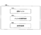
- FIG. 4 is a block diagram illustrating a configuration of a user apparatus according to an embodiment of the present invention.
- the user apparatus 100 includes a transmission buffer 110, a buffer state management unit 120, and a transmission control unit 130.
- the transmission buffer 110 stores uplink data to be transmitted.
- the transmission buffer 110 stores uplink PDCP (Packet Data Convergence Protocol) PDU (Protocol Data Unit). Since each PDCP PDU is assigned a sequence number (PDCP SN), the packet sequence of the PDCP PDU can be reordered based on the sequence number.
- PDCP Packet Data Convergence Protocol
- PDU Protocol Data Unit
- the buffer status management unit 120 manages the amount of data stored in the transmission buffer 110. For example, the buffer status management unit 120 determines the number of bytes of data stored in the transmission buffer 110 and notifies the transmission control unit 130 of the determined number of bytes. In one embodiment, the buffer status management unit 120 monitors the amount of data stored in the transmission buffer 110 and transmits the monitored data amount periodically or in response to occurrence of a predetermined notification event. May be notified. For example, the buffer state management unit 120 may detect the amount of data stored in the transmission buffer 110 in response to an instruction from the transmission control unit 130 and notify the transmission control unit 130 of the detected data amount. .
- the transmission control unit 130 transmits the uplink data stored in the transmission buffer 110 when the threshold for the data amount stored in the transmission buffer 110 and the stored data amount are equal to or less than the threshold.
- split trigger information indicating the base station 200B is received, and uplink data stored in the transmission buffer 110 is transmitted according to whether or not the amount of data stored in the transmission buffer 110 is equal to or less than a threshold value.
- the base station 200A or the base station 200B is selected.
- the split trigger information indicates information for triggering split transmission (bearer split) of uplink data to the master base station 200A and the secondary base station 200B.
- the base station 200 specified by the split trigger information may be a base station 200A or 200B that provides a cell that can be expected to have a higher throughput, or a base station 200A that provides a cell that can stably realize a throughput of a predetermined level or higher. 200B may be sufficient.
- the threshold value may be a data amount that can ensure a throughput of a predetermined level or more using a cell of the designated base station 200, or can be scheduled to the user apparatus 100 in the designated base station 200. The amount of data that can be transmitted using the maximum radio resource may be used.
- the transmission control unit 130 may receive split trigger information from the dual connectivity master base station 200A when bearer splitting or split transmission is set by RRC.
- the transmission control unit 130 when the amount of data stored in the transmission buffer 110 is less than or equal to the threshold, the uplink data stored in the transmission buffer 110 is designated as the base station 200A in the split trigger information. Or, when the amount of data stored in the transmission buffer 110 is larger than the threshold value, the uplink data stored in the transmission buffer 110 is transmitted to the designated base station 200A and the base station 200B. Also good. On the other hand, when the amount of data stored in the transmission buffer 110 is larger than the threshold value, the transmission control unit 130 designates uplink data having a data amount corresponding to the threshold value among the uplink data stored in the transmission buffer 110. The uplink data having a data amount exceeding the threshold may be transmitted to the other base station 200A or 200B.
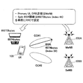
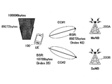
- the transmission control unit 130 receives split trigger information from the master base station 200 ⁇ / b> A, the split trigger information specifies a threshold value of 89272 bytes, and data stored in the transmission buffer 110. While the amount is 89272 bytes or less, it is assumed that the master base station 200A is designated as the base station to which the uplink data stored in the transmission buffer 110 is to be transmitted. In the example of FIG. 5, since the amount of data stored in the transmission buffer 110 is 6074 bytes, which is equal to or less than the specified threshold, the transmission control unit 130 transfers the stored uplink data via CC # 1. Transmit only to the master base station 200A.
- the transmission control unit 130 does not use the secondary base station 200B for uplink data transmission while the stored data amount is equal to or less than the threshold value.
- the transmission control unit 130 may notify the amount of uplink data transmitted to the master base station 200A in order to request a radio resource for transmitting uplink data.
- the transmission control unit 130 may notify the master base station 200A of the amount of uplink data to be transmitted by using BSR (Buffer Status Report).
- BSR Buffer Status Report
- the master base station 200A schedules the user apparatus 100 with radio resources for transmitting 6074-byte uplink data.
- the transmission control unit 130 transmits uplink data to the master base station 200A using the scheduled radio resource.
- the transmission control unit 130 increases the stored 100,000 bytes.
- the transmission control unit 130 notifies the master base station 200A and the secondary base station 200B of the amount of uplink data to be transmitted to the master base station 200A and the secondary base station 200B in order to request radio resources for transmitting uplink data. May be.
- the transmission control unit 130 may notify the master base station 200A and the secondary base station 200B of the amount of uplink data to be transmitted by BSR.
- the master base station 200A schedules radio resources for transmitting 89272 bytes of uplink data to the user apparatus 100, and the secondary base station 200B transmits 10728 bytes of uplink data. Schedule radio resources to the user equipment 100.
- the transmission control unit 130 transmits uplink data to the master base station 200A and the secondary base station 200B using the scheduled radio resource. 5 and 6, the master base station 200A is specified in the split trigger information. However, the present invention is not limited to this, and the secondary base station 200B may be specified. .
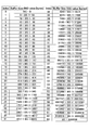
- the transmission control unit 130 has correspondence information indicating an association between each range of the data amount stored in the transmission buffer 110 and an index value indicating the range, and the transmission control unit 130 Split trigger information having a threshold indicated by the index value to be received may be received.
- the transmission control unit 130 may notify the master base station 200A and the secondary base station 200B of the data amount of the uplink data transmitted to the master base station 200A and the secondary base station 200B with the corresponding index values.
- the correspondence information may be configured in a table format as shown in FIG. According to the correspondence information shown in FIG. 7, the threshold value of 89272 bytes in the specific examples of FIGS.
- the transmission control unit 130 may notify the data amount of 6074 bytes transmitted to the main base station 200 ⁇ / b> A by the index 32 in the BSR.
- the transmission control unit 130 notifies the data amount of 89272 bytes transmitted to the main base station 200A by the index 45 in the BSR, and the data amount of 10728 bytes transmitted to the secondary base station 200B. May be notified by the index 35 in the BSR.
- FIG. 8 is a flowchart illustrating uplink data transmission processing in a user apparatus according to an embodiment of the present invention.
- step S101 the user apparatus 100 determines that the threshold for the amount of data stored in the transmission buffer 110 that stores the uplink data to be transmitted and the stored data amount are equal to or less than the threshold.
- split trigger information indicating the base station 200A or 200B that transmits the uplink data stored in the transmission buffer 110 is received.
- the user apparatus 100 may receive split trigger information from the master base station 200A when the bearer split is set by RRC.
- the user apparatus 100 may have correspondence information indicating an association between each range of the data amount stored in the transmission buffer 110 and an index value indicating the range, and the threshold is determined by the index value. May be specified. In the following, it is assumed that the split trigger information designates the master base station 200A without limitation.
- step S102 the user apparatus 100 determines whether the amount of data stored in the transmission buffer 110 is equal to or less than a threshold value. According to the determination result of step S102, the user apparatus 100 selects the base station 200A or the base station 200B that transmits the uplink data stored in the transmission buffer 110 from the base stations 200A and 200B.
- the user apparatus 100 transmits uplink data to the master base station 200A specified in the split trigger information.
- the data amount stored in the transmission buffer 110 exceeds the threshold value (S102: No)
- the user apparatus 100 sets the uplink data having the data amount corresponding to the threshold value in the master base station specified in the split trigger information.
- the uplink data having a data amount exceeding the threshold that is, the remaining uplink data is transmitted to the secondary base station 200B.
- the user apparatus 100 notifies the amount of uplink data transmitted to the master base station 200A and / or the secondary base station 200B by BSR in order to request radio resources for transmitting uplink data. May be. Further, the data amount may be notified by an index value.
Landscapes
- Engineering & Computer Science (AREA)
- Signal Processing (AREA)
- Computer Networks & Wireless Communication (AREA)
- Mobile Radio Communication Systems (AREA)
Priority Applications (4)
| Application Number | Priority Date | Filing Date | Title |
|---|---|---|---|
| US15/125,381 US10524242B2 (en) | 2014-03-18 | 2015-02-26 | User equipment and uplink data transmission method |
| ES15765750T ES2905299T3 (es) | 2014-03-18 | 2015-02-26 | Equipo de usuario y método de transmisión de datos de enlace ascendente |
| EP15765750.3A EP3122114B1 (en) | 2014-03-18 | 2015-02-26 | User equipment and uplink data transmission method |
| CN201580013791.4A CN106105307B (zh) | 2014-03-18 | 2015-02-26 | 用户装置以及上行链路数据发送方法 |
Applications Claiming Priority (2)
| Application Number | Priority Date | Filing Date | Title |
|---|---|---|---|
| JP2014-055169 | 2014-03-18 | ||
| JP2014055169A JP6148635B2 (ja) | 2014-03-18 | 2014-03-18 | ユーザ装置及びアップリンクデータ送信方法 |
Publications (1)
| Publication Number | Publication Date |
|---|---|
| WO2015141425A1 true WO2015141425A1 (ja) | 2015-09-24 |
Family
ID=54144401
Family Applications (1)
| Application Number | Title | Priority Date | Filing Date |
|---|---|---|---|
| PCT/JP2015/055564 WO2015141425A1 (ja) | 2014-03-18 | 2015-02-26 | ユーザ装置及びアップリンクデータ送信方法 |
Country Status (7)
| Country | Link |
|---|---|
| US (1) | US10524242B2 (zh) |
| EP (1) | EP3122114B1 (zh) |
| JP (1) | JP6148635B2 (zh) |
| CN (1) | CN106105307B (zh) |
| CL (1) | CL2016002297A1 (zh) |
| ES (1) | ES2905299T3 (zh) |
| WO (1) | WO2015141425A1 (zh) |
Families Citing this family (13)
| Publication number | Priority date | Publication date | Assignee | Title |
|---|---|---|---|---|
| EP3257317B1 (en) * | 2015-02-13 | 2022-08-03 | Nokia Technologies Oy | Uplink scheduling with wlan/3gpp aggregation |
| WO2017140361A1 (en) * | 2016-02-18 | 2017-08-24 | Nokia Solutions And Networks Oy | Uplink selection for wireless network based on network cell weight and link-specific weight for wireless links |
| EP3461216B1 (en) | 2016-06-30 | 2023-12-13 | Huawei Technologies Co., Ltd. | Multi-connection communication method and device |
| US10320519B1 (en) * | 2017-01-23 | 2019-06-11 | Sprint Spectrum L.P. | Selective discontinuation of carrier aggregation service to facilitate service of other device |
| US11291036B2 (en) * | 2017-03-24 | 2022-03-29 | Qualcomm Incorporated | Scheduling requests and buffer status reports for low latency wireless communications |
| WO2018172542A1 (en) * | 2017-03-24 | 2018-09-27 | Telefonaktiebolaget Lm Ericsson (Publ) | Data buffer handling for dual connectivity |
| CN109309563B (zh) * | 2017-07-27 | 2021-12-24 | 科大国盾量子技术股份有限公司 | 一种信息的纠错处理方法及系统 |
| US10999773B2 (en) * | 2017-08-11 | 2021-05-04 | Gogo Business Aviation Llc | Opportunistic balancing in multiple links |
| WO2020156211A1 (zh) * | 2019-01-31 | 2020-08-06 | 华为技术有限公司 | 数据发送方法及终端设备 |
| CN111510951A (zh) * | 2019-01-31 | 2020-08-07 | 华为技术有限公司 | 数据发送方法及终端设备 |
| EP4066554A4 (en) * | 2019-11-25 | 2023-07-26 | Qualcomm Incorporated | METHOD AND APPARATUS FOR SWITCHING AN UPLINK TRANSMISSION TO A SPLIT UPLINK CARRIER |
| CN112996115B (zh) * | 2019-12-18 | 2023-04-07 | 大唐移动通信设备有限公司 | 一种上行资源分配的方法及装置 |
| US11350313B1 (en) * | 2020-09-03 | 2022-05-31 | Sprint Spectrum L.P. | Dynamic control of uplink communication from a dual-connected device, based on antenna pattern efficiency per connection |
Family Cites Families (3)
| Publication number | Priority date | Publication date | Assignee | Title |
|---|---|---|---|---|
| GB2472789A (en) * | 2009-08-17 | 2011-02-23 | Nec Corp | In a lte-advanced network a target enb sends a source enb information to indicate to the ue which of multiple component carriers is to be used for initail acc |
| US8625415B2 (en) * | 2010-04-02 | 2014-01-07 | Nokia Siemens Networks Oy | Dynamic buffer status report selection for carrier aggregation |
| US9629025B2 (en) * | 2013-05-03 | 2017-04-18 | Blackberry Limited | Controlling data offload in response to feedback information |
-
2014
- 2014-03-18 JP JP2014055169A patent/JP6148635B2/ja active Active
-
2015
- 2015-02-26 US US15/125,381 patent/US10524242B2/en active Active
- 2015-02-26 ES ES15765750T patent/ES2905299T3/es active Active
- 2015-02-26 CN CN201580013791.4A patent/CN106105307B/zh active Active
- 2015-02-26 WO PCT/JP2015/055564 patent/WO2015141425A1/ja active Application Filing
- 2015-02-26 EP EP15765750.3A patent/EP3122114B1/en active Active
-
2016
- 2016-09-13 CL CL2016002297A patent/CL2016002297A1/es unknown
Non-Patent Citations (4)
| Title |
|---|
| 3GPP TS 36.321 V12.0.0, December 2013 (2013-12-01), XP055226571 * |
| ALCATEL -LUCNET SHANGHAI BELL ET AL.: "BSR and SR for dual connectivity", 3GPP R2- 134381, XP050737092 * |
| PANASONIC: "BSR Reporting Options for Dual Connectivity", 3GPP R2-140475, XP050737656 * |
| See also references of EP3122114A4 * |
Also Published As
| Publication number | Publication date |
|---|---|
| CN106105307A (zh) | 2016-11-09 |
| EP3122114A1 (en) | 2017-01-25 |
| CL2016002297A1 (es) | 2017-02-10 |
| JP6148635B2 (ja) | 2017-06-14 |
| US20170079015A1 (en) | 2017-03-16 |
| EP3122114B1 (en) | 2022-01-12 |
| JP2015177530A (ja) | 2015-10-05 |
| CN106105307B (zh) | 2019-09-17 |
| ES2905299T3 (es) | 2022-04-07 |
| US10524242B2 (en) | 2019-12-31 |
| EP3122114A4 (en) | 2017-03-22 |
Similar Documents
| Publication | Publication Date | Title |
|---|---|---|
| JP6148635B2 (ja) | ユーザ装置及びアップリンクデータ送信方法 | |
| JP6425707B2 (ja) | ユーザ装置及びアップリンクデータ送信方法 | |
| US10708940B2 (en) | Method and apparatus for reporting buffer state by user equipment in communication system | |
| JP6166189B2 (ja) | 移動通信システム及び移動局装置 | |
| KR101870851B1 (ko) | 버퍼 상태 보고(bsr)의 트리거 방법 및 장치 | |
| KR20180004257A (ko) | 단말, 기지국 및 스케줄링 요청 송신 방법 | |
| EP3301874B1 (en) | Data transmission method and relevant device | |
| KR20180077270A (ko) | 피드백을 송수신하는 방법 및 장치 | |
| US20200008250A1 (en) | Wireless Connection Establishment Method And Apparatus | |
| WO2015044769A2 (en) | Method and apparatus for scheduling user equipment | |
| JP6510694B2 (ja) | 移動局及び上りリンクデータ量報告方法 | |
| JP6438524B2 (ja) | ユーザ装置及びアップリンクデータ送信方法 | |
| JP2017038335A (ja) | ユーザ装置及び通信方法 | |
| JP5297548B1 (ja) | 移動通信システムにおける基地局及び制御方法 | |
| JP6211845B2 (ja) | 移動局及び移動通信システム | |
| JP2017028415A (ja) | ユーザ装置及び通信方法 | |
| JP6298745B2 (ja) | ユーザ装置及び基地局 | |
| JP2016123051A (ja) | 基地局 | |
| JP2016197820A (ja) | ユーザ装置、及び滞留データ量報告方法 | |
| JP2019068459A (ja) | 基地局 | |
| WO2016172822A1 (zh) | 共享频谱上的数据传输方法、设备和系统 |
Legal Events
| Date | Code | Title | Description |
|---|---|---|---|
| 121 | Ep: the epo has been informed by wipo that ep was designated in this application |
Ref document number: 15765750 Country of ref document: EP Kind code of ref document: A1 |
|
| REEP | Request for entry into the european phase |
Ref document number: 2015765750 Country of ref document: EP |
|
| WWE | Wipo information: entry into national phase |
Ref document number: 2015765750 Country of ref document: EP |
|
| WWE | Wipo information: entry into national phase |
Ref document number: 15125381 Country of ref document: US |
|
| NENP | Non-entry into the national phase |
Ref country code: DE |