EP3122114A1 - User equipment and uplink data transmission method - Google Patents
User equipment and uplink data transmission method Download PDFInfo
- Publication number
- EP3122114A1 EP3122114A1 EP15765750.3A EP15765750A EP3122114A1 EP 3122114 A1 EP3122114 A1 EP 3122114A1 EP 15765750 A EP15765750 A EP 15765750A EP 3122114 A1 EP3122114 A1 EP 3122114A1
- Authority
- EP
- European Patent Office
- Prior art keywords
- base station
- uplink data
- transmission buffer
- transmission
- stored
- Prior art date
- Legal status (The legal status is an assumption and is not a legal conclusion. Google has not performed a legal analysis and makes no representation as to the accuracy of the status listed.)
- Granted
Links
- 230000005540 biological transmission Effects 0.000 title claims abstract description 134
- 238000000034 method Methods 0.000 title claims abstract description 12
- 230000009977 dual effect Effects 0.000 claims abstract description 21
- 238000004891 communication Methods 0.000 description 17
- 239000000969 carrier Substances 0.000 description 9
- 230000002776 aggregation Effects 0.000 description 7
- 238000004220 aggregation Methods 0.000 description 7
- 230000006870 function Effects 0.000 description 7
- 238000010586 diagram Methods 0.000 description 2
- 230000004044 response Effects 0.000 description 2
- 230000008901 benefit Effects 0.000 description 1
- 238000012217 deletion Methods 0.000 description 1
- 230000037430 deletion Effects 0.000 description 1
- 230000010365 information processing Effects 0.000 description 1
- 230000007774 longterm Effects 0.000 description 1
- 238000012986 modification Methods 0.000 description 1
- 230000004048 modification Effects 0.000 description 1
- 230000000737 periodic effect Effects 0.000 description 1
- 238000012545 processing Methods 0.000 description 1
Images


Classifications
-
- H—ELECTRICITY
- H04—ELECTRIC COMMUNICATION TECHNIQUE
- H04L—TRANSMISSION OF DIGITAL INFORMATION, e.g. TELEGRAPHIC COMMUNICATION
- H04L47/00—Traffic control in data switching networks
- H04L47/10—Flow control; Congestion control
- H04L47/30—Flow control; Congestion control in combination with information about buffer occupancy at either end or at transit nodes
-
- H—ELECTRICITY
- H04—ELECTRIC COMMUNICATION TECHNIQUE
- H04W—WIRELESS COMMUNICATION NETWORKS
- H04W72/00—Local resource management
- H04W72/20—Control channels or signalling for resource management
- H04W72/23—Control channels or signalling for resource management in the downlink direction of a wireless link, i.e. towards a terminal
-
- H—ELECTRICITY
- H04—ELECTRIC COMMUNICATION TECHNIQUE
- H04L—TRANSMISSION OF DIGITAL INFORMATION, e.g. TELEGRAPHIC COMMUNICATION
- H04L5/00—Arrangements affording multiple use of the transmission path
- H04L5/0001—Arrangements for dividing the transmission path
- H04L5/0003—Two-dimensional division
- H04L5/0005—Time-frequency
- H04L5/0007—Time-frequency the frequencies being orthogonal, e.g. OFDM(A), DMT
- H04L5/001—Time-frequency the frequencies being orthogonal, e.g. OFDM(A), DMT the frequencies being arranged in component carriers
-
- H—ELECTRICITY
- H04—ELECTRIC COMMUNICATION TECHNIQUE
- H04L—TRANSMISSION OF DIGITAL INFORMATION, e.g. TELEGRAPHIC COMMUNICATION
- H04L5/00—Arrangements affording multiple use of the transmission path
- H04L5/003—Arrangements for allocating sub-channels of the transmission path
- H04L5/0032—Distributed allocation, i.e. involving a plurality of allocating devices, each making partial allocation
-
- H—ELECTRICITY
- H04—ELECTRIC COMMUNICATION TECHNIQUE
- H04L—TRANSMISSION OF DIGITAL INFORMATION, e.g. TELEGRAPHIC COMMUNICATION
- H04L5/00—Arrangements affording multiple use of the transmission path
- H04L5/003—Arrangements for allocating sub-channels of the transmission path
- H04L5/0058—Allocation criteria
-
- H—ELECTRICITY
- H04—ELECTRIC COMMUNICATION TECHNIQUE
- H04W—WIRELESS COMMUNICATION NETWORKS
- H04W28/00—Network traffic management; Network resource management
- H04W28/02—Traffic management, e.g. flow control or congestion control
- H04W28/0231—Traffic management, e.g. flow control or congestion control based on communication conditions
- H04W28/0236—Traffic management, e.g. flow control or congestion control based on communication conditions radio quality, e.g. interference, losses or delay
-
- H—ELECTRICITY
- H04—ELECTRIC COMMUNICATION TECHNIQUE
- H04W—WIRELESS COMMUNICATION NETWORKS
- H04W28/00—Network traffic management; Network resource management
- H04W28/02—Traffic management, e.g. flow control or congestion control
- H04W28/0278—Traffic management, e.g. flow control or congestion control using buffer status reports
-
- H—ELECTRICITY
- H04—ELECTRIC COMMUNICATION TECHNIQUE
- H04W—WIRELESS COMMUNICATION NETWORKS
- H04W28/00—Network traffic management; Network resource management
- H04W28/02—Traffic management, e.g. flow control or congestion control
- H04W28/10—Flow control between communication endpoints
- H04W28/14—Flow control between communication endpoints using intermediate storage
-
- H—ELECTRICITY
- H04—ELECTRIC COMMUNICATION TECHNIQUE
- H04W—WIRELESS COMMUNICATION NETWORKS
- H04W72/00—Local resource management
- H04W72/20—Control channels or signalling for resource management
- H04W72/21—Control channels or signalling for resource management in the uplink direction of a wireless link, i.e. towards the network
-
- H—ELECTRICITY
- H04—ELECTRIC COMMUNICATION TECHNIQUE
- H04W—WIRELESS COMMUNICATION NETWORKS
- H04W76/00—Connection management
- H04W76/10—Connection setup
- H04W76/15—Setup of multiple wireless link connections
-
- H—ELECTRICITY
- H04—ELECTRIC COMMUNICATION TECHNIQUE
- H04L—TRANSMISSION OF DIGITAL INFORMATION, e.g. TELEGRAPHIC COMMUNICATION
- H04L5/00—Arrangements affording multiple use of the transmission path
- H04L5/003—Arrangements for allocating sub-channels of the transmission path
- H04L5/0044—Arrangements for allocating sub-channels of the transmission path allocation of payload
Definitions
- the present invention relates to a radio communication system.
- LTE-Advanced Long Term Evolution
- 3GPP 3 rd Generation Partnership Project
- CA carrier aggregation
- CC component carrier having the maximum bandwidth of 20 MHz supported by the LTE systems is used as a basic component, and it is designed to achieve communication in a broader band by using these multiple component carriers simultaneously.
- UE user equipment
- eNB evolved NodeB
- PCell primary cell
- SCell secondary cell
- the primary cell is similar to a serving cell in the LTE systems and serves as a cell to ensure connectivity between the user equipment and a network.
- the secondary cell is a cell configured for the user equipment additionally to the primary cell. Addition and deletion of the secondary cell are performed with an RRC (Radio Resource Control) configuration.
- RRC Radio Resource Control
- Rel-10 In the carrier aggregation up to LTE Release 10 (Rel-10), as illustrated in the left side in FIG. 1 , it is defined that user equipment uses multiple component carriers served from a single base station to conduct simultaneous communication. Meanwhile, in Rel-12, the carrier aggregation in Rel-10 is further extended, and as illustrated in the right side in FIG. 1 , dual connectivity where the user equipment uses multiple component carriers served from multiple base stations to conduct the simultaneous communication is discussed. For example, if all component carriers cannot be accommodated in a single base station, it is considered that the dual connectivity can be effectively utilized to achieve a throughput nearly equal to that in Rel-10.
- bearer splitting where user equipment (UE) splits a single EPS (Evolved Packet System) bearer or packet sequence in a predefined manner and uses component carriers served from multiple base stations (eNB#1, eNB#2) to transmit the respective split packet sequences simultaneously is discussed.
- EPS Evolved Packet System
- the base station eNB#2 serving as a non-anchor node Upon receiving the split packet sequence via CC#2, the base station eNB#2 serving as a non-anchor node forwards the received packet sequence to the anchor base station eNB#1.
- eNB#1 Upon receiving the packet sequence forwarded from eNB#2, eNB#1 reorders the packet sequence received via CC#1 and the packet sequence received from eNB#2 to reconstruct the packet sequence from the user equipment and forwards the reconstructed packet sequence to a core node (CN).
- CN core node
- the data amount ratio is not properly set in accordance with the proposed semi-static data amount ratio setting method, there is a likelihood that an uplink throughput cannot be improved. For example, if a throughput sufficient to transmit distributed data cannot be implemented in a certain cell due to degraded communication quality, the data distributed to the cell would be accumulated in a transmission buffer for storing to-be-transmitted uplink data.
- one object of the present invention is to provide techniques for transmitting uplink data in the dual connectivity efficiently.
- one aspect of the present invention relates to user equipment having a dual connectivity function to communicate with multiple base stations simultaneously, comprising: a transmission buffer configured to store uplink data for transmission; a buffer status management unit configured to manage a data amount stored in the transmission buffer; and a transmission control unit configured to receive splitting trigger information indicative of a threshold for the data amount stored in the transmission buffer and a first base station to transmit the uplink data stored in the transmission buffer when the stored data amount is smaller than or equal to the threshold and select a base station to transmit the uplink data stored in the transmission buffer from the multiple base stations depending on whether the data amount stored in the transmission buffer is smaller than or equal to the threshold.
- Another aspect of the present invention relates to an uplink data transmission method for use in user equipment having a dual connectivity function to communicate with multiple base stations simultaneously, the method comprising: receiving splitting trigger information indicative of a threshold for a data amount stored in a transmission buffer for storing uplink data for transmission and a first base station to transmit the uplink data stored in the transmission buffer when the stored data amount is smaller than or equal to the threshold; determining whether the data amount stored in the transmission buffer is smaller than or equal to the threshold; selecting a base station to transmit the uplink data stored in the transmission buffer from the multiple base stations depending on a result of the determination; and transmitting the uplink data to the selected base station.
- the user equipment having a dual connectivity function to communicate with multiple base stations simultaneously.
- the user equipment receives splitting trigger information for triggering splitting transmission (bearer splitting) of uplink data to multiple base stations from a master base station.
- the splitting trigger information indicates a threshold for a data amount stored in a transmission buffer for storing to-be-transmitted uplink data and a base station to transmit the uplink data stored in the transmission buffer when the stored data amount is smaller than or equal to the threshold.
- the user equipment selects the base station to transmit the uplink data stored in the transmission buffer from the multiple base stations depending on whether the data amount stored in the transmission buffer is smaller than or equal to the threshold.
- the user equipment when the data amount stored in the transmission buffer is smaller than or equal to the threshold, transmits the uplink data stored in the transmission buffer to the base station indicated in the splitting trigger information, and otherwise if the data amount stored in the transmission buffer is larger than the threshold, the user equipment transmits an amount of uplink data corresponding to the threshold in the uplink data stored in the transmission buffer to the indicated base station and an amount of uplink data exceeding the threshold to another base station.
- FIG. 3 is a schematic view for illustrating a radio communication system according to one embodiment of the present invention.
- a radio communication system 10 has user equipment 100 and base stations 200A, 200B.
- the radio communication system 10 supports dual connectivity where the user equipment 100 uses component carriers CC#1, CC#2 served from the multiple base stations 200A, 200B to conduct simultaneous communication, and as illustrated, the user equipment 100 uses a dual connectivity function to communicate with the master base station (MeNB) 200A and the secondary base station (SeNB) 200B.
- MeNB master base station
- SeNB secondary base station
- the user equipment 100 has the dual connectivity function to communicate with the multiple base stations 200A, 200B simultaneously.
- the user equipment 100 may be any appropriate information processing device with a radio communication function such as a smartphone, a mobile phone, a tablet and a mobile router.
- the user equipment 100 is arranged from a CPU (Central Processing Unit) such as a processor, a memory device such as a RAM (Random Access Memory) and a flash memory, a radio communication device for transmitting and receiving radio signals to/from the base stations 200A, 200B and so on.
- functions and operations of the user equipment 100 as stated below may be implemented by the CPU running data and programs stored in the memory device.
- the user equipment 100 is not limited to the above-stated hardware configuration and may be arranged from circuits for implementing one or more of operations as stated below.
- the base stations 200A, 200B (which may be collectively referred to as the base stations 200 hereinafter) establish a radio connection to the user equipment 100 to transmit downlink (DL) packets received from network devices, such as an upper station and a server, communicatively connected on a core network (not shown) to the user equipment 100 as well as transmit uplink (UL) packets received from the user equipment 100 to the network devices.
- the base station 200A serves as a master base station (MeNB) or a primary base station
- the base station 200B serves as a secondary base station (SeNB).
- the master base station 200A controls simultaneous communication between the user equipment 100 and the base stations 200A, 200B in accordance with the dual connectivity and controls communication with the upper core network (not shown).
- the master base station 200A configures the secondary cell CC#2 served from the secondary base station 200B for the user equipment 100 and forwards uplink data received via the primary cell CC#1 and the secondary cell CC#2 to the core network.
- the user equipment 100 splits the uplink data into two packet sequences in accordance with a predefined splitting manner and transmits the respective split packet sequences to the master base station 200A and the secondary base station 200B via CC#1 and CC#2, respectively.
- the secondary base station 200B Upon receiving the split packet sequence from the user equipment 100, the secondary base station 200B forwards the received packet sequence to the master base station 200A.
- the master base station 200A Upon receiving the forwarded packet sequence, the master base station 200A reorders the packets received from the secondary base station 200B and the packets received from the user equipment 100 via CC#1 to reconstruct the packet sequence and forwards the reconstructed packet sequence to the core network.
- FIG. 4 is a block diagram for illustrating an arrangement of the user equipment according to one embodiment of the present invention.
- the user equipment 100 has a transmission buffer 110, a buffer status management unit 120 and a transmission control unit 130.
- the transmission buffer 110 stores uplink data for transmission.
- the transmission buffer 110 stores uplink PDCP (Packet Data Convergence Protocol) PDUs (Protocol Data Units). Since sequence numbers (PDCP SNs) are assigned to the respective PDCP PDUs, a packet sequence of the PDCP PDUs can be reordered based on the sequence numbers.
- PDCP Packet Data Convergence Protocol
- sequence numbers PDCP SNs
- the buffer status management unit 120 manages a data amount stored in the transmission buffer 110. For example, the buffer status management unit 120 determines the number of bytes of data stored in the transmission buffer 110 and indicates the determined number of bytes to the transmission control unit 130. In one embodiment, the buffer status management unit 120 may monitor the data amount stored in the transmission buffer 110 and indicate the monitored data amount to the transmission control unit 130 in a periodic manner or in response to occurrence of a predefined indication event. For example, in response to an instruction from the transmission control unit 130, the buffer status management unit 120 may detect the data amount stored in the transmission buffer 110 and indicate the detected data amount to the transmission control unit 130.
- the transmission control unit 130 receives splitting trigger information indicative of a threshold for the data amount stored in the transmission buffer 110 and the base station 200A or the base station 200B to transmit the uplink data stored in the transmission buffer 110 when the stored data amount is smaller than or equal to the threshold and select the base station 200A or the base station 200B to transmit the uplink data stored in the transmission buffer 110 depending on whether the data amount stored in the transmission buffer 110 is smaller than or equal to the threshold.
- the splitting trigger information indicates information for triggering splitting transmission (bearer splitting) of uplink data to the master base station 200A and the secondary base station 200B.
- the base station 200 indicated in the splitting trigger information may be the base station 200A or 200B serving a cell expected to achieve a higher throughput or the base station 200A or the base station 200B serving a cell that can stably achieve a throughput higher than or equal to a predetermined level.
- the threshold may be a data amount for which the throughput higher than or equal to the predetermined level can be ensured by using a cell of the indicated base station 200.
- the threshold may be a data amount that can be transmitted by using the maximum radio resources at the indicated base station 200 allowed to be scheduled for the user equipment 100.
- the present invention is not limited to it, and the base station and/or the threshold selected in accordance with any appropriate criteria may be used.
- the transmission control unit 130 may receive the splitting trigger information from the master base station 200A for dual connectivity.
- the transmission control unit 130 may transmit the uplink data stored in the transmission buffer 110 to the base station 200A or the base station 200B indicated in the splitting trigger information, and when the data amount stored in the transmission buffer 110 is larger than the threshold, the transmission control unit 130 may transmit the uplink data stored in the transmission buffer 110 to the indicated base stations 200A and 200B.
- the transmission control unit 130 may transmit an amount of uplink data corresponding to the threshold in the uplink data stored in the transmission buffer 110 to the indicated base station 200A or 200B and an amount of uplink data exceeding the threshold to the other base station 200A or 200B.
- the transmission control unit 130 receives the splitting trigger information from the master base station 200A, and the splitting trigger information indicates 89272 bytes as the threshold and the master base station 200A as the base station to transmit the uplink data stored in the transmission buffer 110 during the data amount stored in the transmission buffer 110 being smaller than or equal to 89272 bytes, for example.
- the data amount stored in the transmission buffer 110 is 6074 bytes, which is below the indicated threshold, and the transmission control unit 130 accordingly transmits the stored uplink data only to the master base station 200A via CC#1.
- the transmission control unit 130 may indicate the amount of uplink data for transmission to the master base station 200A to request radio resources to transmit the uplink data.
- the transmission control unit 130 may indicate the amount of uplink data for transmission to the master base station 200A in a BSR (Buffer Status Report).
- BSR Buffer Status Report
- the master base station 200A schedules radio resources to transmit 6074 bytes of uplink data for the user equipment 100.
- the transmission control unit 130 uses the scheduled radio resources to transmit the uplink data to the master base station 200A.
- the transmission control unit 130 starts to transmit the uplink data to the secondary base station 200B.
- the transmission control unit 130 may indicate respective data amounts of uplink data for transmission to the master base station 200A and the secondary base station 200B to request radio resources to transmit the uplink data.
- the transmission control unit 130 may indicate the data amounts of uplink data for transmission to the master base station 200A and the secondary base station 200B in a BSR.
- the master base station 200A schedules radio resources to transmit the 89272 bytes of uplink data for the user equipment 100
- the secondary base station 200B schedules radio resources to transmit the 10728 bytes of uplink data for the user equipment 100.
- the transmission control unit 130 uses the scheduled radio resources to transmit the uplink data to the master base station 200A and the secondary base station 200B.
- the master base station 200A is indicated in the splitting trigger information, but the present invention is not limited to it.
- the secondary base station 200B may be indicated.
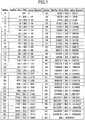
- the transmission control unit 130 may have correspondence information indicative of association of respective ranges of data amounts stored in the transmission buffer 110 with index values representing the respective ranges, and the transmission control unit 130 may receive the splitting trigger information including the threshold indicated by the corresponding index value. Similarly, the transmission control unit 130 may indicate the respective data amounts of uplink data transmitted to the master base station 200A and the secondary base station 200B by the corresponding index values to the master base station 200A and the secondary base station 200B.
- the correspondence information may be arranged in a table form as illustrated in FIG. 7 . According to the correspondence information as illustrated in FIG. 7 , the threshold of 89272 bytes in the examples in FIGS.
- the master base station 200A may indicate the threshold by index 45 in the splitting trigger information.
- the transmission control unit 130 may indicate the data amount of 6074 bytes transmitted to the master base station 200A by index 32 in a BSR.
- the transmission control unit 130 may indicate the data amount of 89272 bytes transmitted to the master base station 200A by index 45 in the BSR and the data amount of 10728 bytes transmitted to the secondary base station 200B by index 35 in the BSR.
- the representation of data amounts with the indices can indicate the data amounts with a few number of bits compared to the bit representation of the data amounts.
- FIG. 8 is a flowchart for illustrating an uplink data transmission operation in the user equipment according to one embodiment of the present invention.
- the user equipment 100 receives splitting trigger information indicative of a threshold for a data amount stored in the transmission buffer 110 for storing uplink data for transmission and the base station 200A or 200B to transmit the uplink data stored in the transmission buffer 110 when the stored data amount is smaller than or equal to the threshold.
- the user equipment 100 may receive the splitting trigger information from the master base station 200A.
- the user equipment 100 may have correspondence information indicative of respective ranges of data amounts stored in the transmission buffer 110 with index values representing the respective ranges in advance, and the threshold may be indicated by the index value. It is assumed below that the splitting trigger information, but is not limited to it, indicates the master base station 200A.
- the user equipment 100 determines whether the data amount stored in the transmission buffer 110 is smaller than or equal to the threshold.
- the user equipment 100 selects the base station 200A or the base station 200B to transmit the uplink data stored in the transmission buffer 110 from the base stations 200A and 200B depending on the determination result at step S102.
- the user equipment 100 transmits the uplink data to the master base station 200A indicated in the splitting trigger information.
- the user equipment 100 transmits an amount of uplink data corresponding to the threshold to the master base station 200A indicated in the splitting trigger information and an amount of uplink data exceeding the threshold, that is, the remaining amount of uplink data, to the secondary base station 200B.
- the user equipment 100 may indicate data amounts of uplink data for transmission to the master base station 200A and/or the secondary base station 200B in a BSR to request radio resources to transmit the uplink data. Also, the data amounts may be indicated by the index values.
Abstract
Description
- The present invention relates to a radio communication system.
- Presently, as next-generation communication standards of LTE (Long Term Evolution), 3GPP (3rd Generation Partnership Project) is developing specifications designed to sophisticate LTE-Advanced. In LTE-Advanced systems, carrier aggregation (CA) technique is introduced to achieve a higher throughput than that of LTE systems while ensuring backward compatibility with the LTE systems. In the carrier aggregation, a component carrier (CC) having the maximum bandwidth of 20 MHz supported by the LTE systems is used as a basic component, and it is designed to achieve communication in a broader band by using these multiple component carriers simultaneously.
- In the carrier aggregation, user equipment (UE) can use multiple component carriers simultaneously to communicate with a base station (evolved NodeB: eNB). In the carrier aggregation, a highly reliable primary cell (PCell) to ensure connectivity to the user equipment and a secondary cell (SCell) additionally configured for the user equipment in connection with the primary cell are configured.
- The primary cell is similar to a serving cell in the LTE systems and serves as a cell to ensure connectivity between the user equipment and a network. On the other hand, the secondary cell is a cell configured for the user equipment additionally to the primary cell. Addition and deletion of the secondary cell are performed with an RRC (Radio Resource Control) configuration.
- In the carrier aggregation up to LTE Release 10 (Rel-10), as illustrated in the left side in
FIG. 1 , it is defined that user equipment uses multiple component carriers served from a single base station to conduct simultaneous communication. Meanwhile, in Rel-12, the carrier aggregation in Rel-10 is further extended, and as illustrated in the right side inFIG. 1 , dual connectivity where the user equipment uses multiple component carriers served from multiple base stations to conduct the simultaneous communication is discussed. For example, if all component carriers cannot be accommodated in a single base station, it is considered that the dual connectivity can be effectively utilized to achieve a throughput nearly equal to that in Rel-10. - In the dual connectivity, as illustrated in
FIG. 2 , bearer splitting where user equipment (UE) splits a single EPS (Evolved Packet System) bearer or packet sequence in a predefined manner and uses component carriers served from multiple base stations (eNB#1, eNB#2) to transmit the respective split packet sequences simultaneously is discussed. Specifically, as illustrated, the user equipment splits the to-be-transmitted EPS bearer into packet sequences destined for eNB#1 and eNB#2 in a certain ratio (eNB#1 :eNB# 2 = 4:3 in the illustrated example) and transmits the respective split packet sequences to the base stations eNB#1 and eNB#2 via componentcarriers CC# 1 andCC# 2, respectively. Upon receiving the split packet sequence viaCC# 2, the base station eNB#2 serving as a non-anchor node forwards the received packet sequence to the anchor base station eNB#1. Upon receiving the packet sequence forwarded from eNB#2, eNB#1 reorders the packet sequence received viaCC# 1 and the packet sequence received from eNB#2 to reconstruct the packet sequence from the user equipment and forwards the reconstructed packet sequence to a core node (CN). - See 3GPP TR36.842 "Study on Small Cell enhancements for E-UTRA and E-UTRAN; Higher Layer aspects" for detail, for example.
- For a packet distribution manner to implement the bearer splitting of uplink data, a method for setting a ratio for distributing data amounts of the uplink data over respective component carriers or component groups (CGs) (eNB#1 :
eNB# 2=4:3 in the example inFIG. 2 ) in a semi-static manner has been proposed. - However, if the data amount ratio is not properly set in accordance with the proposed semi-static data amount ratio setting method, there is a likelihood that an uplink throughput cannot be improved. For example, if a throughput sufficient to transmit distributed data cannot be implemented in a certain cell due to degraded communication quality, the data distributed to the cell would be accumulated in a transmission buffer for storing to-be-transmitted uplink data.
- In light of the above problem, one object of the present invention is to provide techniques for transmitting uplink data in the dual connectivity efficiently.
- In order to achieve the above object, one aspect of the present invention relates to user equipment having a dual connectivity function to communicate with multiple base stations simultaneously, comprising: a transmission buffer configured to store uplink data for transmission; a buffer status management unit configured to manage a data amount stored in the transmission buffer; and a transmission control unit configured to receive splitting trigger information indicative of a threshold for the data amount stored in the transmission buffer and a first base station to transmit the uplink data stored in the transmission buffer when the stored data amount is smaller than or equal to the threshold and select a base station to transmit the uplink data stored in the transmission buffer from the multiple base stations depending on whether the data amount stored in the transmission buffer is smaller than or equal to the threshold.
- Another aspect of the present invention relates to an uplink data transmission method for use in user equipment having a dual connectivity function to communicate with multiple base stations simultaneously, the method comprising: receiving splitting trigger information indicative of a threshold for a data amount stored in a transmission buffer for storing uplink data for transmission and a first base station to transmit the uplink data stored in the transmission buffer when the stored data amount is smaller than or equal to the threshold; determining whether the data amount stored in the transmission buffer is smaller than or equal to the threshold; selecting a base station to transmit the uplink data stored in the transmission buffer from the multiple base stations depending on a result of the determination; and
transmitting the uplink data to the selected base station. - According to the present invention, techniques for transmitting uplink data in the dual connectivity efficiently can be provided.
-
-
FIG. 1 is a schematic view for illustrating carrier aggregation; -
FIG. 2 is a schematic view for illustrating bearer splitting in dual connectivity; -
FIG. 3 is a schematic view for illustrating a radio communication system according to one embodiment of the present invention; -
FIG. 4 is a block diagram for illustrating an arrangement of user equipment according to one embodiment of the present invention; -
FIG. 5 is a schematic view for illustrating an uplink data transmission operation according to one embodiment of the present invention; -
FIG. 6 is a schematic view for illustrating an uplink data transmission operation according to one embodiment of the present invention; -
FIG. 7 illustrates a table representing index values indicative of buffer size levels according to one embodiment of the present invention; and -
FIG. 8 is a flowchart for illustrating an uplink data transmission operation according to one embodiment of the present invention. - Embodiments of the present invention are described below with reference to the drawings.
- User equipment having a dual connectivity function to communicate with multiple base stations simultaneously is disclosed. The user equipment receives splitting trigger information for triggering splitting transmission (bearer splitting) of uplink data to multiple base stations from a master base station. The splitting trigger information indicates a threshold for a data amount stored in a transmission buffer for storing to-be-transmitted uplink data and a base station to transmit the uplink data stored in the transmission buffer when the stored data amount is smaller than or equal to the threshold. The user equipment selects the base station to transmit the uplink data stored in the transmission buffer from the multiple base stations depending on whether the data amount stored in the transmission buffer is smaller than or equal to the threshold.
- In one embodiment, when the data amount stored in the transmission buffer is smaller than or equal to the threshold, the user equipment transmits the uplink data stored in the transmission buffer to the base station indicated in the splitting trigger information, and otherwise if the data amount stored in the transmission buffer is larger than the threshold, the user equipment transmits an amount of uplink data corresponding to the threshold in the uplink data stored in the transmission buffer to the indicated base station and an amount of uplink data exceeding the threshold to another base station.
- In this manner, compared to the method for setting the ratio of distributing the to-be-transmitted packets over multiple base stations in a semi-static manner, it can be expected that uplink throughput is improved by setting the threshold and the indicated base station in the splitting trigger information properly, for example.
- A radio communication system according to one embodiment of the present invention is described with reference to
FIG. 3. FIG. 3 is a schematic view for illustrating a radio communication system according to one embodiment of the present invention. - As illustrated in
FIG. 3 , aradio communication system 10 hasuser equipment 100 andbase stations radio communication system 10 supports dual connectivity where theuser equipment 100 uses component carriers CC#1,CC# 2 served from themultiple base stations user equipment 100 uses a dual connectivity function to communicate with the master base station (MeNB) 200A and the secondary base station (SeNB) 200B. - The
user equipment 100 has the dual connectivity function to communicate with themultiple base stations user equipment 100 may be any appropriate information processing device with a radio communication function such as a smartphone, a mobile phone, a tablet and a mobile router. Theuser equipment 100 is arranged from a CPU (Central Processing Unit) such as a processor, a memory device such as a RAM (Random Access Memory) and a flash memory, a radio communication device for transmitting and receiving radio signals to/from thebase stations user equipment 100 as stated below may be implemented by the CPU running data and programs stored in the memory device. However, theuser equipment 100 is not limited to the above-stated hardware configuration and may be arranged from circuits for implementing one or more of operations as stated below. - The
base stations user equipment 100 to transmit downlink (DL) packets received from network devices, such as an upper station and a server, communicatively connected on a core network (not shown) to theuser equipment 100 as well as transmit uplink (UL) packets received from theuser equipment 100 to the network devices. In the illustrated embodiment, thebase station 200A serves as a master base station (MeNB) or a primary base station, and thebase station 200B serves as a secondary base station (SeNB). In the dual connectivity, themaster base station 200A controls simultaneous communication between theuser equipment 100 and thebase stations - In the dual connectivity, the
master base station 200A configures the secondarycell CC# 2 served from thesecondary base station 200B for theuser equipment 100 and forwards uplink data received via the primarycell CC# 1 and the secondarycell CC# 2 to the core network. Specifically, theuser equipment 100 splits the uplink data into two packet sequences in accordance with a predefined splitting manner and transmits the respective split packet sequences to themaster base station 200A and thesecondary base station 200B viaCC# 1 andCC# 2, respectively. Upon receiving the split packet sequence from theuser equipment 100, thesecondary base station 200B forwards the received packet sequence to themaster base station 200A. Upon receiving the forwarded packet sequence, themaster base station 200A reorders the packets received from thesecondary base station 200B and the packets received from theuser equipment 100 viaCC# 1 to reconstruct the packet sequence and forwards the reconstructed packet sequence to the core network. - Next, the user equipment according to one embodiment of the present invention is described with reference to
FIG. 4. FIG. 4 is a block diagram for illustrating an arrangement of the user equipment according to one embodiment of the present invention. - As illustrated in
FIG. 4 , theuser equipment 100 has atransmission buffer 110, a bufferstatus management unit 120 and atransmission control unit 130. - The
transmission buffer 110 stores uplink data for transmission. In one embodiment, thetransmission buffer 110 stores uplink PDCP (Packet Data Convergence Protocol) PDUs (Protocol Data Units). Since sequence numbers (PDCP SNs) are assigned to the respective PDCP PDUs, a packet sequence of the PDCP PDUs can be reordered based on the sequence numbers. - The buffer
status management unit 120 manages a data amount stored in thetransmission buffer 110. For example, the bufferstatus management unit 120 determines the number of bytes of data stored in thetransmission buffer 110 and indicates the determined number of bytes to thetransmission control unit 130. In one embodiment, the bufferstatus management unit 120 may monitor the data amount stored in thetransmission buffer 110 and indicate the monitored data amount to thetransmission control unit 130 in a periodic manner or in response to occurrence of a predefined indication event. For example, in response to an instruction from thetransmission control unit 130, the bufferstatus management unit 120 may detect the data amount stored in thetransmission buffer 110 and indicate the detected data amount to thetransmission control unit 130. - The
transmission control unit 130 receives splitting trigger information indicative of a threshold for the data amount stored in thetransmission buffer 110 and thebase station 200A or thebase station 200B to transmit the uplink data stored in thetransmission buffer 110 when the stored data amount is smaller than or equal to the threshold and select thebase station 200A or thebase station 200B to transmit the uplink data stored in thetransmission buffer 110 depending on whether the data amount stored in thetransmission buffer 110 is smaller than or equal to the threshold. - Here, the splitting trigger information indicates information for triggering splitting transmission (bearer splitting) of uplink data to the
master base station 200A and thesecondary base station 200B. For example, the base station 200 indicated in the splitting trigger information may be thebase station base station 200A or thebase station 200B serving a cell that can stably achieve a throughput higher than or equal to a predetermined level. Also, the threshold may be a data amount for which the throughput higher than or equal to the predetermined level can be ensured by using a cell of the indicated base station 200. Alternatively, the threshold may be a data amount that can be transmitted by using the maximum radio resources at the indicated base station 200 allowed to be scheduled for theuser equipment 100. However, the present invention is not limited to it, and the base station and/or the threshold selected in accordance with any appropriate criteria may be used. In one embodiment, when the bearer splitting or the splitting transmission is configured in an RRC, thetransmission control unit 130 may receive the splitting trigger information from themaster base station 200A for dual connectivity. - In one embodiment, when the data amount stored in the
transmission buffer 110 is smaller than or equal to the threshold, thetransmission control unit 130 may transmit the uplink data stored in thetransmission buffer 110 to thebase station 200A or thebase station 200B indicated in the splitting trigger information, and when the data amount stored in thetransmission buffer 110 is larger than the threshold, thetransmission control unit 130 may transmit the uplink data stored in thetransmission buffer 110 to the indicatedbase stations transmission buffer 110 is larger than the threshold, thetransmission control unit 130 may transmit an amount of uplink data corresponding to the threshold in the uplink data stored in thetransmission buffer 110 to the indicatedbase station other base station - As illustrated in
FIG. 5 , it is assumed that thetransmission control unit 130 receives the splitting trigger information from themaster base station 200A, and the splitting trigger information indicates 89272 bytes as the threshold and themaster base station 200A as the base station to transmit the uplink data stored in thetransmission buffer 110 during the data amount stored in thetransmission buffer 110 being smaller than or equal to 89272 bytes, for example. In the example as illustrated inFIG. 5 , the data amount stored in thetransmission buffer 110 is 6074 bytes, which is below the indicated threshold, and thetransmission control unit 130 accordingly transmits the stored uplink data only to themaster base station 200A viaCC# 1. In other words, while the stored data amount is smaller than or equal to the threshold, thetransmission control unit 130 does not use thesecondary base station 200B for transmission of the uplink data. In one embodiment, thetransmission control unit 130 may indicate the amount of uplink data for transmission to themaster base station 200A to request radio resources to transmit the uplink data. For example, thetransmission control unit 130 may indicate the amount of uplink data for transmission to themaster base station 200A in a BSR (Buffer Status Report). Upon receiving the indication, themaster base station 200A schedules radio resources to transmit 6074 bytes of uplink data for theuser equipment 100. Thetransmission control unit 130 uses the scheduled radio resources to transmit the uplink data to themaster base station 200A. - As illustrated in the example in
FIG. 6 , on the other hand, when the data amount stored in thetransmission buffer 110 reaches 100000 bytes and exceeds the indicated threshold, thetransmission control unit 130 transmits 89272 bytes of uplink data corresponding to the threshold in the stored 100000 bytes of uplink data to themaster base station 200A viaCC# 1 and 10728 bytes (= 100000 bytes - 89272 bytes) of uplink data exceeding the threshold to thesecondary base station 200B viaCC# 2. In other words, upon the stored data amount exceeding the threshold, thetransmission control unit 130 starts to transmit the uplink data to thesecondary base station 200B. In one embodiment, thetransmission control unit 130 may indicate respective data amounts of uplink data for transmission to themaster base station 200A and thesecondary base station 200B to request radio resources to transmit the uplink data. For example, thetransmission control unit 130 may indicate the data amounts of uplink data for transmission to themaster base station 200A and thesecondary base station 200B in a BSR. Upon receiving the indication, themaster base station 200A schedules radio resources to transmit the 89272 bytes of uplink data for theuser equipment 100, and thesecondary base station 200B schedules radio resources to transmit the 10728 bytes of uplink data for theuser equipment 100. Thetransmission control unit 130 uses the scheduled radio resources to transmit the uplink data to themaster base station 200A and thesecondary base station 200B. In the embodiment as illustrated inFIGS. 5 and6 , themaster base station 200A is indicated in the splitting trigger information, but the present invention is not limited to it. Thesecondary base station 200B may be indicated. - In one embodiment, the
transmission control unit 130 may have correspondence information indicative of association of respective ranges of data amounts stored in thetransmission buffer 110 with index values representing the respective ranges, and thetransmission control unit 130 may receive the splitting trigger information including the threshold indicated by the corresponding index value. Similarly, thetransmission control unit 130 may indicate the respective data amounts of uplink data transmitted to themaster base station 200A and thesecondary base station 200B by the corresponding index values to themaster base station 200A and thesecondary base station 200B. For example, the correspondence information may be arranged in a table form as illustrated inFIG. 7 . According to the correspondence information as illustrated inFIG. 7 , the threshold of 89272 bytes in the examples inFIGS. 5 and6 corresponds to index 45, and themaster base station 200A may indicate the threshold byindex 45 in the splitting trigger information. Similarly, in the example inFIG. 5 , thetransmission control unit 130 may indicate the data amount of 6074 bytes transmitted to themaster base station 200A byindex 32 in a BSR. Also, in the example inFIG. 6 , thetransmission control unit 130 may indicate the data amount of 89272 bytes transmitted to themaster base station 200A byindex 45 in the BSR and the data amount of 10728 bytes transmitted to thesecondary base station 200B byindex 35 in the BSR. In this manner, the representation of data amounts with the indices can indicate the data amounts with a few number of bits compared to the bit representation of the data amounts. - Next, an uplink data transmission operation in the user equipment according to one embodiment of the present invention is described with reference to
FIG. 8. FIG. 8 is a flowchart for illustrating an uplink data transmission operation in the user equipment according to one embodiment of the present invention. - As illustrated in
FIG. 8 , at step S101, theuser equipment 100 receives splitting trigger information indicative of a threshold for a data amount stored in thetransmission buffer 110 for storing uplink data for transmission and thebase station transmission buffer 110 when the stored data amount is smaller than or equal to the threshold. In one embodiment, when bearer splitting is configured in an RRC, theuser equipment 100 may receive the splitting trigger information from themaster base station 200A. Also, theuser equipment 100 may have correspondence information indicative of respective ranges of data amounts stored in thetransmission buffer 110 with index values representing the respective ranges in advance, and the threshold may be indicated by the index value. It is assumed below that the splitting trigger information, but is not limited to it, indicates themaster base station 200A. - At step S102, the
user equipment 100 determines whether the data amount stored in thetransmission buffer 110 is smaller than or equal to the threshold. Theuser equipment 100 selects thebase station 200A or thebase station 200B to transmit the uplink data stored in thetransmission buffer 110 from thebase stations - If the data amount stored in the
transmission buffer 110 is smaller than or equal to the threshold (S102: Yes), theuser equipment 100 transmits the uplink data to themaster base station 200A indicated in the splitting trigger information. On the other hand, if the data amount stored in thetransmission buffer 110 exceeds the threshold (S102: No), theuser equipment 100 transmits an amount of uplink data corresponding to the threshold to themaster base station 200A indicated in the splitting trigger information and an amount of uplink data exceeding the threshold, that is, the remaining amount of uplink data, to thesecondary base station 200B. In one embodiment, theuser equipment 100 may indicate data amounts of uplink data for transmission to themaster base station 200A and/or thesecondary base station 200B in a BSR to request radio resources to transmit the uplink data. Also, the data amounts may be indicated by the index values. - Although the embodiments of the present invention have been described in detail, the present invention is not limited to the above-stated specific embodiments, and various modifications and variations can be made within the spirit of the present invention as recited in claims.
- This international patent application is based on Japanese Priority Application No.
2014-055169 -
- 10: radio communication system
- 100: user equipment
- 200A, 200B: base station
Claims (9)
- User equipment having a dual connectivity function to communicate with multiple base stations simultaneously, comprising:a transmission buffer configured to store uplink data for transmission;a buffer status management unit configured to manage a data amount stored in the transmission buffer; anda transmission control unit configured to receive splitting trigger information indicative of a threshold for the data amount stored in the transmission buffer and a first base station to transmit the uplink data stored in the transmission buffer when the stored data amount is smaller than or equal to the threshold and select a base station to transmit the uplink data stored in the transmission buffer from the multiple base stations depending on whether the data amount stored in the transmission buffer is smaller than or equal to the threshold.
- The user equipment as claimed in claim 1, wherein when the data amount stored in the transmission buffer is smaller than or equal to the threshold, the transmission control unit transmits the uplink data stored in the transmission buffer to the first base station, and when the data amount stored in the transmission buffer is larger than the threshold, the transmission control unit transmits the uplink data stored in the transmission buffer to the first base station and a second base station in the multiple base stations.
- The user equipment as claimed in claim 2, wherein when the data amount stored in the transmission buffer is larger than the threshold, the transmission control unit transmits an amount of uplink data corresponding to the threshold in the uplink data stored in the transmission buffer to the first base station and an amount of uplink data exceeding the threshold to the second base station.
- The user equipment as claimed in claim 3, wherein the transmission control unit indicates respective data amounts of uplink data for transmission to the first base station and second base station to request radio resources to transmit the uplink data.
- The user equipment as claimed in any one of claims 1 to 4, wherein the transmission control unit has correspondence information indicative of association of respective ranges of data amounts stored in the transmission buffer with index values representing the respective ranges, and the transmission control unit receives the splitting trigger information including the index value corresponding to the threshold.
- The user equipment as claimed in claim 5, wherein the transmission control unit indicates the transmitted data amounts of uplink data to the multiple base stations with the corresponding index values.
- The user equipment as claimed in claim 6, wherein the transmission control unit indicates the index values to the first base station and the second base station in a BSR (Buffer Status Report).
- The user equipment as claimed in any one of claims 1 to 7, wherein when bearer splitting is configured in an RRC (Radio Resource Control), the transmission control unit receives the splitting trigger information from a master base station for dual connectivity.
- An uplink data transmission method for use in user equipment having a dual connectivity function to communicate with multiple base stations simultaneously, the method comprising:receiving splitting trigger information indicative of a threshold for a data amount stored in a transmission buffer for storing uplink data for transmission and a first base station to transmit the uplink data stored in the transmission buffer when the stored data amount is smaller than or equal to the threshold;determining whether the data amount stored in the transmission buffer is smaller than or equal to the threshold;selecting a base station to transmit the uplink data stored in the transmission buffer from the multiple base stations depending on a result of the determination; andtransmitting the uplink data to the selected base station.
Applications Claiming Priority (2)
| Application Number | Priority Date | Filing Date | Title |
|---|---|---|---|
| JP2014055169A JP6148635B2 (en) | 2014-03-18 | 2014-03-18 | User equipment and uplink data transmission method |
| PCT/JP2015/055564 WO2015141425A1 (en) | 2014-03-18 | 2015-02-26 | User equipment and uplink data transmission method |
Publications (3)
| Publication Number | Publication Date |
|---|---|
| EP3122114A1 true EP3122114A1 (en) | 2017-01-25 |
| EP3122114A4 EP3122114A4 (en) | 2017-03-22 |
| EP3122114B1 EP3122114B1 (en) | 2022-01-12 |
Family
ID=54144401
Family Applications (1)
| Application Number | Title | Priority Date | Filing Date |
|---|---|---|---|
| EP15765750.3A Active EP3122114B1 (en) | 2014-03-18 | 2015-02-26 | User equipment and uplink data transmission method |
Country Status (7)
| Country | Link |
|---|---|
| US (1) | US10524242B2 (en) |
| EP (1) | EP3122114B1 (en) |
| JP (1) | JP6148635B2 (en) |
| CN (1) | CN106105307B (en) |
| CL (1) | CL2016002297A1 (en) |
| ES (1) | ES2905299T3 (en) |
| WO (1) | WO2015141425A1 (en) |
Cited By (1)
| Publication number | Priority date | Publication date | Assignee | Title |
|---|---|---|---|---|
| WO2018172542A1 (en) * | 2017-03-24 | 2018-09-27 | Telefonaktiebolaget Lm Ericsson (Publ) | Data buffer handling for dual connectivity |
Families Citing this family (12)
| Publication number | Priority date | Publication date | Assignee | Title |
|---|---|---|---|---|
| PL3257317T3 (en) * | 2015-02-13 | 2022-11-28 | Nokia Technologies Oy | Uplink scheduling with wlan/3gpp aggregation |
| US20190098606A1 (en) * | 2016-02-18 | 2019-03-28 | Nokia Solutions And Networks Oy | Uplink selection for wireless network based on network based on network cell weight and linkspecific weight for wireless links |
| EP3461216B1 (en) | 2016-06-30 | 2023-12-13 | Huawei Technologies Co., Ltd. | Multi-connection communication method and device |
| US10320519B1 (en) * | 2017-01-23 | 2019-06-11 | Sprint Spectrum L.P. | Selective discontinuation of carrier aggregation service to facilitate service of other device |
| US11291036B2 (en) * | 2017-03-24 | 2022-03-29 | Qualcomm Incorporated | Scheduling requests and buffer status reports for low latency wireless communications |
| CN109309563B (en) * | 2017-07-27 | 2021-12-24 | 科大国盾量子技术股份有限公司 | Information error correction processing method and system |
| US10999773B2 (en) * | 2017-08-11 | 2021-05-04 | Gogo Business Aviation Llc | Opportunistic balancing in multiple links |
| EP3908039A4 (en) * | 2019-01-31 | 2022-03-09 | Huawei Technologies Co., Ltd. | Data sending method and terminal device |
| CN111510951A (en) * | 2019-01-31 | 2020-08-07 | 华为技术有限公司 | Data sending method and terminal equipment |
| EP4066554A4 (en) * | 2019-11-25 | 2023-07-26 | Qualcomm Incorporated | Method and apparatus to switch uplink transmission on uplink split bearer |
| CN112996115B (en) * | 2019-12-18 | 2023-04-07 | 大唐移动通信设备有限公司 | Method and device for allocating uplink resources |
| US11350313B1 (en) * | 2020-09-03 | 2022-05-31 | Sprint Spectrum L.P. | Dynamic control of uplink communication from a dual-connected device, based on antenna pattern efficiency per connection |
Family Cites Families (3)
| Publication number | Priority date | Publication date | Assignee | Title |
|---|---|---|---|---|
| GB2472789A (en) * | 2009-08-17 | 2011-02-23 | Nec Corp | In a lte-advanced network a target enb sends a source enb information to indicate to the ue which of multiple component carriers is to be used for initail acc |
| US8625415B2 (en) * | 2010-04-02 | 2014-01-07 | Nokia Siemens Networks Oy | Dynamic buffer status report selection for carrier aggregation |
| US9629025B2 (en) * | 2013-05-03 | 2017-04-18 | Blackberry Limited | Controlling data offload in response to feedback information |
-
2014
- 2014-03-18 JP JP2014055169A patent/JP6148635B2/en active Active
-
2015
- 2015-02-26 US US15/125,381 patent/US10524242B2/en active Active
- 2015-02-26 EP EP15765750.3A patent/EP3122114B1/en active Active
- 2015-02-26 CN CN201580013791.4A patent/CN106105307B/en active Active
- 2015-02-26 WO PCT/JP2015/055564 patent/WO2015141425A1/en active Application Filing
- 2015-02-26 ES ES15765750T patent/ES2905299T3/en active Active
-
2016
- 2016-09-13 CL CL2016002297A patent/CL2016002297A1/en unknown
Cited By (1)
| Publication number | Priority date | Publication date | Assignee | Title |
|---|---|---|---|---|
| WO2018172542A1 (en) * | 2017-03-24 | 2018-09-27 | Telefonaktiebolaget Lm Ericsson (Publ) | Data buffer handling for dual connectivity |
Also Published As
| Publication number | Publication date |
|---|---|
| JP6148635B2 (en) | 2017-06-14 |
| JP2015177530A (en) | 2015-10-05 |
| EP3122114B1 (en) | 2022-01-12 |
| WO2015141425A1 (en) | 2015-09-24 |
| EP3122114A4 (en) | 2017-03-22 |
| CL2016002297A1 (en) | 2017-02-10 |
| CN106105307B (en) | 2019-09-17 |
| US20170079015A1 (en) | 2017-03-16 |
| US10524242B2 (en) | 2019-12-31 |
| ES2905299T3 (en) | 2022-04-07 |
| CN106105307A (en) | 2016-11-09 |
Similar Documents
| Publication | Publication Date | Title |
|---|---|---|
| US10524242B2 (en) | User equipment and uplink data transmission method | |
| US10039149B2 (en) | User equipment and uplink data transmission method | |
| US10979942B2 (en) | Data transmission method, network device, and terminal device | |
| ES2760021T3 (en) | Buffer status reporting and prioritization of logical channels in multi-stream operation | |
| JP6166189B2 (en) | Mobile communication system and mobile station apparatus | |
| KR20170086471A (en) | Improved channel state information reporting on lincensed and unlicensed carriers | |
| US9288694B2 (en) | Partial failure handling of bearer mapping in dual connectivity | |
| KR102148273B1 (en) | Data transmission method, system and terminal equipment in unlicensed spectrum | |
| US11856465B2 (en) | Inter-band handover of the same physical frequency | |
| KR20180077270A (en) | Method and apparatus for transmitting and receiving feedback | |
| US11012879B2 (en) | Device and method of handling flexible duplexing | |
| US20160198452A1 (en) | User equipment and capability reporting method | |
| EP3197128A1 (en) | Network assisted interference cancellation and suppression, control method and device thereof | |
| EP3346784B1 (en) | Carrier selection method and device in carrier aggregation technology | |
| US9749848B2 (en) | User apparatus, base station, user apparatus category information notification method, and user apparatus category information reception method | |
| JP6510694B2 (en) | Mobile station and uplink data amount reporting method | |
| JP6438524B2 (en) | User equipment and uplink data transmission method | |
| JP6211845B2 (en) | Mobile station and mobile communication system | |
| JP2016039432A (en) | User device and capability information reporting method | |
| KR20220024665A (en) | Method and apparatus for performing channel measurement in simultaneous mode of NR V2X |
Legal Events
| Date | Code | Title | Description |
|---|---|---|---|
| PUAI | Public reference made under article 153(3) epc to a published international application that has entered the european phase |
Free format text: ORIGINAL CODE: 0009012 |
|
| STAA | Information on the status of an ep patent application or granted ep patent |
Free format text: STATUS: REQUEST FOR EXAMINATION WAS MADE |
|
| 17P | Request for examination filed |
Effective date: 20160830 |
|
| AK | Designated contracting states |
Kind code of ref document: A1 Designated state(s): AL AT BE BG CH CY CZ DE DK EE ES FI FR GB GR HR HU IE IS IT LI LT LU LV MC MK MT NL NO PL PT RO RS SE SI SK SM TR |
|
| AX | Request for extension of the european patent |
Extension state: BA ME |
|
| A4 | Supplementary search report drawn up and despatched |
Effective date: 20170222 |
|
| RIC1 | Information provided on ipc code assigned before grant |
Ipc: H04L 12/835 20130101ALI20170216BHEP Ipc: H04W 28/08 20090101ALI20170216BHEP Ipc: H04L 5/00 20060101AFI20170216BHEP |
|
| DAX | Request for extension of the european patent (deleted) | ||
| STAA | Information on the status of an ep patent application or granted ep patent |
Free format text: STATUS: EXAMINATION IS IN PROGRESS |
|
| 17Q | First examination report despatched |
Effective date: 20171017 |
|
| STAA | Information on the status of an ep patent application or granted ep patent |
Free format text: STATUS: EXAMINATION IS IN PROGRESS |
|
| REG | Reference to a national code |
Ref country code: DE Ref legal event code: R079 Ref document number: 602015076419 Country of ref document: DE Free format text: PREVIOUS MAIN CLASS: H04W0028140000 Ipc: H04L0005000000 |
|
| RIC1 | Information provided on ipc code assigned before grant |
Ipc: H04W 72/12 20090101ALN20210816BHEP Ipc: H04W 28/14 20090101ALI20210816BHEP Ipc: H04W 28/08 20090101ALI20210816BHEP Ipc: H04L 12/835 20130101ALI20210816BHEP Ipc: H04L 5/00 20060101AFI20210816BHEP |
|
| GRAP | Despatch of communication of intention to grant a patent |
Free format text: ORIGINAL CODE: EPIDOSNIGR1 |
|
| STAA | Information on the status of an ep patent application or granted ep patent |
Free format text: STATUS: GRANT OF PATENT IS INTENDED |
|
| INTG | Intention to grant announced |
Effective date: 20211006 |
|
| GRAS | Grant fee paid |
Free format text: ORIGINAL CODE: EPIDOSNIGR3 |
|
| GRAA | (expected) grant |
Free format text: ORIGINAL CODE: 0009210 |
|
| STAA | Information on the status of an ep patent application or granted ep patent |
Free format text: STATUS: THE PATENT HAS BEEN GRANTED |
|
| AK | Designated contracting states |
Kind code of ref document: B1 Designated state(s): AL AT BE BG CH CY CZ DE DK EE ES FI FR GB GR HR HU IE IS IT LI LT LU LV MC MK MT NL NO PL PT RO RS SE SI SK SM TR |
|
| REG | Reference to a national code |
Ref country code: GB Ref legal event code: FG4D |
|
| REG | Reference to a national code |
Ref country code: CH Ref legal event code: EP |
|
| REG | Reference to a national code |
Ref country code: DE Ref legal event code: R096 Ref document number: 602015076419 Country of ref document: DE |
|
| REG | Reference to a national code |
Ref country code: FI Ref legal event code: FGE Ref country code: IE Ref legal event code: FG4D |
|
| REG | Reference to a national code |
Ref country code: NL Ref legal event code: FP |
|
| REG | Reference to a national code |
Ref country code: AT Ref legal event code: REF Ref document number: 1463100 Country of ref document: AT Kind code of ref document: T Effective date: 20220215 |
|
| REG | Reference to a national code |
Ref country code: ES Ref legal event code: FG2A Ref document number: 2905299 Country of ref document: ES Kind code of ref document: T3 Effective date: 20220407 |
|
| REG | Reference to a national code |
Ref country code: LT Ref legal event code: MG9D |
|
| PG25 | Lapsed in a contracting state [announced via postgrant information from national office to epo] |
Ref country code: SE Free format text: LAPSE BECAUSE OF FAILURE TO SUBMIT A TRANSLATION OF THE DESCRIPTION OR TO PAY THE FEE WITHIN THE PRESCRIBED TIME-LIMIT Effective date: 20220112 Ref country code: RS Free format text: LAPSE BECAUSE OF FAILURE TO SUBMIT A TRANSLATION OF THE DESCRIPTION OR TO PAY THE FEE WITHIN THE PRESCRIBED TIME-LIMIT Effective date: 20220112 Ref country code: PT Free format text: LAPSE BECAUSE OF FAILURE TO SUBMIT A TRANSLATION OF THE DESCRIPTION OR TO PAY THE FEE WITHIN THE PRESCRIBED TIME-LIMIT Effective date: 20220512 Ref country code: NO Free format text: LAPSE BECAUSE OF FAILURE TO SUBMIT A TRANSLATION OF THE DESCRIPTION OR TO PAY THE FEE WITHIN THE PRESCRIBED TIME-LIMIT Effective date: 20220412 Ref country code: LT Free format text: LAPSE BECAUSE OF FAILURE TO SUBMIT A TRANSLATION OF THE DESCRIPTION OR TO PAY THE FEE WITHIN THE PRESCRIBED TIME-LIMIT Effective date: 20220112 Ref country code: HR Free format text: LAPSE BECAUSE OF FAILURE TO SUBMIT A TRANSLATION OF THE DESCRIPTION OR TO PAY THE FEE WITHIN THE PRESCRIBED TIME-LIMIT Effective date: 20220112 Ref country code: BG Free format text: LAPSE BECAUSE OF FAILURE TO SUBMIT A TRANSLATION OF THE DESCRIPTION OR TO PAY THE FEE WITHIN THE PRESCRIBED TIME-LIMIT Effective date: 20220412 |
|
| PG25 | Lapsed in a contracting state [announced via postgrant information from national office to epo] |
Ref country code: PL Free format text: LAPSE BECAUSE OF FAILURE TO SUBMIT A TRANSLATION OF THE DESCRIPTION OR TO PAY THE FEE WITHIN THE PRESCRIBED TIME-LIMIT Effective date: 20220112 Ref country code: LV Free format text: LAPSE BECAUSE OF FAILURE TO SUBMIT A TRANSLATION OF THE DESCRIPTION OR TO PAY THE FEE WITHIN THE PRESCRIBED TIME-LIMIT Effective date: 20220112 Ref country code: GR Free format text: LAPSE BECAUSE OF FAILURE TO SUBMIT A TRANSLATION OF THE DESCRIPTION OR TO PAY THE FEE WITHIN THE PRESCRIBED TIME-LIMIT Effective date: 20220413 |
|
| PG25 | Lapsed in a contracting state [announced via postgrant information from national office to epo] |
Ref country code: IS Free format text: LAPSE BECAUSE OF FAILURE TO SUBMIT A TRANSLATION OF THE DESCRIPTION OR TO PAY THE FEE WITHIN THE PRESCRIBED TIME-LIMIT Effective date: 20220512 |
|
| REG | Reference to a national code |
Ref country code: DE Ref legal event code: R097 Ref document number: 602015076419 Country of ref document: DE |
|
| REG | Reference to a national code |
Ref country code: CH Ref legal event code: PL |
|
| REG | Reference to a national code |
Ref country code: BE Ref legal event code: MM Effective date: 20220228 |
|
| PG25 | Lapsed in a contracting state [announced via postgrant information from national office to epo] |
Ref country code: SM Free format text: LAPSE BECAUSE OF FAILURE TO SUBMIT A TRANSLATION OF THE DESCRIPTION OR TO PAY THE FEE WITHIN THE PRESCRIBED TIME-LIMIT Effective date: 20220112 Ref country code: SK Free format text: LAPSE BECAUSE OF FAILURE TO SUBMIT A TRANSLATION OF THE DESCRIPTION OR TO PAY THE FEE WITHIN THE PRESCRIBED TIME-LIMIT Effective date: 20220112 Ref country code: RO Free format text: LAPSE BECAUSE OF FAILURE TO SUBMIT A TRANSLATION OF THE DESCRIPTION OR TO PAY THE FEE WITHIN THE PRESCRIBED TIME-LIMIT Effective date: 20220112 Ref country code: MC Free format text: LAPSE BECAUSE OF FAILURE TO SUBMIT A TRANSLATION OF THE DESCRIPTION OR TO PAY THE FEE WITHIN THE PRESCRIBED TIME-LIMIT Effective date: 20220112 Ref country code: LU Free format text: LAPSE BECAUSE OF NON-PAYMENT OF DUE FEES Effective date: 20220226 Ref country code: EE Free format text: LAPSE BECAUSE OF FAILURE TO SUBMIT A TRANSLATION OF THE DESCRIPTION OR TO PAY THE FEE WITHIN THE PRESCRIBED TIME-LIMIT Effective date: 20220112 Ref country code: DK Free format text: LAPSE BECAUSE OF FAILURE TO SUBMIT A TRANSLATION OF THE DESCRIPTION OR TO PAY THE FEE WITHIN THE PRESCRIBED TIME-LIMIT Effective date: 20220112 Ref country code: CZ Free format text: LAPSE BECAUSE OF FAILURE TO SUBMIT A TRANSLATION OF THE DESCRIPTION OR TO PAY THE FEE WITHIN THE PRESCRIBED TIME-LIMIT Effective date: 20220112 |
|
| PLBE | No opposition filed within time limit |
Free format text: ORIGINAL CODE: 0009261 |
|
| STAA | Information on the status of an ep patent application or granted ep patent |
Free format text: STATUS: NO OPPOSITION FILED WITHIN TIME LIMIT |
|
| PG25 | Lapsed in a contracting state [announced via postgrant information from national office to epo] |
Ref country code: AL Free format text: LAPSE BECAUSE OF FAILURE TO SUBMIT A TRANSLATION OF THE DESCRIPTION OR TO PAY THE FEE WITHIN THE PRESCRIBED TIME-LIMIT Effective date: 20220112 |
|
| 26N | No opposition filed |
Effective date: 20221013 |
|
| PG25 | Lapsed in a contracting state [announced via postgrant information from national office to epo] |
Ref country code: LI Free format text: LAPSE BECAUSE OF NON-PAYMENT OF DUE FEES Effective date: 20220228 Ref country code: FR Free format text: LAPSE BECAUSE OF NON-PAYMENT OF DUE FEES Effective date: 20220312 Ref country code: CH Free format text: LAPSE BECAUSE OF NON-PAYMENT OF DUE FEES Effective date: 20220228 |
|
| PG25 | Lapsed in a contracting state [announced via postgrant information from national office to epo] |
Ref country code: SI Free format text: LAPSE BECAUSE OF FAILURE TO SUBMIT A TRANSLATION OF THE DESCRIPTION OR TO PAY THE FEE WITHIN THE PRESCRIBED TIME-LIMIT Effective date: 20220112 Ref country code: BE Free format text: LAPSE BECAUSE OF NON-PAYMENT OF DUE FEES Effective date: 20220228 |
|
| PGFP | Annual fee paid to national office [announced via postgrant information from national office to epo] |
Ref country code: IE Payment date: 20230217 Year of fee payment: 9 Ref country code: FI Payment date: 20230224 Year of fee payment: 9 Ref country code: AT Payment date: 20230217 Year of fee payment: 9 |
|
| REG | Reference to a national code |
Ref country code: AT Ref legal event code: UEP Ref document number: 1463100 Country of ref document: AT Kind code of ref document: T Effective date: 20220112 |
|
| PGFP | Annual fee paid to national office [announced via postgrant information from national office to epo] |
Ref country code: IT Payment date: 20230223 Year of fee payment: 9 Ref country code: GB Payment date: 20230221 Year of fee payment: 9 Ref country code: DE Payment date: 20230216 Year of fee payment: 9 |
|
| P01 | Opt-out of the competence of the unified patent court (upc) registered |
Effective date: 20230509 |
|
| PGFP | Annual fee paid to national office [announced via postgrant information from national office to epo] |
Ref country code: ES Payment date: 20230427 Year of fee payment: 9 |
|
| PG25 | Lapsed in a contracting state [announced via postgrant information from national office to epo] |
Ref country code: HU Free format text: LAPSE BECAUSE OF FAILURE TO SUBMIT A TRANSLATION OF THE DESCRIPTION OR TO PAY THE FEE WITHIN THE PRESCRIBED TIME-LIMIT; INVALID AB INITIO Effective date: 20150226 |
|
| PGFP | Annual fee paid to national office [announced via postgrant information from national office to epo] |
Ref country code: ES Payment date: 20240326 Year of fee payment: 10 Ref country code: IE Payment date: 20240220 Year of fee payment: 10 Ref country code: NL Payment date: 20240219 Year of fee payment: 10 |
|
| PGFP | Annual fee paid to national office [announced via postgrant information from national office to epo] |
Ref country code: AT Payment date: 20240220 Year of fee payment: 10 |
|
| PG25 | Lapsed in a contracting state [announced via postgrant information from national office to epo] |
Ref country code: MK Free format text: LAPSE BECAUSE OF FAILURE TO SUBMIT A TRANSLATION OF THE DESCRIPTION OR TO PAY THE FEE WITHIN THE PRESCRIBED TIME-LIMIT Effective date: 20220112 Ref country code: CY Free format text: LAPSE BECAUSE OF FAILURE TO SUBMIT A TRANSLATION OF THE DESCRIPTION OR TO PAY THE FEE WITHIN THE PRESCRIBED TIME-LIMIT Effective date: 20220112 |
|
| PGFP | Annual fee paid to national office [announced via postgrant information from national office to epo] |
Ref country code: FI Payment date: 20240219 Year of fee payment: 10 Ref country code: DE Payment date: 20240219 Year of fee payment: 10 Ref country code: GB Payment date: 20240219 Year of fee payment: 10 |