WO2015141199A1 - 路面状況推定装置 - Google Patents
路面状況推定装置 Download PDFInfo
- Publication number
- WO2015141199A1 WO2015141199A1 PCT/JP2015/001394 JP2015001394W WO2015141199A1 WO 2015141199 A1 WO2015141199 A1 WO 2015141199A1 JP 2015001394 W JP2015001394 W JP 2015001394W WO 2015141199 A1 WO2015141199 A1 WO 2015141199A1
- Authority
- WO
- WIPO (PCT)
- Prior art keywords
- road surface
- unit
- frequency component
- tire
- vibration
- Prior art date
- Legal status (The legal status is an assumption and is not a legal conclusion. Google has not performed a legal analysis and makes no representation as to the accuracy of the status listed.)
- Ceased
Links
Images

Classifications
-
- B—PERFORMING OPERATIONS; TRANSPORTING
- B60—VEHICLES IN GENERAL
- B60W—CONJOINT CONTROL OF VEHICLE SUB-UNITS OF DIFFERENT TYPE OR DIFFERENT FUNCTION; CONTROL SYSTEMS SPECIALLY ADAPTED FOR HYBRID VEHICLES; ROAD VEHICLE DRIVE CONTROL SYSTEMS FOR PURPOSES NOT RELATED TO THE CONTROL OF A PARTICULAR SUB-UNIT
- B60W40/00—Estimation or calculation of non-directly measurable driving parameters for road vehicle drive control systems not related to the control of a particular sub unit, e.g. by using mathematical models
- B60W40/02—Estimation or calculation of non-directly measurable driving parameters for road vehicle drive control systems not related to the control of a particular sub unit, e.g. by using mathematical models related to ambient conditions
- B60W40/06—Road conditions
-
- B—PERFORMING OPERATIONS; TRANSPORTING
- B60—VEHICLES IN GENERAL
- B60C—VEHICLE TYRES; TYRE INFLATION; TYRE CHANGING; CONNECTING VALVES TO INFLATABLE ELASTIC BODIES IN GENERAL; DEVICES OR ARRANGEMENTS RELATED TO TYRES
- B60C19/00—Tyre parts or constructions not otherwise provided for
-
- B—PERFORMING OPERATIONS; TRANSPORTING
- B60—VEHICLES IN GENERAL
- B60W—CONJOINT CONTROL OF VEHICLE SUB-UNITS OF DIFFERENT TYPE OR DIFFERENT FUNCTION; CONTROL SYSTEMS SPECIALLY ADAPTED FOR HYBRID VEHICLES; ROAD VEHICLE DRIVE CONTROL SYSTEMS FOR PURPOSES NOT RELATED TO THE CONTROL OF A PARTICULAR SUB-UNIT
- B60W40/00—Estimation or calculation of non-directly measurable driving parameters for road vehicle drive control systems not related to the control of a particular sub unit, e.g. by using mathematical models
- B60W40/02—Estimation or calculation of non-directly measurable driving parameters for road vehicle drive control systems not related to the control of a particular sub unit, e.g. by using mathematical models related to ambient conditions
- B60W40/06—Road conditions
- B60W40/068—Road friction coefficient
-
- B—PERFORMING OPERATIONS; TRANSPORTING
- B60—VEHICLES IN GENERAL
- B60T—VEHICLE BRAKE CONTROL SYSTEMS OR PARTS THEREOF; BRAKE CONTROL SYSTEMS OR PARTS THEREOF, IN GENERAL; ARRANGEMENT OF BRAKING ELEMENTS ON VEHICLES IN GENERAL; PORTABLE DEVICES FOR PREVENTING UNWANTED MOVEMENT OF VEHICLES; VEHICLE MODIFICATIONS TO FACILITATE COOLING OF BRAKES
- B60T2210/00—Detection or estimation of road or environment conditions; Detection or estimation of road shapes
- B60T2210/10—Detection or estimation of road conditions
- B60T2210/12—Friction
-
- B—PERFORMING OPERATIONS; TRANSPORTING
- B60—VEHICLES IN GENERAL
- B60W—CONJOINT CONTROL OF VEHICLE SUB-UNITS OF DIFFERENT TYPE OR DIFFERENT FUNCTION; CONTROL SYSTEMS SPECIALLY ADAPTED FOR HYBRID VEHICLES; ROAD VEHICLE DRIVE CONTROL SYSTEMS FOR PURPOSES NOT RELATED TO THE CONTROL OF A PARTICULAR SUB-UNIT
- B60W2520/00—Input parameters relating to overall vehicle dynamics
- B60W2520/28—Wheel speed
Definitions
- the present disclosure relates to a road surface state estimation device that estimates a road surface state based on vibrations received by a tire.
- an acceleration sensor is embedded in the back surface of a tire tread and a road surface condition, for example, an asphalt road, a snow road, a frozen road, or the like is estimated based on a detection signal of the acceleration sensor (for example, a patent) Reference 1).
- a detection signal of the acceleration sensor for example, a patent
- the detection signal of the acceleration sensor is used.
- a vibration component corresponding to the road surface condition is superimposed.
- the road surface condition is estimated by analyzing the frequency component of the vibration when the portion of the tire tread corresponding to the location where the acceleration sensor is disposed is in contact with the road surface.
- the present disclosure provides a road surface state estimation device capable of reducing power consumption and reducing frequency analysis parts by enabling a road surface state to be estimated without performing frequency analysis. With the goal.
- the road surface state estimation device has a tire-side device and a vehicle-side device.
- the tire-side device is attached to the rear surface of a tread of a tire provided in the vehicle, and outputs a vibration detection unit that outputs a detection signal corresponding to the magnitude of tire vibration, and a vibration detection unit of the tread during one rotation of the tire.
- a signal processing unit having a grounding section extracting unit that extracts a grounding section in which a portion corresponding to the arrangement location of the grounding part is grounded, and a high-frequency level calculating unit that calculates a level of a high-frequency component of a detection signal in the grounding section, And a transmitter for transmitting the level calculation result as road surface condition data representing the road surface condition.
- the vehicle-side device includes a receiver that receives the road surface condition data transmitted from the transmitter, and a road surface state estimation unit that estimates the road surface condition of the traveling road surface of the tire based on the road surface state data.
- the tire-side device calculates the level of the high-frequency component of the detection signal of the vibration power generation element in the tire contact section, and transmits it as road surface condition data. And the road surface condition data is received by the vehicle side device, and the road surface condition of the traveling road surface is estimated. As a result, it is possible to estimate the road surface condition without performing frequency analysis, thereby reducing power consumption and reducing frequency analysis components.
- FIG. 1 is a diagram illustrating an overall block configuration of a road surface state estimation device according to a first embodiment of the present disclosure.
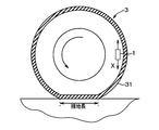
- FIG. 2 is a schematic cross-sectional view of a tire to which a tire side device is attached.
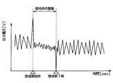
- FIG. 3 is an output voltage waveform diagram of the vibration power generation element during tire rotation.
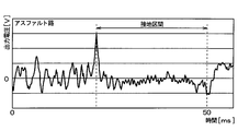
- FIG. 4A is a diagram showing a change in output voltage of the vibration power generation element when traveling on a high ⁇ road surface having a relatively large road surface friction coefficient (hereinafter referred to as ⁇ ) like an asphalt road, FIG.
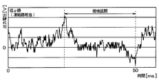
- FIG. 4B is a diagram showing a change in the output voltage of the vibration power generation element when traveling on a low ⁇ road surface where the road surface ⁇ is relatively small like a frozen road
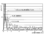
- FIG. 5 is a diagram showing the result of frequency analysis of the output voltage during the grounding section for each of the case where the vehicle is traveling on the high ⁇ road surface and the case where the vehicle is traveling on the low ⁇ road surface.
- FIG. 6 is a diagram illustrating a specific circuit configuration of the signal processing circuit unit when the level of the high frequency component is calculated by integration of the high frequency component extracted during the grounding interval.
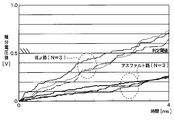
- FIG. 7 is a diagram showing a state of charging with a capacitor in each case where the traveling road surface is a low ⁇ road surface and a high ⁇ road surface.
- the road surface state estimation device is used for estimating a road surface state during traveling based on vibrations on a ground contact surface of a tire provided in each wheel of the vehicle.
- the road surface state estimating device 100 is configured to include a tire side device 1 provided on the tire side and a vehicle side device 2 provided on the vehicle body side. And the road surface condition estimation apparatus 100 transmits the data showing the road surface condition during driving
- the tire side device 1 and the vehicle side device 2 are configured as follows.
- the tire-side device 1 is configured to include a vibration power generation element 11, a power supply circuit 12, a signal processing circuit unit 13, and a transmitter 14, and as shown in FIG. 2, the tire 3 Provided on the back side of the tread 31.
- the vibration power generation element 11 outputs a detection signal corresponding to the vibration in the direction in contact with the circular orbit drawn by the tire side device 1 when the tire 3 rotates, that is, in the tire tangential direction (direction of arrow X in FIG. 2).
- the vibration energy is converted into electric energy, and the power source of the tire side device 1 is generated based on the vibration energy. ing.
- the vibration power generation element 11 is disposed so as to generate power with respect to vibration in the tire tangential direction.
- an electrostatic induction type power generation element for example, an electrostatic induction type power generation element (electret), a piezoelectric element, a friction type, a magnetostriction type, or an electromagnetic induction type element can be applied.
- other devices such as an acceleration sensor may be used as long as the detection signal corresponding to the vibration in the tire tangential direction not taking into account the power generation application is output.
- an electrostatic induction type power generation element when used as the vibration power generation element 11, if the upper electrode charged positively by electrostatic induction is vibrated in the horizontal direction with respect to the lower electrode having a negative charge, Electricity is generated by changing the electric charge due to electrical induction and generating electromotive force. Based on such power generation by the vibration power generation element 11, the power source of the tire side device 1 is generated, and a detection signal corresponding to the magnitude of vibration in the tire tangential direction is generated.
- the vibration power generation element 11 when the vehicle equipped with the road surface condition estimation device 100 travels, vibrations occur in the tread 31 of the tire 3 due to various factors such as the rotational movement of the tire 3 and the unevenness of the road surface.
- this vibration is transmitted to the vibration power generation element 11, power generation by the vibration power generation element 11 is performed, and when this vibration is transmitted to the power supply circuit 12, a power source for the tire side device 1 is generated.
- the signal processing circuit since the output voltage at the time of power generation by the vibration power generation element 11 changes according to the magnitude of vibration, uses the output voltage of the vibration power generation element 11 as a detection signal representing the magnitude of vibration in the tire tangential direction. I tell it to the part 13.
- the output voltage of the vibration power generation element 11 is an alternating voltage because the upper electrode reciprocates due to vibration.
- the power supply circuit 12 is a circuit for storing power based on the output voltage of the vibration power generation element 11 to generate a power source and supplying power to the signal processing circuit unit 13 and the transmitter 14. 16 is provided.
- the rectifier circuit 15 is a known circuit that converts an alternating voltage output from the vibration power generation element 11 into a direct current.
- the AC voltage output from the vibration power generation element 11 is DC converted by the rectifier circuit 15 and output to the power storage circuit 16.
- the rectifier circuit 15 may be a full-wave rectifier circuit or a half-wave rectifier circuit.
- the accumulator circuit 16 is a circuit for accumulating the DC voltage applied from the rectifier circuit 15, and is constituted by a capacitor or the like.
- the output voltage of the vibration power generation element 11 is stored in the power storage circuit 16 via the rectifier circuit 15, and the voltage stored here is used as a power source to the signal processing circuit unit 13 and the transmitter 14 provided in the tire side device 1. Power is being supplied. Further, since the power supply circuit 12 includes the power storage circuit 16, when the vibration power generation element 11 is generating excessive power, the surplus is stored, and when the power generation amount is insufficient, the shortage is stored. It comes to be able to compensate.
- the signal processing circuit unit 13 is a part corresponding to the signal processing unit, and uses the output voltage of the vibration power generation element 11 as a detection signal representing vibration data in the tire tangential direction, and processes this detection signal to thereby determine the road surface condition. It is responsible for obtaining the data it represents and communicating it to the transmitter 14. That is, the signal processing circuit unit 13 is based on the time change of the output voltage of the vibration power generation element 11 and the grounding section of the vibration power generation element 11 when the tire 3 rotates (that is, the vibration power generation element 11 of the tread 31 of the tire 3). The section in which the portion corresponding to the arrangement location is grounded on the road surface) is extracted. Then, since the high frequency component included in the detection signal in the ground contact section of the vibration power generation element 11 represents the road surface condition, the high frequency component is extracted and data representing the road surface condition is generated based on the extracted high frequency component. To the transmitter 14.
- the signal processing circuit unit 13 is configured by a known microcomputer having various circuits, a CPU, a ROM, a RAM, an I / O, and the like, and performs the above processing based on the output voltage of the vibration power generation element 11. Is going.
- the signal processing circuit unit 13 includes a ground section extraction unit 17 and a high frequency level calculation unit 18 as parts for performing these processes.
- the grounding section extraction unit 17 extracts the grounding section of the vibration power generation element 11 by detecting the peak value of the detection signal represented by the output voltage of the vibration power generation element 11, and calculates the high frequency level that it is in the grounding section. Tell part 18. Further, the contact section extraction unit 17 generates a transmission trigger that causes the transmitter 14 to transmit the calculation result of the high-frequency level calculation unit 18 to the vehicle-side device 2 as road surface state data representing the road surface state.
- the function of the contact section extraction unit 17 will be specifically described.
- the output voltage (unit: V) waveform of the vibration power generation element 11 when the tire rotates is, for example, the waveform shown in FIG.
- the output voltage of the vibration power generation element 11 reaches the maximum value at the start of grounding when the portion corresponding to the arrangement position of the vibration power generation element 11 of the tread 31 starts to ground as the tire 3 rotates.
- the grounding section extraction unit 17 detects the timing of the first peak value at which the output voltage of the vibration power generation element 11 takes the maximum value as the grounding start time. Further, as shown in FIG. 3, when the tire 3 rotates, the portion of the tread 31 corresponding to the position where the vibration power generation element 11 is disposed is grounded from the state where the vibration power generation element 11 is not grounded. Output voltage takes the minimum value.
- the grounding section extraction unit 17 detects the timing of the second peak value at which the output voltage of the vibration power generation element 11 takes the minimum value as the end of grounding.
- the reason why the vibration power generation element 11 takes the peak value at the above timing is as follows. That is, when the portion of the tread 31 corresponding to the placement location of the vibration power generation element 11 comes into contact with the rotation of the tire 3, the portion of the tire 3 that has been substantially cylindrical in the vicinity of the vibration power generation element 11 is It is pressed and deformed into a flat shape. By receiving the impact at this time, the output voltage of the vibration power generation element 11 takes the first peak value. Further, when the portion of the tread 31 corresponding to the place where the vibration power generation element 11 is disposed is separated from the grounding surface as the tire 3 rotates, the tire 3 is released from pressing in the vicinity of the vibration power generation element 11 and is planar. To return to a substantially cylindrical shape.
- the output voltage of the vibration power generation element 11 takes the second peak value.
- the vibration power generation element 11 takes the first and second peak values when the grounding starts and when the grounding ends, respectively.
- the sign of the output voltage is also opposite.
- the contact section extraction unit 17 transmits the timings of the first and second peak values to the high frequency level calculation unit 18, and the output of the vibration power generation element 11 during the period from the timing of the first peak value to the timing of the second peak value.
- An instruction to rectify and integrate the high frequency component contained in the voltage is issued.
- the grounding section extraction unit 17 extracts the grounding section of the vibration power generation element 11 and notifies the high frequency level calculation unit 18 that it is in the grounding section.
- the grounding section extraction unit 17 sends a transmission trigger to the transmitter 14 at this timing. .
- the transmitter 14 transmits the calculation result transmitted from the high frequency level calculation unit 18 as road surface condition data. In this way, data transmission by the transmitter 14 is not always performed, but only when the vibration power generation element 11 is grounded, so that power consumption can be reduced.
- the high frequency level calculation unit 18 determines the level of the high frequency component caused by the vibration of the tire 3 included in the output voltage of the vibration power generation element 11 during the period. calculate. Then, the high frequency level calculation unit 18 transmits the calculation result to the transmitter 14 as road surface condition data representing the road surface condition.
- the level of the high frequency component is calculated as an index representing the road surface condition, and the reason will be described with reference to FIGS. 4A, 4B, and 5.
- FIG. 4A shows a change in the output voltage (unit: V) of the vibration power generation element 11 when traveling on a high ⁇ road surface having a relatively large road surface ⁇ such as an asphalt road.
- FIG. 4B shows a change in the output voltage (unit: V) of the vibration power generation element 11 when traveling on a low ⁇ road surface having a relatively small road surface ⁇ such as a frozen road.
- the first and second peak values appear at the beginning and end of the grounding section, that is, at the start and end of grounding of the vibration power generation element 11, regardless of the road surface ⁇ .
- the road surface ⁇ due to the influence of the road surface ⁇ , when the vehicle is traveling on a low ⁇ road surface, fine high-frequency vibration due to the slip of the tire 3 is superimposed on the output voltage. For this reason, when the frequency analysis of the output voltage in the grounding section is performed for each of the case where the vehicle is traveling on the high ⁇ road surface and the case where the vehicle is traveling on the low ⁇ road surface, the result shown in FIG. 5 is obtained.
- the level of the high frequency component of the output voltage of the vibration power generation element 11 is an index representing the road surface condition.
- the level of the high frequency component of the output voltage of the vibration power generation element 11 during the grounding section can be used as road surface condition data.
- the level of the high frequency component can be calculated by extracting the high frequency component from the output voltage of the vibration power generation element and integrating the extracted high frequency component during the grounding section.
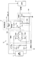
- FIG. 6 is a diagram showing a specific circuit configuration of the signal processing circuit unit 13 applied when the level of the high frequency component is calculated by integration of the high frequency component extracted during the grounding section.
- the ground section extraction unit 17 receives the detection signal (output voltage) of the vibration power generation element 11, outputs an integration instruction signal to the high frequency level calculation unit 18 based on the analysis result of the detection signal, and transmits the transmitter 14.
- a transmission trigger is output for.
- the ground segment extraction unit 17 includes a ground pulse detection unit 171, and the ground pulse detection unit 171 detects the peak of the detection signal when the vibration power generation element 11 is grounded and when the grounding is terminated. ing. Then, the ground pulse detection unit 171 outputs an integration instruction signal when the detection signal of the vibration power generation element 11 reaches the first peak value, and cancels the integration instruction signal when the detection signal reaches the second peak value.
- the switch 172 when a high level is output as an integration instruction signal from the ground pulse detector 171, the switch 172 is turned on, and when it is inverted by the inverter 173 and a low level is transmitted, the switch 174 is turned off and the high frequency component is turned on. Integration of starts.
- the switch 172 is turned off, and when it is inverted by the inverter 173 and a high level is transmitted, the switch 174 is turned on and the high frequency component is generated. Integration is terminated.
- the high-frequency level calculation unit 18 includes a high-pass filter unit 181, a rectification unit 182, and an integration unit 183.
- the high-pass filter unit 181 corresponds to a high-frequency component extraction unit that extracts a high-frequency component of the detection signal of the vibration power generation element 11.
- the high-pass filter unit 181 is configured by a CR filter circuit having capacitors 181a and 181b and a resistor 181c. Only the high-frequency component of the detection signal of the vibration power generation element 11 is adjusted by adjusting the capacitance values of the capacitors 181a and 181b and the resistance value of the resistor 181c. Pass through.
- the rectifying unit 182 is configured by a full-wave rectifier circuit having diodes 182a to 182d arranged in a bridge shape, and full-wave rectifies the high-frequency component of the detection signal extracted by the high-pass filter unit 181. Thereby, only the positive voltage after full-wave rectification can be applied to the integrating unit 183.
- the integrating unit 183 is a part that integrates the high-frequency component of the detection signal of the vibration power generation element 11, and in this embodiment, the integrating unit 183 has a configuration including a capacitor 183a and a resistor 183b.
- the capacitor 183a is charged based on the high-frequency component after full-wave rectification.
- the charging voltage of the capacitor 183a corresponds to a value obtained by integrating the high frequency component, and the integrated voltage value of the capacitor 183a is input to the transmitter 14 as data representing the road surface condition. That is, as shown in FIG. 5, the level of the high frequency component of the detection signal of the vibration power generation element 11 is different between the case where the traveling road surface is a low ⁇ road surface and the case where the road surface is a high ⁇ road surface. Accordingly, the integrated voltage value of the capacitor 183a changes.
- the resistor 183b is connected to the capacitor 183a to discharge the capacitor 183a when the ground pulse detector 171 releases the integration instruction signal and the switch 174 is turned on. As a result, the voltage of the capacitor 183a can be reset to 0 when the high-frequency component is integrated next time.
- the signal processing circuit unit 13 can be configured by such a circuit, and the high frequency component of the output voltage of the vibration power generation element 11 is integrated by the integration unit 183, thereby calculating the level of the high frequency component in the grounding section. be able to.
- the transmitter 14 transmits road surface condition data transmitted from the signal processing circuit unit 13 to the vehicle-side device 2.
- Communication between the transmitter 14 and the receiver 21 included in the vehicle-side device 2 can be performed by a known short-range wireless communication technology such as Bluetooth (registered trademark).
- the timing for transmitting the road surface condition data is arbitrary, but as described above, in the present embodiment, the transmission trigger is sent from the grounding section extraction unit 17 when the grounding of the vibration power generation element 11 is finished, so that the road surface from the transmitter 14 is transmitted. Status data is sent. In this way, data transmission by the transmitter 14 is not always performed, but only when the vibration power generation element 11 is grounded, so that power consumption can be reduced.
- road surface condition data it can also send with the specific recognition information (ID information) of the wheel previously provided for every tire 3 with which the vehicle was equipped.
- ID information specific recognition information
- the position of each wheel can be specified by a well-known wheel position detection device that detects which position of the vehicle the wheel is attached to. Therefore, by transmitting road surface condition data together with ID information to the vehicle side device 2, which wheel is detected. It is possible to determine whether it is the data.
- the road surface ⁇ of the road surface is assumed to be uniform, but there are ⁇ split roads with different road surface ⁇ between the left and right wheels of the vehicle, and on such ⁇ split roads road surface condition data is transmitted for each wheel.
- the average value of the integrated voltage value indicated by the road surface data sent from each wheel is used to estimate the road surface condition. You may make it use for estimation of.
- the vehicle-side device 2 is configured to include a receiver 21 and a road surface condition estimation unit 22, and receives road surface condition data transmitted from the tire-side device 1, and performs various processes based on this data. By doing so, the road surface condition while traveling is detected.
- the receiver 21 is a device for receiving road surface condition data transmitted by the tire side device 1.
- the road surface condition data received by the receiver 21 is sequentially output to the road surface state estimation unit 22 every time it is received.
- the road surface condition estimation unit 22 is configured by a known microcomputer including a CPU, ROM, RAM, I / O, and the like, and performs processing for detecting road surface conditions in accordance with a program stored in the ROM or the like. Specifically, the road surface state estimation unit 22 estimates the road surface ⁇ based on the magnitude of the integrated voltage value indicated by the road surface state data. For example, if the integrated voltage value is larger than the determination threshold, the road surface is low ⁇ . If the road surface is small, the traveling road surface is determined to be a high ⁇ road surface. As shown in FIG.
- the determination threshold is set to an intermediate value between an integrated voltage value assumed when the traveling road surface is a low ⁇ road surface and an integrated voltage value assumed when the traveling road surface is a high ⁇ road surface. For this reason, it is possible to estimate the road surface condition of the traveling road surface by comparing with the determination threshold value.
- the estimation result is placed in, for example, CAN (Controller ⁇ Area Network) (registered trademark) communication that is an in-vehicle network.
- the estimation result of the road surface condition is input to, for example, an electronic control device (brake ECU) for brake control, and is used to set an index for performing antilock brake control, for example, a control start threshold value in antilock brake control.
- the tire-side device 1 calculates the level of the high-frequency component of the detection signal of the vibration power generation element 11 during the ground contact section of the tire 3, and calculates the road surface state. It is sent as data. And the road surface condition data is received by the vehicle side apparatus 2, and the road surface condition of the traveling road surface is estimated. As a result, it is possible to estimate the road surface condition without performing frequency analysis, thereby reducing power consumption and reducing frequency analysis components. Therefore, cost reduction can be achieved.
- the signal processing circuit unit 13 extracts the high frequency component by passing the detection signal of the vibration power generation element 11 through the high pass filter unit 181, and then charges the capacitor 183 a after rectification until the grounding of the vibration power generation element 11 is completed.
- the integrated voltage value is obtained.
- portions other than the ground pulse detection unit 171 in the signal processing circuit unit 13 can be configured mainly by analog circuits, so that signal processing can be performed with a low-cost and space-saving circuit.
- the tire side apparatus 1 should just transmit the integrated voltage value by the capacitor
- the road surface condition is estimated by comparing the integrated voltage value transmitted from the tire-side device 1 with the constant determination threshold value in the vehicle-side device 2, but the determination threshold value may be variable.
- the vibration generated in the tire 3 changes according to the vehicle speed, and the vibration generated in the tire 3 increases as the vehicle speed increases even under the same road surface condition.
- the high-frequency component included in the detection signal of the vibration power generation element 11 also increases, and the integrated voltage value charged in the capacitor 183a also increases. Therefore, for example, the vehicle speed data can be input to the road surface condition estimation unit 22, and the determination threshold can be changed to a larger value as the vehicle speed indicated by the vehicle speed data increases.
- the vehicle speed data for example, data calculated by an in-vehicle ECU (electronic control unit) based on detection signals from a vehicle speed sensor or a wheel speed sensor may be acquired through CAN communication.
- the ground pulse detector 171 extracts the high frequency component of the detection signal of the vibration power generation element 11 from the start of grounding of the vibration power generation element 11 to the end of the grounding, that is, during the grounding time.
- the integrated voltage value was obtained by charging the capacitor 183a with the high frequency component.
- this shows an example of the charging time when obtaining the integrated voltage value.
- a certain period from the start of grounding of the vibration power generation element 11 may be set as the charging time when obtaining the integrated voltage value.
- the charging time can be assumed as the grounding time of the vibration power generation element 11 when the vehicle travels at a speed of 60 km / h.
Landscapes
- Engineering & Computer Science (AREA)
- Mechanical Engineering (AREA)
- Physics & Mathematics (AREA)
- Automation & Control Theory (AREA)
- Mathematical Physics (AREA)
- Transportation (AREA)
- Tires In General (AREA)
- Control Of Driving Devices And Active Controlling Of Vehicle (AREA)
Priority Applications (2)
| Application Number | Priority Date | Filing Date | Title |
|---|---|---|---|
| DE112015001319.9T DE112015001319B4 (de) | 2014-03-18 | 2015-03-12 | Strassenoberflächenzustandsschätzvorrichtung |
| US15/122,218 US10099699B2 (en) | 2014-03-18 | 2015-03-12 | Road surface condition estimation device |
Applications Claiming Priority (2)
| Application Number | Priority Date | Filing Date | Title |
|---|---|---|---|
| JP2014054929A JP6273937B2 (ja) | 2014-03-18 | 2014-03-18 | 路面状況推定装置 |
| JP2014-054929 | 2014-03-18 |
Publications (1)
| Publication Number | Publication Date |
|---|---|
| WO2015141199A1 true WO2015141199A1 (ja) | 2015-09-24 |
Family
ID=54144183
Family Applications (1)
| Application Number | Title | Priority Date | Filing Date |
|---|---|---|---|
| PCT/JP2015/001394 Ceased WO2015141199A1 (ja) | 2014-03-18 | 2015-03-12 | 路面状況推定装置 |
Country Status (4)
| Country | Link |
|---|---|
| US (1) | US10099699B2 (enExample) |
| JP (1) | JP6273937B2 (enExample) |
| DE (1) | DE112015001319B4 (enExample) |
| WO (1) | WO2015141199A1 (enExample) |
Cited By (9)
| Publication number | Priority date | Publication date | Assignee | Title |
|---|---|---|---|---|
| US9713944B2 (en) | 2014-03-18 | 2017-07-25 | Denso Corporation | Tire condition detection device |
| US9827815B2 (en) | 2013-03-15 | 2017-11-28 | Denso Corporation | Tire device |
| FR3052420A1 (fr) * | 2016-06-14 | 2017-12-15 | Continental Automotive France | Procede de determination de l'etat d'une route |
| US9950578B2 (en) | 2014-05-14 | 2018-04-24 | Denso Corporation | Tire air pressure detection device |
| US10029681B2 (en) | 2014-03-18 | 2018-07-24 | Denso Corporation | Vehicle erroneous start control device |
| US10086842B2 (en) | 2014-03-18 | 2018-10-02 | Denso Corporation | Road surface condition estimation device |
| CN109613542A (zh) * | 2017-10-04 | 2019-04-12 | 赫拉胡克两合公司 | 用于检测行车道上的湿气的方法 |
| US20190187029A1 (en) * | 2016-08-05 | 2019-06-20 | Denso Corporation | Tire-mounted sensor and chain regulation management system |
| US20240035824A1 (en) * | 2020-12-10 | 2024-02-01 | National Institute Of Advanced Industrial Science And Technology | Information processing device, information processing method, and non-transitory computer readable medium |
Families Citing this family (16)
| Publication number | Priority date | Publication date | Assignee | Title |
|---|---|---|---|---|
| JP6488986B2 (ja) | 2015-10-27 | 2019-03-27 | 株式会社Soken | 路面状況推定装置 |
| JP6365503B2 (ja) * | 2015-10-27 | 2018-08-01 | 株式会社Soken | 路面状況推定装置 |
| JP6558266B2 (ja) * | 2016-02-19 | 2019-08-14 | 株式会社デンソー | 車両用危険回避装置 |
| JP6601261B2 (ja) * | 2016-02-23 | 2019-11-06 | 株式会社Soken | 路面状況推定装置 |
| JP2017198507A (ja) * | 2016-04-26 | 2017-11-02 | 株式会社デンソー | 路面状態検出装置 |
| JP6544302B2 (ja) | 2016-06-22 | 2019-07-17 | 株式会社Soken | 路面状況推定装置 |
| JP6551463B2 (ja) * | 2016-07-13 | 2019-07-31 | 株式会社デンソー | タイヤマウントセンサおよびそれを含む路面状態推定装置 |
| JP6620787B2 (ja) * | 2016-08-11 | 2019-12-18 | 株式会社デンソー | 路面状態推定装置 |
| JP6547793B2 (ja) | 2016-08-12 | 2019-07-24 | 株式会社デンソー | タイヤマウントセンサ、ダイアグ履歴記憶装置およびダイアグ報知装置 |
| JP6614073B2 (ja) | 2016-09-06 | 2019-12-04 | 株式会社デンソー | 路面状態推定装置 |
| JP6930355B2 (ja) * | 2017-10-11 | 2021-09-01 | 株式会社Soken | 路面状態判別装置およびそれを備えたタイヤシステム |
| JP6946970B2 (ja) * | 2017-11-23 | 2021-10-13 | 株式会社デンソー | 路面状態判別装置 |
| JP6777103B2 (ja) * | 2018-01-19 | 2020-10-28 | 株式会社Soken | 路面状態判別装置およびそれを含むタイヤシステム |
| JP7047466B2 (ja) * | 2018-03-02 | 2022-04-05 | 株式会社Soken | 路面状態判別装置 |
| JP7415380B2 (ja) * | 2019-09-04 | 2024-01-17 | 株式会社Soken | タイヤ側装置およびそれを含む路面状態判別装置 |
| KR102267901B1 (ko) | 2019-10-02 | 2021-06-24 | 한국타이어앤테크놀로지 주식회사 | 노면 상태 추정 장치 및 이를 이용한 노면 상태 추정 방법 |
Citations (4)
| Publication number | Priority date | Publication date | Assignee | Title |
|---|---|---|---|---|
| WO2006135090A1 (ja) * | 2005-06-17 | 2006-12-21 | Kabushiki Kaisha Bridgestone | 路面状態推定方法、路面状態推定用タイヤ、路面状態推定装置、及び、車両制御装置 |
| JP2008100610A (ja) * | 2006-10-19 | 2008-05-01 | Yokohama Rubber Co Ltd:The | 走行路面状態検出システム及びそのセンサユニット |
| JP2010533844A (ja) * | 2007-07-18 | 2010-10-28 | ピレリ・タイヤ・ソチエタ・ペル・アツィオーニ | 車両の走行中のタイヤの動作パラメータを決定するための方法およびシステム |
| JP2011046256A (ja) * | 2009-08-26 | 2011-03-10 | Bridgestone Corp | 路面状態の推定方法とその装置、及び、車両制御方法 |
Family Cites Families (8)
| Publication number | Priority date | Publication date | Assignee | Title |
|---|---|---|---|---|
| JP4517610B2 (ja) * | 2003-09-16 | 2010-08-04 | トヨタ自動車株式会社 | タイヤ状態量検出装置 |
| JP4127206B2 (ja) * | 2003-12-25 | 2008-07-30 | トヨタ自動車株式会社 | タイヤおよび車輪情報処理装置 |
| JP4349151B2 (ja) * | 2004-02-26 | 2009-10-21 | トヨタ自動車株式会社 | 接触状態取得装置 |
| JP2006142993A (ja) * | 2004-11-19 | 2006-06-08 | Yokohama Rubber Co Ltd:The | 加速度センサ装着タイヤ |
| DE102008041608B4 (de) | 2008-08-27 | 2021-08-12 | Robert Bosch Gmbh | Verfahren zur Detektion von Beschleunigungspeaks in Reifen |
| JP5657917B2 (ja) | 2010-05-19 | 2015-01-21 | 株式会社ブリヂストン | 路面状態推定方法 |
| JP6033619B2 (ja) | 2012-09-13 | 2016-11-30 | テイ・エス テック株式会社 | 車両用シート |
| JP6281346B2 (ja) | 2014-03-18 | 2018-02-21 | 株式会社Soken | 路面状況推定装置 |
-
2014
- 2014-03-18 JP JP2014054929A patent/JP6273937B2/ja not_active Expired - Fee Related
-
2015
- 2015-03-12 WO PCT/JP2015/001394 patent/WO2015141199A1/ja not_active Ceased
- 2015-03-12 US US15/122,218 patent/US10099699B2/en active Active
- 2015-03-12 DE DE112015001319.9T patent/DE112015001319B4/de not_active Expired - Fee Related
Patent Citations (4)
| Publication number | Priority date | Publication date | Assignee | Title |
|---|---|---|---|---|
| WO2006135090A1 (ja) * | 2005-06-17 | 2006-12-21 | Kabushiki Kaisha Bridgestone | 路面状態推定方法、路面状態推定用タイヤ、路面状態推定装置、及び、車両制御装置 |
| JP2008100610A (ja) * | 2006-10-19 | 2008-05-01 | Yokohama Rubber Co Ltd:The | 走行路面状態検出システム及びそのセンサユニット |
| JP2010533844A (ja) * | 2007-07-18 | 2010-10-28 | ピレリ・タイヤ・ソチエタ・ペル・アツィオーニ | 車両の走行中のタイヤの動作パラメータを決定するための方法およびシステム |
| JP2011046256A (ja) * | 2009-08-26 | 2011-03-10 | Bridgestone Corp | 路面状態の推定方法とその装置、及び、車両制御方法 |
Cited By (14)
| Publication number | Priority date | Publication date | Assignee | Title |
|---|---|---|---|---|
| US9827815B2 (en) | 2013-03-15 | 2017-11-28 | Denso Corporation | Tire device |
| US10029681B2 (en) | 2014-03-18 | 2018-07-24 | Denso Corporation | Vehicle erroneous start control device |
| US10086842B2 (en) | 2014-03-18 | 2018-10-02 | Denso Corporation | Road surface condition estimation device |
| US9713944B2 (en) | 2014-03-18 | 2017-07-25 | Denso Corporation | Tire condition detection device |
| US9950578B2 (en) | 2014-05-14 | 2018-04-24 | Denso Corporation | Tire air pressure detection device |
| WO2017216466A1 (fr) * | 2016-06-14 | 2017-12-21 | Continental Automotive France | Procédé de détermination de l'état d'une route |
| FR3052420A1 (fr) * | 2016-06-14 | 2017-12-15 | Continental Automotive France | Procede de determination de l'etat d'une route |
| CN109311481A (zh) * | 2016-06-14 | 2019-02-05 | 法国大陆汽车公司 | 用于确定道路状态的方法 |
| US10668927B2 (en) | 2016-06-14 | 2020-06-02 | Continental Automotive France | Method of determining the state of a road |
| CN109311481B (zh) * | 2016-06-14 | 2021-10-08 | 法国大陆汽车公司 | 用于确定道路状态的方法 |
| US20190187029A1 (en) * | 2016-08-05 | 2019-06-20 | Denso Corporation | Tire-mounted sensor and chain regulation management system |
| CN109613542A (zh) * | 2017-10-04 | 2019-04-12 | 赫拉胡克两合公司 | 用于检测行车道上的湿气的方法 |
| CN109613542B (zh) * | 2017-10-04 | 2023-09-08 | 赫拉胡克两合公司 | 用于检测行车道上的湿气的方法 |
| US20240035824A1 (en) * | 2020-12-10 | 2024-02-01 | National Institute Of Advanced Industrial Science And Technology | Information processing device, information processing method, and non-transitory computer readable medium |
Also Published As
| Publication number | Publication date |
|---|---|
| DE112015001319T5 (de) | 2016-12-01 |
| JP6273937B2 (ja) | 2018-02-07 |
| JP2015174637A (ja) | 2015-10-05 |
| US20160368501A1 (en) | 2016-12-22 |
| US10099699B2 (en) | 2018-10-16 |
| DE112015001319B4 (de) | 2020-07-30 |
Similar Documents
| Publication | Publication Date | Title |
|---|---|---|
| JP6273937B2 (ja) | 路面状況推定装置 | |
| JP6281346B2 (ja) | 路面状況推定装置 | |
| JP6365503B2 (ja) | 路面状況推定装置 | |
| US10866161B2 (en) | Road surface condition estimation apparatus | |
| JP6488986B2 (ja) | 路面状況推定装置 | |
| JP6318743B2 (ja) | タイヤ状態検出装置 | |
| US10471959B2 (en) | Vehicle control device | |
| US11034356B2 (en) | Tire-mounted sensor and road surface condition estimation apparatus including the same | |
| JP6372214B2 (ja) | タイヤ状態検出装置 | |
| JP2018009974A (ja) | タイヤマウントセンサおよびそれを含む路面状態推定装置 | |
| WO2014141690A1 (ja) | タイヤ装置 | |
| JP6601261B2 (ja) | 路面状況推定装置 | |
| WO2018003693A1 (ja) | タイヤマウントセンサおよびそれを含む路面状態推定装置 | |
| JP6119330B6 (ja) | タイヤ装置 |
Legal Events
| Date | Code | Title | Description |
|---|---|---|---|
| 121 | Ep: the epo has been informed by wipo that ep was designated in this application |
Ref document number: 15765538 Country of ref document: EP Kind code of ref document: A1 |
|
| WWE | Wipo information: entry into national phase |
Ref document number: 15122218 Country of ref document: US |
|
| WWE | Wipo information: entry into national phase |
Ref document number: 112015001319 Country of ref document: DE |
|
| 122 | Ep: pct application non-entry in european phase |
Ref document number: 15765538 Country of ref document: EP Kind code of ref document: A1 |