WO2015141122A1 - ワーク保持装置 - Google Patents
ワーク保持装置 Download PDFInfo
- Publication number
- WO2015141122A1 WO2015141122A1 PCT/JP2015/000703 JP2015000703W WO2015141122A1 WO 2015141122 A1 WO2015141122 A1 WO 2015141122A1 JP 2015000703 W JP2015000703 W JP 2015000703W WO 2015141122 A1 WO2015141122 A1 WO 2015141122A1
- Authority
- WO
- WIPO (PCT)
- Prior art keywords
- workpiece
- air
- suction pad
- work
- opening
- Prior art date
- Legal status (The legal status is an assumption and is not a legal conclusion. Google has not performed a legal analysis and makes no representation as to the accuracy of the status listed.)
- Ceased
Links
Images




Classifications
-
- H—ELECTRICITY
- H10—SEMICONDUCTOR DEVICES; ELECTRIC SOLID-STATE DEVICES NOT OTHERWISE PROVIDED FOR
- H10P—GENERIC PROCESSES OR APPARATUS FOR THE MANUFACTURE OR TREATMENT OF DEVICES COVERED BY CLASS H10
- H10P72/00—Handling or holding of wafers, substrates or devices during manufacture or treatment thereof
- H10P72/70—Handling or holding of wafers, substrates or devices during manufacture or treatment thereof for supporting or gripping
- H10P72/78—Handling or holding of wafers, substrates or devices during manufacture or treatment thereof for supporting or gripping using vacuum or suction, e.g. Bernoulli chucks
-
- B—PERFORMING OPERATIONS; TRANSPORTING
- B24—GRINDING; POLISHING
- B24B—MACHINES, DEVICES, OR PROCESSES FOR GRINDING OR POLISHING; DRESSING OR CONDITIONING OF ABRADING SURFACES; FEEDING OF GRINDING, POLISHING, OR LAPPING AGENTS
- B24B37/00—Lapping machines or devices; Accessories
- B24B37/34—Accessories
- B24B37/345—Feeding, loading or unloading work specially adapted to lapping
-
- B—PERFORMING OPERATIONS; TRANSPORTING
- B24—GRINDING; POLISHING
- B24B—MACHINES, DEVICES, OR PROCESSES FOR GRINDING OR POLISHING; DRESSING OR CONDITIONING OF ABRADING SURFACES; FEEDING OF GRINDING, POLISHING, OR LAPPING AGENTS
- B24B41/00—Component parts such as frames, beds, carriages, headstocks
- B24B41/06—Work supports, e.g. adjustable steadies
-
- B—PERFORMING OPERATIONS; TRANSPORTING
- B25—HAND TOOLS; PORTABLE POWER-DRIVEN TOOLS; MANIPULATORS
- B25J—MANIPULATORS; CHAMBERS PROVIDED WITH MANIPULATION DEVICES
- B25J15/00—Gripping heads and other end effectors
- B25J15/06—Gripping heads and other end effectors with vacuum or magnetic holding means
- B25J15/0616—Gripping heads and other end effectors with vacuum or magnetic holding means with vacuum
- B25J15/065—Gripping heads and other end effectors with vacuum or magnetic holding means with vacuum provided with separating means for releasing the gripped object after suction
- B25J15/0658—Pneumatic type, e.g. air blast or overpressure
-
- B—PERFORMING OPERATIONS; TRANSPORTING
- B25—HAND TOOLS; PORTABLE POWER-DRIVEN TOOLS; MANIPULATORS
- B25J—MANIPULATORS; CHAMBERS PROVIDED WITH MANIPULATION DEVICES
- B25J15/00—Gripping heads and other end effectors
- B25J15/06—Gripping heads and other end effectors with vacuum or magnetic holding means
- B25J15/0616—Gripping heads and other end effectors with vacuum or magnetic holding means with vacuum
- B25J15/065—Gripping heads and other end effectors with vacuum or magnetic holding means with vacuum provided with separating means for releasing the gripped object after suction
- B25J15/0666—Other types, e.g. pins or springs
-
- B—PERFORMING OPERATIONS; TRANSPORTING
- B25—HAND TOOLS; PORTABLE POWER-DRIVEN TOOLS; MANIPULATORS
- B25J—MANIPULATORS; CHAMBERS PROVIDED WITH MANIPULATION DEVICES
- B25J15/00—Gripping heads and other end effectors
- B25J15/06—Gripping heads and other end effectors with vacuum or magnetic holding means
- B25J15/0616—Gripping heads and other end effectors with vacuum or magnetic holding means with vacuum
- B25J15/0683—Details of suction cup structure, e.g. grooves or ridges
-
- H—ELECTRICITY
- H10—SEMICONDUCTOR DEVICES; ELECTRIC SOLID-STATE DEVICES NOT OTHERWISE PROVIDED FOR
- H10P—GENERIC PROCESSES OR APPARATUS FOR THE MANUFACTURE OR TREATMENT OF DEVICES COVERED BY CLASS H10
- H10P52/00—Grinding, lapping or polishing of wafers, substrates or parts of devices
-
- H—ELECTRICITY
- H10—SEMICONDUCTOR DEVICES; ELECTRIC SOLID-STATE DEVICES NOT OTHERWISE PROVIDED FOR
- H10P—GENERIC PROCESSES OR APPARATUS FOR THE MANUFACTURE OR TREATMENT OF DEVICES COVERED BY CLASS H10
- H10P72/00—Handling or holding of wafers, substrates or devices during manufacture or treatment thereof
- H10P72/70—Handling or holding of wafers, substrates or devices during manufacture or treatment thereof for supporting or gripping
- H10P72/74—Handling or holding of wafers, substrates or devices during manufacture or treatment thereof for supporting or gripping using temporarily an auxiliary support
-
- H—ELECTRICITY
- H10—SEMICONDUCTOR DEVICES; ELECTRIC SOLID-STATE DEVICES NOT OTHERWISE PROVIDED FOR
- H10P—GENERIC PROCESSES OR APPARATUS FOR THE MANUFACTURE OR TREATMENT OF DEVICES COVERED BY CLASS H10
- H10P72/00—Handling or holding of wafers, substrates or devices during manufacture or treatment thereof
- H10P72/70—Handling or holding of wafers, substrates or devices during manufacture or treatment thereof for supporting or gripping
- H10P72/76—Handling or holding of wafers, substrates or devices during manufacture or treatment thereof for supporting or gripping using mechanical means, e.g. clamps or pinches
- H10P72/7604—Handling or holding of wafers, substrates or devices during manufacture or treatment thereof for supporting or gripping using mechanical means, e.g. clamps or pinches the wafers being placed on a susceptor, stage or support
-
- H—ELECTRICITY
- H10—SEMICONDUCTOR DEVICES; ELECTRIC SOLID-STATE DEVICES NOT OTHERWISE PROVIDED FOR
- H10P—GENERIC PROCESSES OR APPARATUS FOR THE MANUFACTURE OR TREATMENT OF DEVICES COVERED BY CLASS H10
- H10P72/00—Handling or holding of wafers, substrates or devices during manufacture or treatment thereof
- H10P72/70—Handling or holding of wafers, substrates or devices during manufacture or treatment thereof for supporting or gripping
- H10P72/76—Handling or holding of wafers, substrates or devices during manufacture or treatment thereof for supporting or gripping using mechanical means, e.g. clamps or pinches
- H10P72/7604—Handling or holding of wafers, substrates or devices during manufacture or treatment thereof for supporting or gripping using mechanical means, e.g. clamps or pinches the wafers being placed on a susceptor, stage or support
- H10P72/7624—Handling or holding of wafers, substrates or devices during manufacture or treatment thereof for supporting or gripping using mechanical means, e.g. clamps or pinches the wafers being placed on a susceptor, stage or support characterised by the mechanical construction of the susceptor, stage or support
Definitions
- the present invention relates to an apparatus for holding a workpiece when a workpiece such as a silicon wafer is conveyed.
- wafers are generally transported between processes using a box or cassette having a plurality of slots for storing wafers one by one.
- the transported box or cassette is set in a processing apparatus in a transport destination process, and a wafer is taken out of the box and cassette and set in a processing apparatus. Then, the processed wafer is again stored in a box or cassette and sent to the next process.
- wafer transfer such as taking out the wafer from the cassette or box, setting it to the processing device, and storing it in the box or cassette after the processing is completed automatically without human intervention by a robot or actuator.
- a hand hereinafter also referred to as a work holding device
- an actuator or the like holds the wafer, moves to the transfer destination, and releases the wafer there (see Patent Document 1).
- a method such as suction adsorption, edge grip, or Bernoulli chuck is generally used for holding the wafer.
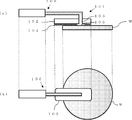
- the work holding device 101 is provided with an air control mechanism 106 and a vent hole 103.
- air is drawn, and when the work W is to be separated (detached), the suction is stopped. Alternatively, air is supplied to further promote separation.
- the suction pad 104 having elasticity is generally attached to the work holding unit. The suction pad 104 sucks air into the opening 105 to suck the work W.
- the suction effect can be enhanced by increasing the adhesion between the workpiece W and the holding portion by the suction pad 104, and further, the workpiece 102 can be prevented from being scratched by the direct contact between the main body 102 of the holding device and the workpiece W. Can be prevented.
- the fact that the wafer is wet means that when the wafer is sucked and held by the holding device, a liquid is interposed between the suction pad and the wafer.
- the wafer is adsorbed to the work holding device mainly by vacuum, but this intervening liquid also generates an adsorbing force between the adsorbing pad and the wafer. Therefore, when the vacuum is turned off, the suction force due to the vacuum disappears, but the suction force due to the liquid remains, causing a problem that the wafer is not separated from the work holding device.
- the wafer cannot be accurately placed at the intended position in the wafer handling apparatus. Furthermore, even when you want to turn off the vacuum and remove the wafer, the wafer sticks to the suction pad due to the suction force of the liquid. May be damaged. As a result, there arises a problem that the yield is lowered and the machine productivity is lowered due to the occurrence of the apparatus restoration work.
- An object of the present invention is to provide a work holding device that can be used.
- a rigid body having a vent and an opening bonded to the lower end surface of the rigid body and communicated with the vent are used for adsorbing and holding a workpiece.
- a suction pad, and an air control mechanism that communicates with the vent hole and sucks or discharges air from the opening by sucking or discharging air from the vent hole, and contacts the workpiece with the opening. While sucking air with the air control mechanism and sucking air from the opening, the work is sucked and held on the suction pad, and air is discharged from the air control mechanism to discharge from the opening.
- a work holding device that detaches the work from the suction pad by discharging air, and when the work is detached from the suction pad, the air control mechanism By the air from the pores is supplied to provide a workpiece holding device, wherein at least part of the contact surface between the work of the suction pad and has a bulge bulging portion on the workpiece side.
- the bulge portion is composed of a concave portion formed at a lower end portion of the rigid body, the suction pad, and a space portion defined by both of them, and air is supplied to the space portion by the air control mechanism.
- the suction pad can be expanded to the workpiece side by being pressed. With such a structure, since the suction pad can be expanded with a simple configuration, the workpiece can be easily detached from the suction pad.
- the bulging portion has a pressing member that presses the suction pad by being pressed by the air discharged from the air control mechanism in the space portion, and bulges the suction pad.
- a press member in a space part, since a suction pad can be reliably expanded by a press member, a workpiece
- work can be more reliably detached from a suction pad.
- the said swelling part shall be located in the contact surface with the said workpiece
- the bulge portion can be provided at a position other than the opening portion of the suction pad, the structure of the holding device is further simplified, and the manufacturing cost can be suppressed.
- the workpiece holding device of the present invention can reduce the suction force when the workpiece is detached from the suction pad, and can reliably remove the workpiece from the suction pad. As a result, in transferring the workpiece, the workpiece can be reliably transferred to the target position, and damage to the wafer and the apparatus due to unintentional dropping of the wafer can be prevented, so that a decrease in yield and a decrease in productivity can be prevented.
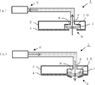
- (A) It is side surface sectional drawing which showed an example of the workpiece holding apparatus of this invention.
- (B) It is the top view which showed an example of the workpiece holding apparatus of this invention. It is the schematic which showed an example of the aspect at the time of workpiece
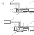
- (A) It is side surface sectional drawing which showed an example of the workpiece holding apparatus of this invention at the time of workpiece
- (B) It is side surface sectional drawing which showed an example of the workpiece holding apparatus of this invention at the time of workpiece
- FIG. 3 is a diagram illustrating an outline of an experiment performed in Example 1. It is a figure explaining the adsorption
- A It is side surface sectional drawing which showed an example of the conventional common workpiece holding apparatus.
- B It is the top view which showed an example of the conventional common workpiece holding apparatus.
- the present invention is not limited to this.
- a suction force is generated between the workpiece and the suction pad due to the liquid present on the surface.
- the workpiece is detached from the suction pad at an accurate position. There was a problem that I could not.
- the present inventors first considered the characteristics of the adsorptive power by the liquid as follows. As shown in FIG. 9, it is known that a liquid 153 interposed between two parallel flat plates 151 and 152 generates an adsorption force F expressed by the following equation.
- the cosine of the liquid area A, the liquid viscosity ⁇ , and the contact angle ⁇ of the liquid on the plane should be reduced, and the thickness h of the intervening liquid should be increased.
- the viscosity of the liquid and the liquid used are the requirements in the processing process or the result of the processing, it is desirable to avoid changing these parameters from the viewpoint of the conveyance to assist the wafer processing. Therefore, the present inventors paid attention to the area and thickness of the intervening liquid.
- the contact angle between the liquid and the suction pad As a method of increasing the thickness of the intervening liquid, it is conceivable to increase the contact angle between the liquid and the suction pad. As described above, the liquid itself is often selected for processing reasons, and it is not desirable to change it from the viewpoint of conveyance. In order to increase the contact angle without changing the liquid, it is conceivable to increase the water repellency of the suction pad. When the suction pad is new, the contact angle can be increased because of high water repellency.
- a slurry containing a large amount of wetting agent is generally supplied at the end of polishing. Such a wetting agent increases the wettability with the use time even for a highly water-repellent adsorption pad, and it is difficult to maintain a large contact angle over the entire life of the adsorption pad.
- the present inventors can increase the distance between the workpiece and the suction pad (the thickness h of the intervening liquid) if at least a part of the contact surface of the suction pad with the workpiece is expanded toward the workpiece when the workpiece is detached.
- the present invention has been completed by conceiving that the area A can be reduced by forcibly increasing the size and moving the liquid.
- a work holding device 1 of the present invention includes a rigid body 2 that is an apparatus main body, an elastic suction pad 4 bonded to the lower end surface of the rigid body 2, and air that can suck and discharge air. It consists of a control mechanism 6 and the like.
- the rigid body 2 has a ventilation hole 3 formed therein, and the ventilation hole 3 communicates with the air control mechanism 6. Further, the suction pad 4 is provided with an opening 5 penetrating from the upper surface to the lower surface. In the case of FIG. 1, the opening 5 is connected to the vent hole 3 through a space portion 8. As described above, the opening 5 can suck and discharge air from the air control mechanism 6 and can suck and discharge air from the opening 5.
- the suction pad 4 is sucked by the air control mechanism 6 while holding the workpiece W. Is brought into contact with the workpiece W to suck and hold the workpiece W. Then, the workpiece holding device 1 holding the workpiece W is moved to a target position by a robot, an actuator, or the like (not shown). Thereafter, the workpiece W is detached (detached) from the workpiece holding device 1 to complete the conveyance of the workpiece W to the target position.
- the concave portion 7 formed in the lower end portion of the rigid body 2, the suction pad 4, and the space portion defined by both of them. 8 may be provided.
- the suction pad 4 covering the space 8 is provided with an opening 5 for securing an air passage.
- the opening 5 is smaller than the space 8.
- the work holding device of the present invention even when the work on which the liquid remains on the surface is detached, the adsorption force by the liquid can be greatly reduced, and the work can be detached.
- the present invention can of course be used when removing and attaching a dry workpiece with no liquid remaining on the surface. By pushing the workpiece downward with the bulge, the removal and removal of the workpiece can be promoted more effectively than before. can do. If the work holding device of the present invention is attached to a robot, an actuator, or the like when transporting a work, the work can be reliably transported to a target position, and damage to the wafer or apparatus due to unintentional dropping of the wafer can be prevented. Therefore, it is possible to prevent a decrease in yield and a decrease in productivity.
- the bulging portion 9 presses the suction pad 4 by being pressed by the air discharged from the air control mechanism 6 into the space portion 8, and the pressing member 10 that expands the suction pad 4. It is preferable that it has.
- the pressing member 10 can have the same thickness as the depth of the concave portion 7 of the rigid body 2, for example, and can have a hole having a smaller width than the vent hole 3 for allowing air to pass through the central portion thereof. . With such a structure, the surface shape of the suction pad 4 is not deformed when the workpiece is sucked ((a) in FIG. 3), but when the workpiece is detached, the pressing member 10 is pressed by air so that the suction pad 4 is removed. The suction pad 4 can be pressed and inflated ((b) of FIG. 3).
- the suction pad can be reliably swelled by the pressing member if the bulging portion has the pressing member in the space portion, the work can be more reliably detached from the suction pad.
- the bulging portion 9 is provided in the opening 5 of the suction pad 4 is shown, but the bulging portion 9 may be separately provided in a place other than the opening 5. That is, the bulge portion can be located on the contact surface with the workpiece W other than the opening 5 of the suction pad 4.
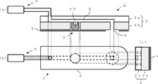
- FIG. 4A it is assumed that the vent hole 3 in the rigid body 2 communicates with each of the opening 5 and the bulging portion 9 and is located at a position other than the opening 5 of the suction pad 4.
- a bulging portion 9 is provided separately. If this is the case, as shown in FIG. 4B, the surface of the suction pad 4 at a position different from the opening 5 due to the air discharged from the air control mechanism 6 when the workpiece is detached. Bulges outward.
- the pressing member 10 can be provided in the space 8.
- the amount of reduction in the suction force due to the liquid interposed between the workpiece and the suction pad increases as the bulge amount of the bulge portion increases.
- the amount of swelling can be controlled by changing the air supply pressure when the swelling portion is inflated, the area of the swelling portion, and the material and thickness of the suction pad. If the combination of these parameters is optimized according to the use environment, a desired bulge amount can be obtained.
- the detachment of the workpiece can be optimized by appropriately setting the formation position of the bulging portion according to the shape of the workpiece to be held.
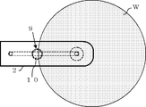
- Example 1 First, as shown in FIGS. 5A, 5 ⁇ / b> B, and 5 ⁇ / b> C, the bulging portion 9 is located on the contact surface with the workpiece W other than the opening 5 of the suction pad 4. A holding device was manufactured.
- the work holding device was manufactured as follows. As shown in FIG. 5, the rigid body 2 serving as the main body of the work holding device 1 employs an overlapping structure of a PVC plate 2a (polyvinyl chloride plate) having a thickness of 3 mm and a stainless plate 2b having a thickness of 5 mm. Then, a part of the air vent 3 which is a passage for air was formed by providing a groove having a width of 6 mm and a depth of 1.5 mm on the overlapping surface of the PVC plate 2a with the stainless steel plate 2b. Further, a hole having a diameter of 6 mm was provided in the rigid body 2 as a part of the air hole 3 on the stainless steel plate 2b side for wafer adsorption.
- a PVC plate 2a polyvinyl chloride plate
- the swelling portion 9 of the suction pad was formed by punching a hole with a diameter of 15 mm in the stainless steel plate 2b, and a pressing member 10 having the same depth as this hole and a diameter of 0.1 mm was mounted in this hole.
- the pressing member 10 was made of the same material as the suction pad 4.
- a backing pad (R601 made by Nitta Haas) having a thickness of 0.5 mm was attached to the lower end surface of the rigid body 2 as a suction pad 4 with a double-sided tape.
- the suction pad 4 was formed with an opening 5 having an area of 160 mm 2 in order to ensure a sufficient suction force.
- piping of the air control mechanism 6 was connected to the vent hole 3 from the PVC board 2a side.
- the work holding device 1 was manufactured as described above.
- the wafer W having a diameter of 300 mm was held by the work holding device 1.
- the area where the workpiece holding device 1 and the wafer W are in contact with each other when holding the wafer W is 4050 mm 2, and the bulging portion 9 is disposed so as to overlap the outer periphery of the wafer W as shown in FIG.
- the adsorption pressure during wafer adsorption was 0.1 MPa. This is because the vacuum pressure of the facility using the work holding device 1 is 0.1 MPa, and the pad cut-out size capable of stably adsorbing the wafer at this pressure is 160 mm 2 .
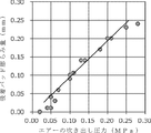
- the blowing pressure of air at the time of wafer removal was set to 0.1 MPa. At this time, the amount of swelling of the swelling portion of the suction pad when the air blowing pressure was changed was measured. The result is shown in FIG.
- the air blowing pressure was set to 0.1 MPa so that sufficient suction force reduction capability was obtained and the swelling amount of the suction pad began to become more stable.
- Increasing the air blowing pressure and increasing the amount of pad deformation is advantageous for reducing the adsorption force.
- the air blowing pressure is set to 0.1 MPa, but of course, the adsorption force can be reduced even when the pressure is 0.1 MPa or less.
- Example 1 Comparative Example 1 As shown in FIG. 10, the experiment and the wafer having a diameter of 300 mm were performed under the same conditions as in Example 1 except that the conventional workpiece holding device was used, that is, the workpiece holding device having no bulge portion of the present invention was used. Was held.
- the conventional work holding device when employed in the automatic handling device attached to the polishing machine, it relates to wafer transfer and storage caused by the suction force caused by the liquid interposed between the suction pad and the wafer. As a result, 13 errors occurred in one month.
- the present invention is not limited to the above embodiment.
- the above-described embodiment is an exemplification, and the present invention has any configuration that has substantially the same configuration as the technical idea described in the claims of the present invention and that exhibits the same effects. Are included in the technical scope.
Landscapes
- Engineering & Computer Science (AREA)
- Mechanical Engineering (AREA)
- Robotics (AREA)
- Container, Conveyance, Adherence, Positioning, Of Wafer (AREA)
- Constituent Portions Of Griding Lathes, Driving, Sensing And Control (AREA)
- Mechanical Treatment Of Semiconductor (AREA)
Abstract
Description
このようなウェーハの搬送において、ロボットやアクチュエータ等に取り付けられたハンド(以下、ワーク保持装置とも称する)がウェーハを保持し、搬送先まで移動し、そこでウェーハをリリースする(特許文献1参照)。この際のウェーハの保持には吸引吸着、エッジグリップ、ベルヌーイチャックといった方式が採用されることが一般的である。
ワーク保持装置101には、エアー制御機構106、通気孔103が設けられ、ワークWを吸着する際にはエアーを引き、ワークWを切り離そうとする(脱着する)ときには、この吸引を止める、あるいは切り離しをさらに促進するためにエアーを供給する。
この吸引吸着を利用するワーク保持装置101では、弾性を有する吸着パッド104がワーク保持部に貼り付けられることが一般的である。この吸着パッド104は開口部105にエアーを吸引してワークWを吸着する。その際に、吸着パッド104によりワークWと保持部との密着性を増すことで吸引効果を高めることができ、さらに保持装置の本体102とワークWが直接接触することによるワークのキズの発生を防止することができる。
従来のワークの保持装置は、このようにウェーハが濡れている際に、搬送先でウェーハの脱着が上手くできないという問題が発生することがある。
このような構造であれば、簡単な構成で吸着パッドを膨らますことができるため、より容易にワークを吸着パッドから脱着することができるものとなる。
このように空間部内に押圧部材を有するものであれば、押圧部材により確実に吸着パッドを膨らますことができるため、ワークを吸着パッドからより確実に脱着することができるものとなる。
本発明では、膨らみ部を吸着パッドの開口部以外の位置に設けたものとすることができ、保持装置の構造がより単純化され、製造コストを抑えることができる。
上記のように、保持するワークの表面が濡れている場合に、表面に存在する液体によりワークと吸着パッドの間に吸着力が発生してしまい、その結果ワークを吸着パッドから正確な位置で脱着できないという問題があった。
図9に示すように平行な2枚の平板151、152間に介在する液体153は、以下の式に記されるような吸着力Fを発生させることが知られている。
F=(πr2×2γcosθ)/h=(2Aγcosθ)/h
(ここで、r:介在する液体円柱の半径、A:介在する液体の面積、γ:介在する液体の粘度、θ:平面と液体の接触角、h:介在する液体円柱の高さ(液体の厚さ)である。)
この式によれば、液体による吸着力は、介在する液体の面積、液体の粘度、および平面上における液体の接触角の余弦に比例し、介在する液体の厚さに反比例する。
ここで液体の粘度、及び使用している液体は、加工プロセス上の要求あるいは、加工の結果であるため、ウェーハ加工を補助する搬送の観点からこれらのパラメータを変更するのは避けるのが望ましい。従って、本発明者等は、介在する液体の面積と厚さに着目した。
シリコンウェーハにおいては、大直径化が進んでおり、安易に接触面積を小さくすると、さらに大直径化が進んだときに、このようなたわみや振動といった問題がさらに顕著に発生する危険性が高い。
また、液体を変更せずに接触角を大きくするためには、吸着パッドの撥水性を高めることが考えられる。吸着パッドが新しい場合には、撥水性が高いため接触角を大きくできる。しかし、例えばシリコンウェーハの研磨プロセスなどでは、研磨後のウェーハ表面を保護するため、研磨終了時に濡れ剤を多く含んだスラリーを供給することが一般的である。このような濡れ剤は、撥水性の高い吸着パッドすら、使用時間に伴い濡れ性を高めてしまい、吸着パッドライフ全般にわたり、大きな接触角を維持するのは難しい。
図1に示すように、本発明のワーク保持装置1は、装置本体である剛性体2、剛性体2の下端面に接着された弾性を有する吸着パッド4、エアーの吸引及び吐出が可能なエアー制御機構6等から構成される。
また、吸着パッド4には、その上面から下面を貫通する開口部5が設けられており、図1の場合、開口部5は空間部8を介して通気孔3に接続されている。このように、開口部5はエアー制御機構6からエアーを吸引及び吐出して、開口部5からエアーを吸引及び吐出することができるものとなっている。
そして、ロボットやアクチュエータ等(不図示)により、ワークWを保持した状態のワーク保持装置1を目的位置まで移動させる。
その後、ワーク保持装置1からワークWを脱着(脱離)させて目的位置へのワークWの搬送を完了する。
この空間部8を覆う吸着パッド4には、エアーの通路を確保するための開口部5が設けられている。そして、この開口部5は空間部8よりも小さいものとなっている。
この構成では、図2に示すように、エアー制御機構6からエアーを吐出すると、吸着パッド4の開口部5が、空間部8より小さいため、空間部8の気圧が高まり、吸着パッド4の開口部5の周辺が膨らむ。図2に示すように、ワークW表面が濡れている場合、この膨らみ部9によりワークWと吸着パッド4の間隔は強制的に広げられ(図2の(1))、その結果、ワークWと吸着パッド4の間に介在する液体は移動して液体の面積Aは減少し(図2の(2))、且つ液体の厚さhは増加する(図2の(3))。
そして、ワークの搬送において、本発明のワーク保持装置をロボットやアクチュエータ等に取り付けて使用すれば、ワークを確実に狙い位置に搬送でき、意図しないウェーハの落下によるウェーハや装置の破損などを防止できるため、歩留まり低下や生産性の低下を防止することができる。
この押圧部材10は、例えば剛性体2の凹部7の深さと同じ厚さとすることができ、その中心部にエアーを通すための、通気孔3より幅が小さい穴を有するものとすることができる。このような構造であれば、ワークの吸着時には、吸着パッド4の表面形状を変形させないが(図3の(a))、脱着時にはこの押圧部材10がエアーにより押圧されることで吸着パッド4を押圧し、吸着パッド4を膨らませることが可能なものとできる(図3の(b))。
例えば、図4の(a)に示すように、剛性体2内の通気孔3を開口部5と膨らみ部9のそれぞれに連通しているものとし、吸着パッド4の開口部5以外の位置に膨らみ部9を別途設ける。
このようなものであれば、図4の(b)に示すように、ワークを脱離させる際に、エアー制御機構6から吐出されたエアーにより、開口部5とは別位置の吸着パッド4表面が外側に膨らむ。
また、この場合も図4に示すように、空間部8に押圧部材10を有するものとすることができる。
まず、図5の(a)、(b)、(c)に示すような、膨らみ部9が、吸着パッド4の開口部5以外のワークWとの接触面に位置する態様の本発明のワーク保持装置を製造した。
図5に示すように、ワーク保持装置1の本体となる剛性体2は、厚さ3mmのPVC板2a(ポリ塩化ビニル板)と厚さ5mmのステンレス板2bとの重ね合わせ構造を採用した。そして、PVC板2aのステンレス板2bとの重ね合せ面に幅6mm、深さ1.5mmの溝を設けることによりエアーの通り路である通気孔3の一部を形成した。また、ウェーハ吸着のため、剛性体2には直径6mmの穴を通気孔3の一部としてステンレス板2b側に設けた。また、吸着パッドの膨らみ部9は、ステンレス板2bに直径15mmで穴をくり抜き、この穴と同じ深さで、直径が0.1mm小さい押圧部材10をこの穴に装着した。なお、押圧部材10は、吸着パッド4と同じ材質を用いた。
ウェーハ脱着時のエアーの吹き出し圧力は0.1MPaに設定した。このとき、エアー吹き出し圧力を変化させたときの、吸着パッドの膨らみ部の膨らみ量を測定した。その結果を図7に示す。
図8に示すように、直径300mmのウェーハWをテーブル200の上に接着固定した。次に、テーブル200の上に固定されたウェーハWの表面を十分に水で濡らした。次に、本発明のワーク保持装置1をウェーハW表面に押さえつけ、ウェーハ上を濡らした水によりワーク保持装置1をウェーハに吸着させた。この時、真空は用いていないので、吸着する力は吸着パッド4とウェーハW間に介在する水のみによるものであった。次に、吸着したワーク保持装置1にバネばかり300を装着し、ワーク保持装置1に吹き出し圧力0.05MPaでエアーを供給しながら水平方向に引っ張った。そして、ウェーハWに吸着したワーク保持装置1がウェーハ上を動き出すときのバネばかりの読み値から、介在する液体の吸着力を測定した。この実験を繰り返し行い、バネばかりの読み値の平均値を算出したところ、その値は平均5.6gであった。この値は、後述する比較例よりも著しく小さい値であり、本発明であればワーク保持装置がウェーハを脱着する際における、ウェーハが吸着パッドに吸着する力を大幅に低減できることを確認できた。
図10に示すような、従来のワーク保持装置を使用したこと、即ち、本発明の膨らみ部を持たないワーク保持装置を使用したこと以外、実施例1と同様な条件で実験及び直径300mmのウェーハの保持を行った。
その結果、バネばかりの読み値の平均値を算出したところ、その値は平均61gとなり、実施例1の十倍以上の吸着力となっていることが分かった。
Claims (4)
- 通気孔を有する剛性体と、該剛性体の下端面に接着され、前記通気孔に連通した開口部を有する、ワークを吸着し保持するための吸着パッドと、前記通気孔に連通し、前記通気孔からエアーを吸引又は吐出することで前記開口部からエアーを吸引又は吐出するエアー制御機構とを具備し、前記開口部に前記ワークを接触させながら、前記エアー制御機構でエアーを吸引して前記開口部からエアーを吸引することで前記吸着パッドに前記ワークを吸着して保持し、前記エアー制御機構からエアーを吐出して前記開口部からエアーを吐出することで前記吸着パッドから前記ワークを脱着するワーク保持装置であって、
前記吸着パッドから前記ワークを脱着する際に、前記エアー制御機構により前記通気孔からエアーが供給されることで、前記吸着パッドの前記ワークとの接触面の少なくとも一部が前記ワーク側に膨らむ膨らみ部を有するものであることを特徴とするワーク保持装置。 - 前記膨らみ部は、前記剛性体の下端部に形成された凹部と、前記吸着パッドと、この両者により区画された空間部から成り、前記エアー制御機構により、前記空間部にエアーが供給されて加圧されることで前記吸着パッドが前記ワーク側に膨らむものであることを特徴とする請求項1に記載のワーク保持装置。
- 前記膨らみ部は、前記空間部に、前記エアー制御機構から吐出されるエアーにより押圧されることによって前記吸着パッドを押圧し、前記吸着パッドを膨らませる押圧部材を有するものであることを特徴とする請求項2に記載のワーク保持装置。
- 前記膨らみ部は、前記吸着パッドの前記開口部以外の前記ワークとの接触面に位置するものであることを特徴とする請求項1から請求項3のいずれか1項に記載のワーク保持装置。
Priority Applications (5)
| Application Number | Priority Date | Filing Date | Title |
|---|---|---|---|
| DE112015000945.0T DE112015000945B4 (de) | 2014-03-19 | 2015-02-17 | Werkstückhaltegerät |
| US15/122,524 US9728442B2 (en) | 2014-03-19 | 2015-02-17 | Workpiece holding apparatus |
| KR1020167024586A KR102136134B1 (ko) | 2014-03-19 | 2015-02-17 | 워크유지장치 |
| SG11201607263VA SG11201607263VA (en) | 2014-03-19 | 2015-02-17 | Workpiece holding apparatus |
| CN201580011905.1A CN106068555B (zh) | 2014-03-19 | 2015-02-17 | 工件支承装置 |
Applications Claiming Priority (2)
| Application Number | Priority Date | Filing Date | Title |
|---|---|---|---|
| JP2014-056852 | 2014-03-19 | ||
| JP2014056852A JP6032234B2 (ja) | 2014-03-19 | 2014-03-19 | ワーク保持装置 |
Publications (1)
| Publication Number | Publication Date |
|---|---|
| WO2015141122A1 true WO2015141122A1 (ja) | 2015-09-24 |
Family
ID=54144114
Family Applications (1)
| Application Number | Title | Priority Date | Filing Date |
|---|---|---|---|
| PCT/JP2015/000703 Ceased WO2015141122A1 (ja) | 2014-03-19 | 2015-02-17 | ワーク保持装置 |
Country Status (8)
| Country | Link |
|---|---|
| US (1) | US9728442B2 (ja) |
| JP (1) | JP6032234B2 (ja) |
| KR (1) | KR102136134B1 (ja) |
| CN (1) | CN106068555B (ja) |
| DE (1) | DE112015000945B4 (ja) |
| SG (1) | SG11201607263VA (ja) |
| TW (1) | TWI613750B (ja) |
| WO (1) | WO2015141122A1 (ja) |
Families Citing this family (6)
| Publication number | Priority date | Publication date | Assignee | Title |
|---|---|---|---|---|
| DE102014212176A1 (de) * | 2014-06-25 | 2015-12-31 | Siemens Aktiengesellschaft | Pulverbettbasiertes additives Fertigungsverfahren und Anlage zur Durchführung dieses Verfahrens |
| JP6822869B2 (ja) * | 2017-02-21 | 2021-01-27 | 株式会社ディスコ | 剥離装置 |
| US10724572B2 (en) | 2017-08-23 | 2020-07-28 | Todd H. Becker | Electronically-releasable suction cup assembly secured to an appliance |
| CN107871703A (zh) * | 2017-10-27 | 2018-04-03 | 德淮半导体有限公司 | 晶圆加工装置及其加工方法 |
| CN109037109A (zh) * | 2018-08-03 | 2018-12-18 | 德淮半导体有限公司 | 一种半导体设备及清洗晶圆的方法 |
| JP7352168B2 (ja) * | 2019-11-06 | 2023-09-28 | 三益半導体工業株式会社 | 搬送ヘッドおよび搬送装置 |
Citations (3)
| Publication number | Priority date | Publication date | Assignee | Title |
|---|---|---|---|---|
| US4669915A (en) * | 1985-11-19 | 1987-06-02 | Shell Offshore Inc. | Manipulator apparatus with flexible membrane for gripping submerged objects |
| JP2005123485A (ja) * | 2003-10-17 | 2005-05-12 | Ebara Corp | 研磨装置 |
| JP2012204709A (ja) * | 2011-03-28 | 2012-10-22 | Okamoto Machine Tool Works Ltd | 半導体基板保持用のパッドおよびそれを用いて半導体基板を搬送する方法 |
Family Cites Families (18)
| Publication number | Priority date | Publication date | Assignee | Title |
|---|---|---|---|---|
| US3602543A (en) * | 1968-12-18 | 1971-08-31 | Munck Int As | Arrangement in suction cup for vacuum lifting |
| FR2431635A1 (fr) * | 1978-07-20 | 1980-02-15 | Sgn Soc Gen Tech Nouvelle | Dispositif de prehension par ventouse |
| US4221356A (en) * | 1978-11-09 | 1980-09-09 | Fortune William S | Vacuum operated holding fixture |
| JPS5864038A (ja) * | 1981-10-13 | 1983-04-16 | Nec Corp | ボンデイングプレ−ト |
| US4620738A (en) * | 1985-08-19 | 1986-11-04 | Varian Associates, Inc. | Vacuum pick for semiconductor wafers |
| US5423716A (en) * | 1994-01-05 | 1995-06-13 | Strasbaugh; Alan | Wafer-handling apparatus having a resilient membrane which holds wafer when a vacuum is applied |
| US5685513A (en) * | 1995-05-17 | 1997-11-11 | Nihon Biso Co., Ltd. | Vacuum-suction attachment pad |
| JP3027551B2 (ja) * | 1997-07-03 | 2000-04-04 | キヤノン株式会社 | 基板保持装置ならびに該基板保持装置を用いた研磨方法および研磨装置 |
| JP3398094B2 (ja) | 1999-07-16 | 2003-04-21 | 株式会社リブドゥコーポレーション | 使い捨てパンツ |
| KR100939096B1 (ko) * | 2001-05-29 | 2010-01-28 | 가부시키가이샤 에바라 세이사꾸쇼 | 폴리싱장치, 폴리싱방법 및 기판캐리어 시스템 |
| WO2004096679A1 (ja) * | 2003-04-30 | 2004-11-11 | Olympus Corporation | 基板浮上装置 |
| NL1024965C2 (nl) * | 2003-12-08 | 2005-06-09 | Goudsmit Magnetic Systems B V | Grijpmiddelen en hefinrichting voor het vastpakken en optillen van een voorwerp, in het bijzonder een plaat. |
| DE102006031434B4 (de) * | 2006-07-07 | 2019-11-14 | Erich Thallner | Handhabungsvorrichtung sowie Handhabungsverfahren für Wafer |
| JP5379589B2 (ja) | 2009-07-24 | 2013-12-25 | 東京エレクトロン株式会社 | 真空吸着パッド、搬送アーム及び基板搬送装置 |
| US9650726B2 (en) * | 2010-02-26 | 2017-05-16 | Applied Materials, Inc. | Methods and apparatus for deposition processes |
| US9108319B2 (en) * | 2011-02-01 | 2015-08-18 | Delaware Capital Formation, Inc. | Electric suction cup |
| JP5692106B2 (ja) * | 2012-02-01 | 2015-04-01 | 東京エレクトロン株式会社 | 周縁露光装置、周縁露光方法及び記憶媒体 |
| CN202643070U (zh) | 2012-05-25 | 2013-01-02 | 绍兴县力锐家具制造有限公司 | 一种真空吸盘装置 |
-
2014
- 2014-03-19 JP JP2014056852A patent/JP6032234B2/ja active Active
-
2015
- 2015-02-17 KR KR1020167024586A patent/KR102136134B1/ko active Active
- 2015-02-17 CN CN201580011905.1A patent/CN106068555B/zh active Active
- 2015-02-17 US US15/122,524 patent/US9728442B2/en active Active
- 2015-02-17 SG SG11201607263VA patent/SG11201607263VA/en unknown
- 2015-02-17 DE DE112015000945.0T patent/DE112015000945B4/de active Active
- 2015-02-17 WO PCT/JP2015/000703 patent/WO2015141122A1/ja not_active Ceased
- 2015-02-25 TW TW104105975A patent/TWI613750B/zh active
Patent Citations (3)
| Publication number | Priority date | Publication date | Assignee | Title |
|---|---|---|---|---|
| US4669915A (en) * | 1985-11-19 | 1987-06-02 | Shell Offshore Inc. | Manipulator apparatus with flexible membrane for gripping submerged objects |
| JP2005123485A (ja) * | 2003-10-17 | 2005-05-12 | Ebara Corp | 研磨装置 |
| JP2012204709A (ja) * | 2011-03-28 | 2012-10-22 | Okamoto Machine Tool Works Ltd | 半導体基板保持用のパッドおよびそれを用いて半導体基板を搬送する方法 |
Also Published As
| Publication number | Publication date |
|---|---|
| SG11201607263VA (en) | 2016-10-28 |
| JP2015179754A (ja) | 2015-10-08 |
| DE112015000945T5 (de) | 2017-01-05 |
| DE112015000945B4 (de) | 2022-07-28 |
| KR102136134B1 (ko) | 2020-07-22 |
| TWI613750B (zh) | 2018-02-01 |
| JP6032234B2 (ja) | 2016-11-24 |
| CN106068555B (zh) | 2018-11-20 |
| KR20160134665A (ko) | 2016-11-23 |
| TW201540629A (zh) | 2015-11-01 |
| US20170069523A1 (en) | 2017-03-09 |
| US9728442B2 (en) | 2017-08-08 |
| CN106068555A (zh) | 2016-11-02 |
Similar Documents
| Publication | Publication Date | Title |
|---|---|---|
| JP6032234B2 (ja) | ワーク保持装置 | |
| TWI512877B (zh) | 工件搬運方法及工件搬運裝置 | |
| JP2015076570A (ja) | 剥離装置、剥離システム、剥離方法、プログラム及びコンピュータ記憶媒体 | |
| CN102683256A (zh) | 制造半导体装置的设备和方法 | |
| JP2010135436A (ja) | 基板への接着テープ貼り付け装置 | |
| CN102201327A (zh) | 粘合带粘贴方法及粘合带粘贴装置 | |
| JP6309371B2 (ja) | 板状ワークの搬出方法 | |
| JP5914062B2 (ja) | 板状ワークの保持解除方法及び加工装置 | |
| JP6318033B2 (ja) | 研削装置及び保護テープ貼着方法 | |
| JP2010118424A (ja) | 薄板状ワークの搬送装置 | |
| CN110364417A (zh) | 粘合带剥离方法和粘合带剥离装置 | |
| JP7214455B2 (ja) | 保護部材形成装置 | |
| WO2013058094A1 (ja) | ワーク保持装置 | |
| JP2018186194A (ja) | 基板の離脱方法および基板の離脱装置 | |
| JP2014083622A (ja) | バキュームパッド装置及び吸着搬送方法 | |
| KR20160046732A (ko) | 점착 테이프 부착 방법 및 점착 테이프 부착 장치 | |
| JP2015118719A (ja) | ガラス基板分離装置、ガラス基板分離方法及びガラス基板の製造方法 | |
| CN117425606A (zh) | 吸附式抓持装置以及柔性平坦的基板的拾取及存放方法 | |
| JP2009066719A (ja) | 基板吸着搬送装置 | |
| JP2014176914A (ja) | 吸着パッド及び吸着装置 | |
| JP2014175541A (ja) | ウェーハ貼着方法 | |
| JP5329916B2 (ja) | 半導体ウエハの支持具 | |
| JP4002444B2 (ja) | 偏光板供給装置 | |
| JP2010182918A (ja) | 化学機械研磨機用のバッキングフィルム | |
| JP7494913B2 (ja) | 吸着パッド |
Legal Events
| Date | Code | Title | Description |
|---|---|---|---|
| 121 | Ep: the epo has been informed by wipo that ep was designated in this application |
Ref document number: 15765067 Country of ref document: EP Kind code of ref document: A1 |
|
| WWE | Wipo information: entry into national phase |
Ref document number: 15122524 Country of ref document: US |
|
| ENP | Entry into the national phase |
Ref document number: 20167024586 Country of ref document: KR Kind code of ref document: A |
|
| WWE | Wipo information: entry into national phase |
Ref document number: 112015000945 Country of ref document: DE |
|
| 122 | Ep: pct application non-entry in european phase |
Ref document number: 15765067 Country of ref document: EP Kind code of ref document: A1 |