WO2015137348A1 - 還元鉄の製造方法及び製造設備 - Google Patents
還元鉄の製造方法及び製造設備 Download PDFInfo
- Publication number
- WO2015137348A1 WO2015137348A1 PCT/JP2015/057034 JP2015057034W WO2015137348A1 WO 2015137348 A1 WO2015137348 A1 WO 2015137348A1 JP 2015057034 W JP2015057034 W JP 2015057034W WO 2015137348 A1 WO2015137348 A1 WO 2015137348A1
- Authority
- WO
- WIPO (PCT)
- Prior art keywords
- reduction
- furnace
- product
- reducing
- reduced iron
- Prior art date
- Legal status (The legal status is an assumption and is not a legal conclusion. Google has not performed a legal analysis and makes no representation as to the accuracy of the status listed.)
- Ceased
Links
Images


Classifications
-
- C—CHEMISTRY; METALLURGY
- C21—METALLURGY OF IRON
- C21B—MANUFACTURE OF IRON OR STEEL
- C21B13/00—Making spongy iron or liquid steel, by direct processes
- C21B13/14—Multi-stage processes processes carried out in different vessels or furnaces
-
- C—CHEMISTRY; METALLURGY
- C21—METALLURGY OF IRON
- C21B—MANUFACTURE OF IRON OR STEEL
- C21B13/00—Making spongy iron or liquid steel, by direct processes
- C21B13/0073—Selection or treatment of the reducing gases
-
- C—CHEMISTRY; METALLURGY
- C21—METALLURGY OF IRON
- C21B—MANUFACTURE OF IRON OR STEEL
- C21B13/00—Making spongy iron or liquid steel, by direct processes
- C21B13/02—Making spongy iron or liquid steel, by direct processes in shaft furnaces
-
- C—CHEMISTRY; METALLURGY
- C21—METALLURGY OF IRON
- C21B—MANUFACTURE OF IRON OR STEEL
- C21B13/00—Making spongy iron or liquid steel, by direct processes
- C21B13/10—Making spongy iron or liquid steel, by direct processes in hearth-type furnaces
- C21B13/105—Rotary hearth-type furnaces
-
- F—MECHANICAL ENGINEERING; LIGHTING; HEATING; WEAPONS; BLASTING
- F27—FURNACES; KILNS; OVENS; RETORTS
- F27B—FURNACES, KILNS, OVENS OR RETORTS IN GENERAL; OPEN SINTERING OR LIKE APPARATUS
- F27B1/00—Shaft or like vertical or substantially vertical furnaces
- F27B1/10—Details, accessories or equipment specially adapted for furnaces of these types
-
- C—CHEMISTRY; METALLURGY
- C21—METALLURGY OF IRON
- C21B—MANUFACTURE OF IRON OR STEEL
- C21B13/00—Making spongy iron or liquid steel, by direct processes
- C21B13/08—Making spongy iron or liquid steel, by direct processes in rotary furnaces
- C21B13/085—Making spongy iron or liquid steel, by direct processes in rotary furnaces wherein iron or steel is obtained in a molten state
-
- C—CHEMISTRY; METALLURGY
- C21—METALLURGY OF IRON
- C21B—MANUFACTURE OF IRON OR STEEL
- C21B2300/00—Process aspects
- C21B2300/02—Particular sequence of the process steps
-
- F—MECHANICAL ENGINEERING; LIGHTING; HEATING; WEAPONS; BLASTING
- F27—FURNACES; KILNS; OVENS; RETORTS
- F27B—FURNACES, KILNS, OVENS OR RETORTS IN GENERAL; OPEN SINTERING OR LIKE APPARATUS
- F27B3/00—Hearth-type furnaces, e.g. of reverberatory type; Electric arc furnaces ; Tank furnaces
- F27B3/10—Details, accessories or equipment, e.g. dust-collectors, specially adapted for hearth-type furnaces
- F27B3/12—Working chambers or casings; Supports therefor
- F27B2003/125—Hearths
-
- F—MECHANICAL ENGINEERING; LIGHTING; HEATING; WEAPONS; BLASTING
- F27—FURNACES; KILNS; OVENS; RETORTS
- F27M—INDEXING SCHEME RELATING TO ASPECTS OF THE CHARGES OR FURNACES, KILNS, OVENS OR RETORTS
- F27M2003/00—Type of treatment of the charge
- F27M2003/16—Treatment involving a chemical reaction
- F27M2003/165—Reduction
-
- Y—GENERAL TAGGING OF NEW TECHNOLOGICAL DEVELOPMENTS; GENERAL TAGGING OF CROSS-SECTIONAL TECHNOLOGIES SPANNING OVER SEVERAL SECTIONS OF THE IPC; TECHNICAL SUBJECTS COVERED BY FORMER USPC CROSS-REFERENCE ART COLLECTIONS [XRACs] AND DIGESTS
- Y02—TECHNOLOGIES OR APPLICATIONS FOR MITIGATION OR ADAPTATION AGAINST CLIMATE CHANGE
- Y02P—CLIMATE CHANGE MITIGATION TECHNOLOGIES IN THE PRODUCTION OR PROCESSING OF GOODS
- Y02P10/00—Technologies related to metal processing
- Y02P10/20—Recycling
Definitions
- the present invention relates to a method and equipment for producing reduced iron.
- the present invention relates to a reduced iron production method and production facility capable of stably obtaining reduced iron having a high metallization rate stably regardless of fluctuations in raw material properties.
- Powdered iron oxides such as dust (iron blast furnace dust, converter dust, etc., hereinafter sometimes referred to as high quality dust) and iron oxide ores, etc. containing iron oxide generated in the steelmaking and steelmaking processes in recent years
- a method of producing reduced iron using a raw material hereinafter sometimes referred to as a high quality powdered iron oxide raw material is widely used.
- a powdered iron oxide raw material such as iron dust or iron ore and a carbonaceous reducing material are mixed and subjected to agglomeration treatment to form pellets or briquette agglomerates
- a method for example, Patent Document 1 in which this agglomerate is heated and reduced in a reduction furnace such as a rotary hearth furnace in which the hearth moves continuously, or a powdered iron oxide raw material and a carbonaceous reducing material are used.
- a reduction furnace such as a rotary hearth furnace in which the hearth moves continuously
- a powdered iron oxide raw material and a carbonaceous reducing material are used.
- the technique for example, patent document 2 which heats and reduces with a rotary kiln is known.
- such inferior powdered iron oxide raw material has a higher degree of raw material oxidation than high quality dust, so when used as a raw material for the production of reduced iron, the metallization rate of product reduced iron (product metallization rate) is reduced.
- the raw material oxidation degree (sometimes simply referred to as “oxidation degree”) is the theoretical oxygen amount that can be combined when all the iron-containing components (metallic iron, wustite, magnetite, hematite) in the raw material become hematite. Is an index defined by the mass percentage of the amount of oxygen actually bound to iron.
- the product metallization rate is an index defined by the mass percentage of metal iron with respect to the total iron content in the product reduced iron. Since the load of finishing and reducing reduced iron in a subsequent process is reduced, a higher product metallization rate is desirable.
- JP 2003-293020 A Japanese Patent Laid-Open No. 2001-280849 JP 2000-160219 A JP 2012-126963 A JP 2010-222667 A JP 59-25910 A
- the production capacity of reduced iron that is, the amount of iron oxide in the raw material reduced in the furnace per unit time is mainly the furnace of the rotary hearth. Determined by floor area and furnace temperature. In actual operation, in order to maximize production efficiency, it is general to operate with the furnace temperature as high as possible within the scope of equipment constraints.
- the productivity of reduced iron is decreasing with an increase in the amount of inferior powdered iron oxide raw material used.
- the inferior powder iron oxide raw material not only has a high degree of oxidation, but also has a large variation in raw material properties within the same brand.
- the residence time of the agglomerate in the rotary hearth furnace during the production of reduced iron is as short as about 15 to 25 minutes, and it is also very practical in practice to change the reduction time following the variation in raw material properties. It is difficult to.
- the reduction reaction of powdered iron oxide agglomerates with carbonaceous materials as the reducing material proceeds by reducing the iron oxides such as hematite, magnetite, and wustite with carbon monoxide present in the pores of the agglomerates. To do.
- the agglomerate of reduced iron production raw material is generally a porous body having a porosity of 30% or more, and its apparent thermal conductivity is smaller than a value predicted from the component average.
- the conduction heat transfer in the agglomerates is very slow.
- Patent Document 3 discloses a technique for defining the properties of carbonaceous materials and ores in order to improve the internal heat transfer rate of iron ore agglomerates with carbonaceous materials.
- Patent Document 4 discloses a method of mixing linear additives that promote heat transfer. However, none of the methods essentially suppresses the increase in porosity due to the oxygen being bound to the iron oxide with the reduction reaction.
- the metallization rate of reduced iron reaches at least about 60% in the final stage of the rotary hearth furnace, and at the same time the porosity Is also getting bigger. That is, at the time of the final stage of the rotary hearth furnace, the thermal conductivity of the reduced iron has already been sufficiently reduced, and the rotary hearth furnace has only a radiant heat transfer mechanism for supplying heat to the agglomerates, When finishing reduction of reduced iron is attempted, it is easily predicted that the facility will be very large.
- Patent Documents 5 and 6 describe techniques for proceeding the reduction reaction by taking two steps without expanding one reduction furnace.
- hematite or goethite is previously reduced to magnetite with a reducing gas using a fluidized bed reactor, and then a microwave is added to a mixture obtained by adding a carbonaceous reducing material to the obtained semi-reduced product.
- the method of further reducing and obtaining metallic iron by irradiating and heating is described.
- Patent Document 6 proposes a technique for increasing the carbon monoxide content in the exhaust gas and accelerating the preliminary reduction when the exhaust gas from the rotary kiln that is a reduction furnace is used for preheating and preliminary reduction of the raw material. This is aimed at improving the reduction efficiency in the rotary kiln.
- this technology is premised on reduction in a rotary kiln, and the exhaust gas temperature of the rotary kiln is lower than the temperature in the furnace, so the effect of the preliminary reduction that can be achieved using this exhaust gas is the reduction furnace itself. It is easily guessed that it is smaller than the two-stage.
- inferior powdered iron oxide raw material since the use of inferior powdered iron oxide raw material is not premised on the technical level at that time, this technology cannot be applied to the inferior powdered iron oxide raw material as it is.
- To apply an inferior powdered iron oxide raw material it is better to use a rotary hearth type reducing furnace with good reduction efficiency, but it has better thermal efficiency and reduction efficiency. The problem of deterioration remains.
- the present invention remodels an existing rotary hearth furnace on a large scale even when using a raw material with a large variation in properties or an inferior powdered iron oxide raw material with a high degree of oxidation. It is an object of the present invention to provide a reduced iron with a high metalization rate stably only by adding inexpensive and easy finishing reduction equipment, and to provide a reduced iron production method and production equipment that solve the problem For the purpose.
- the present inventors diligently studied a method for solving the above problems. As a result, the following knowledge was obtained.
- first stage reduction hereinafter referred to as first reduction, and the reduction furnace at this time is referred to as the first reduction furnace.
- the obtained reduction product (the reduction product obtained in the first reduction is referred to as the first reduction product) has a high porosity, the heat conductivity is poor as it is. Therefore, if the second stage of reduction is performed by a method that can utilize the increase in porosity to promote the reduction reaction, reduced iron having a high metallization rate can be stably produced with high efficiency. I found.
- the rotary hearth type reduction furnace (RHF) is applied to the first reduction, and the second reduction (hereinafter referred to as the second reduction)
- the reduction furnace at this time is referred to as a second reduction furnace.
- the first reduction product has a high porosity, and it is easy to diffuse the reduction gas in the furnace through the pores, so that the reducibility is improved. It was found that reduced iron with high thermal efficiency and high metallization rate can be produced by applying a rotary kiln or shaft furnace.
- reducing gas penetrates into the inside of the pores of the first reduction product and reduces iron oxide.
- the inventors have found that the first reduction product can be efficiently reduced by setting the concentration of CO gas in the reducing atmosphere in the second reduction to 10 vol% or more and 85 vol% or less.
- the first reduction product also contains reduced iron with a low metalization rate.
- reduced iron with a low metallization rate has low strength and is pulverized when discharged from the first reduction furnace. Even if a high metallization rate is obtained in the second reduction furnace, the particle size of the reduced iron is reduced as a result of pulverization, and there is a concern of dust generation and reoxidation during handling in the subsequent process.
- reduced iron with a high metalization rate is difficult to powder because of its high strength. Therefore, it has been found that if only the powdered product of the first reduction product is reduced in the second reduction furnace to which the rotary kiln is applied, the reduced iron that has been granulated can be produced while promoting the reduction reaction.
- the progress of the second reduction is hindered if there is too much powdered material.
- the rotary kiln type reduction furnace is applied as the second reduction furnace, the inventors use the rotary kiln type reduction furnace for the second reduction as long as the reduction product contains 75% or less of a reduction product having a particle size of less than 3 mm. Was confirmed to be sufficiently advanced.
- the present invention has been made based on the above findings, and the gist thereof is as follows.
- a method for producing reduced iron in which an agglomerate obtained by mixing an agglomerated iron oxide-containing raw material and a reducing material is subjected to continuous two-stage reduction treatment, (I) applying a rotary hearth type reducing furnace to the first reduction treatment; (Ii) A rotary kiln type or shaft type reduction furnace is applied to the second reduction treatment, and in the second reduction treatment, the concentration of CO gas in the reducing atmosphere is 10% by volume or more and 85% by volume or less.
- a method for producing reduced iron is based on the above findings, and the gist thereof is as follows.
- the method for producing reduced iron according to any one of (1) to (3) above, wherein (5)
- the iron oxide-containing raw material contains at least any one of melting furnace dust, electric furnace dust, rolling scale, pickling / neutralized sludge, (1) to (4), Method for producing reduced iron.
- a reduced iron production facility for reducing agglomerated raw material agglomerated by mixing a raw material containing iron oxide and a reducing material using two continuous reduction furnaces, (A) A rotary hearth type reduction furnace as a first reduction furnace for reducing the raw material agglomerates, (B) A reduction comprising a rotary kiln type or shaft type reduction furnace as a second reduction furnace for further reducing the first reduction product, which is a reduction product generated in the first reduction furnace.
- Iron production equipment for reducing agglomerated raw material agglomerated by mixing a raw material containing iron oxide and a reducing material using two continuous reduction furnaces.
- the present invention it is possible to easily produce a high metal from an inferior powdered iron oxide raw material without using a rotary hearth type reducing furnace having a large equipment scale and without increasing the furnace temperature in order to increase the reaction rate. Reduced iron can be produced. As a result, capital investment for a large rotary hearth type reduction furnace can be avoided.
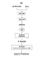
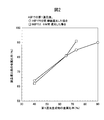
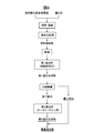
- Example 1 is a conceptual diagram illustrating one embodiment of the present invention. It is a figure which shows the experimental result of Example 1. It is a figure which shows the experimental result of Example 2. It is a conceptual diagram which shows the one aspect
- the method for producing reduced iron according to the present invention comprises agglomerating agglomerated by mixing an iron oxide-containing raw material and a reducing material into a two-stage reduction furnace.
- a method for producing reduced iron that is reduced using (I) A rotary hearth type reducing furnace is used as the first reducing furnace, and then (Ii) A rotary kiln type or shaft type reduction furnace is used as the second reduction furnace, and in the second reduction treatment, the concentration of CO gas in the reducing atmosphere is 10% by volume or more and 85% by volume or less.
- the reduced iron production facility of the present invention (hereinafter sometimes referred to as “the present invention production facility”) comprises agglomerates obtained by mixing agglomerated iron oxide-containing raw material and a reducing material into a two-stage reduction furnace.
- a facility for producing reduced iron that is reduced using (A) a first-stage rotary hearth reducing furnace that receives and reduces the agglomerates; (B) a second stage rotary kiln type or shaft type installed after the rotary hearth type reducing furnace, receiving reduced iron discharged from the rotary hearth type reducing furnace, and further reducing the reduced iron A reduction furnace is provided.
- the present invention (the present invention production method and the present invention production facility may be collectively referred to as “the present invention”) will be described.
- the reduction product discharged from the first reduction furnace is defined as the first reduction product
- the reduction product discharged from the second reduction furnace is defined as the second reduction product.
- the reaction for obtaining the second reduction product from the first reduction product inside the second reduction furnace is referred to as a finishing reduction reaction.
- FIG. 1 shows one embodiment of the present invention in which reduced iron is produced using a two-stage reduction furnace.
- An iron oxide-containing raw material and a reducing material (carbonaceous reducing material) are pulverized and kneaded to give an agglomeration treatment to obtain a raw material agglomerate.
- the raw material agglomerates are dried, they are charged into a first stage rotary hearth type reduction furnace, heated and reduced to produce a first reduction product.
- the first reduction product is charged into a second stage rotary kiln type or shaft type reduction furnace, heated and reduced to produce a second reduction product.
- a rotary kiln-type or shaft-type reduction furnace having a relatively low furnace temperature for additionally heating and reducing the reduced first reduction product is added. Furthermore, in order to accelerate the finish reduction reaction of reduced iron inside the rotary kiln type or shaft type reduction furnace, a reducing gas such as carbon monoxide in the furnace atmosphere is kept at a high concentration.
- the reduction gas originating from the carbon content is supplied from the inside of the agglomerate.
- the influence of the atmosphere outside the agglomerate on the surface is negligibly small. That is, since the pressure of the gas generated from the inside of the agglomerate is higher than the atmospheric pressure, it is difficult for gas to enter from the atmosphere side into the agglomerate.
- the first reduction product discharged from the first reduction furnace which is a rotary hearth type reduction furnace
- the first reduction product discharged from the first reduction furnace which is a rotary hearth type reduction furnace
- the atmospheric gas in the furnace diffuses into the agglomerates through the pores.
- the reduction reaction could proceed efficiently. That is, if the concentration of the reducing gas inside the second reduction furnace that performs the final reduction of the first reduction product is increased, the reducing gas can diffuse into the first reduction product and reduce iron oxide. It was.
- CO (carbon monoxide) gas is a representative example of a reducing gas that is effective in reducing carbonaceous material-containing iron oxide agglomerates. Since the concentration of CO gas in the rotary hearth type reducing furnace during normal operation is less than 10% by volume, the concentration of CO gas in the second reducing furnace is preferably 10% by volume or more. Further, as a result of the study by the present inventors, even if the CO gas concentration is increased too much, the reduction reaction promoting effect is saturated, so the upper limit of the CO gas concentration was set to 85% (FIG. 3).
- a method for increasing the reducing gas concentration in the second reducing furnace a method of injecting a reducing gas from the outside may be used, or the combustion air ratio of the burner burned in the furnace to maintain the furnace temperature is less than 1 and is incomplete.
- a method of burning may be used.
- a method may be used in which a coal-based carbon material is added simultaneously with the first reduction product and decomposed in a furnace to generate a reducing gas.
- the reducing gas required for the iron oxide reduction reaction in the second reduction furnace is supplied directly from the outside of the agglomerate to the inside of the first reduction product. There is no need to cause a Boudowa reaction inside the product, and there is no need to supply the agglomerate with the amount of heat required for the Boudowa reaction. That is, in the finish reduction of the first reduction product having a high porosity, heat transfer rate control can be avoided, and the reduction reaction can be advanced even at a relatively low furnace temperature.
- the atmosphere gas and the first reduction product are strong, which cannot be expected in a rotary hearth type reduction furnace in which an agglomerate is allowed to stand and reduce. Interaction can be obtained. That is, in the case of a rotary kiln type reduction furnace, the first reduction product is agitated by rotating the can body, and in the case of a shaft type reduction furnace, the gas flow and the first reduction product by pushing the gas into the furnace. By this contact, it is possible to promote the diffusion / intrusion of the reducing gas into the pores of the first reduction product. As described above, in the present invention, the high porosity of the first reduction product is effectively utilized for promoting the reduction reaction in the second reduction furnace.
- the porosity of the first reduction product will not be sufficiently large, and the generation pressure of gas from the inside of the pores will be greater than the atmospheric pressure. Cannot diffuse and penetrate into the pores and the reduction reaction does not proceed.
- the desirable lower limit of the metallization rate of the first reduction product was set to 65%. It was confirmed that if the metallization rate was secured to 65% or more, the porosity was sufficiently high and the reduction reaction proceeded in the second reduction (FIG. 2).
- the metallization rate of the first reduction product approaches the target metalization rate of the second reduction product.
- the metallization rate of reduced iron circulated in the market is about 90%.
- the metallization rate of the first reduction product after the completion of the first reduction is 65% or more and 90% or less.
- the second stage rotary kiln reduction furnace When the temperature is 1100 ° C. or lower, the finish reduction reactivity is lowered, so the furnace temperature is preferably higher than 1100 ° C. However, when the furnace temperature of the second stage rotary kiln type reduction furnace exceeds 1200 ° C., kiln rings are remarkably generated. Therefore, the furnace temperature is preferably 1200 ° C. or less.
- inferior powder iron oxide raw materials such as melting furnace dust, electric furnace dust, rolling scale, pickling / neutralized sludge can be applied.
- the first reduction product has a metallization rate of at least about 60% due to the progress of the reduction reaction inside the agglomerate, and the porosity of the first reduction product is accordingly increased.
- the inventors of the present invention efficiently put the first reduction product having a low metallization ratio and a high porosity into the second reduction furnace, and further reduce the efficiency. It has been found that reduced iron with a high metallization rate can be obtained. Further, the present inventors have found that if the second reduction furnace is a rotary kiln type reduction furnace, the atmospheric gas easily penetrates from the pores into the first reduction product, and the final reduction proceeds. Furthermore, the powdered first reduction product is granulated (increase in particle size) in the course of the reduction treatment, and finally, it is found that reduced iron having a high metallization rate and a large particle size can be obtained. It was.
- the properties (component composition, particle size distribution, etc.) of the first reduction product may be properties obtained under normal operating conditions, and are not limited to specific properties. However, if the powdered reduction product having a particle size of less than 3 mm exceeds 75% by mass, the heat transfer rate is controlled in the second stage rotary kiln type reduction furnace, and the effect of atmospheric control that promotes finish reduction can be sufficiently obtained. Absent. Therefore, the first reduction product is preferably 75% by mass or less with a particle size of less than 3 mm.
- the fine-grained portion in the first reduction product does not proceed with the reduction reaction, the metallization rate is low, and the residual carbon is increased.
- the coarse particles in the first reduction product had a sufficiently reduced reaction, a high metallization rate, and a small amount of residual carbon.
- the present inventors classify the first reduction product, finish and reduce only the fine-grained component (pulverized product) with a low metalization rate under the sieve in the second stage rotary kiln type reduction furnace, The idea was to granulate.
- FIG. 4 shows an example of producing reduced iron using a two-stage reduction furnace.
- the process up to the production of the first reduction product in the first stage rotary hearth type reduction furnace is the same as the production mode shown in FIG. However, in the production mode shown in FIG. 4, the first reduction product is classified, and only the unsieved product (low-metallized powder) is charged into the second stage rotary kiln type reduction furnace, and heated and reduced. A second reduction product is obtained.
- the manufacturing facility for manufacturing reduced iron shown in FIG. (A) a first-stage rotary hearth type reduction furnace for heating and reducing a raw material agglomerate obtained by mixing a powdered iron oxide raw material and a carbonaceous reducing material; (B) Classifying equipment installed after the rotary hearth type reduction furnace and classifying the reduction product (first reduction product) discharged from the first stage rotary hearth type reduction furnace; and (C) A second-stage rotary kiln-type reduction furnace that heats and reduces only the reduction product under the sieve is provided.
- the classification facility is a facility for classifying reduction products having a temperature of about 700 to 1100 ° C. discharged from the rotary hearth type reduction furnace, and therefore requires heat resistance.
- a fixed sieve (grizzly) or a water-cooled roller screen is preferable.
- the roller screen is preferable as the classification equipment because the classification particle diameter can be adjusted by changing the distance between the axes.
- the sieved product (coarse particles) has a high metallization rate, it is bypassed without finishing reduction, and in the latter stage, the second reduced product after finishing reduction is combined with the second reduced product to produce product reduced iron.
- the amount of treatment in the second stage rotary kiln type reduction furnace can be reduced, and in addition to downsizing of the rotary kiln type reduction furnace body, the exhaust gas treatment equipment and heating burner of the reduction furnace As a result, it is possible to reduce the size of ancillary facilities such as, and this can lead to a reduction in capital investment.
- the classification reference particle size when classifying the first reduction product is set to the fine particle side, the amount of treatment in the second stage rotary kiln type reduction furnace is reduced, so the scale of the reduction furnace can be reduced.
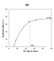
- the mass ratio (hereinafter referred to as “3 mm or less ratio”) of 3 mm or less of the sieved product (pulverized product) processed in the rotary kiln type reduction furnace increases, and the reduction reaction rate in the rotary kiln type reduction furnace. Decreases. As shown in FIG. 5, when the ratio of 3 mm or less exceeds 75%, the finish reduction does not proceed.
- FIG. 6 shows the relationship between the sieving classification ratio (the ratio (% by mass) of the product to be sieved out of the products to be classified) and the final product metallization rate (%). From FIG. 6, it can be seen that if the underclassification ratio is 50% or more, the metallization rate of the final product can be secured 80% or more.
- the conditions in the examples are one example of conditions used for confirming the feasibility and effects of the present invention, and the present invention is based on this one example of conditions. It is not limited.
- the present invention can adopt various conditions as long as the object of the present invention is achieved without departing from the gist of the present invention.
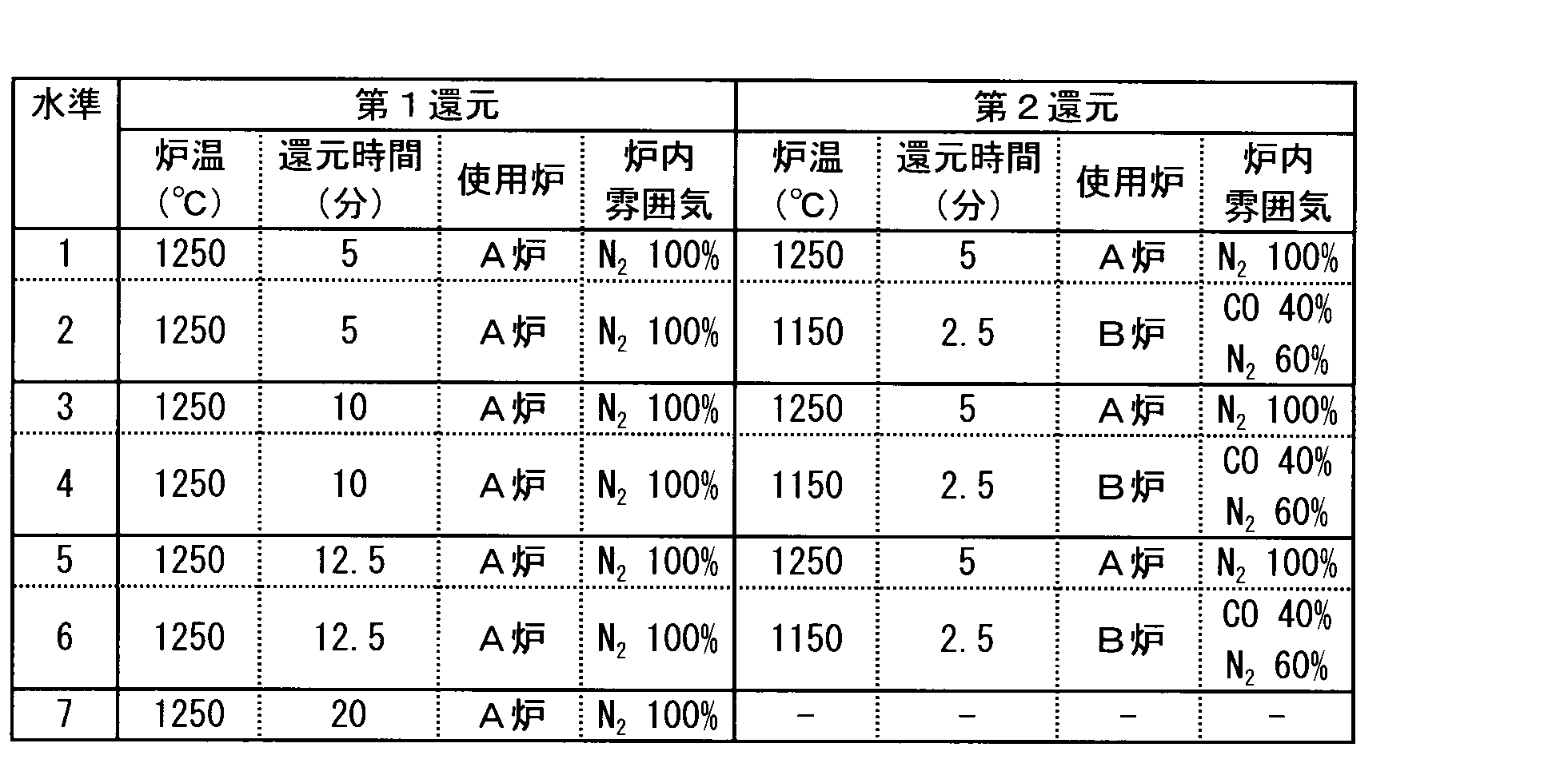
- Example 1 In order to confirm the optimal load distribution in the 1st reduction furnace and the 2nd reduction furnace, the iron oxide containing raw material which mixed the electric furnace dust with the melting furnace dust which is inferior powdered iron oxide raw material and coal are agglomerated. A reduction experiment of the experimental agglomerates (hereinafter referred to as “tablets”) was conducted.
- the furnace A is an experimental electric furnace in which the gas composition in the furnace is maintained at N 2 : 100% and the furnace temperature is maintained at 1250 ° C.
- the furnace B has a gas composition in the furnace (CO: 40% + N 2 : 60%) This is an electric furnace for experiments in which the furnace temperature is maintained at 1150 ° C.
- the furnace atmosphere is a stronger reducing atmosphere than the A furnace, but the furnace temperature is lower by 100 ° C. Table 1 shows the experimental conditions.
- the tablet was allowed to react in a furnace of A furnace for a predetermined time.
- the furnace temperature is sufficiently high at 1250 ° C, and since the tablet is also equipped with charcoal material, the heat transferred from the furnace atmosphere to the tablet surface by radiation is conducted into the tablet and the charcoal is gas. CO gas is generated and the reduction reaction proceeds.
- the reduction reaction so far is referred to as a first stage, and the subsequent reduction reaction is referred to as a second stage.
- the atmosphere in the furnace B is maintained in a strong reducing atmosphere of (CO: 40% + N 2 : 60%), and the tablet reduction reaction is expected to proceed faster than in the furnace A furnace. Therefore, in the B furnace, the furnace temperature was set lower, or the reaction time was set shorter so that the total reaction time was shorter than the tablet continuously reduced in the A furnace.
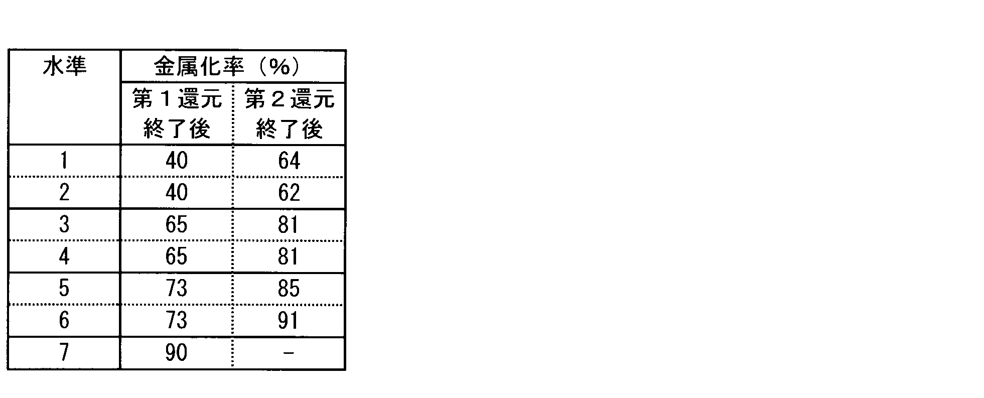
- Table 2 shows the analysis result of the metallization rate of the tablet after the first stage and the second reduction reaction shown in Table 1.
- Level 3 is a reaction for 15 minutes in an A furnace at 1250 ° C. with N 2 : 100%.
- the furnace temperature is 1150 ° C. and the furnace of the B furnace in a strong reducing atmosphere (CO: 40%) is 2.5 minutes in total. It was made to react for 1 minute.
- the total reaction time is 2.5 minutes shorter than in level 3, and the final metallization rate after the completion of the second reduction is level 3 even though the furnace temperature of the second reduction furnace is 100 ° C. lower. Can maintain the same value. That is, it is shown that the reaction rate of the tablet is greatly improved by switching the inside of the furnace to a strong reducing atmosphere during the reduction reaction.
- level 6 in which the total reaction time is shortened and the furnace temperature of the second reduction furnace is lowered to 1150 ° C. has a higher metallization rate.
- Level 1 and Level 2 the first reduction time is 5 minutes, and then the product is reduced continuously for 5 minutes in the A furnace (Level 1), and the second stage is the B furnace in the strong reducing atmosphere.
- Level 2 The metallization rates of products reduced at 2.5 ° C. for 2.5 minutes (level 2) were compared.
- the metallization rate of the second reduction product is higher in the level 1 that is continuously reduced in the furnace A than in the level 2 that is subjected to the second reduction in the furnace B. .
- the metallization rate at the end of the first reduction is as low as 40%, and in the second stage, sufficient pores that can diffuse the reducing gas in the furnace into the first reduction product are not generated. It is estimated to be.
- the reduction time in the first stage A furnace was increased to 20 minutes.
- the metallization rate of the first reduction product has reached 90%. Therefore, in this case, there is no need to bother to add a facility and perform the second reduction, and only the first stage reduction is sufficient.
- the first reduction product obtained by the first reduction in the A furnace is further (1) continuously reduced in the A furnace for 5 minutes (levels 1, 3, 5, 7; ⁇ in the figure) And (2) the second reduction product after completion of the reduction in the second stage in A furnace or B furnace when reduced in B furnace for 2.5 minutes (level 2, 4, 6, ⁇ in the figure) And the metallization rate (%) of the first reduction product after completion of the first reduction in the furnace A is shown.
- the metallization rate of the first reduction product at the end of the first stage is a certain value or more.
- reduced iron whose metallization rate at the end of the first stage has reached 90% can be used as a product as it is.
- Example 2 Next, an experiment was conducted to evaluate the influence of the furnace atmosphere on the metallization rate in the second reduction furnace.
- a furnace is an experimental electric furnace in which the gas composition in the furnace is maintained at N 2 : 100% and the furnace temperature is maintained at 1250 ° C.
- B furnace is a furnace in which the inside of the furnace can be controlled in a reducing atmosphere, and the furnace temperature is 1150 ° C.
- This is an experimental electric furnace held in The tablet used is the same as in Example 1.
- the tablet reacted for 10 minutes in the furnace A was quickly moved into the furnace B, and the second reduction reaction was performed in the furnace B.
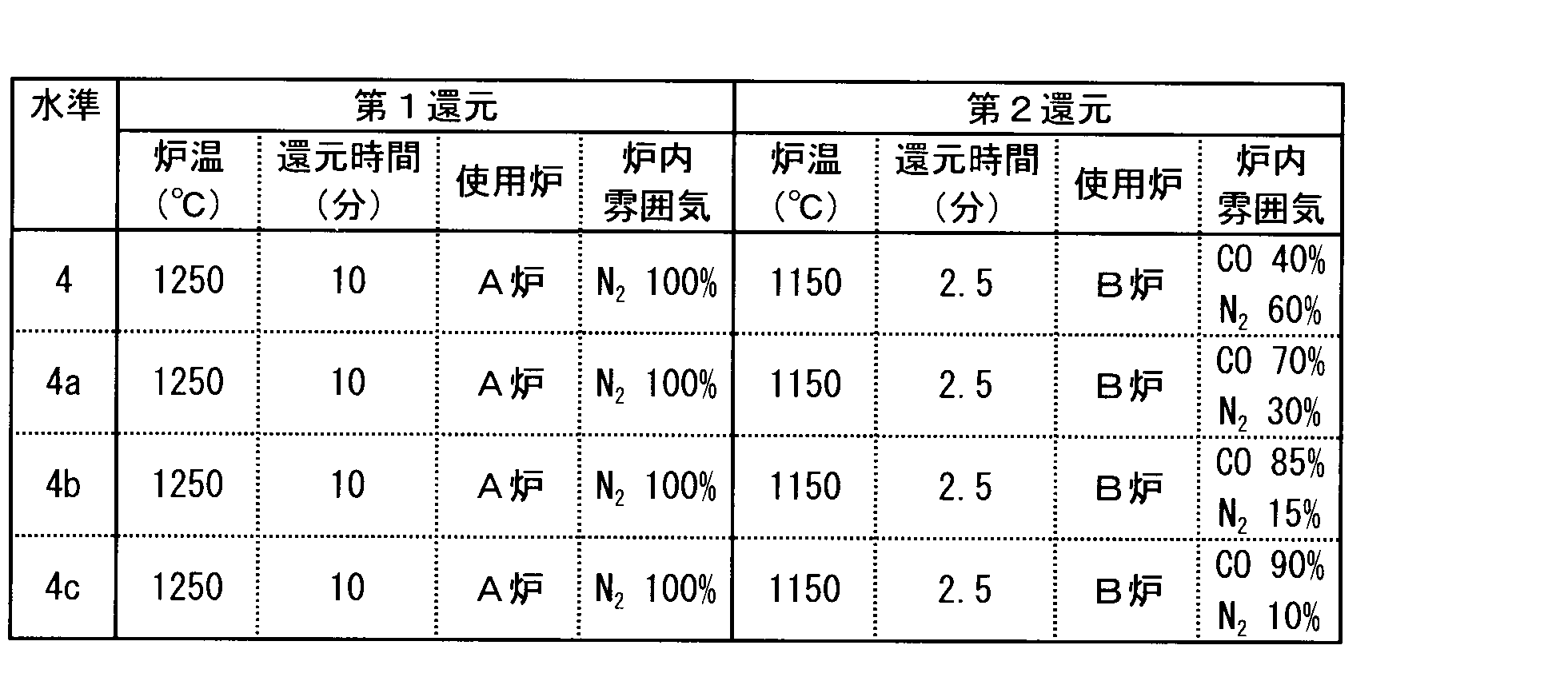
- the CO concentration in the B furnace was changed to 40%, 70%, 85%, and 90%, and the influence on the metallization rate of the tablet was evaluated.
- Table 3 shows each experimental condition. Among these, the level 4 where the CO concentration in the B furnace in the second stage is 40% is the same as the level 4 of the first embodiment.
- Table 4 shows the experimental results. It can be seen that when the CO concentration in the B furnace is increased by comparing the levels 4a and 4b with the level 4, the metallization rate after the end of the second stage also increases. However, the metallization rate of level 4c, which is 90% by further increasing the CO concentration, is the same value as level 4b of CO: 85%.
- FIG. 3 shows the relationship between the metalization rate (%) of the second reduction product after completion of the second reduction at levels 4, 4a, 4b, and 4c and the CO concentration (%) in the second reduction furnace (B furnace). Indicates. From FIG. 3, although the metallization rate is increased by increasing the CO concentration in the second reduction furnace, the effect on the metallization rate is not limited even if the CO concentration exceeds 85% even in a strong reducing atmosphere. You can see that there is almost no.
- Example 3 Two experimental reduction furnaces (A furnace and B furnace) were prepared.
- the A furnace is a rotary hearth type reduction furnace in which the gas composition in the furnace is maintained at N 2 : 100% and the furnace temperature is maintained at 1250 ° C.
- the furnace B has a gas composition in the furnace (CO: 30% + N 2 : 70%), and a small experimental shaft furnace of ⁇ 120 ⁇ 1200 mmH with the furnace temperature maintained at 1150 ° C.
- the furnace atmosphere is a stronger reducing atmosphere than the A furnace, but the furnace temperature is lower by 100 ° C.
- the finishing reduction conditions are as follows. ⁇ Shaft furnace: Inner diameter 120 x Height 1200mm -Furnace temperature: 1150 ° C -Furnace atmosphere: CO 30% + N 2 70% Table 5 shows the experimental conditions.
- the tablet was reacted in the furnace of the A furnace for a predetermined time.
- the atmosphere in the furnace B is maintained in a strong reducing atmosphere of (CO: 30% + N 2 : 70%), and the tablet reduction reaction is expected to proceed faster than in the furnace A. Therefore, in the B furnace, the furnace temperature was set lower, or the reaction time was set shorter so that the total reaction time was shorter than the tablet continuously reduced in the A furnace.
- Table 6 shows the analysis results of the metallization rate of the tablet after the completion of the first stage and the second reduction reaction shown in Table 5.
- Level 3 is a reaction for 15 minutes in an A furnace at 1250 ° C. with N 2 : 100%.
- the furnace temperature is 1150 ° C.
- the furnace of the B furnace in the strong reducing atmosphere (CO: 30%) is 2.5 minutes for a total of 12.5. It was made to react for 1 minute.
- the total reaction time is 2.5 minutes shorter than in level 3, and the final metallization rate after the completion of the second reduction is level 3 even though the furnace temperature of the second reduction furnace is 100 ° C. lower. Can maintain the same value. That is, it is shown that the reaction rate of the tablet is greatly improved by switching the inside of the furnace to a strong reducing atmosphere during the reduction reaction.
- level 6 in which the total reaction time is shortened and the furnace temperature of the second reduction furnace is lowered to 1150 ° C. has a higher metallization rate.
- Level 1 and Level 2 the first reduction time is 5 minutes, and then the product is reduced continuously for 5 minutes in the A furnace (Level 1), and the second stage is the B furnace in the strong reducing atmosphere.
- Level 2 The metallization rates of products reduced at 2.5 ° C. for 2.5 minutes (level 2) were compared.
- the metallization rate of the second reduction product is higher in the level 1 that is continuously reduced in the furnace A than in the level 2 that is subjected to the second reduction in the furnace B. .
- the metallization rate at the end of the first reduction is as low as 45%, and in the second stage, sufficient pores that can diffuse the reducing gas in the furnace into the first reduction product are not generated. It is estimated to be.
- the reduction time in the first stage A furnace was increased to 20 minutes.
- the metallization rate of the first reduction product has reached 91%. Therefore, in this case, it is not necessary to add the facility to perform the second reduction, and only the reduction by the rotary hearth type reduction furnace in the first stage is sufficient.
- Example 4 Melting furnace dust (inferior quality powdery iron oxide raw material) and coal were mixed agglomerated raw material agglomerate (in mass%, the metal Fe: 1%, FeO: 38 %, Fe 2 O 3: 31%, C : 14%) was reduced in a rotary hearth type reduction furnace (first stage) at a furnace temperature of 1250 ° C. to produce a first reduction product.
- This first reduction product was put into a small rotary kiln having a diameter of 300 ⁇ 3400 mm, and the final reduction (second reduction) of the first reduction product was performed.
- the finishing reduction conditions are as follows.
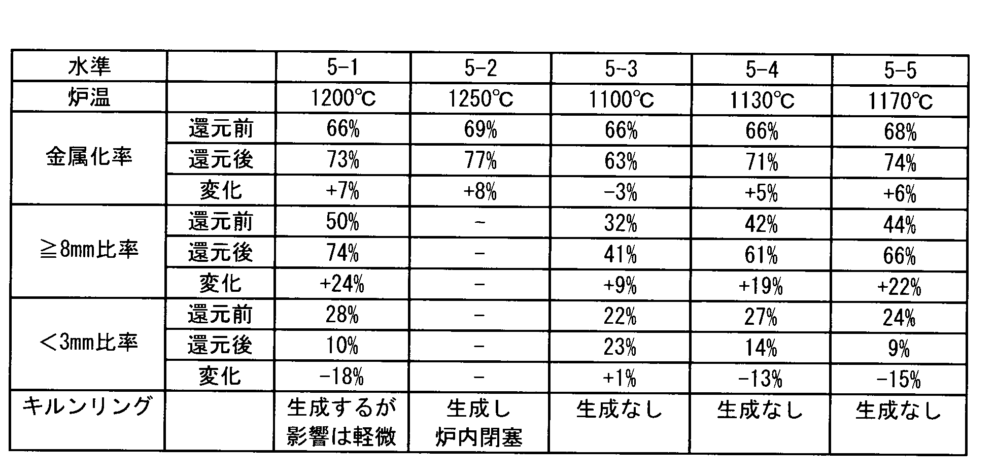
- Rotary kiln Inner diameter 300 ⁇ Length 3400mm ⁇ Rotary kiln speed: 3.2rpm ⁇ First reduction product input: 120 kg / h ⁇ First reduction product residence time: 20 minutes ⁇ Burner fuel: LPG -Combustion air ratio: 0.7 (CO concentration in the furnace: 20% by volume) Table 7 shows the results of the furnace temperature and the finish reduction.
- the final reduction was performed with the furnace temperature of the rotary kiln (second stage) set to 1250 ° C.
- the kiln ring was generated in the furnace and rapidly grew to close the kiln furnace. It was difficult to continue.
- Level 5-3 the final reduction was performed with the furnace temperature of the rotary kiln (second stage) set to 1100 ° C, but the metallization rate was -3%, the ratio of reduced iron with a particle size of 8 mm or more was + 9%, and the particle size was 3 mm.
- the ratio of the reduced iron below is + 1%, indicating that neither the reduction reaction nor the granulation progressed.
- Level 5-4 the final reduction was performed with the furnace temperature of the rotary kiln (second stage) set to 1130 ° C.
- the reduction reaction It can be seen that the granulation is progressing together. Also, no kiln ring formation was observed in the rotary kiln furnace.
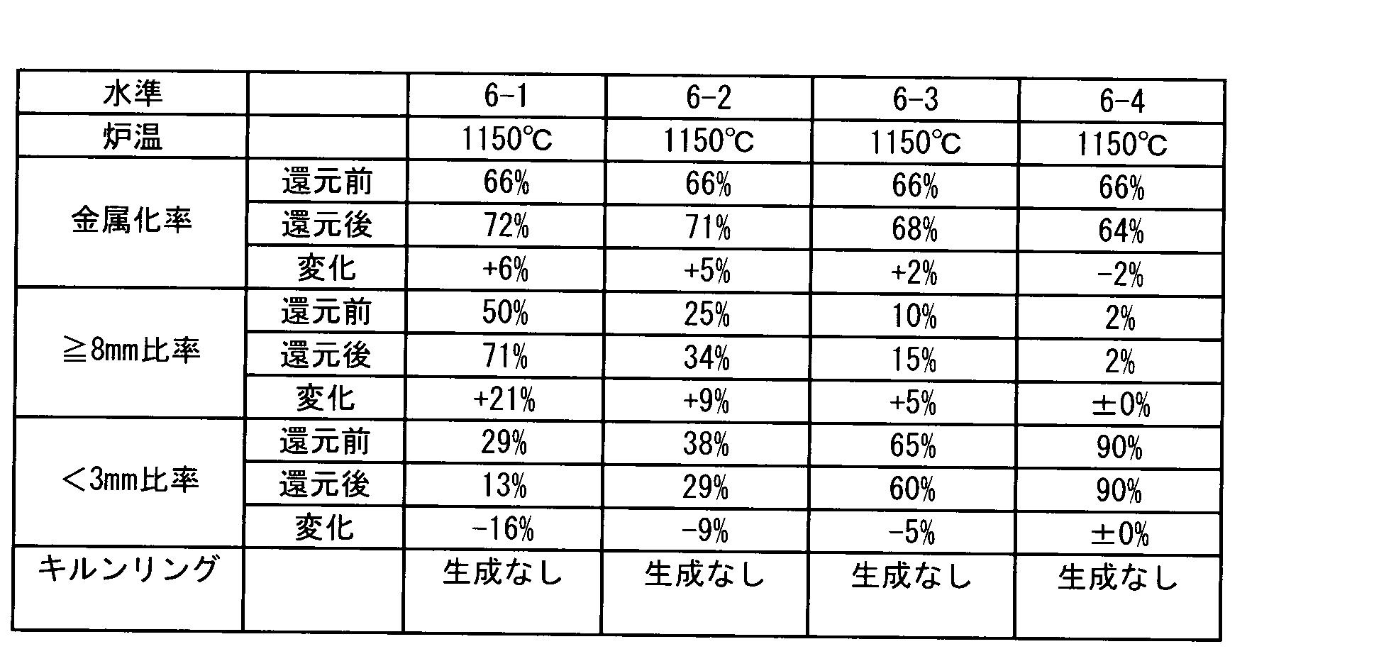
- Example 5 Melting furnace dust (inferior quality powdery iron oxide raw material) and the agglomerate was agglomerated by mixing the coal (in mass%, the metal Fe: 1%, FeO: 38 %, Fe 2 O 3: 31%, C: 14%) in a rotary hearth type reduction furnace (first stage) at a furnace temperature of 1250 ° C., and then subjected to an appropriate classification treatment, and the ratio of the particle size of less than 3 mm is 29% by mass, 38% by mass, 65% by mass.
- the 1st reduction product of the mass% and 90 mass% was manufactured. These first reduction products were charged into a small rotary kiln and subjected to final reduction (second stage).
- the furnace temperature of the kiln was 1150 ° C.
- the finishing reduction conditions are as follows. ⁇ Rotary kiln: Inner diameter 300 ⁇ Length 3400mm ⁇ Rotary kiln speed: 3.2rpm ⁇ First reduction product input: 120 kg / h ⁇ First reduction product residence time: 20 minutes ⁇ Burner fuel: LPG -Combustion air ratio: 0.7 (CO concentration in the furnace: 20% by volume) Experimental conditions and results are shown in Table 8 and FIG.
- FIG. 5 shows the results of Table 8, with the ratio of less than 3 mm (mass%) of the first reduction product on the horizontal axis, the amount of change in metallization rate in the heating / reduction treatment in the rotary kiln (second reduction furnace) ( ⁇ %) Is shown on the vertical axis.
- FIG. 5 shows that when the ratio of the first reduction product of less than 3 mm exceeds 75% by mass, the reduction reaction does not proceed in the rotary kiln furnace.
- Example 6 Melting furnace dust (inferior quality powdery iron oxide raw material) and the agglomerate was agglomerated by mixing the coal (in mass%, the metal Fe: 1%, FeO: 38 %, Fe 2 O 3: 31%, C: 14%) in a rotary hearth type reduction furnace (first stage) at a furnace temperature of 1250 ° C., and then classified according to a certain standard particle diameter, and only the undersieved product is charged into a small rotary kiln (second stage). The final reduction (second stage) was performed.
- the finishing reduction conditions are as follows. ⁇ Rotary kiln: Inner diameter 300 ⁇ Length 3400mm ⁇ Rotary kiln speed: 3.2rpm -Furnace temperature of rotary kiln: 1150 ° C ⁇ Burner fuel: LPG -Combustion air ratio: 0.7 (CO concentration in the furnace: 20% by volume) Experimental conditions and results are shown in Table 9 and FIG.
- Level 7-1 shows the results when the entire amount is reduced with a rotary kiln without first classifying the first reduction product.
- the entire processing amount (100%, 20.0 t / h) in the first stage rotary hearth type reduction furnace is finished and reduced by the rotary kiln.
- the rate is 7.9%.
- Level 7-2 the first reduction product discharged from the rotary hearth type reduction furnace is classified with a reference diameter of 16 mm, and only the bottom part of the sieve is finished and reduced with a rotary kiln, and the top part of the sieve is bypassed. Both were mixed into a product reduced iron.
- the mass ratio of the sieving product is 63% of the total processing amount of the first reduction product, and the equipment specifications of the second stage rotary kiln reduction furnace can be reduced to about 60% compared to the case of processing the entire amount. Is shown.
- the final ⁇ metallization rate is 7.6%, which is an increase in the reduction rate comparable to the level 7-1 ⁇ metallization rate of 7.9%.
- Level 7-3 the classification standard diameter was set to 12 mm, and similarly to Level 7-2, the sieved product was finish-reduced with a rotary kiln and mixed with the bypassed sieved product to obtain product reduced iron.
- the mass ratio of the sieved product is 48% with respect to the total processing amount of the first reduction product, and the rotary kiln spec can be reduced to about half.
- the final ⁇ metallization rate is also 7.3%, and the finishing reduction allowance of the same level can be maintained as compared with the level 7-1 and the level 7-2.
- the classification reference diameter was reduced to 4 mm.
- the mass ratio of the under-sieving portion is only 16% with respect to the total amount of the first reduction product, and it can be estimated that the scale of the rotary kiln can be significantly reduced as compared with the case where the total amount is processed.
- the ⁇ metallization rate is 2.2%, and the final increase in the metallization rate is significantly smaller than the level 7-1 that is not subjected to prior classification treatment. This is presumably because the classification standard diameter was as small as 4 mm, and the mass ratio of less than 3 mm in the under-sieving portion reached 73.0%, which hindered the progress of finishing reduction in the rotary kiln.
- FIG. 6 shows the correlation between the sieving classification ratio (mass%) obtained as a result of the classification of the first reduction product and the final product metallization ratio (%) of the reduced iron in each level of this example. Show. In addition, the metallization rate 81.4 (%) of the product reduced iron when the total amount of the first reduction product is finished and reduced in a rotary kiln type reduction furnace without being classified is shown at the underclassification ratio of 100%. ing.
- FIG. 6 shows that the classification reference diameter may be determined so that the mass percentage of the total amount of the first reduction product of the sieving product produced by classification is 50% or more.
- the present invention can be used in the steel industry.
- the iron oxide contained in the iron-making dust discharged in the iron-making process can be used again as a raw material for iron-making by reducing it to metal iron according to the present invention.
Landscapes
- Engineering & Computer Science (AREA)
- Chemical & Material Sciences (AREA)
- Manufacturing & Machinery (AREA)
- Materials Engineering (AREA)
- Metallurgy (AREA)
- Organic Chemistry (AREA)
- Mechanical Engineering (AREA)
- General Engineering & Computer Science (AREA)
- Manufacture Of Iron (AREA)
- Manufacture And Refinement Of Metals (AREA)
Abstract
Description
特許文献5には、流動床反応装置により、ヘマタイト又はゲーサイトを、事前に、還元ガスでマグネタイトまで還元し、その後、得られた半還元生成物に炭素質還元材を添加した混合物にマイクロ波を照射して加熱することで、さらに還元し、金属鉄を得る方法が記載されている。
また第2還元においては、還元性ガスが第1還元生成物の気孔から内部に浸透し酸化鉄を還元する。そのため、第2還元においては一定の濃度の還元性ガスが必要になる。そこで発明者らは、第2還元における還元雰囲気中のCOガスの濃度を10体積%以上85体積%以下にすることにより、効率よく第1還元生成物を還元することができることを見出した。
但し、あまり粉化したものが多過ぎても第2還元の進行が妨げられる。発明者らは、第2還元炉としてロータリーキルン式還元炉を適用した場合には、粒径3mm未満の還元生成物を75%以下含有する還元生成物であれば、ロータリーキルン式還元炉で第2還元が十分に進行することを確認した。
(1)
酸化鉄含有原料と還元材を混合して塊成化した塊成物を、連続した2段階の還元処理をする還元鉄の製造方法であって、
(i)第1の還元処理に回転炉床式還元炉を適用し、次いで、
(ii)第2の還元処理にロータリーキルン式又はシャフト式の還元炉を適用し、該第2の還元処理において、還元雰囲気中のCOガスの濃度が10体積%以上85体積%以下であることを特徴とする還元鉄の製造方法。
(2)
前記第1の還元処理にて生成する還元生成物である第1還元生成物の金属化率が65質量%以上90質量%以下であることを特徴とする(1)に記載の還元鉄の製造方法。
(3)
前記第2の還元処理にロータリーキルン式還元炉を適用して前記第1還元生成物を処理する場合において、該ロータリーキルン式還元炉内の雰囲気温度が1100℃超、1200℃以下であることを特徴とする(1)または(2)に記載の還元鉄の製造方法。
(4)
前記第1還元処理にて生成する第1還元生成物を、分級篩下の還元生成物が粒径3mm未満の還元生成物を75%以下だけ含有するものとなるように分級し、ロータリーキルン式還元炉を適用して前記分級篩下の還元生成物を前記第2の還元処理を行って得られた第2還元生成物と、前記分級で篩上となった第1還元生成物を混合することを特徴とする前記(1)~(3)のいずれか1項に記載の還元鉄の製造方法。
(5)
前記酸化鉄含有原料が、少なくとも溶解炉ダスト、電気炉ダスト、圧延スケール、酸洗・中和スラッジのいずれかを含むものであることを特徴とする(1)~(4)のいずれか1項に記載の還元鉄の製造方法。
(6)
酸化鉄含有原料と還元材を混合して塊成化した原料塊成物を連続した2つの還元炉を用いて還元する還元鉄の製造設備であって、
(a)前記原料塊成物を還元する、第1の還元炉として回転炉床式還元炉を、
(b)前記第1の還元炉で生成される還元生成物である第1還元生成物をさらに還元する、第2の還元炉としてロータリーキルン式又はシャフト式の還元炉を備えることを特徴とする還元鉄の製造設備。
(7)
さらに前記第1還元生成物を分級する分級設備を備え、前記分級設備で篩下となった第1還元生成物を、ロータリーキルン式還元炉を適用した前記第2の還元炉に装入し、前記第2の還元炉で生成した第2還元生成物と、前記分級設備で篩上となった第1還元生成物を混合する設備を備えることを特徴する前記(6)に記載の還元鉄の製造設備。
(i)第1の還元炉として、回転炉床式還元炉を用い、次いで、
(ii)第2の還元炉として、ロータリーキルン式又はシャフト式の還元炉を用い、該第2の還元処理において、還元雰囲気中のCOガスの濃度が10体積%以上85体積%以下とする
ことを特徴とする。
(a)前記塊成物を受け入れ、還元する、第1段階の回転炉床式還元炉と、
(b)該回転炉床式還元炉の後段に設置され、該回転炉床式還元炉から排出される還元鉄を受け入れ、該還元鉄をさらに還元する、第2段階のロータリーキルン式又はシャフト式の還元炉を備える
ことを特徴とする。
即ち、第1還元生成物の仕上げ還元を行う第2還元炉の内部の還元性ガスの濃度を高めれば、還元性ガスが、第1還元生成物の内部へ拡散し酸化鉄を還元できると考えた。
即ち、ロータリーキルン式還元炉の場合は、缶体の回転による第1還元生成物の撹拌により、また、シャフト式還元炉の場合は、炉内へのガスの押し込みによるガス流れと第1還元生成物の接触により、第1還元生成物の気孔内部へ還元性ガスの拡散・侵入を促進することができる。
以上のとおり、本発明においては、第1還元生成物が高気孔率であることを、第2還元炉における還元反応の促進のために有効に活用している。
以上のことから、第1還元が完了した後の第1還元生成物の金属化率は65%以上90%以下であることが望ましい。
しかし、第2段階のロータリーキルン式還元炉の炉温が1200℃を超えると、キルンリングが顕著に生成するので、炉温は1200℃以下が好ましい。
それ故、第1還元生成物は、粒径3mm未満のものを75質量%以下にすることが好ましい。
(a)粉状酸化鉄原料と炭素質還元材を混合して塊成化した原料塊成物を加熱・還元する、第1段階の回転炉床式還元炉、
(b)上記回転炉床式還元炉の後段に設置され、第1段階の回転炉床式還元炉から排出される還元生成物(第一還元生成物)を分級する分級設備、及び、
(c)上記篩下の還元生成物のみを加熱・還元する、第2段階のロータリーキルン式還元炉
を備えることを特徴とする。
第1還元炉と第2還元炉における最適な負荷配分を確認するため、劣質粉状酸化鉄原料である溶解炉ダストに電気炉ダストを混合した酸化鉄含有原料と石炭を混合して塊成化した実験用塊成物(以下「タブレット」という。)の還元実験を実施した。
次に、第2還元炉において炉内雰囲気が金属化率に与える影響を評価する実験を行った。本実験においても実験用還元炉を2基(A炉とB炉)使用した。A炉は、炉内ガス組成をN2:100%、炉温を1250℃に保持した実験用電気炉であり、B炉は、炉内を還元雰囲気に制御できる炉で、炉温を1150℃に保持した実験用電気炉である。用いたタブレットは実施例1と同じものである。
図3から、第2還元炉内のCO濃度を増加させることで、金属化率も増加していくものの、CO濃度が85%を超えて強還元雰囲気にしても、金属化率に及ぼす効果はほとんどないことが分かる。
実験用還元炉を2基(A炉とB炉)準備した。ここでのA炉は、炉内ガス組成をN2:100%、炉温を1250℃に保持した回転炉床式還元炉であり、B炉は、炉内ガス組成を(CO:30%+N2:70%)、炉温を1150℃に保持したφ120×1200mmHの小型実験用シャフト炉である。B炉は、炉内雰囲気がA炉より強還元雰囲気であるが、炉温が100℃低くなっている。
・シャフト炉:内径120×高さ1200mm
・炉温:1150℃
・炉内雰囲気:CO 30%+N2 70%
実験条件を表5に示す。
溶解炉ダスト(劣質粉状酸化鉄原料)と石炭を混合して塊成化した原料塊成物(質量%で、金属Fe:1%、FeO:38%、Fe2O3:31%、C:14%)を炉温1250℃の回転炉床式還元炉(第1段階)で還元して第1還元生成物を製造した。この第1還元生成物を、φ300×3400mmLの小型ロータリーキルンに投入して、第1還元生成物の仕上げ還元(第2還元)を実施した。
・ロータリーキルンの回転数:3.2rpm
・第1還元生成物投入量:120kg/h
・第1還元生成物滞留時間:20分
・バーナ燃料:LPG
・燃焼空気比:0.7(炉内CO濃度:20体積%)
炉温および仕上げ還元の結果を表7に示す。
溶解炉ダスト(劣質粉状酸化鉄原料)と石炭を混合して塊成化した塊成物(質量%で、金属Fe:1%、FeO:38%、Fe2O3:31%、C:14%)を、炉温1250℃の回転炉床式還元炉(第1段階)で還元した後、適切な分級処理を施し、粒径3mm未満の比率が、29質量%、38質量%、65質量%、及び、90質量%の第1還元生成物を製造した。これら第1還元生成物を、小型ロータリーキルンに装入して仕上げ還元(第2段階)を実施した。該キルンの炉温は1150℃とした。
・ロータリーキルン:内径300×長さ3400mm
・ロータリーキルンの回転数:3.2rpm
・第1還元生成物投入量:120kg/h
・第1還元生成物滞留時間:20分
・バーナ燃料:LPG
・燃焼空気比:0.7(炉内CO濃度:20体積%)
実験条件と結果を表8及び図5に示す。
溶解炉ダスト(劣質粉状酸化鉄原料)と石炭を混合して塊成化した塊成物(質量%で、金属Fe:1%、FeO:38%、Fe2O3:31%、C:14%)を、炉温1250℃の回転炉床式還元炉(第1段階)で還元した後、予めある基準粒径で分級し、篩下品のみを小型ロータリーキルン(第2段階)に装入して仕上げ還元(第2段階)を実施した。
・ロータリーキルン:内径300×長さ3400mm
・ロータリーキルンの回転数:3.2rpm
・ロータリーキルンの炉温:1150℃
・バーナ燃料:LPG
・燃焼空気比:0.7(炉内CO濃度:20体積%)
実験条件と結果を表9及び図6に示す。



Claims (7)
- 酸化鉄含有原料と還元材を混合して塊成化した塊成物を、連続した2段階の還元処理をする還元鉄の製造方法であって、
(i)第1の還元処理に回転炉床式還元炉を適用し、次いで、
(ii)第2の還元処理にロータリーキルン式又はシャフト式の還元炉を適用し、
該第2の還元処理において、還元雰囲気中のCOガスの濃度が10体積%以上85体積%以下であることを特徴とする還元鉄の製造方法。
- 前記第1の還元処理にて生成する還元生成物である第1還元生成物の金属化率が
65質量%以上90質量%以下であることを特徴とする請求項1に記載の還元鉄の製造方法。
- 前記第2の還元処理にロータリーキルン式還元炉を適用して前記第1還元生成物を処理する場合において、該ロータリーキルン式還元炉内の雰囲気温度が1100℃超、1200℃以下であることを特徴とする請求項1または2に記載の還元鉄の製造方法。
- 前記第1の還元処理にて生成する第1還元生成物を、分級篩下の還元生成物が粒径3mm未満の還元生成物を75質量%以下だけ含有するものとなるように分級し、ロータリーキルン式還元炉を適用して前記分級篩下の還元生成物を前記第2の還元処理を行って得られた第2還元生成物と、前記分級で篩上となった第1還元生成物を混合することを特徴とする請求項1~3のいずれか1項に記載の還元鉄の製造方法。
- 前記酸化鉄含有原料が、少なくとも溶解炉ダスト、電気炉ダスト、圧延スケール、酸洗・中和スラッジのいずれかを含むものであることを特徴とする請求項1~4のいずれか1項に記載の還元鉄の製造方法。
- 酸化鉄含有原料と還元材を混合して塊成化した原料塊成物を連続した2つの還元炉を用いて還元する還元鉄の製造設備であって、
(a)前記原料塊成物を還元する、第1の還元炉として回転炉床式還元炉を、
(b)前記第1の還元炉で生成される還元生成物である第1還元生成物をさらに還元する、第2の還元炉としてロータリーキルン式又はシャフト式の還元炉を備えることを特徴とする還元鉄の製造設備。
- さらに前記第1還元生成物を分級する分級設備を備え、前記分級設備で篩下となった第1還元生成物を、ロータリーキルン式還元炉を適用した前記第2の還元炉に装入し、前記第2の還元炉で生成した第2還元生成物と、前記分級設備で篩上となった第1還元生成物を混合する設備を備えることを特徴する請求項6に記載の還元鉄の製造設備。
Priority Applications (3)
| Application Number | Priority Date | Filing Date | Title |
|---|---|---|---|
| JP2015535273A JP5825459B1 (ja) | 2014-03-11 | 2015-03-10 | 還元鉄の製造方法及び製造設備 |
| KR1020167017278A KR101714995B1 (ko) | 2014-03-11 | 2015-03-10 | 환원철의 제조 방법 및 제조 설비 |
| CN201580002585.3A CN105723002B (zh) | 2014-03-11 | 2015-03-10 | 还原铁的制造方法以及制造设备 |
Applications Claiming Priority (4)
| Application Number | Priority Date | Filing Date | Title |
|---|---|---|---|
| JP2014-047678 | 2014-03-11 | ||
| JP2014047678 | 2014-03-11 | ||
| JP2014-215688 | 2014-10-22 | ||
| JP2014215688 | 2014-10-22 |
Publications (1)
| Publication Number | Publication Date |
|---|---|
| WO2015137348A1 true WO2015137348A1 (ja) | 2015-09-17 |
Family
ID=54071791
Family Applications (1)
| Application Number | Title | Priority Date | Filing Date |
|---|---|---|---|
| PCT/JP2015/057034 Ceased WO2015137348A1 (ja) | 2014-03-11 | 2015-03-10 | 還元鉄の製造方法及び製造設備 |
Country Status (4)
| Country | Link |
|---|---|
| JP (1) | JP5825459B1 (ja) |
| KR (1) | KR101714995B1 (ja) |
| CN (1) | CN105723002B (ja) |
| WO (1) | WO2015137348A1 (ja) |
Cited By (1)
| Publication number | Priority date | Publication date | Assignee | Title |
|---|---|---|---|---|
| TWI865354B (zh) * | 2024-03-04 | 2024-12-01 | 中國鋼鐵股份有限公司 | 回收耐火材的處理方法 |
Families Citing this family (1)
| Publication number | Priority date | Publication date | Assignee | Title |
|---|---|---|---|---|
| KR102272196B1 (ko) * | 2019-08-22 | 2021-07-05 | 신광진 | 시멘트 제조 설비를 이용한 직접 환원철의 제조 설비 및 이를 이용한 제조 방법 |
Citations (4)
| Publication number | Priority date | Publication date | Assignee | Title |
|---|---|---|---|---|
| US1979729A (en) * | 1933-06-05 | 1934-11-06 | William D Brown | Production of sponge iron |
| US4443250A (en) * | 1982-03-20 | 1984-04-17 | Metallgesellschaft Aktiengesellschaft | Process of producing sponge iron by a direct reduction of iron oxide-containing materials |
| WO2003025231A1 (fr) * | 2001-09-14 | 2003-03-27 | Nippon Steel Corporation | Procede de production d'un agregat de fer reduit dans un four de reduction a sole rotative, agregat de fer reduit et procede de production de fonte brute |
| JP2009544846A (ja) * | 2006-07-21 | 2009-12-17 | コラス、テクノロジー、ベスローテン、フェンノートシャップ | 金属含有材料を還元生成物に還元するための方法および装置 |
Family Cites Families (8)
| Publication number | Priority date | Publication date | Assignee | Title |
|---|---|---|---|---|
| JPS5925910A (ja) | 1982-08-02 | 1984-02-10 | Kawasaki Heavy Ind Ltd | 純金属の製造方法および装置 |
| JP3004265B1 (ja) | 1998-11-24 | 2000-01-31 | 株式会社神戸製鋼所 | 炭材内装ペレット及び還元鉄製造方法 |
| JP4336437B2 (ja) | 2000-03-29 | 2009-09-30 | 住友重機械工業株式会社 | ロータリーキルンの制御方法及びその装置 |
| JP3723521B2 (ja) | 2002-04-03 | 2005-12-07 | 株式会社神戸製鋼所 | 高炉湿ダストを用いる還元鉄製造方法および粗酸化亜鉛製造方法 |
| CN101121950A (zh) * | 2007-09-21 | 2008-02-13 | 郭瑛 | 管式炉-竖炉双联煤基熔融还原炼铁法 |
| JP4348387B2 (ja) * | 2007-10-19 | 2009-10-21 | 新日本製鐵株式会社 | 予備還元鉄の製造方法 |
| JP5218196B2 (ja) | 2009-03-25 | 2013-06-26 | 新日鐵住金株式会社 | 酸化鉄含有物質の還元方法 |
| JP5475630B2 (ja) | 2010-12-15 | 2014-04-16 | 株式会社神戸製鋼所 | 還元鉄製造用塊成物、およびその製造方法 |
-
2015
- 2015-03-10 KR KR1020167017278A patent/KR101714995B1/ko active Active
- 2015-03-10 JP JP2015535273A patent/JP5825459B1/ja active Active
- 2015-03-10 CN CN201580002585.3A patent/CN105723002B/zh active Active
- 2015-03-10 WO PCT/JP2015/057034 patent/WO2015137348A1/ja not_active Ceased
Patent Citations (4)
| Publication number | Priority date | Publication date | Assignee | Title |
|---|---|---|---|---|
| US1979729A (en) * | 1933-06-05 | 1934-11-06 | William D Brown | Production of sponge iron |
| US4443250A (en) * | 1982-03-20 | 1984-04-17 | Metallgesellschaft Aktiengesellschaft | Process of producing sponge iron by a direct reduction of iron oxide-containing materials |
| WO2003025231A1 (fr) * | 2001-09-14 | 2003-03-27 | Nippon Steel Corporation | Procede de production d'un agregat de fer reduit dans un four de reduction a sole rotative, agregat de fer reduit et procede de production de fonte brute |
| JP2009544846A (ja) * | 2006-07-21 | 2009-12-17 | コラス、テクノロジー、ベスローテン、フェンノートシャップ | 金属含有材料を還元生成物に還元するための方法および装置 |
Cited By (1)
| Publication number | Priority date | Publication date | Assignee | Title |
|---|---|---|---|---|
| TWI865354B (zh) * | 2024-03-04 | 2024-12-01 | 中國鋼鐵股份有限公司 | 回收耐火材的處理方法 |
Also Published As
| Publication number | Publication date |
|---|---|
| JP5825459B1 (ja) | 2015-12-02 |
| CN105723002A (zh) | 2016-06-29 |
| KR101714995B1 (ko) | 2017-03-09 |
| JPWO2015137348A1 (ja) | 2017-04-06 |
| CN105723002B (zh) | 2018-03-27 |
| KR20160082267A (ko) | 2016-07-08 |
Similar Documents
| Publication | Publication Date | Title |
|---|---|---|
| RU2435868C1 (ru) | Способ получения брикетированного восстановленного железа и способ получения чугуна | |
| JP4757982B2 (ja) | 粒状金属鉄の歩留まり向上方法 | |
| CN101790590B (zh) | 还原铁丸的制造方法及生铁的制造方法 | |
| JP2004156140A (ja) | フェロニッケルおよびフェロニッケル精錬原料の製造方法 | |
| WO2010117008A1 (ja) | 金属鉄の製法 | |
| JP3635256B2 (ja) | 酸化鉄の還元方法 | |
| EP1718775B1 (en) | Pre-treatment process for feed material for direct reduction process | |
| JP5825459B1 (ja) | 還元鉄の製造方法及び製造設備 | |
| CN107354257A (zh) | 一种金属铁的生产方法 | |
| JP5521387B2 (ja) | 還元鉄成形体の製造方法、及び銑鉄の製造方法 | |
| JPH1112619A (ja) | 還元鉄の製造方法 | |
| JP5971482B2 (ja) | 塊成鉱の製造方法 | |
| JP4918754B2 (ja) | 半還元焼結鉱およびその製造方法 | |
| JP3732024B2 (ja) | 還元鉄ペレットの製造方法 | |
| JP3864506B2 (ja) | 半還元鉄塊成鉱およびその製造方法ならびに銑鉄の製造方法 | |
| JPH1129806A (ja) | 溶銑製造方法 | |
| JP2014031528A (ja) | 高炉用原料の製造方法 | |
| JP5915864B2 (ja) | 塊成鉱の製造方法 | |
| JP5892317B2 (ja) | 高炉用原料の製造方法 | |
| JP3355967B2 (ja) | 還元鉄の製造方法 | |
| JPH11302712A (ja) | 鉄酸化物の還元溶解精錬方法 | |
| Tokuda | Rotary Hearth Furnace Process | |
| JP5892318B2 (ja) | 塊成鉱の製造方法 | |
| CN120752354A (zh) | 用于固体颗粒状材料的连续预还原的方法和系统 | |
| JPH1129807A (ja) | 溶銑製造方法 |
Legal Events
| Date | Code | Title | Description |
|---|---|---|---|
| ENP | Entry into the national phase |
Ref document number: 2015535273 Country of ref document: JP Kind code of ref document: A |
|
| 121 | Ep: the epo has been informed by wipo that ep was designated in this application |
Ref document number: 15762016 Country of ref document: EP Kind code of ref document: A1 |
|
| ENP | Entry into the national phase |
Ref document number: 20167017278 Country of ref document: KR Kind code of ref document: A |
|
| NENP | Non-entry into the national phase |
Ref country code: DE |
|
| 122 | Ep: pct application non-entry in european phase |
Ref document number: 15762016 Country of ref document: EP Kind code of ref document: A1 |