WO2015137239A1 - Appareil de commutation ayant une fonction sans fil - Google Patents
Appareil de commutation ayant une fonction sans fil Download PDFInfo
- Publication number
- WO2015137239A1 WO2015137239A1 PCT/JP2015/056564 JP2015056564W WO2015137239A1 WO 2015137239 A1 WO2015137239 A1 WO 2015137239A1 JP 2015056564 W JP2015056564 W JP 2015056564W WO 2015137239 A1 WO2015137239 A1 WO 2015137239A1
- Authority
- WO
- WIPO (PCT)
- Prior art keywords
- terminal
- connector
- switch device
- wireless function
- pin
- Prior art date
Links
Images


Classifications
-
- H—ELECTRICITY
- H01—ELECTRIC ELEMENTS
- H01H—ELECTRIC SWITCHES; RELAYS; SELECTORS; EMERGENCY PROTECTIVE DEVICES
- H01H9/00—Details of switching devices, not covered by groups H01H1/00 - H01H7/00
- H01H9/16—Indicators for switching condition, e.g. "on" or "off"
- H01H9/168—Indicators for switching condition, e.g. "on" or "off" making use of an electromagnetic wave communication
-
- H—ELECTRICITY
- H01—ELECTRIC ELEMENTS
- H01H—ELECTRIC SWITCHES; RELAYS; SELECTORS; EMERGENCY PROTECTIVE DEVICES
- H01H13/00—Switches having rectilinearly-movable operating part or parts adapted for pushing or pulling in one direction only, e.g. push-button switch
- H01H13/02—Details
- H01H13/023—Light-emitting indicators
-
- H—ELECTRICITY
- H01—ELECTRIC ELEMENTS
- H01H—ELECTRIC SWITCHES; RELAYS; SELECTORS; EMERGENCY PROTECTIVE DEVICES
- H01H13/00—Switches having rectilinearly-movable operating part or parts adapted for pushing or pulling in one direction only, e.g. push-button switch
- H01H13/02—Details
- H01H13/04—Cases; Covers
-
- H—ELECTRICITY
- H01—ELECTRIC ELEMENTS
- H01H—ELECTRIC SWITCHES; RELAYS; SELECTORS; EMERGENCY PROTECTIVE DEVICES
- H01H13/00—Switches having rectilinearly-movable operating part or parts adapted for pushing or pulling in one direction only, e.g. push-button switch
- H01H13/50—Switches having rectilinearly-movable operating part or parts adapted for pushing or pulling in one direction only, e.g. push-button switch having a single operating member
- H01H13/52—Switches having rectilinearly-movable operating part or parts adapted for pushing or pulling in one direction only, e.g. push-button switch having a single operating member the contact returning to its original state immediately upon removal of operating force, e.g. bell-push switch
-
- H—ELECTRICITY
- H01—ELECTRIC ELEMENTS
- H01Q—ANTENNAS, i.e. RADIO AERIALS
- H01Q1/00—Details of, or arrangements associated with, antennas
- H01Q1/27—Adaptation for use in or on movable bodies
- H01Q1/32—Adaptation for use in or on road or rail vehicles
- H01Q1/3208—Adaptation for use in or on road or rail vehicles characterised by the application wherein the antenna is used
- H01Q1/3233—Adaptation for use in or on road or rail vehicles characterised by the application wherein the antenna is used particular used as part of a sensor or in a security system, e.g. for automotive radar, navigation systems
- H01Q1/3241—Adaptation for use in or on road or rail vehicles characterised by the application wherein the antenna is used particular used as part of a sensor or in a security system, e.g. for automotive radar, navigation systems particular used in keyless entry systems
-
- H—ELECTRICITY
- H01—ELECTRIC ELEMENTS
- H01Q—ANTENNAS, i.e. RADIO AERIALS
- H01Q7/00—Loop antennas with a substantially uniform current distribution around the loop and having a directional radiation pattern in a plane perpendicular to the plane of the loop
-
- B—PERFORMING OPERATIONS; TRANSPORTING
- B60—VEHICLES IN GENERAL
- B60R—VEHICLES, VEHICLE FITTINGS, OR VEHICLE PARTS, NOT OTHERWISE PROVIDED FOR
- B60R25/00—Fittings or systems for preventing or indicating unauthorised use or theft of vehicles
- B60R25/20—Means to switch the anti-theft system on or off
- B60R25/24—Means to switch the anti-theft system on or off using electronic identifiers containing a code not memorised by the user
-
- H—ELECTRICITY
- H01—ELECTRIC ELEMENTS
- H01H—ELECTRIC SWITCHES; RELAYS; SELECTORS; EMERGENCY PROTECTIVE DEVICES
- H01H2231/00—Applications
- H01H2231/026—Car
-
- H—ELECTRICITY
- H01—ELECTRIC ELEMENTS
- H01H—ELECTRIC SWITCHES; RELAYS; SELECTORS; EMERGENCY PROTECTIVE DEVICES
- H01H2300/00—Orthogonal indexing scheme relating to electric switches, relays, selectors or emergency protective devices covered by H01H
- H01H2300/03—Application domotique, e.g. for house automation, bus connected switches, sensors, loads or intelligent wiring
- H01H2300/032—Application domotique, e.g. for house automation, bus connected switches, sensors, loads or intelligent wiring using RFID technology in switching devices
Definitions
- the present invention relates to a switch device with a wireless function capable of communication operation by an antenna coil and switch operation by a knob.
- Patent Document 1 discloses a switch device used in an engine start system for a vehicle.
- a user of a vehicle applied to the above system has an electronic key (referred to as a portable device) instead of a conventional mechanical key.
- the vehicle collates the electronic key, and permits vehicle control such as engine starting when it is positively determined that the electronic key is a key of the vehicle.
- the portable device has a built-in battery and transmits a unique ID (identification) to the own device in response to a request signal from the vehicle.
- the vehicle determines whether the ID acquired from the portable device matches the reference ID, and allows vehicle control on condition that the ID acquired from the portable device matches the reference ID. Therefore, the engine can be started by operating the knob of the switch device installed near the driver's seat while the user carries the portable device.
- the portable device cannot transmit the ID in response to the request signal. That is, in this case, the user cannot start the engine even if the user operates the knob of the switch device while holding the portable device.
- an antenna coil is provided in the switch device in order to cope with a situation such as battery exhaustion. Drive radio waves are transmitted from the antenna coil when the knob of the switch device is operated.
- the portable device enters the transmission area of the driving radio wave, the portable device generates power from the driving radio wave and transmits an ID based on the generated power. Therefore, the engine can be started by operating the knob of the switch device while the user holds the portable device over the switch device.
- a switch device capable of performing a communication operation using an antenna coil and a switch operation using a knob suitable for the above countermeasure is defined as a switch device with a wireless function.
- the switch device 51 with a wireless function includes a case (not shown), and a substrate 52 on which necessary components are mounted is accommodated in the case.
- the mounting component of the substrate 52 includes an antenna unit.
- the antenna unit includes a bobbin 53, an antenna coil 54 wound around the bobbin 53, and a terminal 55 provided on the bobbin 53.
- Terminal 55 includes a first end and a second end protruding from bobbin 53.
- the end of the antenna coil 54 is wound around the tip of the first end of the terminal 55, and both are joined by caulking or the like.
- the tip of the second end of the terminal 55 is inserted into the hole of the substrate 52.
- the portion that has passed through the hole at the second end of the terminal 55 is soldered on the upper surface of the substrate 52.
- a terminal 57 of a connector 56 which is one of the mounted components, is soldered to a location different from the location where the terminal 55 is soldered on the substrate 52.
- the terminal 57 of the connector 56 is electrically connected to the terminal 55 of the antenna coil 54 through the conductive pattern of the substrate 52.
- the connector 56 is provided with another terminal serving as a medium for outputting a switch signal or the like accompanying operation of a knob (not shown) to an external device.
- the terminal 55 of the antenna coil 54 is soldered to the substrate 52, and the terminal 55 of the antenna coil 54 is electrically connected to the terminal 57 of the connector 56 via the substrate 52.
- a process for soldering the terminal 55 is required, and a space for soldering the terminal 55 is required on the substrate 52. This causes an increase in cost and size of the wireless function switch device 51.
- the present invention has been made paying attention to such problems, and an object of the present invention is to provide a switch device with a wireless function that is inexpensive and can be miniaturized.
- One aspect of the present invention is a switch device with a wireless function, which is a body, a knob that is assembled to the body and can be operated by a switch, an antenna coil for communication operation wound around the body, a connector terminal,
- the connector terminal includes at least one terminal provided on the body by insert molding and joined to the antenna coil, and at least one pin.
- the said structure WHEREIN It is preferable to provide the cover which is provided so that the said connector terminal may be enclosed, and prescribes
- a holding portion that holds the at least one pin it is preferable that a holding portion that holds the at least one pin is provided, and the cover includes a positioning portion that positions the holding portion and the body.
- a switch device with a wireless function which is a body, a knob assembled to the body and capable of operating a switch, an antenna coil for communication operation wound around the body, and a connector
- the connector includes at least one terminal that is provided on the body by insert molding and is joined to the antenna coil, and a housing that surrounds the at least one terminal.
- the connector includes a connector terminal having the at least one terminal and at least one pin
- the switch device with a wireless function includes a holding unit that holds the at least one pin
- the body includes: It is preferable that a positioning part for positioning the holding part in the housing is included.
- the knob includes an operation surface operable by a user
- the body includes a body housing that accommodates the knob so that the operation surface of the knob is exposed from the body, and an outer peripheral surface of the knob. It is preferable that the outer peripheral surface of the body provided in the corresponding position and the winding part formed in the outer peripheral surface of the said body for the said antenna coil to wind are included.
- the at least one terminal protrudes from the body and is joined to the antenna coil, and the body is located closer to the at least one pin than the first end.
- the wireless function switch device further includes a connector housing surrounding the second end of the at least one terminal and the at least one pin.
- the body has an outer surface opposite to the body housing, and the second end of the at least one terminal and the at least one pin protrude from the outer surface of the body. Is preferred.
- the said connector housing is integrally formed with the said body.
- the connector housing includes a cover that is attached to the body and accommodates the first end and the second end of the at least one terminal and the at least one pin.
- the body has a positioning hole that penetrates the outer surface and an inner surface facing the outer surface, and the switch device with a wireless function is fitted into the positioning hole of the body, and the at least It is preferable to provide a holding part for holding one pin.
- Sectional drawing which shows the structure of the push start switch of 1st Embodiment.
- the disassembled perspective view which shows the structure of the push start switch of 2nd Embodiment.
- Sectional drawing of the principal part of a push start switch Sectional drawing which shows the structure of the conventional switch apparatus with a wireless function.
- a push start switch 1 that is an example of a switch device with a wireless function is installed near a driver's seat.
- the push start switch 1 includes a body 3 and a knob 2 that is assembled to the body 3 and is exposed from the body 3 and can be operated by a user.
- An engine start system is applied to a vehicle on which the push start switch 1 is mounted, and the user has a portable device as a vehicle key.
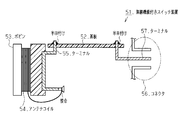
- the antenna coil 4 is wound around the body 3 around the knob 2. Further, both the first coil terminal 5 and the second coil terminal 6 are insert-molded in the body 3. In the body 3, a frame-like connector housing 7 is set at an intermediate position between the first coil terminal 5 and the second coil terminal 6.
- the first end of the first coil terminal 5 protrudes from the body 3 outside the frame of the connector housing 7 (left side of the paper).
- the first end of the antenna coil 4 is wound around the tip of the protruding portion, and both are joined by caulking or the like.
- the second end of the first coil terminal 5 protrudes from the body 3 within the frame of the connector housing 7.
- the tip of the protruding portion is defined as the connector terminal 8.
- the first end of the second coil terminal 6 protrudes from the body 3 outside the frame of the connector housing 7 on the opposite side to the first end of the first coil terminal 5 (right side of the drawing). Near the tip of the protruding portion, the second end of the antenna coil 4 is wound, and both are joined by caulking or the like.
- the second end of the second coil terminal 6 protrudes from the body 3 within the frame of the connector housing 7.
- the tip of the protruding portion is defined as a connector terminal (not shown) at the back of the page.
- the substrate 3 is assembled with a board 9 on which required parts are mounted.
- the mounted parts also exchange electrical signals between the push start switch 1 and an external device.
- a pin header 10 is included which is defined as a connection medium that enables the connection.
- the pin header 10 includes a case 11 that functions as a mother body and a plurality of pins 12 that protrude from the case 11 in an aligned state.
- a positioning hole 13 that is slightly smaller than the frame of the connector housing 7 is formed in the frame of the connector housing 7, and the pin header 10 is positioned by the positioning hole 13. That is, when the board 9 on which the pin header 10 or the like is mounted is attached to the body 3, the pin header 10 is engaged with the positioning hole 13. At this time, the case 11 is brought into contact with the wall of the body 3 that defines the positioning hole 13. Thereby, the front-end
- a connector in which a plurality of connector terminals (including the connector terminals 8 and the pins 12) are arranged in an aligned state within the frame of the connector housing 7 is configured.
- Push start switch 1 Body 3
- a knob 2 assembled to the body 3 and capable of operating a switch;
- the connector terminal 8 is provided by insert molding on the body 3 and is joined to the antenna coil 4 with at least one terminal 5, 6; And at least one pin 12.
- the knob 2 includes an operation surface 2a that can be operated by a user, Body 3 A body housing 3a for accommodating the knob 2 so that the operation surface 2a of the knob 2 is exposed from the body 3, An outer peripheral surface 3b of the body 3 provided at a position corresponding to the outer peripheral surface 2b of the knob 2, It is preferable to include a winding portion 3c that is formed on the outer peripheral surface 3b of the body 3 and on which the antenna coil 4 is wound.
- Push start switch 1 of the concept 1, at least one of the terminals 5 and 6 is A first end 5a, 6a protruding from the body 3 and joined to the antenna coil 4; The second ends 5b and 6b projecting from the body 3 located in the vicinity of at least one pin 12 than the first ends 5a and 6a, Push start switch 1 Preferably, it further comprises a connector housing 7 surrounding the second ends 5b, 6b of the at least one terminal 5, 6 and at least one pin 12.
- the body 3 has an outer surface 3c opposite to the body housing 3a,
- the second ends 5 b, 6 b of the at least one terminal 5, 6 and the at least one pin 12 preferably protrude from the outer surface 3 c of the body 3.
- the body 3 has a positioning hole 13 that penetrates the outer surface 3c and the inner surface 3d facing the outer surface 3c, Push start switch 1 It is preferable to include a holding portion 11 that is fitted into the positioning hole 13 of the body 3 and holds at least one pin 12.
- a connector housing 7 is formed on the body 3 around which the antenna coil 4 is wound, and the first coil terminal 5 and the second coil terminal 6 which are insert-molded on the body 3 function as connector terminals 8 and the like. That is, of the connector elements, both the connector terminal 8 and the connector housing 7 are defined by a single component (body 3). Thereby, it becomes easy to satisfy the dimensional accuracy required for the connector.
- a pin header 10 which is a separate part from the body 3 is positioned by the body 3. Thereby, even when the pin header 10 is a connector element, the connector alignment is easily satisfied.
- the first coil terminal 5 and the second coil terminal 6 which are insert-molded on the body 3 function as connector terminals 8, and the connector is constituted by the connector terminals 8 and the connector housing 7 defined in the body 3. Is done. Thus, soldering is not performed when the connector is configured. For this reason, with the abolition of soldering, an inexpensive and small switch device with a wireless function can be provided.
- the connector terminal includes a plurality of pins 12 of the pin header 10, the first coil terminal 5 and the second coil terminal 6, and a positioning hole 13 for positioning the pin header 10 in the connector housing 7 is provided.
- Body 3 is set. According to this configuration, the connector alignment can be satisfied by selecting the pin header 10 that conforms to the connector specifications (pin arrangement or the like) and positioning the pin header 10.
- the first embodiment can be modified and embodied as follows.
- the present technology may be applied not only to a switch device with a wireless function such as the push start switch 1 but also to switch devices that can perform a switch operation using the knob 2.
- a terminal first coil terminal 5 or the like
- a connector housing 7 defined around the terminal of the body 3.
- the present technology may be applied to a configuration in which a connector is configured. In this case, not only the antenna coil 4 but also a switch component is joined to the terminal.
- the terminal insert-molded in the body 3 becomes the connector terminal, and the connector is configured together with the connector housing 7 defined in the body 3. And this does not involve soldering. Therefore, with the abolition of soldering, an inexpensive and small switch device can be provided.
- positioning means for positioning another part (pin header 10 or the like) provided with pins constituting the connector terminal together with the terminal within the connector housing 7 is set in the body 3 Is desirable.
- the present technology may be applied to all antenna devices that can perform communication operation using the antenna coil 4. That is, in the antenna device, the antenna coil 4 is wound around the body 3 and a terminal (the first coil terminal 5 or the like) to which the antenna coil 4 is joined is insert-molded on the body 3.
- the present technology may be applied to a connector that includes both the terminal and the connector housing 7 defined around the terminal of the body 3. In this case, the knob 2 is selectively assembled to the body 3 according to the presence or absence of the switch operation.
- the terminal insert-molded in the body 3 becomes the connector terminal, and the connector is configured together with the connector housing 7 defined in the body 3. And this does not involve soldering. Therefore, with the abolition of soldering, an inexpensive and small antenna device can be provided.
- positioning means for positioning another part (pin header 10 or the like) provided with pins constituting the connector terminal together with the terminal in the connector housing 7 is set in the body 3. It is desirable.
- connector alignment can be satisfied by selecting another part that conforms to the specifications of the connector and positioning the other part.
- the present technology may be applied to all connector devices that can be connected to external devices.
- a terminal first coil terminal 5 or the like
- the terminal and the connector housing 7 defined around the terminal of the body 3.
- a connector is configured including both.
- a positioning means positioning hole 13 or the like
- the antenna coil 4 is selectively wound around the body 3 according to the presence / absence of a communication operation
- the knob 2 is selectively assembled according to the presence / absence of a switch operation.
- connector alignment can be satisfied by selecting another part that conforms to the specifications of the connector and positioning the other part.
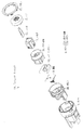
- the body 3 is constituted by both the body main body 3A and the bobbin 3B, and the knob 2 is assembled to the body 3.
- An antenna coil (not shown) similar to the antenna coil 4 of the first embodiment is wound around the bobbin 3B.
- a bezel 15 which is a decorative article is provided.
- the knob 2 incorporates a lens 16 made of a translucent member for the purpose of guiding the light of the light emitting diode on the substrate 9.
- the lens 16 is supported by a holder 17.
- a rubber contact 18 that functions as a movable contact in the switch operation of the knob 2 is incorporated in the body 3.
- both the substrate 9 and the rubber contact 18 are temporarily placed through the side opening of the bobbin 3B.
- the body 3A is assembled through the upper opening of the bobbin 3B with the holder 17, the lens 16, and the knob 2 attached.
- the bobbin 3B is covered with a cover 19 separate from the body 3 from below, and in the process, the bobbin 3B is positioned together with the substrate 9 and the rubber contact 18 in the temporarily placed state.
- the bezel 15 is assembled to the cover 19.
- the first coil terminal 5A and the second coil terminal 6A similar to the first coil terminal 5 and the second coil terminal 6 of the first embodiment are inserted into the bobbin 3B. Molded. As in the first embodiment, the first end of the first coil terminal 5A is joined to the first end of the antenna coil, and the second end of the first coil terminal 5A is connected to the connector terminal 8A. It is prescribed. Similarly, the second end of the antenna coil is joined to the first end of the second coil terminal 6A, and the second end of the second coil terminal 6A is defined as the connector terminal 8B. A pair of positioning holes 20 are formed at the bottom of the bobbin 3B.
- a pin header 21 is mounted on the lower surface of the substrate 9.
- the pin header 21 includes a main body portion 22 that functions as a mother body and a plurality of pins 23 that protrude from the main body portion 22 in an aligned state.
- the base end portion of each pin 23 is fixed (electrically connected) to the substrate 9, and the tip end portion of each pin 23 functions as a connector terminal.
- the height of each connector terminal (connector terminal 8A, connector terminal 8B, each pin 23) (the amount of protrusion from the substrate 9) is aligned.
- a pair of positioning holes 24 corresponding to the positioning holes 20 of the bobbin 3B are formed in the main body portion 22 of the pin header 21.
- a frame-shaped connector housing 25 is defined around each connector terminal (pin 23 and the like) in the cover 19.
- the connector has a plurality of connector terminals (connector terminals 8A, connector terminals 8B, and pins 23) arranged in an aligned state.
- the communication operation by the antenna coil and the switch operation by the knob 2 are reflected in the vehicle control.
- two positioning projections 26 corresponding to the positioning hole 20 of the bobbin 3B and the positioning hole 24 of the pin header 21 are formed on the inner bottom surface of the cover 19, respectively.
- the two positioning projections 26 of the cover 19 are mounted on the positioning hole 20 of the bobbin 3B and the substrate 9 in the temporarily placed state. Are inserted into the positioning holes 24 respectively. Accordingly, the bobbin 3B is positioned together with the temporarily placed substrate 9 and the rubber contact 18.
- the first coil terminal 5 ⁇ / b> A and the second coil terminal 6 ⁇ / b> A that are insert-molded on the bobbin 3 ⁇ / b> B together with the pins 23 of the pin header 21 constitute a connector terminal. And this does not involve soldering. Therefore, with the abolition of soldering, an inexpensive and small push start switch 1A can be provided.
- the first coil terminal 5A and the second coil terminal 6A that are insert-molded on the bobbin 3B become connector terminals together with the pins 23 of the pin header 21, and the connector defined in the cover 19 separate from the body 3 A connector is configured together with the housing 25. And this does not involve soldering. Therefore, with the abolition of soldering, an inexpensive and small push start switch 1A can be provided.
- a positioning projection 26 for positioning the pin header 21 provided with each pin 23 constituting the connector terminal together with the bobbin 3B is set on the cover 19. According to this configuration, connector alignment can be satisfied by selecting the pin header 21 that conforms to the connector specifications (pin arrangement and the like) and positioning the pin header 21.
- the second embodiment may be modified and embodied as follows.
- the present technology may be applied to all of the switch device, the antenna device, and the connector device.
Abstract
L'invention porte sur un appareil de commutation ayant une fonction sans fil, qui comporte : un corps (3); un bouton (2), qui est assemblé au corps (3), et qui peut être actionné par commutation ; une bobine d'antenne (4) pour des opérations de communication, ladite bobine d'antenne étant enroulée sur le corps (3) ; et une borne de connecteur (8). La borne de connecteur (8) comprend : au moins une borne (5, 6), qui est disposée sur le corps (3) par moulage par insertion, et qui est liée à la bobine d'antenne (4) ; et au moins une broche (12).
Priority Applications (3)
| Application Number | Priority Date | Filing Date | Title |
|---|---|---|---|
| EP15761921.4A EP3118876B1 (fr) | 2014-03-11 | 2015-03-05 | Appareil de commutation ayant une fonction sans fil |
| CN201580012590.2A CN106104733B (zh) | 2014-03-11 | 2015-03-05 | 带有无线功能的开关装置 |
| US15/123,677 US10157715B2 (en) | 2014-03-11 | 2015-03-05 | Switch apparatus having wireless function |
Applications Claiming Priority (4)
| Application Number | Priority Date | Filing Date | Title |
|---|---|---|---|
| JP2014-047685 | 2014-03-11 | ||
| JP2014047685 | 2014-03-11 | ||
| JP2014220468A JP5866425B2 (ja) | 2014-03-11 | 2014-10-29 | 無線機能付きスイッチ装置 |
| JP2014-220468 | 2014-10-29 |
Publications (1)
| Publication Number | Publication Date |
|---|---|
| WO2015137239A1 true WO2015137239A1 (fr) | 2015-09-17 |
Family
ID=54071685
Family Applications (1)
| Application Number | Title | Priority Date | Filing Date |
|---|---|---|---|
| PCT/JP2015/056564 WO2015137239A1 (fr) | 2014-03-11 | 2015-03-05 | Appareil de commutation ayant une fonction sans fil |
Country Status (5)
| Country | Link |
|---|---|
| US (1) | US10157715B2 (fr) |
| EP (1) | EP3118876B1 (fr) |
| JP (1) | JP5866425B2 (fr) |
| CN (1) | CN106104733B (fr) |
| WO (1) | WO2015137239A1 (fr) |
Families Citing this family (3)
| Publication number | Priority date | Publication date | Assignee | Title |
|---|---|---|---|---|
| JP6893692B2 (ja) * | 2016-12-27 | 2021-06-23 | 帝国通信工業株式会社 | 端子ユニット及び端子ユニット付きケース |
| JP7058734B2 (ja) | 2018-06-26 | 2022-04-22 | アルプスアルパイン株式会社 | エンジンスタート装置及びその製造方法 |
| CN111446096A (zh) * | 2020-03-11 | 2020-07-24 | 法雷奥舒适驾驶辅助系统(广州)有限公司 | 一种带天线的紧凑型汽车启动开关 |
Citations (2)
| Publication number | Priority date | Publication date | Assignee | Title |
|---|---|---|---|---|
| JP2012116422A (ja) * | 2010-12-03 | 2012-06-21 | Tokai Rika Co Ltd | 無線機能付きスイッチ装置 |
| JP2014167260A (ja) * | 2013-02-28 | 2014-09-11 | Yuhshin Co Ltd | スイッチ装置 |
Family Cites Families (7)
| Publication number | Priority date | Publication date | Assignee | Title |
|---|---|---|---|---|
| JP2005057131A (ja) * | 2003-08-06 | 2005-03-03 | Matsushita Electric Works Ltd | コイルボビン |
| JP5038267B2 (ja) | 2008-09-01 | 2012-10-03 | 株式会社東海理化電機製作所 | エンジンスタータースイッチ装置 |
| JP2011027085A (ja) * | 2009-07-29 | 2011-02-10 | Honda Lock Mfg Co Ltd | エンジンのスタート・ストップスイッチ装置 |
| JP5471214B2 (ja) | 2009-09-11 | 2014-04-16 | パナソニック株式会社 | スイッチ装置 |
| JP5317943B2 (ja) * | 2009-12-09 | 2013-10-16 | アルプス電気株式会社 | スイッチ装置 |
| JP5649829B2 (ja) * | 2010-02-17 | 2015-01-07 | 株式会社ユーシン | スイッチ装置 |
| JP6230536B2 (ja) * | 2012-07-25 | 2017-11-15 | 株式会社ユーシン | スイッチ装置 |
-
2014
- 2014-10-29 JP JP2014220468A patent/JP5866425B2/ja active Active
-
2015
- 2015-03-05 US US15/123,677 patent/US10157715B2/en active Active
- 2015-03-05 CN CN201580012590.2A patent/CN106104733B/zh active Active
- 2015-03-05 WO PCT/JP2015/056564 patent/WO2015137239A1/fr active Application Filing
- 2015-03-05 EP EP15761921.4A patent/EP3118876B1/fr active Active
Patent Citations (2)
| Publication number | Priority date | Publication date | Assignee | Title |
|---|---|---|---|---|
| JP2012116422A (ja) * | 2010-12-03 | 2012-06-21 | Tokai Rika Co Ltd | 無線機能付きスイッチ装置 |
| JP2014167260A (ja) * | 2013-02-28 | 2014-09-11 | Yuhshin Co Ltd | スイッチ装置 |
Also Published As
| Publication number | Publication date |
|---|---|
| EP3118876B1 (fr) | 2020-01-01 |
| JP2015187968A (ja) | 2015-10-29 |
| EP3118876A4 (fr) | 2017-11-01 |
| CN106104733A (zh) | 2016-11-09 |
| EP3118876A1 (fr) | 2017-01-18 |
| JP5866425B2 (ja) | 2016-02-17 |
| US20170018377A1 (en) | 2017-01-19 |
| US10157715B2 (en) | 2018-12-18 |
| CN106104733B (zh) | 2019-03-22 |
Similar Documents
| Publication | Publication Date | Title |
|---|---|---|
| JP5471214B2 (ja) | スイッチ装置 | |
| WO2014017324A1 (fr) | Dispositif de commutation | |
| WO2011013465A1 (fr) | Dispositif de commutation pour le démarrage/larrêt dun moteur | |
| JP5749754B2 (ja) | スイッチ装置 | |
| JP5649829B2 (ja) | スイッチ装置 | |
| JP5444075B2 (ja) | スイッチ装置 | |
| WO2015137239A1 (fr) | Appareil de commutation ayant une fonction sans fil | |
| JP6017348B2 (ja) | スイッチ装置 | |
| JP4079017B2 (ja) | リモコン送信機 | |
| JP5361462B2 (ja) | スイッチ装置、並びに、制御システム | |
| JP5317943B2 (ja) | スイッチ装置 | |
| CN112219252B (zh) | 发动机起动装置及其制造方法 | |
| KR101707280B1 (ko) | 스위치 장치 및 스위치 장치의 조립 방법 | |
| JP5502975B2 (ja) | エンジンのスタート・ストップスイッチ装置 | |
| JP6132432B2 (ja) | アンテナ装置 | |
| JP2005174628A (ja) | 電池収容器及びこれを用いたリモコン送信機 | |
| JP6017349B2 (ja) | スイッチ装置 | |
| JPH0932384A (ja) | 車両用キー装置 | |
| WO2016088642A1 (fr) | Clé électronique | |
| JP2023091909A (ja) | スイッチ装置 | |
| JP5827154B2 (ja) | 電気機器 | |
| KR20170018255A (ko) | 차량용 버튼 시동 스위치 장치 |
Legal Events
| Date | Code | Title | Description |
|---|---|---|---|
| 121 | Ep: the epo has been informed by wipo that ep was designated in this application |
Ref document number: 15761921 Country of ref document: EP Kind code of ref document: A1 |
|
| WWE | Wipo information: entry into national phase |
Ref document number: 15123677 Country of ref document: US |
|
| REEP | Request for entry into the european phase |
Ref document number: 2015761921 Country of ref document: EP |
|
| WWE | Wipo information: entry into national phase |
Ref document number: 2015761921 Country of ref document: EP |
|
| NENP | Non-entry into the national phase |
Ref country code: DE |