WO2015137239A1 - Switch apparatus having wireless function - Google Patents
Switch apparatus having wireless function Download PDFInfo
- Publication number
- WO2015137239A1 WO2015137239A1 PCT/JP2015/056564 JP2015056564W WO2015137239A1 WO 2015137239 A1 WO2015137239 A1 WO 2015137239A1 JP 2015056564 W JP2015056564 W JP 2015056564W WO 2015137239 A1 WO2015137239 A1 WO 2015137239A1
- Authority
- WO
- WIPO (PCT)
- Prior art keywords
- terminal
- connector
- switch device
- wireless function
- pin
- Prior art date
Links
Images


Classifications
-
- H—ELECTRICITY
- H01—ELECTRIC ELEMENTS
- H01H—ELECTRIC SWITCHES; RELAYS; SELECTORS; EMERGENCY PROTECTIVE DEVICES
- H01H9/00—Details of switching devices, not covered by groups H01H1/00 - H01H7/00
- H01H9/16—Indicators for switching condition, e.g. "on" or "off"
- H01H9/168—Indicators for switching condition, e.g. "on" or "off" making use of an electromagnetic wave communication
-
- H—ELECTRICITY
- H01—ELECTRIC ELEMENTS
- H01H—ELECTRIC SWITCHES; RELAYS; SELECTORS; EMERGENCY PROTECTIVE DEVICES
- H01H13/00—Switches having rectilinearly-movable operating part or parts adapted for pushing or pulling in one direction only, e.g. push-button switch
- H01H13/02—Details
- H01H13/023—Light-emitting indicators
-
- H—ELECTRICITY
- H01—ELECTRIC ELEMENTS
- H01H—ELECTRIC SWITCHES; RELAYS; SELECTORS; EMERGENCY PROTECTIVE DEVICES
- H01H13/00—Switches having rectilinearly-movable operating part or parts adapted for pushing or pulling in one direction only, e.g. push-button switch
- H01H13/02—Details
- H01H13/04—Cases; Covers
-
- H—ELECTRICITY
- H01—ELECTRIC ELEMENTS
- H01H—ELECTRIC SWITCHES; RELAYS; SELECTORS; EMERGENCY PROTECTIVE DEVICES
- H01H13/00—Switches having rectilinearly-movable operating part or parts adapted for pushing or pulling in one direction only, e.g. push-button switch
- H01H13/50—Switches having rectilinearly-movable operating part or parts adapted for pushing or pulling in one direction only, e.g. push-button switch having a single operating member
- H01H13/52—Switches having rectilinearly-movable operating part or parts adapted for pushing or pulling in one direction only, e.g. push-button switch having a single operating member the contact returning to its original state immediately upon removal of operating force, e.g. bell-push switch
-
- H—ELECTRICITY
- H01—ELECTRIC ELEMENTS
- H01Q—ANTENNAS, i.e. RADIO AERIALS
- H01Q1/00—Details of, or arrangements associated with, antennas
- H01Q1/27—Adaptation for use in or on movable bodies
- H01Q1/32—Adaptation for use in or on road or rail vehicles
- H01Q1/3208—Adaptation for use in or on road or rail vehicles characterised by the application wherein the antenna is used
- H01Q1/3233—Adaptation for use in or on road or rail vehicles characterised by the application wherein the antenna is used particular used as part of a sensor or in a security system, e.g. for automotive radar, navigation systems
- H01Q1/3241—Adaptation for use in or on road or rail vehicles characterised by the application wherein the antenna is used particular used as part of a sensor or in a security system, e.g. for automotive radar, navigation systems particular used in keyless entry systems
-
- H—ELECTRICITY
- H01—ELECTRIC ELEMENTS
- H01Q—ANTENNAS, i.e. RADIO AERIALS
- H01Q7/00—Loop antennas with a substantially uniform current distribution around the loop and having a directional radiation pattern in a plane perpendicular to the plane of the loop
-
- B—PERFORMING OPERATIONS; TRANSPORTING
- B60—VEHICLES IN GENERAL
- B60R—VEHICLES, VEHICLE FITTINGS, OR VEHICLE PARTS, NOT OTHERWISE PROVIDED FOR
- B60R25/00—Fittings or systems for preventing or indicating unauthorised use or theft of vehicles
- B60R25/20—Means to switch the anti-theft system on or off
- B60R25/24—Means to switch the anti-theft system on or off using electronic identifiers containing a code not memorised by the user
-
- H—ELECTRICITY
- H01—ELECTRIC ELEMENTS
- H01H—ELECTRIC SWITCHES; RELAYS; SELECTORS; EMERGENCY PROTECTIVE DEVICES
- H01H2231/00—Applications
- H01H2231/026—Car
-
- H—ELECTRICITY
- H01—ELECTRIC ELEMENTS
- H01H—ELECTRIC SWITCHES; RELAYS; SELECTORS; EMERGENCY PROTECTIVE DEVICES
- H01H2300/00—Orthogonal indexing scheme relating to electric switches, relays, selectors or emergency protective devices covered by H01H
- H01H2300/03—Application domotique, e.g. for house automation, bus connected switches, sensors, loads or intelligent wiring
- H01H2300/032—Application domotique, e.g. for house automation, bus connected switches, sensors, loads or intelligent wiring using RFID technology in switching devices
Definitions
- the present invention relates to a switch device with a wireless function capable of communication operation by an antenna coil and switch operation by a knob.
- Patent Document 1 discloses a switch device used in an engine start system for a vehicle.
- a user of a vehicle applied to the above system has an electronic key (referred to as a portable device) instead of a conventional mechanical key.
- the vehicle collates the electronic key, and permits vehicle control such as engine starting when it is positively determined that the electronic key is a key of the vehicle.
- the portable device has a built-in battery and transmits a unique ID (identification) to the own device in response to a request signal from the vehicle.
- the vehicle determines whether the ID acquired from the portable device matches the reference ID, and allows vehicle control on condition that the ID acquired from the portable device matches the reference ID. Therefore, the engine can be started by operating the knob of the switch device installed near the driver's seat while the user carries the portable device.
- the portable device cannot transmit the ID in response to the request signal. That is, in this case, the user cannot start the engine even if the user operates the knob of the switch device while holding the portable device.
- an antenna coil is provided in the switch device in order to cope with a situation such as battery exhaustion. Drive radio waves are transmitted from the antenna coil when the knob of the switch device is operated.
- the portable device enters the transmission area of the driving radio wave, the portable device generates power from the driving radio wave and transmits an ID based on the generated power. Therefore, the engine can be started by operating the knob of the switch device while the user holds the portable device over the switch device.
- a switch device capable of performing a communication operation using an antenna coil and a switch operation using a knob suitable for the above countermeasure is defined as a switch device with a wireless function.
- the switch device 51 with a wireless function includes a case (not shown), and a substrate 52 on which necessary components are mounted is accommodated in the case.
- the mounting component of the substrate 52 includes an antenna unit.
- the antenna unit includes a bobbin 53, an antenna coil 54 wound around the bobbin 53, and a terminal 55 provided on the bobbin 53.
- Terminal 55 includes a first end and a second end protruding from bobbin 53.
- the end of the antenna coil 54 is wound around the tip of the first end of the terminal 55, and both are joined by caulking or the like.
- the tip of the second end of the terminal 55 is inserted into the hole of the substrate 52.
- the portion that has passed through the hole at the second end of the terminal 55 is soldered on the upper surface of the substrate 52.
- a terminal 57 of a connector 56 which is one of the mounted components, is soldered to a location different from the location where the terminal 55 is soldered on the substrate 52.
- the terminal 57 of the connector 56 is electrically connected to the terminal 55 of the antenna coil 54 through the conductive pattern of the substrate 52.
- the connector 56 is provided with another terminal serving as a medium for outputting a switch signal or the like accompanying operation of a knob (not shown) to an external device.
- the terminal 55 of the antenna coil 54 is soldered to the substrate 52, and the terminal 55 of the antenna coil 54 is electrically connected to the terminal 57 of the connector 56 via the substrate 52.
- a process for soldering the terminal 55 is required, and a space for soldering the terminal 55 is required on the substrate 52. This causes an increase in cost and size of the wireless function switch device 51.
- the present invention has been made paying attention to such problems, and an object of the present invention is to provide a switch device with a wireless function that is inexpensive and can be miniaturized.
- One aspect of the present invention is a switch device with a wireless function, which is a body, a knob that is assembled to the body and can be operated by a switch, an antenna coil for communication operation wound around the body, a connector terminal,
- the connector terminal includes at least one terminal provided on the body by insert molding and joined to the antenna coil, and at least one pin.
- the said structure WHEREIN It is preferable to provide the cover which is provided so that the said connector terminal may be enclosed, and prescribes
- a holding portion that holds the at least one pin it is preferable that a holding portion that holds the at least one pin is provided, and the cover includes a positioning portion that positions the holding portion and the body.
- a switch device with a wireless function which is a body, a knob assembled to the body and capable of operating a switch, an antenna coil for communication operation wound around the body, and a connector
- the connector includes at least one terminal that is provided on the body by insert molding and is joined to the antenna coil, and a housing that surrounds the at least one terminal.
- the connector includes a connector terminal having the at least one terminal and at least one pin
- the switch device with a wireless function includes a holding unit that holds the at least one pin
- the body includes: It is preferable that a positioning part for positioning the holding part in the housing is included.
- the knob includes an operation surface operable by a user
- the body includes a body housing that accommodates the knob so that the operation surface of the knob is exposed from the body, and an outer peripheral surface of the knob. It is preferable that the outer peripheral surface of the body provided in the corresponding position and the winding part formed in the outer peripheral surface of the said body for the said antenna coil to wind are included.
- the at least one terminal protrudes from the body and is joined to the antenna coil, and the body is located closer to the at least one pin than the first end.
- the wireless function switch device further includes a connector housing surrounding the second end of the at least one terminal and the at least one pin.
- the body has an outer surface opposite to the body housing, and the second end of the at least one terminal and the at least one pin protrude from the outer surface of the body. Is preferred.
- the said connector housing is integrally formed with the said body.
- the connector housing includes a cover that is attached to the body and accommodates the first end and the second end of the at least one terminal and the at least one pin.
- the body has a positioning hole that penetrates the outer surface and an inner surface facing the outer surface, and the switch device with a wireless function is fitted into the positioning hole of the body, and the at least It is preferable to provide a holding part for holding one pin.
- Sectional drawing which shows the structure of the push start switch of 1st Embodiment.
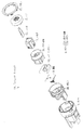
- the disassembled perspective view which shows the structure of the push start switch of 2nd Embodiment.
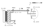
- Sectional drawing of the principal part of a push start switch Sectional drawing which shows the structure of the conventional switch apparatus with a wireless function.
- a push start switch 1 that is an example of a switch device with a wireless function is installed near a driver's seat.
- the push start switch 1 includes a body 3 and a knob 2 that is assembled to the body 3 and is exposed from the body 3 and can be operated by a user.
- An engine start system is applied to a vehicle on which the push start switch 1 is mounted, and the user has a portable device as a vehicle key.
- the antenna coil 4 is wound around the body 3 around the knob 2. Further, both the first coil terminal 5 and the second coil terminal 6 are insert-molded in the body 3. In the body 3, a frame-like connector housing 7 is set at an intermediate position between the first coil terminal 5 and the second coil terminal 6.
- the first end of the first coil terminal 5 protrudes from the body 3 outside the frame of the connector housing 7 (left side of the paper).
- the first end of the antenna coil 4 is wound around the tip of the protruding portion, and both are joined by caulking or the like.
- the second end of the first coil terminal 5 protrudes from the body 3 within the frame of the connector housing 7.
- the tip of the protruding portion is defined as the connector terminal 8.
- the first end of the second coil terminal 6 protrudes from the body 3 outside the frame of the connector housing 7 on the opposite side to the first end of the first coil terminal 5 (right side of the drawing). Near the tip of the protruding portion, the second end of the antenna coil 4 is wound, and both are joined by caulking or the like.
- the second end of the second coil terminal 6 protrudes from the body 3 within the frame of the connector housing 7.
- the tip of the protruding portion is defined as a connector terminal (not shown) at the back of the page.
- the substrate 3 is assembled with a board 9 on which required parts are mounted.
- the mounted parts also exchange electrical signals between the push start switch 1 and an external device.
- a pin header 10 is included which is defined as a connection medium that enables the connection.
- the pin header 10 includes a case 11 that functions as a mother body and a plurality of pins 12 that protrude from the case 11 in an aligned state.
- a positioning hole 13 that is slightly smaller than the frame of the connector housing 7 is formed in the frame of the connector housing 7, and the pin header 10 is positioned by the positioning hole 13. That is, when the board 9 on which the pin header 10 or the like is mounted is attached to the body 3, the pin header 10 is engaged with the positioning hole 13. At this time, the case 11 is brought into contact with the wall of the body 3 that defines the positioning hole 13. Thereby, the front-end
- a connector in which a plurality of connector terminals (including the connector terminals 8 and the pins 12) are arranged in an aligned state within the frame of the connector housing 7 is configured.
- Push start switch 1 Body 3
- a knob 2 assembled to the body 3 and capable of operating a switch;
- the connector terminal 8 is provided by insert molding on the body 3 and is joined to the antenna coil 4 with at least one terminal 5, 6; And at least one pin 12.
- the knob 2 includes an operation surface 2a that can be operated by a user, Body 3 A body housing 3a for accommodating the knob 2 so that the operation surface 2a of the knob 2 is exposed from the body 3, An outer peripheral surface 3b of the body 3 provided at a position corresponding to the outer peripheral surface 2b of the knob 2, It is preferable to include a winding portion 3c that is formed on the outer peripheral surface 3b of the body 3 and on which the antenna coil 4 is wound.
- Push start switch 1 of the concept 1, at least one of the terminals 5 and 6 is A first end 5a, 6a protruding from the body 3 and joined to the antenna coil 4; The second ends 5b and 6b projecting from the body 3 located in the vicinity of at least one pin 12 than the first ends 5a and 6a, Push start switch 1 Preferably, it further comprises a connector housing 7 surrounding the second ends 5b, 6b of the at least one terminal 5, 6 and at least one pin 12.
- the body 3 has an outer surface 3c opposite to the body housing 3a,
- the second ends 5 b, 6 b of the at least one terminal 5, 6 and the at least one pin 12 preferably protrude from the outer surface 3 c of the body 3.
- the body 3 has a positioning hole 13 that penetrates the outer surface 3c and the inner surface 3d facing the outer surface 3c, Push start switch 1 It is preferable to include a holding portion 11 that is fitted into the positioning hole 13 of the body 3 and holds at least one pin 12.
- a connector housing 7 is formed on the body 3 around which the antenna coil 4 is wound, and the first coil terminal 5 and the second coil terminal 6 which are insert-molded on the body 3 function as connector terminals 8 and the like. That is, of the connector elements, both the connector terminal 8 and the connector housing 7 are defined by a single component (body 3). Thereby, it becomes easy to satisfy the dimensional accuracy required for the connector.
- a pin header 10 which is a separate part from the body 3 is positioned by the body 3. Thereby, even when the pin header 10 is a connector element, the connector alignment is easily satisfied.
- the first coil terminal 5 and the second coil terminal 6 which are insert-molded on the body 3 function as connector terminals 8, and the connector is constituted by the connector terminals 8 and the connector housing 7 defined in the body 3. Is done. Thus, soldering is not performed when the connector is configured. For this reason, with the abolition of soldering, an inexpensive and small switch device with a wireless function can be provided.
- the connector terminal includes a plurality of pins 12 of the pin header 10, the first coil terminal 5 and the second coil terminal 6, and a positioning hole 13 for positioning the pin header 10 in the connector housing 7 is provided.
- Body 3 is set. According to this configuration, the connector alignment can be satisfied by selecting the pin header 10 that conforms to the connector specifications (pin arrangement or the like) and positioning the pin header 10.
- the first embodiment can be modified and embodied as follows.
- the present technology may be applied not only to a switch device with a wireless function such as the push start switch 1 but also to switch devices that can perform a switch operation using the knob 2.
- a terminal first coil terminal 5 or the like
- a connector housing 7 defined around the terminal of the body 3.
- the present technology may be applied to a configuration in which a connector is configured. In this case, not only the antenna coil 4 but also a switch component is joined to the terminal.
- the terminal insert-molded in the body 3 becomes the connector terminal, and the connector is configured together with the connector housing 7 defined in the body 3. And this does not involve soldering. Therefore, with the abolition of soldering, an inexpensive and small switch device can be provided.
- positioning means for positioning another part (pin header 10 or the like) provided with pins constituting the connector terminal together with the terminal within the connector housing 7 is set in the body 3 Is desirable.
- the present technology may be applied to all antenna devices that can perform communication operation using the antenna coil 4. That is, in the antenna device, the antenna coil 4 is wound around the body 3 and a terminal (the first coil terminal 5 or the like) to which the antenna coil 4 is joined is insert-molded on the body 3.
- the present technology may be applied to a connector that includes both the terminal and the connector housing 7 defined around the terminal of the body 3. In this case, the knob 2 is selectively assembled to the body 3 according to the presence or absence of the switch operation.
- the terminal insert-molded in the body 3 becomes the connector terminal, and the connector is configured together with the connector housing 7 defined in the body 3. And this does not involve soldering. Therefore, with the abolition of soldering, an inexpensive and small antenna device can be provided.
- positioning means for positioning another part (pin header 10 or the like) provided with pins constituting the connector terminal together with the terminal in the connector housing 7 is set in the body 3. It is desirable.
- connector alignment can be satisfied by selecting another part that conforms to the specifications of the connector and positioning the other part.
- the present technology may be applied to all connector devices that can be connected to external devices.
- a terminal first coil terminal 5 or the like
- the terminal and the connector housing 7 defined around the terminal of the body 3.
- a connector is configured including both.
- a positioning means positioning hole 13 or the like
- the antenna coil 4 is selectively wound around the body 3 according to the presence / absence of a communication operation
- the knob 2 is selectively assembled according to the presence / absence of a switch operation.
- connector alignment can be satisfied by selecting another part that conforms to the specifications of the connector and positioning the other part.
- the body 3 is constituted by both the body main body 3A and the bobbin 3B, and the knob 2 is assembled to the body 3.
- An antenna coil (not shown) similar to the antenna coil 4 of the first embodiment is wound around the bobbin 3B.
- a bezel 15 which is a decorative article is provided.
- the knob 2 incorporates a lens 16 made of a translucent member for the purpose of guiding the light of the light emitting diode on the substrate 9.
- the lens 16 is supported by a holder 17.
- a rubber contact 18 that functions as a movable contact in the switch operation of the knob 2 is incorporated in the body 3.
- both the substrate 9 and the rubber contact 18 are temporarily placed through the side opening of the bobbin 3B.
- the body 3A is assembled through the upper opening of the bobbin 3B with the holder 17, the lens 16, and the knob 2 attached.
- the bobbin 3B is covered with a cover 19 separate from the body 3 from below, and in the process, the bobbin 3B is positioned together with the substrate 9 and the rubber contact 18 in the temporarily placed state.
- the bezel 15 is assembled to the cover 19.
- the first coil terminal 5A and the second coil terminal 6A similar to the first coil terminal 5 and the second coil terminal 6 of the first embodiment are inserted into the bobbin 3B. Molded. As in the first embodiment, the first end of the first coil terminal 5A is joined to the first end of the antenna coil, and the second end of the first coil terminal 5A is connected to the connector terminal 8A. It is prescribed. Similarly, the second end of the antenna coil is joined to the first end of the second coil terminal 6A, and the second end of the second coil terminal 6A is defined as the connector terminal 8B. A pair of positioning holes 20 are formed at the bottom of the bobbin 3B.
- a pin header 21 is mounted on the lower surface of the substrate 9.
- the pin header 21 includes a main body portion 22 that functions as a mother body and a plurality of pins 23 that protrude from the main body portion 22 in an aligned state.
- the base end portion of each pin 23 is fixed (electrically connected) to the substrate 9, and the tip end portion of each pin 23 functions as a connector terminal.
- the height of each connector terminal (connector terminal 8A, connector terminal 8B, each pin 23) (the amount of protrusion from the substrate 9) is aligned.
- a pair of positioning holes 24 corresponding to the positioning holes 20 of the bobbin 3B are formed in the main body portion 22 of the pin header 21.
- a frame-shaped connector housing 25 is defined around each connector terminal (pin 23 and the like) in the cover 19.
- the connector has a plurality of connector terminals (connector terminals 8A, connector terminals 8B, and pins 23) arranged in an aligned state.
- the communication operation by the antenna coil and the switch operation by the knob 2 are reflected in the vehicle control.
- two positioning projections 26 corresponding to the positioning hole 20 of the bobbin 3B and the positioning hole 24 of the pin header 21 are formed on the inner bottom surface of the cover 19, respectively.
- the two positioning projections 26 of the cover 19 are mounted on the positioning hole 20 of the bobbin 3B and the substrate 9 in the temporarily placed state. Are inserted into the positioning holes 24 respectively. Accordingly, the bobbin 3B is positioned together with the temporarily placed substrate 9 and the rubber contact 18.
- the first coil terminal 5 ⁇ / b> A and the second coil terminal 6 ⁇ / b> A that are insert-molded on the bobbin 3 ⁇ / b> B together with the pins 23 of the pin header 21 constitute a connector terminal. And this does not involve soldering. Therefore, with the abolition of soldering, an inexpensive and small push start switch 1A can be provided.
- the first coil terminal 5A and the second coil terminal 6A that are insert-molded on the bobbin 3B become connector terminals together with the pins 23 of the pin header 21, and the connector defined in the cover 19 separate from the body 3 A connector is configured together with the housing 25. And this does not involve soldering. Therefore, with the abolition of soldering, an inexpensive and small push start switch 1A can be provided.
- a positioning projection 26 for positioning the pin header 21 provided with each pin 23 constituting the connector terminal together with the bobbin 3B is set on the cover 19. According to this configuration, connector alignment can be satisfied by selecting the pin header 21 that conforms to the connector specifications (pin arrangement and the like) and positioning the pin header 21.
- the second embodiment may be modified and embodied as follows.
- the present technology may be applied to all of the switch device, the antenna device, and the connector device.
Abstract
This switch apparatus having a wireless function is provided with: a body (3); a knob (2), which is assembled to the body (3), and which can be switch-operated; an antenna coil (4) for communication operations, said antenna coil being wound on the body (3); and a connecter terminal (8). The connecter terminal (8) includes: at least one terminal (5, 6), which is provided to the body (3) by insert molding, and which is bonded to the antenna coil (4); and at least one pin (12).
Description
本発明は、アンテナコイルによる通信動作とノブによるスイッチ動作が可能な無線機能付きスイッチ装置に関する。
The present invention relates to a switch device with a wireless function capable of communication operation by an antenna coil and switch operation by a knob.
特許文献1には、車両用のエンジン始動システムに用いるスイッチ装置が開示されている。上記システムに適用された車両のユーザは、従来のメカニカルキーに代えて、電子キー(携帯機と称される)を所持する。車両は、電子キーを照合し、電子キーが車両のキーであると肯定的に判断した場合にエンジン始動等の車両制御を許容する。具体的には、携帯機は、電池を内蔵し、車両からのリクエスト信号に応答して自機に固有のID(identification)を送信する。車両は、携帯機から取得したIDが基準IDと一致するかどうかを判定し、携帯機から取得したIDが基準IDと一致したことを条件に車両制御を許容する。したがって、ユーザが携帯機を所持しつつ、運転席近くに設置されたスイッチ装置のノブを操作することによって、エンジンが始動可能となる。
Patent Document 1 discloses a switch device used in an engine start system for a vehicle. A user of a vehicle applied to the above system has an electronic key (referred to as a portable device) instead of a conventional mechanical key. The vehicle collates the electronic key, and permits vehicle control such as engine starting when it is positively determined that the electronic key is a key of the vehicle. Specifically, the portable device has a built-in battery and transmits a unique ID (identification) to the own device in response to a request signal from the vehicle. The vehicle determines whether the ID acquired from the portable device matches the reference ID, and allows vehicle control on condition that the ID acquired from the portable device matches the reference ID. Therefore, the engine can be started by operating the knob of the switch device installed near the driver's seat while the user carries the portable device.
ところで、携帯機に内蔵された電池の電圧が低下すると、携帯機は、リクエスト信号に応答してIDを送信することができない。つまり、この場合、ユーザは、携帯機を所持しつつ、スイッチ装置のノブを操作してもエンジンを始動できない。上記システムでは一般に、電池切れ等の事態に対応するため、スイッチ装置にアンテナコイルが設けられている。スイッチ装置のノブの操作を契機に、アンテナコイルから駆動電波が発信される。駆動電波の発信エリアに携帯機が入ると、携帯機は、駆動電波から電力を生成し、生成した電力に基づいてIDを送信する。したがって、ユーザが携帯機をスイッチ装置に翳しつつ、そのスイッチ装置のノブを操作することによってエンジンが始動可能となる。尚、上記対策に好適なアンテナコイルによる通信動作とノブによるスイッチ動作が可能なスイッチ装置が、無線機能付きスイッチ装置と規定される。
By the way, when the voltage of the battery built in the portable device decreases, the portable device cannot transmit the ID in response to the request signal. That is, in this case, the user cannot start the engine even if the user operates the knob of the switch device while holding the portable device. In the above system, in general, an antenna coil is provided in the switch device in order to cope with a situation such as battery exhaustion. Drive radio waves are transmitted from the antenna coil when the knob of the switch device is operated. When the portable device enters the transmission area of the driving radio wave, the portable device generates power from the driving radio wave and transmits an ID based on the generated power. Therefore, the engine can be started by operating the knob of the switch device while the user holds the portable device over the switch device. Note that a switch device capable of performing a communication operation using an antenna coil and a switch operation using a knob suitable for the above countermeasure is defined as a switch device with a wireless function.
図8に示すように、無線機能付きスイッチ装置51は、図示しないケースを備え、そのケース内には、所要の部品が実装された基板52が収容されている。基板52の実装部品は、アンテナユニットを含む。アンテナユニットは、ボビン53と、ボビン53に巻回されたアンテナコイル54と、ボビン53に設けられたターミナル55とを含む。ターミナル55は、ボビン53から突出した第1の端部および第2の端部を含む。ターミナル55の第1の端部の先端付近には、アンテナコイル54の端部が巻き付けられて、両者がかしめ加工等により接合されている。ターミナル55の第2の端部の先端は、基板52のホールに差し込まれる。ターミナル55の第2の端部のホールを通過した部分が、基板52の上面で半田付けされている。
As shown in FIG. 8, the switch device 51 with a wireless function includes a case (not shown), and a substrate 52 on which necessary components are mounted is accommodated in the case. The mounting component of the substrate 52 includes an antenna unit. The antenna unit includes a bobbin 53, an antenna coil 54 wound around the bobbin 53, and a terminal 55 provided on the bobbin 53. Terminal 55 includes a first end and a second end protruding from bobbin 53. The end of the antenna coil 54 is wound around the tip of the first end of the terminal 55, and both are joined by caulking or the like. The tip of the second end of the terminal 55 is inserted into the hole of the substrate 52. The portion that has passed through the hole at the second end of the terminal 55 is soldered on the upper surface of the substrate 52.
また、基板52においてターミナル55が半田付けされた箇所とは別の箇所には、実装部品の一つであるコネクタ56のターミナル57が半田付けされている。コネクタ56のターミナル57は、基板52の導電パターンを介してアンテナコイル54のターミナル55と電気的に接続されている。尚、コネクタ56には、ターミナル57とは別に、ノブ(図示略)の操作に伴うスイッチ信号等を外部装置に出力するための媒体となる他のターミナルが設けられている。これにより、無線機能付きスイッチ装置51と外部装置との間で電気信号のやりとりが可能となり、通信動作やスイッチ動作が車両制御に反映される。
In addition, a terminal 57 of a connector 56, which is one of the mounted components, is soldered to a location different from the location where the terminal 55 is soldered on the substrate 52. The terminal 57 of the connector 56 is electrically connected to the terminal 55 of the antenna coil 54 through the conductive pattern of the substrate 52. In addition to the terminal 57, the connector 56 is provided with another terminal serving as a medium for outputting a switch signal or the like accompanying operation of a knob (not shown) to an external device. As a result, an electrical signal can be exchanged between the wireless function switch device 51 and the external device, and the communication operation and the switch operation are reflected in the vehicle control.
上記したように、アンテナコイル54のターミナル55が基板52に半田付けされ、アンテナコイル54のターミナル55が基板52を介してコネクタ56のターミナル57に電気的に接続されている。この場合、ターミナル55を半田付けする工程が必要であり、また、基板52にはターミナル55を半田付けするスペースが必要となる。そうすると、無線機能付きスイッチ装置51のコストアップやサイズアップを招く。
As described above, the terminal 55 of the antenna coil 54 is soldered to the substrate 52, and the terminal 55 of the antenna coil 54 is electrically connected to the terminal 57 of the connector 56 via the substrate 52. In this case, a process for soldering the terminal 55 is required, and a space for soldering the terminal 55 is required on the substrate 52. This causes an increase in cost and size of the wireless function switch device 51.
本発明は、このような問題点に着目してなされたものであって、その目的は、安価で小型化を図ることが可能な無線機能付きスイッチ装置を提供することにある。
The present invention has been made paying attention to such problems, and an object of the present invention is to provide a switch device with a wireless function that is inexpensive and can be miniaturized.
本発明の一側面は、無線機能付きスイッチ装置であって、ボデーと、前記ボデーに組み付けられ、スイッチ操作可能なノブと、前記ボデーに巻回された通信動作用のアンテナコイルと、コネクタ端子とを備え、前記コネクタ端子は、前記ボデーにインサート成形により設けられ、前記アンテナコイルに接合される少なくとも1つのターミナルと、少なくとも1つのピンとを含む。
One aspect of the present invention is a switch device with a wireless function, which is a body, a knob that is assembled to the body and can be operated by a switch, an antenna coil for communication operation wound around the body, a connector terminal, The connector terminal includes at least one terminal provided on the body by insert molding and joined to the antenna coil, and at least one pin.
上記構成において、前記コネクタ端子を囲むように設けられ、かつコネクタハウジングを規定するカバーを備えることが好ましい。
上記構成において、前記少なくとも1つのピンを保持する保持部を備え、前記カバーは、前記保持部および前記ボデーを位置決めする位置決め部を含むことが好ましい。 The said structure WHEREIN: It is preferable to provide the cover which is provided so that the said connector terminal may be enclosed, and prescribes | regulates a connector housing.
In the above-described configuration, it is preferable that a holding portion that holds the at least one pin is provided, and the cover includes a positioning portion that positions the holding portion and the body.
本発明の他の一側面は、無線機能付きスイッチ装置であって、ボデーと、前記ボデーに組み付けられ、スイッチ操作可能なノブと、前記ボデーに巻回された通信動作用のアンテナコイルと、コネクタとを備え、前記コネクタは、前記ボデーにインサート成形により設けられ、前記アンテナコイルに接合される少なくとも1つのターミナルと、前記少なくとも1つのターミナルを囲むハウジングとを含む。
Another aspect of the present invention is a switch device with a wireless function, which is a body, a knob assembled to the body and capable of operating a switch, an antenna coil for communication operation wound around the body, and a connector The connector includes at least one terminal that is provided on the body by insert molding and is joined to the antenna coil, and a housing that surrounds the at least one terminal.
上記構成において、前記コネクタは、前記少なくとも1つのターミナルおよび少なくとも1つのピンを有するコネクタ端子を含み、前記無線機能付きスイッチ装置は、前記少なくとも1つのピンを保持する保持部を備え、前記ボデーは、前記保持部を前記ハウジング内で位置決めする位置決め部を含むことが好ましい。
In the above configuration, the connector includes a connector terminal having the at least one terminal and at least one pin, the switch device with a wireless function includes a holding unit that holds the at least one pin, and the body includes: It is preferable that a positioning part for positioning the holding part in the housing is included.
上記構成において、前記ノブは、ユーザにより操作可能な操作面を含み、前記ボデーは、前記ノブの操作面を前記ボデーから露出するように前記ノブを収容するボデーハウジングと、前記ノブの外周面と対応する位置に設けられたボデーの外周面と、前記ボデーの外周面に形成され、前記アンテナコイルが巻回するための巻回部とを含むことが好ましい。
In the above configuration, the knob includes an operation surface operable by a user, and the body includes a body housing that accommodates the knob so that the operation surface of the knob is exposed from the body, and an outer peripheral surface of the knob. It is preferable that the outer peripheral surface of the body provided in the corresponding position and the winding part formed in the outer peripheral surface of the said body for the said antenna coil to wind are included.
上記構成において、前記少なくとも1つのターミナルは、前記ボデーから突出し、前記アンテナコイルに接合される第1の端部と、該第1の端部よりも前記少なくとも1つのピンの近傍に位置する前記ボデーから突出する第2の端部とを含み、前記無線機能付きスイッチ装置は、前記少なくとも1つのターミナルの第2の端部および前記少なくとも1つのピンを囲むコネクタハウジングをさらに備えることが好ましい。
In the above configuration, the at least one terminal protrudes from the body and is joined to the antenna coil, and the body is located closer to the at least one pin than the first end. Preferably, the wireless function switch device further includes a connector housing surrounding the second end of the at least one terminal and the at least one pin.
上記構成において、前記ボデーは、前記ボデーハウジングとは反対側の外表面を有し、前記少なくとも1つのターミナルの第2端部および前記少なくとも1つのピンは、前記ボデーの外表面から突出していることが好ましい。
In the above configuration, the body has an outer surface opposite to the body housing, and the second end of the at least one terminal and the at least one pin protrude from the outer surface of the body. Is preferred.
上記構成において、前記コネクタハウジングは、前記ボデーと一体形成されることが好ましい。
上記構成において、前記コネクタハウジングは、前記ボデーに取り付けられ、前記少なくとも1つのターミナルの第1端部および第2端部と、前記少なくとも1つのピンとを収容するカバーを含むことが好ましい。 The said structure WHEREIN: It is preferable that the said connector housing is integrally formed with the said body.
In the above configuration, it is preferable that the connector housing includes a cover that is attached to the body and accommodates the first end and the second end of the at least one terminal and the at least one pin.
上記構成において、前記ボデーは、前記外表面と、該外表面と対向する内表面とを貫通する位置決め孔を有し、前記無線機能付きスイッチ装置は、前記ボデーの位置決め孔に嵌入され、前記少なくとも1つのピンを保持する保持部を備えることが好ましい。
In the above configuration, the body has a positioning hole that penetrates the outer surface and an inner surface facing the outer surface, and the switch device with a wireless function is fitted into the positioning hole of the body, and the at least It is preferable to provide a holding part for holding one pin.
本発明によれば、安価で小型化を図ることができる。
According to the present invention, it is possible to reduce the size at a low cost.
(第1の実施の形態)
以下、無線機能付きスイッチ装置の第1の実施の形態について説明する。
図1に示すように、無線機能付きスイッチ装置の一例であるプッシュスタートスイッチ1は、運転席近くに設置されている。プッシュスタートスイッチ1は、ボデー3と、ボデー3に組み付けられ、ボデー3から露出してユーザによって操作可能なノブ2とを含む。尚、プッシュスタートスイッチ1が搭載される車両にはエンジン始動システムが適用され、ユーザは車両キーとして携帯機を所持する。 (First embodiment)
Hereinafter, a first embodiment of a switch device with a wireless function will be described.
As shown in FIG. 1, a push start switch 1 that is an example of a switch device with a wireless function is installed near a driver's seat. The push start switch 1 includes a body 3 and a knob 2 that is assembled to the body 3 and is exposed from the body 3 and can be operated by a user. An engine start system is applied to a vehicle on which the push start switch 1 is mounted, and the user has a portable device as a vehicle key.
ノブ2の周囲のボデー3には、アンテナコイル4が巻回される。またボデー3には、第1のコイルターミナル5と第2のコイルターミナル6の双方がインサート成形されている。ボデー3において第1のコイルターミナル5と第2のコイルターミナル6の中間位置には、枠状のコネクタハウジング7が設定されている。
The antenna coil 4 is wound around the body 3 around the knob 2. Further, both the first coil terminal 5 and the second coil terminal 6 are insert-molded in the body 3. In the body 3, a frame-like connector housing 7 is set at an intermediate position between the first coil terminal 5 and the second coil terminal 6.
第1のコイルターミナル5の第1端部は、コネクタハウジング7の枠外(紙面左側)でボデー3から突出されている。その突出部分の先端付近には、アンテナコイル4の第1端部が巻き付けられ、両者がかしめ加工等により接合されている。一方、第1のコイルターミナル5の第2端部は、コネクタハウジング7の枠内でボデー3から突出されている。その突出部分の先端が、コネクタ端子8と規定される。
The first end of the first coil terminal 5 protrudes from the body 3 outside the frame of the connector housing 7 (left side of the paper). The first end of the antenna coil 4 is wound around the tip of the protruding portion, and both are joined by caulking or the like. On the other hand, the second end of the first coil terminal 5 protrudes from the body 3 within the frame of the connector housing 7. The tip of the protruding portion is defined as the connector terminal 8.
第2のコイルターミナル6の第1端部は、第1のコイルターミナル5の第1端部とは反対側のコネクタハウジング7の枠外(紙面右側)でボデー3から突出されている。その突出部分の先端付近には、アンテナコイル4の第2端部が巻き付けられ、両者がかしめ加工等により接合されている。第2のコイルターミナル6の第2端部は、コネクタハウジング7の枠内でボデー3から突出されている。その突出部分の先端が、紙面奥方においてコネクタ端子(図示略)と規定される。
The first end of the second coil terminal 6 protrudes from the body 3 outside the frame of the connector housing 7 on the opposite side to the first end of the first coil terminal 5 (right side of the drawing). Near the tip of the protruding portion, the second end of the antenna coil 4 is wound, and both are joined by caulking or the like. The second end of the second coil terminal 6 protrudes from the body 3 within the frame of the connector housing 7. The tip of the protruding portion is defined as a connector terminal (not shown) at the back of the page.
ボデー3には、所要の部品が実装された基板9が組み付けられている。実装部品には、ノブ2の操作に連動して可動接点が接触する固定接点やノブの操作に連動して点灯する発光ダイオードの他、プッシュスタートスイッチ1と外部装置との間で電気信号のやりとりを可能にする接続媒体と規定されるピンヘッダー10が含まれる。ピンヘッダー10は、母体として機能するケース11と、ケース11から整列状態で突出する複数本のピン12とを含む。
The substrate 3 is assembled with a board 9 on which required parts are mounted. In addition to the fixed contact that contacts the movable contact in conjunction with the operation of the knob 2 and the light-emitting diode that lights up in conjunction with the operation of the knob, the mounted parts also exchange electrical signals between the push start switch 1 and an external device. A pin header 10 is included which is defined as a connection medium that enables the connection. The pin header 10 includes a case 11 that functions as a mother body and a plurality of pins 12 that protrude from the case 11 in an aligned state.
ボデー3においてコネクタハウジング7の枠内には、コネクタハウジング7の枠よりも一回り程度小さな位置決め孔13が形成され、その位置決め孔13によってピンヘッダー10が位置決めされる。つまり、ピンヘッダー10等の実装された基板9がボデー3に取り付けられる際、ピンヘッダー10が位置決め孔13に係入される。このとき、位置決め孔13を規定するボデー3の壁にケース11が当接される。これにより、ケース11から突出された各ピン12の先端部分が、コネクタ端子として機能する。
In the body 3, a positioning hole 13 that is slightly smaller than the frame of the connector housing 7 is formed in the frame of the connector housing 7, and the pin header 10 is positioned by the positioning hole 13. That is, when the board 9 on which the pin header 10 or the like is mounted is attached to the body 3, the pin header 10 is engaged with the positioning hole 13. At this time, the case 11 is brought into contact with the wall of the body 3 that defines the positioning hole 13. Thereby, the front-end | tip part of each pin 12 protruded from the case 11 functions as a connector terminal.
その結果、コネクタハウジング7の枠内で複数本のコネクタ端子(コネクタ端子8やピン12を含む)が整列状態で配置されたコネクタが構成される。このコネクタに外部装置の相手コネクタが接続されると、アンテナコイル4による通信動作やノブ2によるスイッチ動作が車両制御に反映される。
As a result, a connector in which a plurality of connector terminals (including the connector terminals 8 and the pins 12) are arranged in an aligned state within the frame of the connector housing 7 is configured. When the mating connector of the external device is connected to this connector, the communication operation by the antenna coil 4 and the switch operation by the knob 2 are reflected in the vehicle control.
要約すれば、上記した説明は、以下のような広い概念を示している。
概念1。プッシュスタートスイッチ1は、
ボデー3と、
ボデー3に組み付けられ、スイッチ操作可能なノブ2と、
ボデー3に巻回された通信動作用のアンテナコイル4と、
コネクタ端子8とを備え、
コネクタ端子8は、ボデー3にインサート成形により設けられ、かつアンテナコイル4に接合される少なくとも1つのターミナル5,6と、
少なくとも1つのピン12とを含む。 In summary, the above description shows the following broad concepts:
Concept 1. Push start switch 1
Body 3
A knob 2 assembled to the body 3 and capable of operating a switch;
An antenna coil 4 for communication operation wound around the body 3;
A connector terminal 8;
The connector terminal 8 is provided by insert molding on the body 3 and is joined to the antenna coil 4 with at least one terminal 5, 6;
And at least onepin 12.
概念1。プッシュスタートスイッチ1は、
ボデー3と、
ボデー3に組み付けられ、スイッチ操作可能なノブ2と、
ボデー3に巻回された通信動作用のアンテナコイル4と、
コネクタ端子8とを備え、
コネクタ端子8は、ボデー3にインサート成形により設けられ、かつアンテナコイル4に接合される少なくとも1つのターミナル5,6と、
少なくとも1つのピン12とを含む。 In summary, the above description shows the following broad concepts:
Concept 1. Push start switch 1
Body 3
A knob 2 assembled to the body 3 and capable of operating a switch;
An antenna coil 4 for communication operation wound around the body 3;
A connector terminal 8;
The connector terminal 8 is provided by insert molding on the body 3 and is joined to the antenna coil 4 with at least one terminal 5, 6;
And at least one
概念2。概念1のプッシュスタートスイッチ1において、ノブ2は、ユーザにより操作可能な操作面2aを含み、
ボデー3は、
ノブ2の操作面2aをボデー3から露出するようにノブ2を収容するボデーハウジング3aと、
ノブ2の外周面2bと対応する位置に設けられたボデー3の外周面3bと、
ボデー3の外周面3bに形成され、アンテナコイル4が巻回するための巻回部3cとを含むことが好ましい。 Concept 2. In the push start switch 1 of the concept 1, the knob 2 includes anoperation surface 2a that can be operated by a user,
Body 3
A body housing 3a for accommodating the knob 2 so that theoperation surface 2a of the knob 2 is exposed from the body 3,
An outerperipheral surface 3b of the body 3 provided at a position corresponding to the outer peripheral surface 2b of the knob 2,
It is preferable to include a windingportion 3c that is formed on the outer peripheral surface 3b of the body 3 and on which the antenna coil 4 is wound.
ボデー3は、
ノブ2の操作面2aをボデー3から露出するようにノブ2を収容するボデーハウジング3aと、
ノブ2の外周面2bと対応する位置に設けられたボデー3の外周面3bと、
ボデー3の外周面3bに形成され、アンテナコイル4が巻回するための巻回部3cとを含むことが好ましい。 Concept 2. In the push start switch 1 of the concept 1, the knob 2 includes an
Body 3
A body housing 3a for accommodating the knob 2 so that the
An outer
It is preferable to include a winding
概念3。概念1のプッシュスタートスイッチ1において、少なくとも1つのターミナル5,6は、
ボデー3から突出し、アンテナコイル4に接合される第1の端部5a,6aと、
該第1の端部5a,6aよりも少なくとも1つのピン12の近傍に位置するボデー3から突出する第2の端部5b,6bとを含み、
プッシュスタートスイッチ1は、
少なくとも1つのターミナル5,6の第2の端部5b,6bおよび少なくとも1つのピン12を囲むコネクタハウジング7をさらに備えることが好ましい。 Concept 3. In the push start switch 1 of the concept 1, at least one of the terminals 5 and 6 is
A first end 5a, 6a protruding from the body 3 and joined to the antenna coil 4;
The second ends 5b and 6b projecting from the body 3 located in the vicinity of at least onepin 12 than the first ends 5a and 6a,
Push start switch 1
Preferably, it further comprises a connector housing 7 surrounding the second ends 5b, 6b of the at least one terminal 5, 6 and at least onepin 12.
ボデー3から突出し、アンテナコイル4に接合される第1の端部5a,6aと、
該第1の端部5a,6aよりも少なくとも1つのピン12の近傍に位置するボデー3から突出する第2の端部5b,6bとを含み、
プッシュスタートスイッチ1は、
少なくとも1つのターミナル5,6の第2の端部5b,6bおよび少なくとも1つのピン12を囲むコネクタハウジング7をさらに備えることが好ましい。 Concept 3. In the push start switch 1 of the concept 1, at least one of the terminals 5 and 6 is
A
The second ends 5b and 6b projecting from the body 3 located in the vicinity of at least one
Push start switch 1
Preferably, it further comprises a connector housing 7 surrounding the second ends 5b, 6b of the at least one terminal 5, 6 and at least one
概念4。概念1のプッシュスタートスイッチ1において、ボデー3は、ボデーハウジング3aとは反対側の外表面3cを有し、
少なくとも1つのターミナル5,6の第2端部5b,6bおよび少なくとも1つのピン12は、ボデー3の外表面3cから突出していることが好ましい。 Concept 4. In the push start switch 1 of the concept 1, the body 3 has anouter surface 3c opposite to the body housing 3a,
The second ends 5 b, 6 b of the at least one terminal 5, 6 and the at least onepin 12 preferably protrude from the outer surface 3 c of the body 3.
少なくとも1つのターミナル5,6の第2端部5b,6bおよび少なくとも1つのピン12は、ボデー3の外表面3cから突出していることが好ましい。 Concept 4. In the push start switch 1 of the concept 1, the body 3 has an
The second ends 5 b, 6 b of the at least one terminal 5, 6 and the at least one
概念5。概念1のプッシュスタートスイッチ1において、ボデー3は、外表面3cと、該外表面3cと対向する内表面3dとを貫通する位置決め孔13を有し、
プッシュスタートスイッチ1は、
ボデー3の位置決め孔13に嵌入され、少なくとも1つのピン12を保持する保持部11を備えることが好ましい。 Concept 5. In the push start switch 1 of the concept 1, the body 3 has a positioning hole 13 that penetrates theouter surface 3c and the inner surface 3d facing the outer surface 3c,
Push start switch 1
It is preferable to include a holdingportion 11 that is fitted into the positioning hole 13 of the body 3 and holds at least one pin 12.
プッシュスタートスイッチ1は、
ボデー3の位置決め孔13に嵌入され、少なくとも1つのピン12を保持する保持部11を備えることが好ましい。 Concept 5. In the push start switch 1 of the concept 1, the body 3 has a positioning hole 13 that penetrates the
Push start switch 1
It is preferable to include a holding
次に、プッシュスタートスイッチ1の作用について説明する。
アンテナコイル4の巻回されたボデー3にはコネクタハウジング7が形成され、そのボデー3にインサート成形された第1のコイルターミナル5及び第2のコイルターミナル6がコネクタ端子8等として機能する。つまり、コネクタ要素のうち、コネクタ端子8等とコネクタハウジング7の双方が単一の部品(ボデー3)によって規定されている。これにより、コネクタに要求される寸法精度を満足しやすくなる。 Next, the operation of the push start switch 1 will be described.
A connector housing 7 is formed on the body 3 around which the antenna coil 4 is wound, and the first coil terminal 5 and the second coil terminal 6 which are insert-molded on the body 3 function as connector terminals 8 and the like. That is, of the connector elements, both the connector terminal 8 and the connector housing 7 are defined by a single component (body 3). Thereby, it becomes easy to satisfy the dimensional accuracy required for the connector.
また、ボデー3とは別部品のピンヘッダー10が、ボデー3によって位置決めされている。これにより、ピンヘッダー10をコネクタ要素とする場合にも、コネクタアライメントを満足しやすくなる。
Also, a pin header 10 which is a separate part from the body 3 is positioned by the body 3. Thereby, even when the pin header 10 is a connector element, the connector alignment is easily satisfied.
以上説明したように、第1実施の形態によれば、以下の効果を奏することができる。
(1)ボデー3にインサート成形された第1のコイルターミナル5及び第2のコイルターミナル6がコネクタ端子8として機能し、コネクタは、コネクタ端子8とボデー3に規定されたコネクタハウジング7とにより構成される。これにより、コネクタを構成する際に半田付けを実施しない。このため、半田付けの廃止に伴い、安価で小型の無線機能付きスイッチ装置を提供することができる。 As described above, according to the first embodiment, the following effects can be obtained.
(1) The first coil terminal 5 and the second coil terminal 6 which are insert-molded on the body 3 function as connector terminals 8, and the connector is constituted by the connector terminals 8 and the connector housing 7 defined in the body 3. Is done. Thus, soldering is not performed when the connector is configured. For this reason, with the abolition of soldering, an inexpensive and small switch device with a wireless function can be provided.
(2)コネクタ端子は、ピンヘッダー10の複数のピン12と、第1のコイルターミナル5及び第2のコイルターミナル6とを含み、ピンヘッダー10をコネクタハウジング7内で位置決めする位置決め孔13が、ボデー3に設定されている。この構成によれば、コネクタの仕様(ピン配置等)に適合するピンヘッダー10を選択し、そのピンヘッダー10の位置決めを行うことで、コネクタアライメントを満足することができる。
(2) The connector terminal includes a plurality of pins 12 of the pin header 10, the first coil terminal 5 and the second coil terminal 6, and a positioning hole 13 for positioning the pin header 10 in the connector housing 7 is provided. Body 3 is set. According to this configuration, the connector alignment can be satisfied by selecting the pin header 10 that conforms to the connector specifications (pin arrangement or the like) and positioning the pin header 10.
尚、第1の実施の形態は、次のように変更して具体化することも可能である。
・プッシュスタートスイッチ1のような無線機能付きスイッチ装置に限らず、ノブ2によるスイッチ動作が可能なスイッチ装置の全般に本技術を適用してもよい。例えば、スイッチ装置において、ノブ2が組み付けられるボデー3にターミナル(第1のコイルターミナル5等)がインサート成形され、そのターミナルとボデー3の当該ターミナル周辺に規定されたコネクタハウジング7との双方を含んでコネクタが構成されるものに本技術を適用してもよい。この場合、上記ターミナルには、アンテナコイル4に限らず、スイッチ部品が接合される。 The first embodiment can be modified and embodied as follows.
The present technology may be applied not only to a switch device with a wireless function such as the push start switch 1 but also to switch devices that can perform a switch operation using the knob 2. For example, in the switch device, a terminal (first coil terminal 5 or the like) is insert-molded in a body 3 to which the knob 2 is assembled, and includes both the terminal and a connector housing 7 defined around the terminal of the body 3. The present technology may be applied to a configuration in which a connector is configured. In this case, not only the antenna coil 4 but also a switch component is joined to the terminal.
この構成によれば、ボデー3にインサート成形されたターミナルがコネクタ端子となり、ボデー3に規定されたコネクタハウジング7と共にコネクタが構成される。そして、これには半田付けを伴わない。したがって、半田付けの廃止に伴い、安価で小型のスイッチ装置を提供することができる。
According to this configuration, the terminal insert-molded in the body 3 becomes the connector terminal, and the connector is configured together with the connector housing 7 defined in the body 3. And this does not involve soldering. Therefore, with the abolition of soldering, an inexpensive and small switch device can be provided.
・上記スイッチ装置において、ターミナルと共にコネクタ端子を構成するピンの設けられた別部品(ピンヘッダー10等)をコネクタハウジング7内で位置決めする位置決め手段(位置決め孔13等)がボデー3に設定されることが望ましい。
In the above switch device, positioning means (positioning hole 13 or the like) for positioning another part (pin header 10 or the like) provided with pins constituting the connector terminal together with the terminal within the connector housing 7 is set in the body 3 Is desirable.
この構成によれば、コネクタの仕様に適合する別部品を選択し、その別部品の位置決めを行うことで、コネクタアライメントを満足することができる。
・或いは、アンテナコイル4による通信動作が可能なアンテナ装置の全般に本技術を適用してもよい。つまり、アンテナ装置において、アンテナコイル4がボデー3に巻回されるとともに、そのボデー3には、アンテナコイル4が接合されるターミナル(第1のコイルターミナル5等)がインサート成形される。そのターミナルとボデー3の当該ターミナル周辺に規定されたコネクタハウジング7との双方を含んでコネクタが構成されるものに本技術を適用してもよい。この場合、ボデー3には、スイッチ動作の有無に応じてノブ2が選択的に組み付けられる。 According to this configuration, connector alignment can be satisfied by selecting another part that conforms to the specifications of the connector and positioning the other part.
Alternatively, the present technology may be applied to all antenna devices that can perform communication operation using the antenna coil 4. That is, in the antenna device, the antenna coil 4 is wound around the body 3 and a terminal (the first coil terminal 5 or the like) to which the antenna coil 4 is joined is insert-molded on the body 3. The present technology may be applied to a connector that includes both the terminal and the connector housing 7 defined around the terminal of the body 3. In this case, the knob 2 is selectively assembled to the body 3 according to the presence or absence of the switch operation.
この構成によれば、ボデー3にインサート成形されたターミナルがコネクタ端子となり、ボデー3に規定されたコネクタハウジング7と共にコネクタが構成される。そして、これには半田付けを伴わない。したがって、半田付けの廃止に伴い、安価で小型のアンテナ装置を提供することができる。
According to this configuration, the terminal insert-molded in the body 3 becomes the connector terminal, and the connector is configured together with the connector housing 7 defined in the body 3. And this does not involve soldering. Therefore, with the abolition of soldering, an inexpensive and small antenna device can be provided.
・上記アンテナ装置において、上記ターミナルと共にコネクタ端子を構成するピンの設けられた別部品(ピンヘッダー10等)をコネクタハウジング7内で位置決めする位置決め手段(位置決め孔13等)がボデー3に設定されることが望ましい。
In the antenna device, positioning means (positioning hole 13 or the like) for positioning another part (pin header 10 or the like) provided with pins constituting the connector terminal together with the terminal in the connector housing 7 is set in the body 3. It is desirable.
この構成によれば、コネクタの仕様に適合する別部品を選択し、その別部品の位置決めを行うことで、コネクタアライメントを満足することができる。
・或いは、外部装置との接続が可能なコネクタ装置の全般に本技術を適用してもよい。つまり、外部装置との接続が可能なコネクタ装置において、ボデー3にターミナル(第1のコイルターミナル5等)がインサート成形され、そのターミナルとボデー3の当該ターミナル周辺に規定されたコネクタハウジング7との双方を含んでコネクタが構成される。そして、上記ターミナルと共にコネクタ端子を構成するピンの設けられた別部品(ピンヘッダー10等)をコネクタハウジング7内で位置決めする位置決め手段(位置決め孔13等)がボデー3に設定されるものに本技術を適用してもよい。この場合、ボデー3には、通信動作の有無に応じてアンテナコイル4が選択的に巻回されるとともに、スイッチ動作の有無に応じてノブ2が選択的に組み付けられる。 According to this configuration, connector alignment can be satisfied by selecting another part that conforms to the specifications of the connector and positioning the other part.
Alternatively, the present technology may be applied to all connector devices that can be connected to external devices. In other words, in a connector device that can be connected to an external device, a terminal (first coil terminal 5 or the like) is insert-molded in the body 3, and the terminal and the connector housing 7 defined around the terminal of the body 3. A connector is configured including both. In addition, a positioning means (positioning hole 13 or the like) for positioning another part (pin header 10 or the like) provided with a pin constituting the connector terminal together with the terminal in the connector housing 7 is set in the body 3. May be applied. In this case, the antenna coil 4 is selectively wound around the body 3 according to the presence / absence of a communication operation, and the knob 2 is selectively assembled according to the presence / absence of a switch operation.
この構成によれば、コネクタの仕様に適合する別部品を選択し、その別部品の位置決めを行うことで、コネクタアライメントを満足することができる。
(第2の実施の形態)
次に、無線機能付きスイッチ装置の第2の実施の形態について説明する。 According to this configuration, connector alignment can be satisfied by selecting another part that conforms to the specifications of the connector and positioning the other part.
(Second Embodiment)
Next, a second embodiment of the switch device with a wireless function will be described.
図2に示すように、第2の実施の形態のプッシュスタートスイッチ1Aでは、ボデー本体3A及びボビン3Bの両者によってボデー3が構成され、このボデー3にノブ2が組み付けられる。ボビン3Bには、第1の実施の形態のアンテナコイル4と同様のアンテナコイル(図示略)が巻回される。ノブ2の周囲には、装飾品であるベゼル15が設けられる。また、ノブ2には、基板9上の発光ダイオードの光を導く目的で、透光部材からなるレンズ16が組み込まれている。レンズ16は、ホルダ17によって支持されている。さらに、ボデー3内には、ノブ2のスイッチ動作のうち可動接点の役目を果たすラバーコンタクト18が組み込まれている。
As shown in FIG. 2, in the push start switch 1A of the second embodiment, the body 3 is constituted by both the body main body 3A and the bobbin 3B, and the knob 2 is assembled to the body 3. An antenna coil (not shown) similar to the antenna coil 4 of the first embodiment is wound around the bobbin 3B. Around the knob 2, a bezel 15 which is a decorative article is provided. The knob 2 incorporates a lens 16 made of a translucent member for the purpose of guiding the light of the light emitting diode on the substrate 9. The lens 16 is supported by a holder 17. Further, a rubber contact 18 that functions as a movable contact in the switch operation of the knob 2 is incorporated in the body 3.
概ね、各部品を組み付けるにあたり、まず基板9及びラバーコンタクト18の両者が、ボビン3Bの側部開口を介して仮置きされる。一方、ボデー本体3Aが、ホルダ17及びレンズ16及びノブ2を装着した状態で、ボビン3Bの上部開口を介して組み付けられる。ボビン3Bは、ボデー3とは別体のカバー19を下側から被せられ、その過程でボビン3Bが、上記した仮置き状態の基板9及びラバーコンタクト18と共に位置決めされる。最後に、ベゼル15がカバー19に組み付けられる。
In general, in assembling each part, first, both the substrate 9 and the rubber contact 18 are temporarily placed through the side opening of the bobbin 3B. On the other hand, the body 3A is assembled through the upper opening of the bobbin 3B with the holder 17, the lens 16, and the knob 2 attached. The bobbin 3B is covered with a cover 19 separate from the body 3 from below, and in the process, the bobbin 3B is positioned together with the substrate 9 and the rubber contact 18 in the temporarily placed state. Finally, the bezel 15 is assembled to the cover 19.
図3に示すように、ボビン3Bには、第1の実施の形態の第1のコイルターミナル5及び第2のコイルターミナル6と同様の第1のコイルターミナル5A及び第2のコイルターミナル6Aがインサート成形されている。第1の実施の形態と同様、第1のコイルターミナル5Aの第1端部には、アンテナコイルの第1端部が接合され、第1のコイルターミナル5Aの第2端部がコネクタ端子8Aと規定される。同じく、第2のコイルターミナル6Aの第1端部には、アンテナコイルの第2端部が接合され、第2のコイルターミナル6Aの第2端部がコネクタ端子8Bと規定される。ボビン3Bの底部には、一対の位置決め孔20が形成されている。
As shown in FIG. 3, the first coil terminal 5A and the second coil terminal 6A similar to the first coil terminal 5 and the second coil terminal 6 of the first embodiment are inserted into the bobbin 3B. Molded. As in the first embodiment, the first end of the first coil terminal 5A is joined to the first end of the antenna coil, and the second end of the first coil terminal 5A is connected to the connector terminal 8A. It is prescribed. Similarly, the second end of the antenna coil is joined to the first end of the second coil terminal 6A, and the second end of the second coil terminal 6A is defined as the connector terminal 8B. A pair of positioning holes 20 are formed at the bottom of the bobbin 3B.
図4に併せ示すように、基板9の下面には、ピンヘッダー21が実装されている。ピンヘッダー21は、母体として機能する本体部22と、本体部22から整列状態で突出した複数本のピン23とを含む。各ピン23の基端部分が基板9に固定(電気接続)され、各ピン23の先端部分がコネクタ端子として機能する。各コネクタ端子(コネクタ端子8A、コネクタ端子8B、各ピン23)の高さ(基板9からの突出量)は揃えられている。ピンヘッダー21の本体部22には、ボビン3Bの位置決め孔20に対応する一対の位置決め孔24が形成されている。
As shown in FIG. 4, a pin header 21 is mounted on the lower surface of the substrate 9. The pin header 21 includes a main body portion 22 that functions as a mother body and a plurality of pins 23 that protrude from the main body portion 22 in an aligned state. The base end portion of each pin 23 is fixed (electrically connected) to the substrate 9, and the tip end portion of each pin 23 functions as a connector terminal. The height of each connector terminal (connector terminal 8A, connector terminal 8B, each pin 23) (the amount of protrusion from the substrate 9) is aligned. A pair of positioning holes 24 corresponding to the positioning holes 20 of the bobbin 3B are formed in the main body portion 22 of the pin header 21.
図5に示すように、カバー19における各コネクタ端子(ピン23等)の周辺には、枠状のコネクタハウジング25が規定されている。コネクタハウジング25の枠内で、コネクタは、複数本のコネクタ端子(コネクタ端子8A、コネクタ端子8B、各ピン23)が整列状態で配置される。そして、上記第1の実施の形態と同様、当該コネクタに外部装置の相手コネクタが接続されると、アンテナコイルによる通信動作やノブ2によるスイッチ動作が車両制御に反映される。
As shown in FIG. 5, a frame-shaped connector housing 25 is defined around each connector terminal (pin 23 and the like) in the cover 19. Within the frame of the connector housing 25, the connector has a plurality of connector terminals (connector terminals 8A, connector terminals 8B, and pins 23) arranged in an aligned state. As in the first embodiment, when a mating connector of an external device is connected to the connector, the communication operation by the antenna coil and the switch operation by the knob 2 are reflected in the vehicle control.
図6に示すように、カバー19の内底面には、ボビン3Bの位置決め孔20及びピンヘッダー21の位置決め孔24にそれぞれ対応する2つの位置決め突起26が形成されている。
As shown in FIG. 6, two positioning projections 26 corresponding to the positioning hole 20 of the bobbin 3B and the positioning hole 24 of the pin header 21 are formed on the inner bottom surface of the cover 19, respectively.
図7に示すように、ボビン3Bの下側からカバー19が被せられる際、カバー19の2つの位置決め突起26が、ボビン3Bの位置決め孔20及び仮置き状態の基板9に実装されたピンヘッダー21の位置決め孔24にそれぞれ挿入される。これにより、ボビン3Bが、仮置き状態の基板9及びラバーコンタクト18と共に位置決めされる。
As shown in FIG. 7, when the cover 19 is covered from the lower side of the bobbin 3B, the two positioning projections 26 of the cover 19 are mounted on the positioning hole 20 of the bobbin 3B and the substrate 9 in the temporarily placed state. Are inserted into the positioning holes 24 respectively. Accordingly, the bobbin 3B is positioned together with the temporarily placed substrate 9 and the rubber contact 18.
以上説明したように、第2の実施の形態によれば、以下の効果を奏することができる。
(3)ボビン3Bにインサート成形された第1のコイルターミナル5A及び第2のコイルターミナル6Aがピンヘッダー21の各ピン23と共にコネクタ端子を構成する。そして、これには半田付けを伴わない。したがって、半田付けの廃止に伴い、安価で小型のプッシュスタートスイッチ1Aを提供することができる。 As described above, according to the second embodiment, the following effects can be obtained.
(3) The first coil terminal 5 </ b> A and the second coil terminal 6 </ b> A that are insert-molded on the bobbin 3 </ b> B together with thepins 23 of the pin header 21 constitute a connector terminal. And this does not involve soldering. Therefore, with the abolition of soldering, an inexpensive and small push start switch 1A can be provided.
(3)ボビン3Bにインサート成形された第1のコイルターミナル5A及び第2のコイルターミナル6Aがピンヘッダー21の各ピン23と共にコネクタ端子を構成する。そして、これには半田付けを伴わない。したがって、半田付けの廃止に伴い、安価で小型のプッシュスタートスイッチ1Aを提供することができる。 As described above, according to the second embodiment, the following effects can be obtained.
(3) The first coil terminal 5 </ b> A and the second coil terminal 6 </ b> A that are insert-molded on the bobbin 3 </ b> B together with the
(4)ボビン3Bにインサート成形された第1のコイルターミナル5A及び第2のコイルターミナル6Aがピンヘッダー21の各ピン23と共にコネクタ端子となり、ボデー3とは別体のカバー19に規定されたコネクタハウジング25と共にコネクタが構成される。そして、これには半田付けを伴わない。したがって、半田付けの廃止に伴い、安価で小型のプッシュスタートスイッチ1Aを提供することができる。
(4) The first coil terminal 5A and the second coil terminal 6A that are insert-molded on the bobbin 3B become connector terminals together with the pins 23 of the pin header 21, and the connector defined in the cover 19 separate from the body 3 A connector is configured together with the housing 25. And this does not involve soldering. Therefore, with the abolition of soldering, an inexpensive and small push start switch 1A can be provided.
(5)コネクタ端子を構成する各ピン23の設けられたピンヘッダー21をボビン3Bと共に位置決めする位置決め突起26がカバー19に設定されている。この構成によれば、コネクタの仕様(ピン配置等)に適合するピンヘッダー21を選択し、そのピンヘッダー21の位置決めを行うことで、コネクタアライメントを満足することができる。
(5) A positioning projection 26 for positioning the pin header 21 provided with each pin 23 constituting the connector terminal together with the bobbin 3B is set on the cover 19. According to this configuration, connector alignment can be satisfied by selecting the pin header 21 that conforms to the connector specifications (pin arrangement and the like) and positioning the pin header 21.
(6)基板9をボビン3Bの側部開口から組み付ける方式を採用することにより、基板9の面積の拡大に伴い基板9をボビン3Bの上部開口から組み付けできない場合でも対応できる。つまり、基板9を横から組み付ける方式にすることにより、基板9の面積を拡大することが可能になる。
(6) By adopting a method of assembling the substrate 9 from the side opening of the bobbin 3B, it is possible to cope with the case where the substrate 9 cannot be assembled from the upper opening of the bobbin 3B as the area of the substrate 9 increases. That is, the area of the substrate 9 can be increased by assembling the substrate 9 from the side.
尚、上記第2の実施の形態は、次のように変更して具体化することも可能である。
・上記第1の実施の形態の別例と同様、スイッチ装置、アンテナ装置、コネクタ装置の全般に本技術を適用してもよい。 Note that the second embodiment may be modified and embodied as follows.
As in the other example of the first embodiment, the present technology may be applied to all of the switch device, the antenna device, and the connector device.
・上記第1の実施の形態の別例と同様、スイッチ装置、アンテナ装置、コネクタ装置の全般に本技術を適用してもよい。 Note that the second embodiment may be modified and embodied as follows.
As in the other example of the first embodiment, the present technology may be applied to all of the switch device, the antenna device, and the connector device.
先の説明は、例証的であり、制限的でないことを意図される。たとえば、上述した実施例(あるいはその1つまたは複数の態様)は、互いに組合せて使用されてもよい。上記詳細な説明では、種々の特徴は、開示を簡素化するために共にグループ化されてもよい。このことは、未請求の開示特徴が、任意の特許請求項に必須であることを意図するものとして解釈されるべきでない。むしろ、本発明の主題は、特定の開示される実施形態の全ての特徴より少ない特徴に存在する可能性がある。
The above description is intended to be illustrative and not restrictive. For example, the above-described embodiments (or one or more aspects thereof) may be used in combination with each other. In the above detailed description, various features may be grouped together to simplify the disclosure. This should not be interpreted as intending that an unclaimed disclosed feature is essential to any claim. Rather, the subject matter of the invention may reside in fewer than all features of a particular disclosed embodiment.
Claims (11)
- 無線機能付きスイッチ装置であって、
ボデーと、
前記ボデーに組み付けられ、スイッチ操作可能なノブと、
前記ボデーに巻回された通信動作用のアンテナコイルと、
コネクタ端子とを備え、
前記コネクタ端子は、
前記ボデーにインサート成形により設けられ、前記アンテナコイルに接合される少なくとも1つのターミナルと、
少なくとも1つのピンとを含む、無線機能付きスイッチ装置。 A switch device with a wireless function,
Body,
A knob assembled to the body and operable by a switch;
An antenna coil for communication operation wound around the body;
With connector terminals,
The connector terminal is
At least one terminal provided by insert molding on the body and joined to the antenna coil;
A switch device with wireless function, comprising at least one pin. - 前記コネクタ端子を囲むように設けられ、かつコネクタハウジングを規定するカバーを備える請求項1に記載の無線機能付きスイッチ装置。 The switch device with a wireless function according to claim 1, further comprising a cover provided so as to surround the connector terminal and defining a connector housing.
- 前記少なくとも1つのピンを保持する保持部を備え、
前記カバーは、前記保持部および前記ボデーを位置決めする位置決め部を含む、請求項2に記載の無線機能付きスイッチ装置。 A holding portion for holding the at least one pin;
The switch device with a wireless function according to claim 2, wherein the cover includes a positioning unit that positions the holding unit and the body. - 無線機能付きスイッチ装置であって、
ボデーと、
前記ボデーに組み付けられ、スイッチ操作可能なノブと、
前記ボデーに巻回された通信動作用のアンテナコイルと、
コネクタとを備え、
前記コネクタは、
前記ボデーにインサート成形により設けられ、前記アンテナコイルに接合される少なくとも1つのターミナルと、
前記少なくとも1つのターミナルを囲むハウジングとを含む、無線機能付きスイッチ装置。 A switch device with a wireless function,
Body,
A knob assembled to the body and operable by a switch;
An antenna coil for communication operation wound around the body;
With connectors,
The connector is
At least one terminal provided by insert molding on the body and joined to the antenna coil;
A switch device with a wireless function, comprising a housing surrounding the at least one terminal. - 前記コネクタは、
前記少なくとも1つのターミナルおよび少なくとも1つのピンを有するコネクタ端子を含み、
前記無線機能付きスイッチ装置は、
前記少なくとも1つのピンを保持する保持部を備え、
前記ボデーは、
前記保持部を前記ハウジング内で位置決めする位置決め部を含む、請求項4に記載の無線機能付きスイッチ装置。 The connector is
A connector terminal having said at least one terminal and at least one pin;
The switch device with wireless function is:
A holding portion for holding the at least one pin;
The body is
The switch device with a wireless function according to claim 4, further comprising a positioning portion that positions the holding portion within the housing. - 前記ノブは、
ユーザにより操作可能な操作面を含み、
前記ボデーは、
前記ノブの操作面を前記ボデーから露出するように前記ノブを収容するボデーハウジングと、
前記ノブの外周面と対応する位置に設けられたボデーの外周面と、
前記ボデーの外周面に形成され、前記アンテナコイルが巻回するための巻回部とを含む、請求項1に記載の無線機能付きスイッチ装置。 The knob is
Including an operation surface that can be operated by the user,
The body is
A body housing that houses the knob so as to expose the operation surface of the knob from the body;
An outer peripheral surface of the body provided at a position corresponding to the outer peripheral surface of the knob;
The switch device with a wireless function according to claim 1, further comprising: a winding portion formed on an outer peripheral surface of the body for winding the antenna coil. - 前記少なくとも1つのターミナルは、
前記ボデーから突出し、前記アンテナコイルに接合される第1の端部と、
前記第1の端部よりも前記少なくとも1つのピンの近傍に位置する前記ボデーから突出する第2の端部とを含み、
前記無線機能付きスイッチ装置は、
前記少なくとも1つのターミナルの第2の端部および前記少なくとも1つのピンを囲むコネクタハウジングをさらに備える、請求項6に記載の無線機能付きスイッチ装置。 The at least one terminal is
A first end protruding from the body and joined to the antenna coil;
A second end projecting from the body located closer to the at least one pin than the first end;
The switch device with wireless function is:
The switch device with wireless function according to claim 6, further comprising a connector housing surrounding a second end of the at least one terminal and the at least one pin. - 前記ボデーは、
前記ボデーハウジングとは反対側の外表面を有し、
前記少なくとも1つのターミナルの第2端部および前記少なくとも1つのピンは、前記ボデーの外表面から突出している、請求項7に記載の無線機能付きスイッチ装置。 The body is
Having an outer surface opposite to the body housing;
The switch device with a wireless function according to claim 7, wherein the second end portion of the at least one terminal and the at least one pin protrude from an outer surface of the body. - 前記コネクタハウジングは、前記ボデーと一体形成される、請求項7または8に記載の無線機能付きスイッチ装置。 The switch device with a wireless function according to claim 7 or 8, wherein the connector housing is integrally formed with the body.
- 前記コネクタハウジングは、
前記ボデーに取り付けられ、かつ前記少なくとも1つのターミナルの第1端部および第2端部と、前記少なくとも1つのピンとを収容するカバーを含む、請求項7または8に記載の無線機能付きスイッチ装置。 The connector housing is
The switch device with a wireless function according to claim 7 or 8, comprising a cover attached to the body and accommodating a first end and a second end of the at least one terminal and the at least one pin. - 前記ボデーは、前記外表面と、該外表面と対向する内表面とを貫通する位置決め孔を有し、
前記無線機能付きスイッチ装置は、
前記ボデーの位置決め孔に嵌入され、前記少なくとも1つのピンを保持する保持部を備える、請求項8~10に記載の無線機能付きスイッチ装置。 The body has a positioning hole penetrating the outer surface and an inner surface facing the outer surface,
The switch device with wireless function is:
The switch device with a wireless function according to any one of claims 8 to 10, further comprising a holding portion that is fitted into a positioning hole of the body and holds the at least one pin.
Priority Applications (3)
| Application Number | Priority Date | Filing Date | Title |
|---|---|---|---|
| US15/123,677 US10157715B2 (en) | 2014-03-11 | 2015-03-05 | Switch apparatus having wireless function |
| CN201580012590.2A CN106104733B (en) | 2014-03-11 | 2015-03-05 | Switching device with radio function |
| EP15761921.4A EP3118876B1 (en) | 2014-03-11 | 2015-03-05 | Switch apparatus having wireless function |
Applications Claiming Priority (4)
| Application Number | Priority Date | Filing Date | Title |
|---|---|---|---|
| JP2014047685 | 2014-03-11 | ||
| JP2014-047685 | 2014-03-11 | ||
| JP2014220468A JP5866425B2 (en) | 2014-03-11 | 2014-10-29 | Switch device with wireless function |
| JP2014-220468 | 2014-10-29 |
Publications (1)
| Publication Number | Publication Date |
|---|---|
| WO2015137239A1 true WO2015137239A1 (en) | 2015-09-17 |
Family
ID=54071685
Family Applications (1)
| Application Number | Title | Priority Date | Filing Date |
|---|---|---|---|
| PCT/JP2015/056564 WO2015137239A1 (en) | 2014-03-11 | 2015-03-05 | Switch apparatus having wireless function |
Country Status (5)
| Country | Link |
|---|---|
| US (1) | US10157715B2 (en) |
| EP (1) | EP3118876B1 (en) |
| JP (1) | JP5866425B2 (en) |
| CN (1) | CN106104733B (en) |
| WO (1) | WO2015137239A1 (en) |
Families Citing this family (3)
| Publication number | Priority date | Publication date | Assignee | Title |
|---|---|---|---|---|
| JP6893692B2 (en) * | 2016-12-27 | 2021-06-23 | 帝国通信工業株式会社 | Terminal unit and case with terminal unit |
| JP7058734B2 (en) | 2018-06-26 | 2022-04-22 | アルプスアルパイン株式会社 | Engine starter and its manufacturing method |
| CN111446096A (en) * | 2020-03-11 | 2020-07-24 | 法雷奥舒适驾驶辅助系统(广州)有限公司 | Compact automobile starting switch with antenna |
Citations (2)
| Publication number | Priority date | Publication date | Assignee | Title |
|---|---|---|---|---|
| JP2012116422A (en) * | 2010-12-03 | 2012-06-21 | Tokai Rika Co Ltd | Switch apparatus with wireless function |
| JP2014167260A (en) * | 2013-02-28 | 2014-09-11 | Yuhshin Co Ltd | Switch device |
Family Cites Families (7)
| Publication number | Priority date | Publication date | Assignee | Title |
|---|---|---|---|---|
| JP2005057131A (en) | 2003-08-06 | 2005-03-03 | Matsushita Electric Works Ltd | Coil bobbin |
| JP5038267B2 (en) | 2008-09-01 | 2012-10-03 | 株式会社東海理化電機製作所 | Engine starter switch device |
| JP2011027085A (en) | 2009-07-29 | 2011-02-10 | Honda Lock Mfg Co Ltd | Engine start/stop switch device |
| JP5471214B2 (en) * | 2009-09-11 | 2014-04-16 | パナソニック株式会社 | Switch device |
| JP5317943B2 (en) | 2009-12-09 | 2013-10-16 | アルプス電気株式会社 | Switch device |
| JP5649829B2 (en) | 2010-02-17 | 2015-01-07 | 株式会社ユーシン | Switch device |
| JP6230536B2 (en) * | 2012-07-25 | 2017-11-15 | 株式会社ユーシン | Switch device |
-
2014
- 2014-10-29 JP JP2014220468A patent/JP5866425B2/en active Active
-
2015
- 2015-03-05 CN CN201580012590.2A patent/CN106104733B/en active Active
- 2015-03-05 EP EP15761921.4A patent/EP3118876B1/en active Active
- 2015-03-05 US US15/123,677 patent/US10157715B2/en active Active
- 2015-03-05 WO PCT/JP2015/056564 patent/WO2015137239A1/en active Application Filing
Patent Citations (2)
| Publication number | Priority date | Publication date | Assignee | Title |
|---|---|---|---|---|
| JP2012116422A (en) * | 2010-12-03 | 2012-06-21 | Tokai Rika Co Ltd | Switch apparatus with wireless function |
| JP2014167260A (en) * | 2013-02-28 | 2014-09-11 | Yuhshin Co Ltd | Switch device |
Also Published As
| Publication number | Publication date |
|---|---|
| JP2015187968A (en) | 2015-10-29 |
| JP5866425B2 (en) | 2016-02-17 |
| US20170018377A1 (en) | 2017-01-19 |
| EP3118876A4 (en) | 2017-11-01 |
| CN106104733A (en) | 2016-11-09 |
| EP3118876A1 (en) | 2017-01-18 |
| CN106104733B (en) | 2019-03-22 |
| EP3118876B1 (en) | 2020-01-01 |
| US10157715B2 (en) | 2018-12-18 |
Similar Documents
| Publication | Publication Date | Title |
|---|---|---|
| JP5471214B2 (en) | Switch device | |
| JP6230536B2 (en) | Switch device | |
| JP5749754B2 (en) | Switch device | |
| JP2011027085A (en) | Engine start/stop switch device | |
| JP5649829B2 (en) | Switch device | |
| JP5444075B2 (en) | Switch device | |
| WO2015137239A1 (en) | Switch apparatus having wireless function | |
| JP6017348B2 (en) | Switch device | |
| JP4079017B2 (en) | Remote control transmitter | |
| JP5361462B2 (en) | Switch device and control system | |
| JP5317943B2 (en) | Switch device | |
| CN112219252B (en) | Engine starting device and method for manufacturing same | |
| KR101707280B1 (en) | Switch device and method for assembling switch device | |
| JP5502975B2 (en) | Engine start / stop switch device | |
| JP6132432B2 (en) | Antenna device | |
| JP2005174628A (en) | Battery container and remote control transmitter using the same | |
| JP6017349B2 (en) | Switch device | |
| JPH0932384A (en) | Key device for car | |
| WO2016088642A1 (en) | Electronic key | |
| JP2023091909A (en) | switch device | |
| JP5827154B2 (en) | Electrical equipment | |
| KR20170018255A (en) | Button ingnition switch device for vehicle |
Legal Events
| Date | Code | Title | Description |
|---|---|---|---|
| 121 | Ep: the epo has been informed by wipo that ep was designated in this application |
Ref document number: 15761921 Country of ref document: EP Kind code of ref document: A1 |
|
| WWE | Wipo information: entry into national phase |
Ref document number: 15123677 Country of ref document: US |
|
| REEP | Request for entry into the european phase |
Ref document number: 2015761921 Country of ref document: EP |
|
| WWE | Wipo information: entry into national phase |
Ref document number: 2015761921 Country of ref document: EP |
|
| NENP | Non-entry into the national phase |
Ref country code: DE |