WO2015137164A1 - Dispositif de communication, procédé de communication, et système de communication - Google Patents
Dispositif de communication, procédé de communication, et système de communication Download PDFInfo
- Publication number
- WO2015137164A1 WO2015137164A1 PCT/JP2015/055868 JP2015055868W WO2015137164A1 WO 2015137164 A1 WO2015137164 A1 WO 2015137164A1 JP 2015055868 W JP2015055868 W JP 2015055868W WO 2015137164 A1 WO2015137164 A1 WO 2015137164A1
- Authority
- WO
- WIPO (PCT)
- Prior art keywords
- communication
- information
- ecu
- external
- necessity
- Prior art date
Links
Images
Classifications
-
- H—ELECTRICITY
- H04—ELECTRIC COMMUNICATION TECHNIQUE
- H04L—TRANSMISSION OF DIGITAL INFORMATION, e.g. TELEGRAPHIC COMMUNICATION
- H04L12/00—Data switching networks
- H04L12/64—Hybrid switching systems
- H04L12/6418—Hybrid transport
-
- H—ELECTRICITY
- H04—ELECTRIC COMMUNICATION TECHNIQUE
- H04B—TRANSMISSION
- H04B1/00—Details of transmission systems, not covered by a single one of groups H04B3/00 - H04B13/00; Details of transmission systems not characterised by the medium used for transmission
- H04B1/38—Transceivers, i.e. devices in which transmitter and receiver form a structural unit and in which at least one part is used for functions of transmitting and receiving
- H04B1/3822—Transceivers, i.e. devices in which transmitter and receiver form a structural unit and in which at least one part is used for functions of transmitting and receiving specially adapted for use in vehicles
-
- H—ELECTRICITY
- H04—ELECTRIC COMMUNICATION TECHNIQUE
- H04L—TRANSMISSION OF DIGITAL INFORMATION, e.g. TELEGRAPHIC COMMUNICATION
- H04L12/00—Data switching networks
- H04L12/02—Details
- H04L12/12—Arrangements for remote connection or disconnection of substations or of equipment thereof
-
- H—ELECTRICITY
- H04—ELECTRIC COMMUNICATION TECHNIQUE
- H04L—TRANSMISSION OF DIGITAL INFORMATION, e.g. TELEGRAPHIC COMMUNICATION
- H04L12/00—Data switching networks
- H04L12/28—Data switching networks characterised by path configuration, e.g. LAN [Local Area Networks] or WAN [Wide Area Networks]
- H04L12/40—Bus networks
- H04L12/40006—Architecture of a communication node
- H04L12/40039—Details regarding the setting of the power status of a node according to activity on the bus
-
- H—ELECTRICITY
- H04—ELECTRIC COMMUNICATION TECHNIQUE
- H04L—TRANSMISSION OF DIGITAL INFORMATION, e.g. TELEGRAPHIC COMMUNICATION
- H04L12/00—Data switching networks
- H04L12/28—Data switching networks characterised by path configuration, e.g. LAN [Local Area Networks] or WAN [Wide Area Networks]
- H04L12/40—Bus networks
- H04L2012/40208—Bus networks characterized by the use of a particular bus standard
- H04L2012/40215—Controller Area Network CAN
-
- H—ELECTRICITY
- H04—ELECTRIC COMMUNICATION TECHNIQUE
- H04L—TRANSMISSION OF DIGITAL INFORMATION, e.g. TELEGRAPHIC COMMUNICATION
- H04L12/00—Data switching networks
- H04L12/28—Data switching networks characterised by path configuration, e.g. LAN [Local Area Networks] or WAN [Wide Area Networks]
- H04L12/40—Bus networks
- H04L2012/40267—Bus for use in transportation systems
- H04L2012/40273—Bus for use in transportation systems the transportation system being a vehicle
-
- Y—GENERAL TAGGING OF NEW TECHNOLOGICAL DEVELOPMENTS; GENERAL TAGGING OF CROSS-SECTIONAL TECHNOLOGIES SPANNING OVER SEVERAL SECTIONS OF THE IPC; TECHNICAL SUBJECTS COVERED BY FORMER USPC CROSS-REFERENCE ART COLLECTIONS [XRACs] AND DIGESTS
- Y02—TECHNOLOGIES OR APPLICATIONS FOR MITIGATION OR ADAPTATION AGAINST CLIMATE CHANGE
- Y02D—CLIMATE CHANGE MITIGATION TECHNOLOGIES IN INFORMATION AND COMMUNICATION TECHNOLOGIES [ICT], I.E. INFORMATION AND COMMUNICATION TECHNOLOGIES AIMING AT THE REDUCTION OF THEIR OWN ENERGY USE
- Y02D30/00—Reducing energy consumption in communication networks
- Y02D30/50—Reducing energy consumption in communication networks in wire-line communication networks, e.g. low power modes or reduced link rate
Definitions
- the present invention relates to a communication device connected to a network in a vehicle or the like, a communication method used for the communication device, and a communication system including the communication device.
- a plurality of electronic control units (ECUs) mounted on a vehicle constitutes a vehicle network system that enables each other to transmit and receive information held by the ECUs by being connected to the network.
- ECUs electronice control units
- One of communication systems constituting such a vehicle network system is a CAN (controller area network).
- the CAN is provided with a function for detecting a communication error.
- the ECU that transmits data on the CAN bus monitors signals on the CAN bus at the time of data transmission, and compares these monitored signals with signals based on the transmitted data. If they match, it is determined that communication has been performed correctly. Conversely, if they do not match, it is determined that an error has occurred in communication.
- the communication return determination method described in Patent Document 1 clears the count number of communication errors after CAN communication is stopped, and performs communication (transmission) only once after a predetermined time (for example, 100 ms).
- a predetermined time for example, 100 ms.
- the present invention has been made in view of such a situation, and an object of the present invention is communication based on the CAN protocol, and a communication device capable of suppressing power consumed for communication, and the communication device.
- An object of the present invention is to provide a communication method used and a communication system including the communication device.
- a communication apparatus is connected to an external device to acquire external information from the external device, and is connected to the communication line and performs information communication based on communication data defined in the CAN protocol via the communication line.
- a communication apparatus a communication necessity determination unit that determines whether or not information communication is required via the communication line based on external information acquired from the external device, and information communication by the communication necessity determination unit. On the condition that the determination of NO is “necessary” and a communication error is detected, the information communication is stopped for a certain period, and after the certain period has elapsed, the information communication is resumed.
- the gist of the present invention is to provide a communication control unit that stops transmission of communication data until a predetermined transmission resumption condition is satisfied on the condition that the determination of the necessity of information communication is “No”.
- a communication method is connected to an external device to acquire external information from the external device, and is connected to the communication line and performs information communication based on communication data defined in the CAN protocol via the communication line.
- a communication system is connected to an external device to acquire external information from the external device, and is connected to a communication line and performs information communication based on communication data defined in the CAN protocol via the communication line.
- a communication system in which a plurality of communication devices are connected to the communication line, and the communication device includes the communication device described above.
- the information communication is stopped for a certain period on the condition that information communication is necessary and a communication error is detected, and the information communication is resumed after the certain period has passed.
- communication can be resumed in a timely manner by performing return determination.
- the condition that information communication is not necessary since information communication is not necessary under this condition and there is no need for a return determination, transmission of communication data is suspended until a predetermined transmission resumption condition is satisfied. Will come to do. Thereby, in communication based on the CAN protocol, unnecessary communication is suppressed, and consequently, power consumed for communication by the communication device is suppressed.
- the communication control unit continues to receive communication data when the determination of necessity of information communication by the communication necessity determination unit is “No”, and the transmission resumption condition is the communication control unit Receiving communication data via the communication line.
- the transmission resumption condition includes that the communication necessity determination unit determines that information communication via the communication line is necessary. According to such a configuration, even if the determination of necessity of information communication by the communication necessity determination unit is “No”, the communication necessity determination unit needs information communication due to a change in the state of the vehicle or the like. When such a determination is made, a transmission resumption condition is established based on the determination. That is, when it is determined that information communication is unnecessary, it is possible to restore communication while suppressing power required for communication.
- the communication device is mounted on a vehicle using a storage battery as a power source. According to such a configuration, it becomes possible to suppress the consumption amount of a storage battery mounted on a vehicle using the storage battery as a power source, for example, a plug-in hybrid vehicle or an electric vehicle, and the storage amount of the storage battery can be reduced. Maintenance will be planned.
- the communication necessity determination unit determines that information communication via the communication line is unnecessary based on detecting that the storage battery of the vehicle is being charged based on the external information.
- the charging time can be shortened by suppressing the power consumed during charging of the storage battery.
- the communication necessity determination unit detects that only the device that does not require information communication via the communication line is operated by the external information via the communication line. Is determined to be unnecessary.
- the operation of only the device that does not require information communication via the communication line includes at least one of a door opening / closing operation and a seat position operation.
- the door opening / closing operation and the seat position operation may be performed while the vehicle is parked. However, if the vehicle is parked in this way, only the communication device necessary for these operations may be activated. In addition, information communication via a communication line is often unnecessary for these operations. Therefore, according to such a configuration, power consumption of the communication device can be suppressed by not performing information communication only when the door is opened or closed or the seat position is operated.
- the communication device has setting information indicating presence / absence of a communication partner that performs information communication via the communication line corresponding to the acquired external information
- the communication necessity determination unit includes: Based on this setting information and the acquired external information, the necessity of information communication via the communication line is determined.
- the communication necessity determination unit stores information communication performed through the communication line as a history in association with external information at that time, and obtains based on referring to the stored history Whether or not there is a communication partner corresponding to the external information to be determined is determined.
- information communication and external information are associated with each other and stored as a history. Then, based on referring to the stored history, the presence or absence of a communication partner according to the external information to be acquired is determined.
- the history in this way, for example, after the vehicle is shipped, the type and number of devices connected to the communication line may be changed, or the function may be changed and the communication partner may be changed. However, it can respond to such changes. As a result, the presence or absence of a communication partner corresponding to the acquired external information can be suitably determined.
- the vehicle 1 includes a vehicle network system as a communication system.
- the vehicle 1 is a plug-in hybrid vehicle or an electric vehicle that includes a storage battery that can be charged from an external power source as a power source.
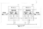
- the communication system includes a first electronic control unit (ECU) 11, a second ECU 12, and a communication bus 10 as a communication line that connects the first and second ECUs 11 and 12 so that they can communicate with each other. Has been. Thus, the first and second ECUs 11 and 12 can exchange (transmit and receive) various control information and the like via the communication bus 10. Since the communication system is configured as a CAN (controller area network), the CAN protocol is applied as a communication protocol.
- CAN controller area network
- the communication bus 10 includes a communication line such as a twist cable, and transmits a communication message as communication data as one unit in communication in the CAN protocol via the communication line.
- the communication bus 10 may include wireless communication as part of a communication path, or may include a path that passes through another network via a gateway or the like.
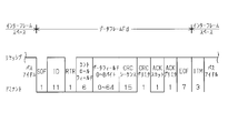
- frames that are structures of communication messages are structures of communication messages, and one of them is a data frame Fd that can store data designated by the user.
- a data frame Fd that can store data designated by the user.
- the structure of a communication message as communication data of the CAN protocol will be described using the data frame Fd as an example.
- the data frame Fd mainly stores an area (“ID” in FIG. 2) in which “message ID” indicating the content of the communication message is stored and data designated by the user.
- An area of “data field” is provided. This “data field” is set in any length of 0 to 64 bits (8 bits ⁇ 0 to 8 bytes).
- the data frame Fd includes an SOF (start of frame) area, an RTR (remote transmission request) area, a control field area, a CRC (CRC) area, an ACK (acknowledge) area, and an EOF area defined by the CAN protocol. Is secured.
- the ACK area is an area for confirming that the frame has been normally received.
- the ACK area includes a 1-bit ACK slot in which a response confirmation from the receiving side is transmitted, and a 1-bit ACK delimiter that is a delimiter of the ACK slot.
- the ACK delimiter is always “1” (recessive).
- the receiving side checks the content of the received data frame Fd with the check code stored in the CRC area, and sets “0” in the ACK slot if the check result is normal, and the ACK slot if there is an abnormality. An acknowledge is returned by setting "1" to. When there is no receiving side, “1” set by the transmitting side is maintained in the ACK slot.
- the transmitting side can confirm that the data frame Fd transmitted based on the monitored ACK slot being “0” has been normally received by the receiving side.
- the transmission side can confirm that the data frame Fd transmitted based on the monitored ACK slot being “1” is not normally received by the reception side. Therefore, the transmission side determines that an ACK error among communication errors has occurred based on detecting that the monitored ACK slot is “1”.
- Factors that cause no response from other ECUs include a vehicle state in which only one ECU is activated on the communication bus 10, and optional ECUs that are not necessarily connected to the communication bus 10. Are all not provided (optionless).
- a remote frame which is one of the CAN protocol communication message frames, also has an ACK area similar to the above, and therefore it is possible to determine the presence or absence of an ACK error.
- the ECU on the transmitting side transmits a data frame Fd when there is no receiving ECU that receives the data frame Fd, an ACK error is detected and detected.
- the error count increases due to a communication error.
- the state is “error active”, when the error count of communication errors exceeds 127, the state is “error passive”, and when the error count of communication errors reaches 256, “bus off”. It becomes a state.
- the “error active” state is a state where normal transmission / reception can be performed
- the “error passive” state is a state where transmission / reception can be continued under restricted conditions
- the “bus off” state is a state where the ECU is off the network.
- the counter value decreases and the state is restored to the “error active” state.
- the “bus off” state is entered, in order to return from the “bus off” state, for example, resetting or configuration of the ECU is required, so that the return is not easy. Therefore, in the first embodiment, when a communication error is detected as normal error processing, the error count of the communication error is cleared, and communication (transmission) is performed only once after a predetermined time (for example, 100 ms) has elapsed. ) To perform error handling that can be automatically restored. The predetermined time is set in advance based on experience, experiment, theory, etc. without increasing the communication load of the communication bus 10 and with little delay required for recovery.
- each of the first and second ECUs 11 and 12 is a control device used for various controls of the vehicle 1, for example, a drive system, a traveling system, a vehicle body system, an information equipment system, or the like.
- This is the ECU to be controlled.
- ECUs that control the drive system include engine ECUs, HV (hybrid) ECUs, and charge control ECUs
- ECUs that control the travel system include steering ECUs and brake ECUs.
- examples of ECUs that control the vehicle body system include door ECUs, seat ECUs, light ECUs, window ECUs, and air conditioner ECUs
- ECUs that control information equipment systems include audio ECUs and car navigation ECUs. Can be mentioned.
- Each of the first and second ECUs 11 and 12 is connected to a device to be monitored as an external device or a device to be controlled so as to be able to receive a signal via a wiring, a LIN (local interconnect network), or the like.
- the external device detects information related to the vehicle state using a sensor or the like, and outputs the detected vehicle state as external information.
- Each of the first and second ECUs 11 and 12 acquires a signal output from an external device as external information.
- External devices include devices that detect and control the opening and closing of doors, devices that detect and control the shape of sheets, and external information includes door opening and closing information and operation information, sheet shape information and operation information. Etc.
- Each of the first and second ECUs 11 and 12 includes an information processing device 111 that executes processing required for various controls and processes communication information, and a CAN controller 112 that transmits and receives communication messages based on the CAN protocol. .
- the information processing apparatus 111 and the CAN controller 112 are connected via an internal bus or the like, and various data can be exchanged between the information processing apparatus 111 and the CAN controller 112. Then, the first and second ECUs 11 and 12 perform error processing related to the communication of the CAN protocol described above through processing in the information processing apparatus 111, the CAN controller 112, and the like.
- the CAN controller 112 transmits and receives communication messages to and from the communication bus 10.
- the CAN controller 112 receives a communication message based on the CAN protocol and transmits a communication message based on the CAN protocol. That is, each of the first and second ECUs 11 and 12 transmits / receives a communication message to / from the communication bus 10 via the CAN controller 112. Therefore, the first and second ECUs 11 and 12 can mutually transmit and receive communication messages having a frame structure defined by the CAN protocol via each CAN controller 112.
- the CAN controller 112 can provide the information included in the communication message to the information processing apparatus 111. Further, the CAN controller 112 transmits a communication message based on the data contents provided from the information processing apparatus 111 and a transmission instruction.
- the CAN controller 112 monitors the communication message being transmitted, that is, monitors the communication message to detect that the communication message being transmitted collides with another communication message, and performs an arbitration or ACK response to prevent the communication message from colliding. Perform detection. Then, the CAN controller 112 provides the detected signal of the ACK area to the information processing apparatus 111. As a result, the information processing apparatus 111 determines whether or not there is an ACK error for the communication message being transmitted based on whether the signal of the ACK slot is “1” or “0” during transmission of the communication message. Detect.
- Each information processing device 111 of the first and second ECUs 11 and 12 includes a microcomputer having a calculation device (CPU) and a storage device.
- the information processing device 111 temporarily stores an arithmetic device that executes arithmetic processing of the control program, a read-only memory (ROM) that stores the control program and data, and the arithmetic result of the arithmetic device.
- Volatile memory (RAM) volatile memory
- the information processing apparatus 111 reads a control program stored in the storage device into the arithmetic device and executes it, thereby performing a predetermined function for the control target and controlling the control target.
- the information processing apparatus 111 includes a communication necessity determination unit 113 that determines whether it is necessary to exchange a communication message via the communication bus 10 and a communication control unit 114 that controls transmission / reception of the communication message. .
- the information processing apparatus 111 reads and executes a program for determining the necessity of transmission / reception of communication messages held in the storage device and a program for performing various processes for controlling transmission / reception of communication messages, respectively, on the arithmetic device. . Thereby, the information processing apparatus 111 is provided with the functions of the communication necessity determination unit 113 and the communication control unit 114 described above.
- the communication necessity determination unit 113 determines whether or not information communication such as transmission of a communication message via the communication bus 10 is necessary based on external information input (acquired) to the ECUs 11 and 12. Judgment (communication necessity judgment step). Examples of such external information include operation inputs and response inputs from external devices connected to the ECUs 11 and 12. The external information may include information on the key position of the vehicle and information indicating that charging is in progress. The communication necessity determination unit 113 determines that information communication is unnecessary, that is, “No”, when it is determined by external information that the process for the control target device (external device) can be performed by the ECU alone.
- control target device when it is determined from external information that the control target device (external device) needs to be linked with another device, it is determined that information communication is necessary, that is, “necessary”.
- processing for a control target device that is determined not to require information communication include opening / closing processing of a door of a parked vehicle, processing of operating a seat of a parked vehicle, processing of operating an audio of a parked vehicle, etc. Is mentioned.
- parking can be determined from the fact that the key position is “IG OFF”, the vehicle 1 is being charged, and the like.
- an example of a process for a control target device that is determined to require information communication includes a process of operating an air conditioner of a parked vehicle. By the way, these processes and the necessity of information communication may differ depending on the vehicle type and configuration.
- the communication control unit 114 can acquire the determination result as to whether or not information communication is necessary from the communication necessity determination unit 113, and can acquire the data of the ACK area detected by the CAN controller 112. Thus, it is possible to determine whether or not there is an ACK error. And the communication control part 114 controls the information communication performed via the CAN controller 112 based on the presence or absence of an ACK error and the judgment result whether information communication is required (communication control process).
- the communication control unit 114 when there is no ACK error, the communication control unit 114 does not restrict transmission of a communication message from the CAN controller 112 and performs normal CAN communication.
- the communication control unit 114 controls information communication with reference to a determination result as to whether or not information communication is necessary. In other words, when there is an ACK error and it is a determination result that information communication is necessary, transmission of a communication message from the CAN controller 112 is not restricted, normal CAN communication is maintained, and a normal error is maintained. Process. Note that in the first embodiment, as normal error processing, for example, transmission and reception of communication messages are stopped for a certain period (for example, 100 ms) on condition that a communication error is detected. Perform processing to resume communication. Therefore, every time it is determined that there is an ACK error and it is determined that information communication is necessary, this normal error processing is repeated.
- the transmission of the communication message from the CAN controller 112 is restricted, while the reception of the communication message by the CAN controller 112 is continue.
- the determination that there is an ACK error and that the determination result is that information communication is not necessary is maintained, transmission of communication messages and reception are continuously maintained.
- the process proceeds to a process of performing normal CAN communication.
- the communication message received by the CAN controller 112 includes a communication message transmitted from the ECU when another ECU is activated on the receiving side.
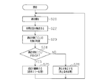
- the operation of the communication error processing of the first and second ECUs 11 and 12 will be described with reference to FIG.
- the communication error process of the first ECU 11 will be described, and the description of the communication error process of the second ECU 12 will be omitted. That is, a case where the transmission side is the first ECU 11 and the reception side is the second ECU 12 will be described.
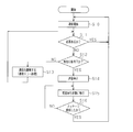
- the first ECU 11 starts operation by being turned on or activated from the sleep state, and starts normal CAN communication (step S10).
- the sleep state of the ECU is a state in which the ECU is in a power saving mode in order to suppress power consumption when the ECU is supplied with power but does not need to be activated.
- the vehicle state in which the ECU is in the sleep state the battery is being charged if it is not the charge control ECU.
- the ECU is activated from the sleep state on condition that the device to be controlled is operated during the power saving mode. Examples of operations for starting the ECU from the sleep state include air-conditioner operations, audio operations, door opening / closing, and seat position changes.
- the ECU is operated by the user during charging of the vehicle such as “turn on the air conditioner because it is hot”, “watch the in-vehicle TV because it is free”, “open the door to get on”, “change the seat position”, etc. Wake up from sleep.
- the first ECU 11 determines whether or not there is a response to the transmitted communication message (step S11). Whether or not there is a response is determined by the presence or absence of an ACK error. If there is no ACK error, there is a response, and if there is an ACK error, it is determined that there is no response. In the first embodiment, there is a response when the second ECU 12 is activated, and there is no response when the second ECU 12 is not activated. If it is determined that there is a response (YES in step S11), the first ECU 11 returns the process to step S10 and starts normal CAN communication by the next communication message, that is, normal CAN communication is continued. .
- the first ECU 11 determines whether or not the vehicle state is under a specific condition (step S12).
- the specific condition of the vehicle state is a condition that is determined depending on whether or not information communication is necessary. More specifically, when it is determined that information communication is necessary ("necessary"), it is determined that it is not under a specific condition, and when it is not necessary (“no") Is determined to be under certain conditions.
- step S13 If it is determined that the specific condition is not satisfied (NO in step S12), the first ECU 11 continues communication based on normal communication error processing (step S13).
- normal communication error processing as a return determination, transmission of a communication message is repeated at regular intervals (for example, 100 ms) to confirm the presence or absence of an ACK error. Therefore, in the case of normal error processing, the first ECU 11 consumes power each time a communication message is transmitted.
- step S12 if it is determined that the specific condition is satisfied (YES in step S12), the first ECU 11 stops transmission of the communication message (step S14) and waits for reception to continue reception of the communication message. The state is shifted (step S15). Under specific conditions, information communication is not necessary in the first place, and communication does not return. Therefore, the return determination as shown in step S13 is not executed. Therefore, since the communication message is not transmitted in the reception waiting state, the power consumption of the first ECU 11 is suppressed. For example, even if the interval is long, the amount of power consumed cannot be ignored if transmission of a communication message at regular intervals is performed over a long period of time.
- the first ECU 11 determines whether or not a communication message is received at a predetermined interval or timing in the reception waiting state (step S16). That is, in the first embodiment, the transmission resumption condition is that a communication message is received. If it is determined that a communication message has not been received (NO in step S16), the first ECU 11 returns the process to step S15 and again enters a reception waiting state. On the other hand, if it is determined that a communication message has been received (YES in step S16), the first ECU 11 returns the process to step S10 and starts normal CAN communication using the next communication message.
- the first ECU 11 is prepared so that it can receive communication messages from other ECUs in a reception waiting state, and can appropriately respond to communication messages from other ECUs. ing.
- the operation of the above-described communication error processing is started when the first ECU 11 is started, and is ended when the first ECU 11 is stopped or reset.
- the presence / absence of an ECU that requires information communication and the activation state of another ECU are determined as needed, and transmission from the ECU is stopped. Will come to be.
- a communication device capable of suppressing power consumed for communication, a communication method used for the communication device, and a communication system including the communication device are provided. Can be provided.
- the communication system has the effects listed below.
- information communication is not required, information communication is not required and there is no need for return determination, so transmission of the communication message is stopped until a predetermined transmission resumption condition is satisfied. Thereby, in communication based on the CAN protocol, unnecessary communication is suppressed, and consequently, power consumed for communication by the communication device is suppressed.
- the charging time can be shortened by suppressing the power consumed during charging of the storage battery.
- the necessity of information communication via the communication bus 10 is determined according to the type of external information, the accuracy of such determination can be improved.
- a second embodiment embodying a communication system including a communication device will be described with reference to FIGS.
- the configuration of the communication system is a configuration including three communication buses that are communicably connected by a GW (gateway)
- the configuration of the communication system is different from the configuration of the first embodiment.
- the communication bus is used for information communication by the CAN protocol. Therefore, in the following, description of information communication using the CAN protocol described in detail in the first embodiment is omitted.
- the vehicle 2 is a plug-in hybrid vehicle or an electric vehicle that includes a communication system and a storage battery that can be charged from an external power source.
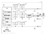
- the communication system provided in the vehicle 2 includes a GW (gateway) 50, a first bus 20, a second bus 30, and a first bus as communication lines connected to the GW 50, respectively. 3 buses 40.
- the first to third buses 20, 30, and 40 are configured as buses capable of transmitting CAN protocol communication messages, and include, for example, twisted pair cables.
- the GW 50 can relay (transfer) CAN protocol communication messages input from the first to third buses 20, 30, and 40 to other connected buses.
- the communication system has a configuration in which the first to third buses 20, 30, and 40 are interconnected via the GW 50, that is, a so-called star network configuration, and the first to third buses 20,
- the system is configured as a system capable of relaying (transferring) CAN protocol communication messages between 30 and 40.
- a plurality of ECUs are connected to the first to third buses 20, 30 and 40 so that they can communicate with other ECUs via the buses.
- an air conditioner ECU 21 and an audio ECU 22 are connected to the first bus 20 as communication devices, respectively.
- the second bus 30 is connected to a door ECU 31, a seat ECU 32, and a charge control ECU 33 as communication devices.
- the third bus 40 is connected to an HVECU 41 and an engine ECU 42 as communication devices.
- these ECUs have the same configuration as the information processing apparatus 111 and the CAN controller 112 described in the first embodiment.
- the air conditioner ECU 21 is an ECU for controlling an in-vehicle air conditioner as a control target device (external device), and acquires external information from the connected in-vehicle air conditioner.
- the audio ECU 22 is an ECU for controlling in-vehicle audio as a device to be controlled (external device), and acquires external information from the connected in-vehicle audio.
- the door ECU 31 is an ECU for controlling each door device for the vehicle door 61 as a device to be controlled (external device), and acquires external information from the door device connected via wiring, LIN, or the like.
- the seat ECU 32 is an ECU for controlling each seat device for the vehicle seat 62 as a device to be controlled (external device), and obtains external information from each seat device connected via wiring, LIN, or the like.
- the charge control ECU 33 is an ECU for controlling power output from the battery device 63 as a control target device (external device), charging of power from the external power source 70 to the battery device 63, and the like, and is connected by wiring or the like. It is possible to control charging / discharging of the battery device 63 to be performed. Note that the charging control ECU 33 can transmit information indicating that charging is being performed to each part of the vehicle 2 as needed using an appropriate communication path.
- the HV (hybrid) ECU 41 is an ECU that performs planning and adjustment of power distribution between driving by a battery and driving by an engine.
- the HVECU 41 acquires various types of information through CAN communication, and performs planning and adjustment of driving by the battery and driving by the engine based on the various types of information thus acquired.
- the engine ECU 42 is an ECU that controls driving of an engine that is an internal combustion engine.
- the engine ECU 42 controls driving of the engine based on various types of information obtained from various types of engine-related devices and other various types of devices as control target devices (external devices) connected by wiring or CAN.
- the GW 50 is a device having a configuration for outputting a communication message input from one bus to another bus, that is, a device that relays communication messages between a plurality of buses. Accordingly, communication messages are transmitted and received between the plurality of buses 20 to 40 via the GW 50 to which the buses 20 to 40 are connected.
- the GW 50 is a so-called ECU, and includes a microcomputer having a calculation unit and a storage unit. Therefore, the GW 50 provides a predetermined function such as a communication message relay function by reading the control program and various parameters held in the storage unit 54 into the arithmetic unit and executing them.
- the GW 50 receives a vehicle status from an external device via wiring, LIN, or the like, and also receives a CAN protocol communication message as a vehicle status from the external device.
- the ECUs 21 to 42 and the storage unit 54 of the GW 50 store setting information used for determining whether communication is necessary.
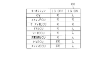
- the list 80 in FIG. 5 shows an example of the relationship between the GW 50 and each of the ECUs 21 to 42 that can be activated or not, or the power-on and the key position.
- the storage unit 54 and the like indicate that the GW 50, the air conditioner ECU 21, the audio ECU 22, the door ECU 31, the seat ECU 32, and the charge control ECU 33 can be activated when the key position is “IG OFF”, the HVECU 41, The engine ECU 42 is set to be unable to start.
- the key position is “IG OFF”, the key position is “OFF” and the key position is “ACC”. Further, when the key position is “IG ON”, the GW 50, the door ECU 31, the seat ECU 32, the charge control ECU 33, the HVECU 41, and the engine ECU 42 are turned on and activated, and the air conditioner ECU 21 and the audio ECU 22 can be activated. Is set. Note that the setting information stored in each of the ECUs 21 to 42 may be only information related to the bus to which the ECU is connected.
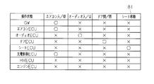
- the list 81 in FIG. 6 shows an example of the relationship between the vehicle state grasped from the external information and the GW 50 that needs to be activated in accordance with the vehicle state and each of the ECUs 21 to 42.
- the storage unit 54 and the like have operations of “air conditioner on / off”, “audio on / off”, “door open / close”, and “seat movement” as vehicle states.
- the relationship between the necessity of transferring the communication message of the GW 50 and the necessity of starting each of the ECUs 21 to 42 is set. In FIG. 6, “ ⁇ ” indicates that transfer or activation is required, and “X” indicates that transfer or activation is not required.
- the GW 50 needs to be transferred, and the air conditioner ECU 21 and the charge control ECU 33 need to be activated, while other ECUs need not be activated. Is set.
- the “audio on / off” operation it is set that the audio ECU 22 needs to be activated, while the other ECUs are unnecessary to be activated, and the transfer of the GW 50 is also unnecessary.
- the “door open / close” operation it is set that the door ECU 31 needs to be activated, while the other ECUs are unnecessary to be activated and the GW 50 is not required to be transferred.
- the “seat movement” operation When the “seat movement” operation is performed, it is set that the seat ECU 32 needs to be activated, while the other ECUs are not activated, and the transfer of the GW 50 is also unnecessary.
- the setting information stored in each of the ECUs 21 to 42 may be only information related to the bus to which the ECU is connected.
- the GW 50 is connected to the first to third buses 20 to 40, receives a communication message from the buses 20 to 40, and receives a communication message to the buses 20 to 40. It has.
- the GW 50 includes a communication necessity determination unit 52 that determines whether the received communication message needs to be relayed, a communication control unit 53 that controls transmission of a communication message according to a determination result by the communication necessity determination unit 52, And a storage unit 54 in which setting information used for determination by the rejection determination unit 52 is stored.
- the message receiving unit 51 receives a CAN protocol communication message, and makes the data included in the communication message available in the communication necessity determination unit 52 of the GW 50 or the like.
- the communication control unit 53 controls the transfer of the communication message to the buses 20 to 40 to be transmitted.
- the GW 50 transfers the communication message received from the first bus 20 to the second and third buses 30 and 40, or the communication message received from the second bus 30 to the first and third buses.
- the communication message received from the third bus 40 is transferred to the buses 20 and 40, and the communication message received from the third bus 40 is transferred to the first and second buses 20 and 30. There may be a bus that is not transferred.
- the communication necessity determination unit 52 has the same function as the communication necessity determination unit 113 of the first embodiment.
- the communication necessity determination unit 52 is used for determining external information such as information input (acquired) from an external device or information of an ECU performing communication, and necessity of communication set in the storage unit 54. Based on the set information, it is determined whether information communication by transfer of a communication message is necessary.
- the communication necessity determination unit 52 determines that information communication is unnecessary when it is determined by external information that the communicating ECU can perform processing on the device to be controlled alone, while in other cases, For example, when it is determined that another device is required to control the control target device, it is determined that information communication is necessary. Further, the communication necessity determination unit 52 acquires the key position information of the vehicle 2, and based on the key position information and the setting information used for determining the necessity of communication set in the storage unit 54. Thus, it is determined whether information communication by transfer of a communication message is necessary.
- the communication necessity determination unit 52 activates the audio shown in the list 81, opens / closes the door 61, and activates the seat 62. It is determined that information communication is unnecessary because the ECU can process each ECU independently. On the other hand, for example, when the key position is “IG OFF”, in the process of operating the air conditioner, it is determined that information communication is necessary because processes in a plurality of ECUs with different buses are required.
- the vehicle corresponding to the key position shown in the list 80 is “IG ON” while the vehicle is stopped or running, the audio shown in the list 81 is activated, the door 61 is opened and closed, and the seat 62 is activated.
- the ECU can process it alone, as shown in the list 80, it is determined that information communication is necessary because the GW 50 or the like is powered on and operating.
- the key position is “IG ON”, it is determined that information communication is necessary because the processing for operating the air conditioner requires processing by a plurality of ECUs with different connected buses.
- the communication control unit 53 has the same function as the communication control unit 114 of the first embodiment.
- the communication control unit 53 can acquire a determination result as to whether or not information communication is necessary from the communication necessity determination unit 52 and also acquire data in the ACK area detected by the message reception unit 51. Thus, it is possible to determine whether or not there is an ACK error.
- the communication control part 53 controls the information communication performed via the message transmission part 55 based on the presence or absence of an ACK error and the judgment result whether information communication is required.
- the audio ECU 22 starts its operation when the power is turned on or is activated from the sleep state, and starts normal CAN communication (step S20).
- normal CAN communication is started, the audio ECU 22 determines whether or not there is a response to the transmitted communication message, and specifies the vehicle state based on external information or the like (step S22).
- step S22 a case where there is no response to a communication message and a communication error is detected will be described.
- the audio ECU 22 determines whether or not there is a communication target ECU (step S23).
- the determination as to whether or not there is a communication target ECU is based on the relationship between the current key position and the activated ECU (see list 80), or the relationship with the ECU required for processing the “audio on / off” operation (list). 81). It is also determined that there is a communication target ECU when there is a response to the transmitted communication message. If it is determined that there is a communication target ECU (YES in step S24), the audio ECU 22 continues normal error processing (step S25). That is, the audio ECU 22 returns the process to step S20 with a certain interval, and continues normal CAN communication.
- step S24 when it is determined that there is no communication target ECU (NO in step S24), the audio ECU 22 stops transmission of the communication message and shifts to a reception waiting state for continuing reception of the communication message (step S26). ). Then, based on the determination that the communication message has been received, the audio ECU 22 returns the process to step S20 and starts normal CAN communication.
- the GW 50 starts operation when the power is turned on or is activated from the sleep state, and starts normal CAN communication that enables transfer of a communication message (step S20).
- the GW 50 can determine the presence or absence of an ECU that responds in each of the buses 20 to 40 in this normal CAN communication. That is, the GW 50 determines whether or not the ECUs on the buses 20 to 40 communicate with ECUs on other buses.
- the GW 50 determines the presence / absence of a communication error and specifies the vehicle state based on external information or the like (step S22).
- a communication error is detected will be described.
- the GW 50 determines whether or not the communication target ECU exists on a bus different from the communication source bus based on the specified vehicle state (step S23). If it is determined that there is a communication target ECU on another bus (YES in step S24), the GW 50 continues communication between the buses based on normal communication error processing (step S25). That is, the GW 50 returns the process to step S20 and continues normal CAN communication that enables transfer of a communication message between the buses.
- step S24 when it is determined that there is no communication target ECU on another bus (NO in step S24), the GW 50 stops transmission of the communication message from the communication source bus to the communication destination bus, and The process shifts to a reception waiting state for continuing reception (step S26).
- the GW 50 returns the process to step S20 and starts normal CAN communication that enables transfer of the communication message.
- a communication device capable of suppressing power consumed for communication, a communication method used for the communication device, and a communication system including the communication device are provided. Can be provided.
- the communication system according to the second embodiment has the effects listed below in addition to the effects (1) to (5) described in the first embodiment. (6) Since information communication is suppressed when the device operated by the user does not require information communication, power consumption can be reduced.
- the door opening / closing operation and the seat position operation may be performed while the vehicle 2 is parked. However, if the vehicle 2 is parked in this way, only the communication device necessary for these operations may be activated. In addition, information communication via a communication line may not be necessary for these operations. Therefore, power consumption of the communication device can be reduced by not performing information communication only when opening and closing the door or operating the seat position.
- a third embodiment embodying the communication system will be described with reference to FIG.
- the communication history is different from that of the first embodiment in determining whether or not there is a communication target ECU, but the other configurations are the same. Therefore, in the following, the configuration that is different from the first embodiment will be mainly described, and the detailed description of the same configuration is omitted.
- the first ECU 11 holds various vehicle states and ECUs that have communicated in the vehicle state as history.
- the latest information is held for each vehicle state.
- two or more pieces of latest information may be stored as a history.
- contents of the history contents that are not updated for a predetermined period or more or a certain number of activations may be deleted.
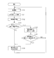
- the operation of the communication error processing shown in FIG. 8 will be described by taking the first ECU 11 as an example in the third embodiment.
- the first ECU 11 starts operation by being turned on or activated from the sleep state, and starts normal CAN communication (step S30).
- the first ECU 11 detects that there is no response to the transmitted communication message (step S31).
- normal CAN communication is performed although not shown.
- the first ECU 11 checks the communication history (step S32). In the confirmation of the communication history, the vehicle state is specified based on external information, and the presence / absence of an ECU that has communicated in the past in the vehicle state is acquired. And 1st ECU11 judges the presence or absence of ECU which communicated in the past in the said vehicle state (step S33).
- the first ECU 11 When it is determined that there is an ECU that has communicated in the past in the vehicle state (YES in step S33), the first ECU 11 continues communication based on normal communication error processing (step S34) and performs such normal communication. It is determined whether the error process has been repeated a predetermined number of times or more (step S35). If it is determined that the communication error process has not been repeated more than the predetermined number of confirmations (NO in step S35), the first ECU 11 returns the process to step S30, and continues normal CAN communication while performing normal error processing. To do. That is, each time a communication message is transmitted in normal error processing, the first ECU 11 consumes power.
- step S36 when it is determined that no ECU has communicated in the past in the vehicle state (NO in step S33), or when it is determined that the communication error process has been repeated a predetermined number of times (YES in step S35), 1 ECU11 stops transmission of a communication message (step S36).
- the first ECU 11 shifts to a reception waiting state for continuing reception of the communication message, so that power consumption is suppressed.
- the reception waiting state in response to the reception of the communication message, the first ECU 11 returns the process to step S30 and starts normal CAN communication using the next communication message.
- the operation of the communication error process starts when the first ECU 11 is activated, and is terminated when the first ECU 11 is stopped or reset.
- the communication system according to the third embodiment has the effects listed below in addition to the effects (1) to (5) described in the first embodiment.
- Information communication and external information are associated with each other and stored as a history. Then, based on referring to the stored history, it is determined whether there is an ECU serving as a communication partner according to the external information to be acquired.
- the history for example, after shipment of the vehicle manufacturing factory, the type or number of ECUs connected to the communication bus may be changed, or the function may be changed to change the communication partner ECU. If you do, you can respond to such changes. As a result, the presence or absence of a communication partner corresponding to the acquired external information can be suitably determined.
- each said embodiment can also be implemented with the following aspects.
- the case where the data frame has a standard format has been illustrated.
- the present invention is not limited to this, and the data frame may be an extended format. Thereby, the improvement of the design freedom of a communication system comes to be aimed at.
- the present invention is not limited to this, and the number of communication buses may be 2 or 4 or more. As a result, the applicability of such a communication system can be expanded.
- the present invention is not limited to this, and the number of ECUs or the like connected to the bus may be any number that conforms to the CAN protocol standard, and may be four or more. Thereby, the freedom degree of the structure of a communication system is improved.
- the ECUs 11, 12, 21 to 42 are illustrated as having a configuration including the communication necessity determination unit 113 and the communication control unit 114, but the communication necessity determination unit and the communication control unit As long as it has a configuration having a function to be exhibited, this configuration may be divided in any way.
- the GW 50 is configured to include the message reception unit 51, the communication necessity determination unit 52, the communication control unit 53, the storage unit 54, and the message transmission unit 55 is illustrated.
- the present invention is not limited to this, and if the GW is provided with a configuration having functions exhibited by the message reception unit, the communication necessity determination unit, the communication control unit, the storage unit, and the message transmission unit, how this configuration is classified. May be.
- the communication resumption condition is to receive a communication message.
- the present invention is not limited to this, and as a communication resumption condition, the communication necessity determination unit that determines that the necessity of information communication is “No” determines that information communication is necessary due to subsequent changes in the state of the vehicle, etc.
- the transmission resumption condition may be satisfied based on the determination. That is, even if the communication apparatus suppresses the power required for communication due to the determination that information communication is not necessary, the communication is appropriately restored as necessary.
- the present invention is not limited to this, and if it is possible to specify that there is no communication partner, there is no signal generated based on the ACK error message indicating that “transmission is not completed” or a response generated based on other errors. It may be determined that there is no communication partner based on a signal or the like. As a result, the degree of freedom in designing the communication device can be improved.
- each ECU the case where a communication necessity determination unit is provided in each ECU is illustrated.
- the present invention is not limited to this, and the communication necessity determination unit may be provided in some ECUs. This also makes it possible to reduce the power consumption of the ECU having the communication determination unit.
- the present invention is not limited to this, and such settings may be set only for the required ECU or only for the GW. Then, only the required ECU or GW may determine whether or not information communication is necessary by referring to such settings. Thereby, the design freedom of the communication system can be improved.
- the present invention is not limited to this, and if the determination of the necessity of information communication and the determination of the presence or absence of an ACK error are performed as necessary, the presence or absence of an ACK error may be determined after determining the vehicle state. These determinations may be made in parallel. As a result, the degree of freedom in designing the communication device can be improved.
- the present invention is not limited to this, and if the determination of the necessity of information communication and the determination of the presence or absence of an ACK error are performed as necessary, the presence or absence of an ACK error may be determined after confirming the communication history. These determinations may be made in parallel. As a result, the degree of freedom in designing the communication device can be improved.
- the communication bus is a bus based on the CAN protocol.
- the present invention is not limited to this, and the communication protocol is a protocol other than the CAN protocol as long as it is a communication bus to which a plurality of communication devices are connected and the communication device can determine the presence or absence of the receiving side. Also good. Thereby, the applicability of the communication system can be expanded.
- the vehicles 1 and 2 are plug-in hybrid vehicles and electric vehicles are exemplified.
- the vehicle may be a hybrid vehicle or a vehicle using only an engine as a drive source.
- this communication system may be provided in a mobile body other than an automobile vehicle, for example, a ship, a railway, an industrial machine, a robot, or the like.
Abstract
Priority Applications (4)
| Application Number | Priority Date | Filing Date | Title |
|---|---|---|---|
| CN201580012543.8A CN106464552B (zh) | 2014-03-10 | 2015-02-27 | 通信装置、通信方法以及通信系统 |
| US15/124,214 US10243760B2 (en) | 2014-03-10 | 2015-02-27 | Communication device, communication method, and communication system |
| KR1020167027034A KR101851092B1 (ko) | 2014-03-10 | 2015-02-27 | 통신 장치, 통신 방법 및 통신 시스템 |
| EP15760750.8A EP3119038B1 (fr) | 2014-03-10 | 2015-02-27 | Dispositif de communication, procédé de communication et système de communication |
Applications Claiming Priority (2)
| Application Number | Priority Date | Filing Date | Title |
|---|---|---|---|
| JP2014-046290 | 2014-03-10 | ||
| JP2014046290A JP5958975B2 (ja) | 2014-03-10 | 2014-03-10 | 通信装置、通信方法及び通信システム |
Publications (1)
| Publication Number | Publication Date |
|---|---|
| WO2015137164A1 true WO2015137164A1 (fr) | 2015-09-17 |
Family
ID=54071612
Family Applications (1)
| Application Number | Title | Priority Date | Filing Date |
|---|---|---|---|
| PCT/JP2015/055868 WO2015137164A1 (fr) | 2014-03-10 | 2015-02-27 | Dispositif de communication, procédé de communication, et système de communication |
Country Status (6)
| Country | Link |
|---|---|
| US (1) | US10243760B2 (fr) |
| EP (1) | EP3119038B1 (fr) |
| JP (1) | JP5958975B2 (fr) |
| KR (1) | KR101851092B1 (fr) |
| CN (1) | CN106464552B (fr) |
| WO (1) | WO2015137164A1 (fr) |
Cited By (1)
| Publication number | Priority date | Publication date | Assignee | Title |
|---|---|---|---|---|
| US9927376B2 (en) | 2016-03-15 | 2018-03-27 | Toshiba Memory Corporation | Template defect inspection method |
Families Citing this family (60)
| Publication number | Priority date | Publication date | Assignee | Title |
|---|---|---|---|---|
| US10599840B2 (en) * | 2016-07-21 | 2020-03-24 | Ramot At Tel Aviv University Ltd. | Anti-spoofing defense system for a can bus |
| JP6485437B2 (ja) * | 2016-12-12 | 2019-03-20 | トヨタ自動車株式会社 | 車載通信システム |
| JP6515911B2 (ja) * | 2016-12-16 | 2019-05-22 | トヨタ自動車株式会社 | 車載ネットワークシステム |
| US10369988B2 (en) | 2017-01-13 | 2019-08-06 | Ford Global Technologies, Llc | Autonomous parking of vehicles inperpendicular parking spots |
| MX2019008708A (es) | 2017-01-25 | 2019-12-11 | SEA Automotive Pty Ltd | Sistema de gestion para vehiculos electricos comerciales. |
| JP6406559B2 (ja) | 2017-03-17 | 2018-10-17 | 本田技研工業株式会社 | 通信装置、通信方法、およびプログラム |
| US10683034B2 (en) | 2017-06-06 | 2020-06-16 | Ford Global Technologies, Llc | Vehicle remote parking systems and methods |
| US10775781B2 (en) | 2017-06-16 | 2020-09-15 | Ford Global Technologies, Llc | Interface verification for vehicle remote park-assist |
| US10234868B2 (en) | 2017-06-16 | 2019-03-19 | Ford Global Technologies, Llc | Mobile device initiation of vehicle remote-parking |
| US10585430B2 (en) | 2017-06-16 | 2020-03-10 | Ford Global Technologies, Llc | Remote park-assist authentication for vehicles |
| US10580304B2 (en) | 2017-10-02 | 2020-03-03 | Ford Global Technologies, Llc | Accelerometer-based external sound monitoring for voice controlled autonomous parking |
| US10281921B2 (en) | 2017-10-02 | 2019-05-07 | Ford Global Technologies, Llc | Autonomous parking of vehicles in perpendicular parking spots |
| US10627811B2 (en) | 2017-11-07 | 2020-04-21 | Ford Global Technologies, Llc | Audio alerts for remote park-assist tethering |
| US10336320B2 (en) | 2017-11-22 | 2019-07-02 | Ford Global Technologies, Llc | Monitoring of communication for vehicle remote park-assist |
| US10578676B2 (en) | 2017-11-28 | 2020-03-03 | Ford Global Technologies, Llc | Vehicle monitoring of mobile device state-of-charge |
| US10688918B2 (en) | 2018-01-02 | 2020-06-23 | Ford Global Technologies, Llc | Mobile device tethering for a remote parking assist system of a vehicle |
| US10974717B2 (en) | 2018-01-02 | 2021-04-13 | Ford Global Technologies, I.LC | Mobile device tethering for a remote parking assist system of a vehicle |
| US11148661B2 (en) | 2018-01-02 | 2021-10-19 | Ford Global Technologies, Llc | Mobile device tethering for a remote parking assist system of a vehicle |
| US10737690B2 (en) | 2018-01-02 | 2020-08-11 | Ford Global Technologies, Llc | Mobile device tethering for a remote parking assist system of a vehicle |
| US10583830B2 (en) | 2018-01-02 | 2020-03-10 | Ford Global Technologies, Llc | Mobile device tethering for a remote parking assist system of a vehicle |
| US10814864B2 (en) | 2018-01-02 | 2020-10-27 | Ford Global Technologies, Llc | Mobile device tethering for a remote parking assist system of a vehicle |
| US10585431B2 (en) | 2018-01-02 | 2020-03-10 | Ford Global Technologies, Llc | Mobile device tethering for a remote parking assist system of a vehicle |
| US10684773B2 (en) | 2018-01-03 | 2020-06-16 | Ford Global Technologies, Llc | Mobile device interface for trailer backup-assist |
| US10747218B2 (en) | 2018-01-12 | 2020-08-18 | Ford Global Technologies, Llc | Mobile device tethering for remote parking assist |
| US10917748B2 (en) | 2018-01-25 | 2021-02-09 | Ford Global Technologies, Llc | Mobile device tethering for vehicle systems based on variable time-of-flight and dead reckoning |
| JP6878324B2 (ja) * | 2018-01-31 | 2021-05-26 | 日立Astemo株式会社 | 車載ネットワークシステム、電子制御装置 |
| US10684627B2 (en) | 2018-02-06 | 2020-06-16 | Ford Global Technologies, Llc | Accelerometer-based external sound monitoring for position aware autonomous parking |
| US11188070B2 (en) | 2018-02-19 | 2021-11-30 | Ford Global Technologies, Llc | Mitigating key fob unavailability for remote parking assist systems |
| US10507868B2 (en) | 2018-02-22 | 2019-12-17 | Ford Global Technologies, Llc | Tire pressure monitoring for vehicle park-assist |
| US10732622B2 (en) | 2018-04-05 | 2020-08-04 | Ford Global Technologies, Llc | Advanced user interaction features for remote park assist |
| US10493981B2 (en) | 2018-04-09 | 2019-12-03 | Ford Global Technologies, Llc | Input signal management for vehicle park-assist |
| US10683004B2 (en) | 2018-04-09 | 2020-06-16 | Ford Global Technologies, Llc | Input signal management for vehicle park-assist |
| US10759417B2 (en) | 2018-04-09 | 2020-09-01 | Ford Global Technologies, Llc | Input signal management for vehicle park-assist |
| US10793144B2 (en) | 2018-04-09 | 2020-10-06 | Ford Global Technologies, Llc | Vehicle remote park-assist communication counters |
| US10232673B1 (en) | 2018-06-01 | 2019-03-19 | Ford Global Technologies, Llc | Tire pressure monitoring with vehicle park-assist |
| JP7018827B2 (ja) * | 2018-06-13 | 2022-02-14 | 本田技研工業株式会社 | 通信システム及び車両 |
| US10384605B1 (en) | 2018-09-04 | 2019-08-20 | Ford Global Technologies, Llc | Methods and apparatus to facilitate pedestrian detection during remote-controlled maneuvers |
| KR102646674B1 (ko) * | 2018-09-04 | 2024-03-13 | 현대자동차주식회사 | 차량 및 그 제어 방법 |
| US10717432B2 (en) | 2018-09-13 | 2020-07-21 | Ford Global Technologies, Llc | Park-assist based on vehicle door open positions |
| US10821972B2 (en) | 2018-09-13 | 2020-11-03 | Ford Global Technologies, Llc | Vehicle remote parking assist systems and methods |
| WO2020059015A1 (fr) * | 2018-09-18 | 2020-03-26 | 三菱電機株式会社 | Dispositif et procédé de commande de surveillance |
| US10529233B1 (en) | 2018-09-24 | 2020-01-07 | Ford Global Technologies Llc | Vehicle and method for detecting a parking space via a drone |
| US10967851B2 (en) | 2018-09-24 | 2021-04-06 | Ford Global Technologies, Llc | Vehicle system and method for setting variable virtual boundary |
| US10908603B2 (en) | 2018-10-08 | 2021-02-02 | Ford Global Technologies, Llc | Methods and apparatus to facilitate remote-controlled maneuvers |
| US10628687B1 (en) | 2018-10-12 | 2020-04-21 | Ford Global Technologies, Llc | Parking spot identification for vehicle park-assist |
| US11396246B2 (en) * | 2018-10-15 | 2022-07-26 | Ford Global Technologies, Llc | Energy-consumption detection of vehicles in an off state |
| US11097723B2 (en) | 2018-10-17 | 2021-08-24 | Ford Global Technologies, Llc | User interfaces for vehicle remote park assist |
| US11137754B2 (en) | 2018-10-24 | 2021-10-05 | Ford Global Technologies, Llc | Intermittent delay mitigation for remote vehicle operation |
| US11789442B2 (en) | 2019-02-07 | 2023-10-17 | Ford Global Technologies, Llc | Anomalous input detection |
| US11195344B2 (en) | 2019-03-15 | 2021-12-07 | Ford Global Technologies, Llc | High phone BLE or CPU burden detection and notification |
| US11275368B2 (en) | 2019-04-01 | 2022-03-15 | Ford Global Technologies, Llc | Key fobs for vehicle remote park-assist |
| JP7201073B2 (ja) * | 2019-04-01 | 2023-01-10 | 株式会社デンソー | 情報処理装置 |
| US11169517B2 (en) | 2019-04-01 | 2021-11-09 | Ford Global Technologies, Llc | Initiation of vehicle remote park-assist with key fob |
| US20220239406A1 (en) * | 2019-07-19 | 2022-07-28 | Hitachi Astemo, Ltd. | Gateway device, data frame transmission method, and program |
| CN111042970B (zh) * | 2019-12-11 | 2021-11-30 | 浙江锋锐发动机有限公司 | 一种车辆冷起动控制方法及其装置 |
| EP3838685A1 (fr) * | 2019-12-16 | 2021-06-23 | DEUTZ Aktiengesellschaft | Système de protocole de communication can destiné à l'échange des consommations de carburant et/ou des messages de consommation de fluide de fonctionnement et à faible niveau sonore entre les composants d'entrée et de sortie contribuant également à augmenter la disponibilité globale du système et procédé |
| DE102020006328A1 (de) | 2019-12-16 | 2021-06-17 | Deutz Aktiengesellschaft | CAN-Kommunikationsprotokollsystem zum Austausch von Kraftstoffverbrauch und/oder betriebsflüssigkeitsverbrauchs- und geräuschoptimierenden Botschaften zwischen An- und Abtriebskomponenten, welche gleichfalls dazu beitragen, die Gesamtverfügbarkeit des Systems zu erhöhen und Verfahren |
| JP7336074B2 (ja) | 2020-03-04 | 2023-08-31 | スズキ株式会社 | 中継器 |
| JP7314858B2 (ja) * | 2020-04-30 | 2023-07-26 | トヨタ自動車株式会社 | 車両用制御システム |
| CN113472620A (zh) * | 2021-06-23 | 2021-10-01 | 重庆长安汽车股份有限公司 | 一种车内消息认证新鲜值的管理方法及系统 |
Citations (2)
| Publication number | Priority date | Publication date | Assignee | Title |
|---|---|---|---|---|
| JP2001339412A (ja) * | 2000-05-26 | 2001-12-07 | Mitsubishi Motors Corp | 車両用ネットワークの通信復帰判定方法 |
| JP2012204934A (ja) * | 2011-03-24 | 2012-10-22 | Fujitsu Ten Ltd | 通信装置および通信システム |
Family Cites Families (7)
| Publication number | Priority date | Publication date | Assignee | Title |
|---|---|---|---|---|
| JP3709769B2 (ja) * | 2000-07-27 | 2005-10-26 | 株式会社デンソー | 異常検出システム |
| JP4368902B2 (ja) * | 2007-04-20 | 2009-11-18 | 富士通テン株式会社 | エコラン制御装置及び制御方法 |
| JP4407752B2 (ja) * | 2008-01-10 | 2010-02-03 | トヨタ自動車株式会社 | 故障箇所検出装置及び通信装置並びに故障箇所検出方法 |
| WO2010052892A1 (fr) * | 2008-11-04 | 2010-05-14 | 株式会社オートネットワーク技術研究所 | Dispositif de communication, dispositif de relais, système de communication et procédé de communication |
| JP5717240B2 (ja) | 2010-08-09 | 2015-05-13 | 国立大学法人名古屋大学 | 通信システム及び通信装置 |
| US20120051241A1 (en) * | 2010-08-31 | 2012-03-01 | Denso Corporation | Communication system with a plurality of nodes communicably connected for communication based on NRZ (non return to zero) code |
| US8934351B2 (en) * | 2011-03-24 | 2015-01-13 | Fujitsu Ten Limited | Communication apparatus and communication system |
-
2014
- 2014-03-10 JP JP2014046290A patent/JP5958975B2/ja active Active
-
2015
- 2015-02-27 US US15/124,214 patent/US10243760B2/en active Active
- 2015-02-27 WO PCT/JP2015/055868 patent/WO2015137164A1/fr active Application Filing
- 2015-02-27 CN CN201580012543.8A patent/CN106464552B/zh active Active
- 2015-02-27 KR KR1020167027034A patent/KR101851092B1/ko active IP Right Grant
- 2015-02-27 EP EP15760750.8A patent/EP3119038B1/fr active Active
Patent Citations (2)
| Publication number | Priority date | Publication date | Assignee | Title |
|---|---|---|---|---|
| JP2001339412A (ja) * | 2000-05-26 | 2001-12-07 | Mitsubishi Motors Corp | 車両用ネットワークの通信復帰判定方法 |
| JP2012204934A (ja) * | 2011-03-24 | 2012-10-22 | Fujitsu Ten Ltd | 通信装置および通信システム |
Cited By (1)
| Publication number | Priority date | Publication date | Assignee | Title |
|---|---|---|---|---|
| US9927376B2 (en) | 2016-03-15 | 2018-03-27 | Toshiba Memory Corporation | Template defect inspection method |
Also Published As
| Publication number | Publication date |
|---|---|
| JP5958975B2 (ja) | 2016-08-02 |
| KR101851092B1 (ko) | 2018-04-20 |
| KR20160129042A (ko) | 2016-11-08 |
| EP3119038A1 (fr) | 2017-01-18 |
| EP3119038B1 (fr) | 2019-07-03 |
| US20170026198A1 (en) | 2017-01-26 |
| CN106464552A (zh) | 2017-02-22 |
| US10243760B2 (en) | 2019-03-26 |
| CN106464552B (zh) | 2019-06-14 |
| EP3119038A4 (fr) | 2017-03-29 |
| JP2015168376A (ja) | 2015-09-28 |
Similar Documents
| Publication | Publication Date | Title |
|---|---|---|
| JP5958975B2 (ja) | 通信装置、通信方法及び通信システム | |
| US9819562B2 (en) | Gateway device with priority arbitration function | |
| JP7133977B2 (ja) | 車載中継装置、車載監視装置、車載制御ネットワークシステム、通信監視方法及びプログラム | |
| US9224251B2 (en) | Gateway device | |
| CN103797759B (zh) | 车载网关装置及车辆用通信系统 | |
| JP6460080B2 (ja) | 車載ネットワークシステム | |
| JP6471739B2 (ja) | 車載通信システム | |
| JP2011131762A (ja) | データ中継用制御装置および車両制御システム | |
| JP2009296280A (ja) | 通信ネットワークシステム及びその通信制御方法 | |
| JP2015199444A (ja) | 電子制御装置 | |
| JP2006287739A (ja) | ゲートウェイ装置 | |
| JP2013106200A (ja) | 車両用通信中継装置、スリープ制御方法 | |
| JP7001026B2 (ja) | 車両用通信装置 | |
| JP7091630B2 (ja) | 電子制御装置 | |
| JP2013129291A (ja) | 車両用通信制御装置、車両用通信ネットワークの制御方法、車両用通信ネットワークの制御プログラム | |
| JP2020022019A (ja) | 車両システム | |
| JP4361540B2 (ja) | ゲートウェイ装置、データ転送方法及びプログラム | |
| KR102219603B1 (ko) | 네트워크 시스템 | |
| JP7276701B2 (ja) | 故障診断システム | |
| JP5867350B2 (ja) | 車両用電子制御装置 | |
| JP5212339B2 (ja) | データ中継装置及びデータ中継方法 | |
| JP2023173734A (ja) | データ通信システム | |
| JP6402452B2 (ja) | ゲートウェイ装置 | |
| JP4918861B2 (ja) | ゲートウェイ装置及びデータ中継方法 | |
| JP5949538B2 (ja) | 中継装置、及び通信システム並びに通信方法 |
Legal Events
| Date | Code | Title | Description |
|---|---|---|---|
| 121 | Ep: the epo has been informed by wipo that ep was designated in this application |
Ref document number: 15760750 Country of ref document: EP Kind code of ref document: A1 |
|
| WWE | Wipo information: entry into national phase |
Ref document number: 15124214 Country of ref document: US |
|
| NENP | Non-entry into the national phase |
Ref country code: DE |
|
| REEP | Request for entry into the european phase |
Ref document number: 2015760750 Country of ref document: EP |
|
| WWE | Wipo information: entry into national phase |
Ref document number: 2015760750 Country of ref document: EP |
|
| ENP | Entry into the national phase |
Ref document number: 20167027034 Country of ref document: KR Kind code of ref document: A |