WO2015137097A1 - 締結部材 - Google Patents
締結部材 Download PDFInfo
- Publication number
- WO2015137097A1 WO2015137097A1 PCT/JP2015/054910 JP2015054910W WO2015137097A1 WO 2015137097 A1 WO2015137097 A1 WO 2015137097A1 JP 2015054910 W JP2015054910 W JP 2015054910W WO 2015137097 A1 WO2015137097 A1 WO 2015137097A1
- Authority
- WO
- WIPO (PCT)
- Prior art keywords
- screw
- fastened
- column member
- jig
- fastening member
- Prior art date
- Legal status (The legal status is an assumption and is not a legal conclusion. Google has not performed a legal analysis and makes no representation as to the accuracy of the status listed.)
- Ceased
Links
Images


Classifications
-
- F—MECHANICAL ENGINEERING; LIGHTING; HEATING; WEAPONS; BLASTING
- F16—ENGINEERING ELEMENTS AND UNITS; GENERAL MEASURES FOR PRODUCING AND MAINTAINING EFFECTIVE FUNCTIONING OF MACHINES OR INSTALLATIONS; THERMAL INSULATION IN GENERAL
- F16B—DEVICES FOR FASTENING OR SECURING CONSTRUCTIONAL ELEMENTS OR MACHINE PARTS TOGETHER, e.g. NAILS, BOLTS, CIRCLIPS, CLAMPS, CLIPS OR WEDGES; JOINTS OR JOINTING
- F16B35/00—Screw-bolts; Stay-bolts; Screw-threaded studs; Screws; Set screws
- F16B35/04—Screw-bolts; Stay-bolts; Screw-threaded studs; Screws; Set screws with specially-shaped head or shaft in order to fix the bolt on or in an object
- F16B35/041—Specially-shaped shafts
- F16B35/042—Specially-shaped shafts for retention or rotation by a tool, e.g. of polygonal cross-section
-
- H—ELECTRICITY
- H01—ELECTRIC ELEMENTS
- H01M—PROCESSES OR MEANS, e.g. BATTERIES, FOR THE DIRECT CONVERSION OF CHEMICAL ENERGY INTO ELECTRICAL ENERGY
- H01M50/00—Constructional details or processes of manufacture of the non-active parts of electrochemical cells other than fuel cells, e.g. hybrid cells
- H01M50/20—Mountings; Secondary casings or frames; Racks, modules or packs; Suspension devices; Shock absorbers; Transport or carrying devices; Holders
- H01M50/204—Racks, modules or packs for multiple batteries or multiple cells
- H01M50/207—Racks, modules or packs for multiple batteries or multiple cells characterised by their shape
- H01M50/209—Racks, modules or packs for multiple batteries or multiple cells characterised by their shape adapted for prismatic or rectangular cells
-
- H—ELECTRICITY
- H01—ELECTRIC ELEMENTS
- H01M—PROCESSES OR MEANS, e.g. BATTERIES, FOR THE DIRECT CONVERSION OF CHEMICAL ENERGY INTO ELECTRICAL ENERGY
- H01M50/00—Constructional details or processes of manufacture of the non-active parts of electrochemical cells other than fuel cells, e.g. hybrid cells
- H01M50/20—Mountings; Secondary casings or frames; Racks, modules or packs; Suspension devices; Shock absorbers; Transport or carrying devices; Holders
- H01M50/262—Mountings; Secondary casings or frames; Racks, modules or packs; Suspension devices; Shock absorbers; Transport or carrying devices; Holders with fastening means, e.g. locks
-
- H—ELECTRICITY
- H01—ELECTRIC ELEMENTS
- H01M—PROCESSES OR MEANS, e.g. BATTERIES, FOR THE DIRECT CONVERSION OF CHEMICAL ENERGY INTO ELECTRICAL ENERGY
- H01M50/00—Constructional details or processes of manufacture of the non-active parts of electrochemical cells other than fuel cells, e.g. hybrid cells
- H01M50/20—Mountings; Secondary casings or frames; Racks, modules or packs; Suspension devices; Shock absorbers; Transport or carrying devices; Holders
- H01M50/296—Mountings; Secondary casings or frames; Racks, modules or packs; Suspension devices; Shock absorbers; Transport or carrying devices; Holders characterised by terminals of battery packs
-
- H—ELECTRICITY
- H01—ELECTRIC ELEMENTS
- H01M—PROCESSES OR MEANS, e.g. BATTERIES, FOR THE DIRECT CONVERSION OF CHEMICAL ENERGY INTO ELECTRICAL ENERGY
- H01M50/00—Constructional details or processes of manufacture of the non-active parts of electrochemical cells other than fuel cells, e.g. hybrid cells
- H01M50/20—Mountings; Secondary casings or frames; Racks, modules or packs; Suspension devices; Shock absorbers; Transport or carrying devices; Holders
- H01M50/298—Mountings; Secondary casings or frames; Racks, modules or packs; Suspension devices; Shock absorbers; Transport or carrying devices; Holders characterised by the wiring of battery packs
-
- H—ELECTRICITY
- H01—ELECTRIC ELEMENTS
- H01M—PROCESSES OR MEANS, e.g. BATTERIES, FOR THE DIRECT CONVERSION OF CHEMICAL ENERGY INTO ELECTRICAL ENERGY
- H01M50/00—Constructional details or processes of manufacture of the non-active parts of electrochemical cells other than fuel cells, e.g. hybrid cells
- H01M50/50—Current conducting connections for cells or batteries
- H01M50/502—Interconnectors for connecting terminals of adjacent batteries; Interconnectors for connecting cells outside a battery casing
- H01M50/503—Interconnectors for connecting terminals of adjacent batteries; Interconnectors for connecting cells outside a battery casing characterised by the shape of the interconnectors
-
- H—ELECTRICITY
- H01—ELECTRIC ELEMENTS
- H01M—PROCESSES OR MEANS, e.g. BATTERIES, FOR THE DIRECT CONVERSION OF CHEMICAL ENERGY INTO ELECTRICAL ENERGY
- H01M50/00—Constructional details or processes of manufacture of the non-active parts of electrochemical cells other than fuel cells, e.g. hybrid cells
- H01M50/50—Current conducting connections for cells or batteries
- H01M50/502—Interconnectors for connecting terminals of adjacent batteries; Interconnectors for connecting cells outside a battery casing
- H01M50/509—Interconnectors for connecting terminals of adjacent batteries; Interconnectors for connecting cells outside a battery casing characterised by the type of connection, e.g. mixed connections
-
- H—ELECTRICITY
- H01—ELECTRIC ELEMENTS
- H01M—PROCESSES OR MEANS, e.g. BATTERIES, FOR THE DIRECT CONVERSION OF CHEMICAL ENERGY INTO ELECTRICAL ENERGY
- H01M50/00—Constructional details or processes of manufacture of the non-active parts of electrochemical cells other than fuel cells, e.g. hybrid cells
- H01M50/50—Current conducting connections for cells or batteries
- H01M50/543—Terminals
- H01M50/547—Terminals characterised by the disposition of the terminals on the cells
- H01M50/55—Terminals characterised by the disposition of the terminals on the cells on the same side of the cell
-
- H—ELECTRICITY
- H01—ELECTRIC ELEMENTS
- H01M—PROCESSES OR MEANS, e.g. BATTERIES, FOR THE DIRECT CONVERSION OF CHEMICAL ENERGY INTO ELECTRICAL ENERGY
- H01M50/00—Constructional details or processes of manufacture of the non-active parts of electrochemical cells other than fuel cells, e.g. hybrid cells
- H01M50/50—Current conducting connections for cells or batteries
- H01M50/543—Terminals
- H01M50/552—Terminals characterised by their shape
- H01M50/553—Terminals adapted for prismatic, pouch or rectangular cells
-
- H—ELECTRICITY
- H01—ELECTRIC ELEMENTS
- H01M—PROCESSES OR MEANS, e.g. BATTERIES, FOR THE DIRECT CONVERSION OF CHEMICAL ENERGY INTO ELECTRICAL ENERGY
- H01M50/00—Constructional details or processes of manufacture of the non-active parts of electrochemical cells other than fuel cells, e.g. hybrid cells
- H01M50/50—Current conducting connections for cells or batteries
- H01M50/543—Terminals
- H01M50/564—Terminals characterised by their manufacturing process
- H01M50/567—Terminals characterised by their manufacturing process by fixing means, e.g. screws, rivets or bolts
-
- H—ELECTRICITY
- H01—ELECTRIC ELEMENTS
- H01R—ELECTRICALLY-CONDUCTIVE CONNECTIONS; STRUCTURAL ASSOCIATIONS OF A PLURALITY OF MUTUALLY-INSULATED ELECTRICAL CONNECTING ELEMENTS; COUPLING DEVICES; CURRENT COLLECTORS
- H01R4/00—Electrically-conductive connections between two or more conductive members in direct contact, i.e. touching one another; Means for effecting or maintaining such contact; Electrically-conductive connections having two or more spaced connecting locations for conductors and using contact members penetrating insulation
- H01R4/28—Clamped connections, spring connections
- H01R4/30—Clamped connections, spring connections utilising a screw or nut clamping member
- H01R4/34—Conductive members located under head of screw
-
- Y—GENERAL TAGGING OF NEW TECHNOLOGICAL DEVELOPMENTS; GENERAL TAGGING OF CROSS-SECTIONAL TECHNOLOGIES SPANNING OVER SEVERAL SECTIONS OF THE IPC; TECHNICAL SUBJECTS COVERED BY FORMER USPC CROSS-REFERENCE ART COLLECTIONS [XRACs] AND DIGESTS
- Y02—TECHNOLOGIES OR APPLICATIONS FOR MITIGATION OR ADAPTATION AGAINST CLIMATE CHANGE
- Y02E—REDUCTION OF GREENHOUSE GAS [GHG] EMISSIONS, RELATED TO ENERGY GENERATION, TRANSMISSION OR DISTRIBUTION
- Y02E60/00—Enabling technologies; Technologies with a potential or indirect contribution to GHG emissions mitigation
- Y02E60/10—Energy storage using batteries
Definitions
- This invention relates to the fastening member comprised so that to-be-fastened body might be fastened by the axial direction both ends of a pillar member.
- Patent Document 1 discloses a fastening member configured such that two types of fastened bodies (bus bars) are fastened to both ends in the axial direction of a column member (crimp part).
- An object of the present invention is to provide a fastening member that can prevent an erroneous fastened body from being fastened.
- the fastening member that solves the above problem is provided with a column member having a first end and a second end in the axial direction, and is fastened to the first body to be fastened while being provided at the first end.
- a first screw configured, and a second screw provided at the second end and configured to be fastened to a second fastened body, wherein the column member is the first screw
- a jig is fitted in the axial direction from two ends, and the first screw is screwed to the first body to be fastened by rotating the jig fitted in the column member,
- the first screw and the second screw have different axial lengths, and the column member is moved to a position where the jig can rotate the column member from the first end. It has an overhang part which controls fitting to a pillar member.
- the perspective view which shows the battery module of FIG. The perspective view which shows the fastening member of FIG. Sectional drawing which shows the fastening member of FIG. (A) And (b) is sectional drawing which shows the fastening member of FIG.
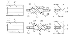
- (A) is sectional drawing which shows the battery module of FIG. 6,
- (b) is sectional drawing which expands and shows a part of FIG. 7 (a).
- (A) is sectional drawing which fractures
- (b) is sectional drawing which expands and shows the fastening member of Fig.8 (a).
- (A), (b) and (c) is sectional drawing which shows the fastening member of a modification.
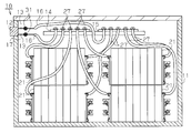
- the battery pack 10 has a housing 11.
- a plurality of battery modules 21 are accommodated in the housing 11.
- the housing 11 is provided with a connector 12 to which an external connection device (for example, a charger or a load) is connected.
- a plurality (two in this embodiment) of output harnesses 13 are connected to the connector 12.
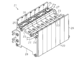
- each battery module 21 includes a plurality of battery holders 22 and a plurality of battery cells 23.
- Each battery cell 23 is held by a corresponding battery holder 22 and has a positive electrode terminal 24 and a negative electrode terminal 25.
- the battery cells 23 are arranged in a line, and the battery module 21 includes end plates 28 that restrain the battery cells 23 at both ends in the arrangement direction of the battery cells 23.
- the positive electrode terminal 24 of one battery cell 23 and the negative electrode terminal 25 of the other battery cell 23 are arranged adjacent to each other, and the adjacent positive electrode terminal 24 and negative electrode terminal are arranged. 25 are connected by a bus bar 26, whereby the battery cells 23 are connected in series.
- a connection harness 27 is connected to each battery cell 23 arranged at both ends in the arrangement direction.
- a first terminal block 14 and a second terminal block 15 are provided inside the housing 11.
- Two connection harnesses 27 extending from each battery module 21 are connected to the first terminal block 14 and the second terminal block 15, respectively.
- a connection harness 27 having the same polarity is connected to each of the terminal blocks 14 and 15, whereby a plurality of battery modules 21 are connected in parallel.
- a harness 16 that is electrically connected to the output harness 13 is connected to each of the terminal blocks 14 and 15.
- Each harness 16 is electrically connected to the output harness 13 by being fixed in a state of being in contact with the output harness 13 by a fastening member 31 provided inside the housing 11.
- the harness 16 is electrically connected to the battery cell 23 via the terminal blocks 14 and 15 and the connection harness 27.
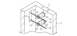
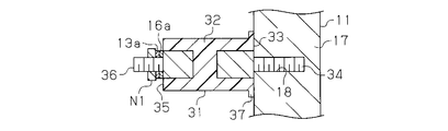
- the fastening member 31 has a column member 32 having a hexagonal column shape. As shown in FIG. 4, the column member 32 has a first end 33 and a second end 35 in the axial direction. The first end 33 is provided with a first screw 34. A second screw 36 is provided at the second end portion 35.
- the column member 32 is made of resin, and the first screw 34 and the second screw 36 are made of metal.
- the first screw 34 is insulated from the second screw 36 by the column member 32.
- the axial length of the first screw 34 is longer than the axial length of the second screw 36.
- An annular projecting portion 37 projecting in a direction intersecting with the axial direction of the fastening member 31 (specifically, a radial direction of the fastening member 31) is provided on the first end 33 of the fastening member 31 on the entire circumference of the column member 32. It is provided over.
- the first screw 34 is configured to be fastened to the first body to be fastened, that is, the wall portion 17 of the housing 11, and the first screw 34 is fastened to the wall portion 17. Then, the second screw 36 protrudes into the housing 11.
- the wall portion 17 of the housing 11 has a screw hole 18, and a female screw is formed on the inner peripheral surface of the screw hole 18.
- the first screw 34 is fastened to the wall portion 17 by screwing the first screw 34 into the screwing hole 18.
- a U-shaped connection fitting 16 a is provided at the end of the harness 16, and a U-shaped connection fitting 13 a is provided at the end of the output harness 13.
- connection fitting 16a of the harness 16 and the connection fitting 13a of the output harness 13 are arranged so as to overlap each other.
- the 2nd to-be-fastened body, ie, nut N1 is fastened by the 2nd screw 36, and both connection metal fittings 13a and 16a are pressed by the nut N1 toward the column member 32, and the output harness 13 and harness 16 It is fixed to the fastening member 31 in an electrically connected state.
- the axial length of the first screw 34 is substantially the same as the depth of the screwing hole 18, and the relationship between the axial length of the first screw 34 and the depth of the screwing hole 18 is fastened by at least vibration or the like. It is determined so that the member 31 does not tilt. If the axial length of the first screw 34 is too long or too short with respect to the depth of the screwing hole 18, the fastening member 31 is easily tilted by vibration. The axial length of the first screw 34 may be longer than the depth of the screw hole 18 as long as the fastening member 31 does not tilt due to vibration or the like.
- the axial length of the second screw 36 is formed to be a length obtained by combining at least the thickness of the connection fitting 13a, the thickness of the connection fitting 16a, and half the axial length of the through hole of the nut N1. ing. If the axial length of the second screw 36 is too long, the projecting length of the second screw 36 becomes long, and there is a risk of hindering the arrangement of the items accommodated in the housing 11. If the axial length of the second screw 36 is shorter than the total length of the thickness of the connection fitting 13a, the thickness of the connection fitting 16a, and half the axial length of the through hole of the nut N1, the nut N1 may come off from the first screw 36.
- the axial length of the second screw 36 is obtained by combining the thickness of the connection fitting 13a, the thickness of the connection fitting 16a, and half the axial length of the through hole of the nut N1 unless the nut N1 is removed. It may be shorter than the length.
- the lengths of the first screw 34 and the second screw 36 are determined so as to satisfy the above conditions, and have different lengths.
- FIG. 5A when the housing 11 and the nut N ⁇ b> 1 are fastened to the fastening member 31, first, the first screw 34 is fastened to the wall portion 17 of the housing 11.
- the jig 41 When the first screw 34 is fastened to the wall portion 17, the jig 41 is fitted into the column member 32 in the axial direction from the second end portion 35, and the jig 41 is rotated. As the jig 41 rotates, the first screw 34 rotates together with the column member 32, so that the first screw 34 is screwed into the screwing hole 18 of the wall portion 17.
- the jig 41 has a hexagonal cylindrical shape. On the inner surface of the jig 41, the diagonal dimension of the hexagon is slightly larger than the diagonal dimension of the hexagonal columnar column member 32 and smaller than the outer diameter of the annular projecting portion 37.
- action of the fastening member 31 of this embodiment is demonstrated.
- the first screw 34 is fastened to the wall portion 17 of the housing 11 using the jig 41.
- the nut N1 is fastened to the second screw 36 to fasten the connection fitting 16 a of the harness 16 and the connection fitting 13 a of the output harness 13. Secure to member 31.
- the following effects can be obtained. (1) Since the overhanging portion 37 restricts the jig 41 from being fitted into the column member 32 from the first end portion 33, the second screw 36 may be fastened to the wall portion 17 of the housing 11. Deterred. Therefore, the nut N1 is erroneously fastened to the first screw 34 and the second screw 36 is prevented from being fastened to the wall portion 17 of the housing 11 by mistake.
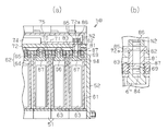
- the battery module 50 includes a plurality of battery holders 51 and a plurality of battery cells 61.
- Each battery cell 61 is held by a corresponding battery holder 22 and has a positive terminal 66 and a negative terminal 67.
- the battery cells 61 are arranged in a line, and the battery module 50 includes end plates 52 at both ends in the arrangement direction of the battery cells 61.
- the battery cell 61 includes a battery case 62 and an electrode assembly 63 accommodated in the battery case 62.
- the battery case 62 includes a cylindrical case body 64 having a bottom wall and an opening, and a flat lid 65 that closes the opening of the case body 64.
- a positive electrode terminal 66 and a negative electrode terminal 67 protrude from the lid 65.
- the positive electrode terminal 66 and the negative electrode terminal 67 each have a shaft portion 68 exposed outside the battery case 62.
- the positive electrode terminal 66 and the negative electrode terminal 67 each have a screw hole 69 extending in the axial direction at the end of the shaft portion 68 exposed from the battery case 62.
- a female screw is formed on the inner peripheral surface of each screw hole 69.
- the positive electrode terminal 66 of one battery cell 61 and the negative electrode terminal 67 of the other battery cell 61 are arranged adjacent to each other, and the adjacent positive electrode terminal 66 and negative electrode terminal are arranged. 67 are connected by a bus bar 70, whereby the battery cells 61 are connected in series.
- the row of battery holders 51 holds a mounting plate 72 on which electronic components and the like are mounted.
- the mounting plate 72 extends in the arrangement direction of the battery cells 61.
- a relay 74 for controlling the discharge of the battery cell 61 and the interruption of the discharge is provided on the mounting plate 72.
- the relay 74 is covered with a rectangular box-shaped relay cover 75.
- a plate-like bus bar 71 connected to the relay 74 is provided in the relay cover 75.
- a battery ECU 77 that controls the battery cell 61 is provided on the mounting plate 72.
- the battery ECU 77 is covered with a rectangular box-shaped ECU cover 78.
- the mounting plate 72 is provided with a through hole 72 a, and one of the two battery cells 61 arranged at both ends in the arrangement direction is one battery cell 61. Is electrically connected to the plate-like bus bar 71 by a fastening member 81 inserted through the through hole 72a.
- the fastening member 81 of the present embodiment includes a hexagonal columnar column member 82 having a first end portion 83 and a second end portion 85 in the axial direction, a first screw 84 provided at the first end portion 83, And a second screw 86 provided at the two end portions 85.
- the column member 82, the first screw 84, and the second screw 86 are all made of metal.
- the axial length of the first screw 84 is longer than the axial length of the second screw 86.
- An annular projecting portion 87 projecting in the radial direction along the end surface of the first end portion 83 is provided at the first end portion 83 of the column member 82.
- the first screw 84 is fastened (screwed) to the screwed hole 69 of the negative terminal 67 of the first object to be fastened, that is, the battery cell 61.
- a second body to be fastened that is, a nut N ⁇ b> 2 is fastened (screwed) to a portion of the second screw 86 protruding from the plate-like bus bar 71.
- the axial length of the first screw 84 is substantially the same as the depth of the screwing hole 69 of the negative electrode terminal 67, and the axial length of the first screw 84 and the depth of the screwing hole 69 are at least vibration or the like. Therefore, the fastening member 81 is determined not to tilt. If the length of the first screw 84 in the axial direction is too long or too short with respect to the depth of the screwing hole 69, the fastening member 81 is easily inclined by vibration. When the axial length of the first screw 84 is too short, the contact area between the first screw 84 and the negative electrode terminal 67 is small, and the resistance value at the contact portion is large.
- the length of the first screw 84 in the axial direction is greater than the depth of the screw hole 69 if the fastening member 81 is not inclined due to vibration or the like and a sufficient contact area between the first screw 84 and the negative electrode terminal 67 can be secured. May be longer or shorter.
- the axial length of the second screw 86 is too long, the height of the relay cover 75 (the length of the side surface of the relay cover 75 extending in parallel to the axial direction of the fastening member 81) increases, and as a result, The dimension of the whole battery module 50 will become large. If the axial length of the second screw 86 is shorter than the combined length of the thickness of the plate-like bus bar 71 and the half of the depth of the through hole of the nut N2, the nut N2 may come off. Therefore, the axial length of the second screw 86 is formed to be a length obtained by combining at least the thickness of the plate-like bus bar 71 and half the depth of the through hole of the nut N2. The axial length of the second screw 86 may be shorter than the combined length of the thickness of the plate-like bus bar 71 and half the depth of the through hole of the nut N2 if the nut N2 is not removed.
- the fastening member 81 of this embodiment will be described.
- the first screw 84 is fastened to the screwing hole 69 of the negative terminal 67 using the same jig 41 as in the first embodiment
- the nut N2 is fastened to the second screw 86.
- the protruding portion 87 restricts the jig 41 from being fitted from the first end portion 83 of the column member 82.
- the protruding portion 87 restricts the fitting of the jig 41 from the first end portion 83, the nut N2 is fastened to the first screw 84, and the second screw 86 is connected to the negative terminal 67. It is deterred from being fastened.
- the battery cell 61 can be electrically connected to the plate-like bus bar 71 by the fastening member 81.
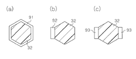
- the shape of the overhanging portion does not have to be annular.
- a projecting portion 91 having a polygonal ring shape such as a hexagonal ring or a projecting portion 92 projecting from a part of the outer periphery of the column members 32 and 82 as shown in FIG. 9 (b). May be.
- projection part 93 which protrudes from several places as a part of outer periphery of the column members 32 and 82 may be sufficient.
- the column members 32 and 82 may have other polygonal shapes such as a pentagonal column shape.
- the overhang portions 37 and 87 may be provided at positions slightly closer to the second end portions 35 and 85 from the first end portions 33 and 83 of the column members 32 and 82.
- the jig 41 may slightly fit into the column members 32 and 82 from the first end portions 33 and 83, but when the jig 41 is rotated, the column members 32 and 82 become the second screws 36.
- , 86 need only be provided with protruding portions 37, 87 at positions where they do not rotate together.
- the overhang portions 37 and 87 only need to restrict the jig 41 from being fitted to the position where the column members 32 and 82 can be rotated from the first end portions 33 and 83. It can be said that the overhang portions 37 and 87 function as a restriction portion that restricts the fastening operation of the jig 41 with respect to the first end portions 33 and 83 of the column members 32 and 82.
- the axial lengths of the first screws 34 and 84 may be shorter than the axial lengths of the second screws 36 and 86.
- the fastening member 81 may be fastened to the positive terminal 66.
Landscapes
- Chemical & Material Sciences (AREA)
- Chemical Kinetics & Catalysis (AREA)
- Electrochemistry (AREA)
- General Chemical & Material Sciences (AREA)
- Engineering & Computer Science (AREA)
- General Engineering & Computer Science (AREA)
- Mechanical Engineering (AREA)
- Connection Of Batteries Or Terminals (AREA)
- Battery Mounting, Suspending (AREA)
Priority Applications (2)
| Application Number | Priority Date | Filing Date | Title |
|---|---|---|---|
| US15/122,762 US10319977B2 (en) | 2014-03-12 | 2015-02-23 | Fastening system with jig restriction flange |
| DE112015001164.1T DE112015001164T5 (de) | 2014-03-12 | 2015-02-23 | Befestigungsbauteil |
Applications Claiming Priority (2)
| Application Number | Priority Date | Filing Date | Title |
|---|---|---|---|
| JP2014-048779 | 2014-03-12 | ||
| JP2014048779A JP6369059B2 (ja) | 2014-03-12 | 2014-03-12 | 締結部材 |
Publications (1)
| Publication Number | Publication Date |
|---|---|
| WO2015137097A1 true WO2015137097A1 (ja) | 2015-09-17 |
Family
ID=54071546
Family Applications (1)
| Application Number | Title | Priority Date | Filing Date |
|---|---|---|---|
| PCT/JP2015/054910 Ceased WO2015137097A1 (ja) | 2014-03-12 | 2015-02-23 | 締結部材 |
Country Status (4)
| Country | Link |
|---|---|
| US (1) | US10319977B2 (enExample) |
| JP (1) | JP6369059B2 (enExample) |
| DE (1) | DE112015001164T5 (enExample) |
| WO (1) | WO2015137097A1 (enExample) |
Families Citing this family (4)
| Publication number | Priority date | Publication date | Assignee | Title |
|---|---|---|---|---|
| JP6387798B2 (ja) * | 2014-11-11 | 2018-09-12 | 株式会社豊田自動織機 | 支持部材 |
| EP3457455A4 (en) * | 2016-03-16 | 2020-03-11 | Kabushiki Kaisha Toshiba | BATTERY PACK |
| JP6705340B2 (ja) * | 2016-08-30 | 2020-06-03 | 株式会社豊田自動織機 | 電池パック |
| JP6790595B2 (ja) * | 2016-08-30 | 2020-11-25 | 株式会社豊田自動織機 | 電池パック |
Citations (5)
| Publication number | Priority date | Publication date | Assignee | Title |
|---|---|---|---|---|
| JPS5738911U (enExample) * | 1980-08-13 | 1982-03-02 | ||
| JPS6389414U (enExample) * | 1987-07-17 | 1988-06-10 | ||
| JPH11120986A (ja) * | 1997-10-13 | 1999-04-30 | Toyota Motor Corp | バッテリーホルダ用接続プレートおよびその製造方法 |
| JP2004031122A (ja) * | 2002-06-26 | 2004-01-29 | Nissan Motor Co Ltd | セルモジュール |
| JP2006324060A (ja) * | 2005-05-17 | 2006-11-30 | Honda Motor Co Ltd | 蓄電装置 |
Family Cites Families (7)
| Publication number | Priority date | Publication date | Assignee | Title |
|---|---|---|---|---|
| US2437344A (en) * | 1944-10-27 | 1948-03-09 | Herman M Behlmann | Insulator and support for electrically charged fence wires |
| US2444046A (en) * | 1945-06-05 | 1948-06-29 | Jacobs Frank | Coupling terminal unit for storage batteries |
| US3345452A (en) * | 1964-02-27 | 1967-10-03 | Thomas & Betts Corp | Sintered powdered metal connectors |
| JPS5948124B2 (ja) | 1980-08-21 | 1984-11-24 | 工業技術院長 | 沈殿処理装置 |
| JPS6389414A (ja) | 1986-10-03 | 1988-04-20 | Mitsubishi Metal Corp | クロロポリシランの製造方法 |
| JPH05205791A (ja) | 1992-01-30 | 1993-08-13 | Mitsubishi Electric Corp | 大電流配線板 |
| US8748034B2 (en) * | 2011-04-14 | 2014-06-10 | Gs Yuasa International Ltd. | Battery including baffling member including one of projecting portion and recessed portion extending from lid plate |
-
2014
- 2014-03-12 JP JP2014048779A patent/JP6369059B2/ja not_active Expired - Fee Related
-
2015
- 2015-02-23 US US15/122,762 patent/US10319977B2/en not_active Expired - Fee Related
- 2015-02-23 DE DE112015001164.1T patent/DE112015001164T5/de not_active Ceased
- 2015-02-23 WO PCT/JP2015/054910 patent/WO2015137097A1/ja not_active Ceased
Patent Citations (5)
| Publication number | Priority date | Publication date | Assignee | Title |
|---|---|---|---|---|
| JPS5738911U (enExample) * | 1980-08-13 | 1982-03-02 | ||
| JPS6389414U (enExample) * | 1987-07-17 | 1988-06-10 | ||
| JPH11120986A (ja) * | 1997-10-13 | 1999-04-30 | Toyota Motor Corp | バッテリーホルダ用接続プレートおよびその製造方法 |
| JP2004031122A (ja) * | 2002-06-26 | 2004-01-29 | Nissan Motor Co Ltd | セルモジュール |
| JP2006324060A (ja) * | 2005-05-17 | 2006-11-30 | Honda Motor Co Ltd | 蓄電装置 |
Also Published As
| Publication number | Publication date |
|---|---|
| US20170069899A1 (en) | 2017-03-09 |
| JP2015172411A (ja) | 2015-10-01 |
| DE112015001164T5 (de) | 2016-11-24 |
| JP6369059B2 (ja) | 2018-08-08 |
| US10319977B2 (en) | 2019-06-11 |
Similar Documents
| Publication | Publication Date | Title |
|---|---|---|
| JP6327072B2 (ja) | 電池モジュール | |
| JP5870445B2 (ja) | アース機能付パイプ取付具 | |
| WO2015137097A1 (ja) | 締結部材 | |
| JP6233654B2 (ja) | 配線モジュール | |
| US10485121B2 (en) | Electrical connection box and wire harness | |
| WO2013084713A1 (ja) | 電池配線モジュール | |
| WO2016035601A1 (ja) | 配線モジュールおよび配線モジュールの製造方法 | |
| WO2015015667A1 (ja) | 配線モジュール | |
| JP6108177B2 (ja) | 配線モジュール | |
| WO2016047477A1 (ja) | 配線モジュール | |
| JP2013143395A (ja) | 蓄電モジュール | |
| JP5924639B2 (ja) | ターミナルカバー | |
| JP2016038933A5 (enExample) | ||
| JP2018198156A (ja) | バッテリーターミナル | |
| WO2014136929A1 (ja) | 電池モジュール | |
| US11118619B2 (en) | Connection assembly | |
| WO2016009786A1 (ja) | 蓄電装置 | |
| JP2015172411A5 (enExample) | ||
| WO2016031558A1 (ja) | 電池モジュール | |
| JP5790742B2 (ja) | 電池接続アセンブリ | |
| JP6318871B2 (ja) | 蓄電装置 | |
| JP2016031915A (ja) | 蓄電モジュール及び蓄電モジュールの防水構造 | |
| JP6308068B2 (ja) | 蓄電装置 | |
| JP6387798B2 (ja) | 支持部材 | |
| JPWO2019245021A1 (ja) | 蓄電装置 |
Legal Events
| Date | Code | Title | Description |
|---|---|---|---|
| 121 | Ep: the epo has been informed by wipo that ep was designated in this application |
Ref document number: 15760890 Country of ref document: EP Kind code of ref document: A1 |
|
| WWE | Wipo information: entry into national phase |
Ref document number: 15122762 Country of ref document: US |
|
| WWE | Wipo information: entry into national phase |
Ref document number: 112015001164 Country of ref document: DE |
|
| 122 | Ep: pct application non-entry in european phase |
Ref document number: 15760890 Country of ref document: EP Kind code of ref document: A1 |