WO2015015667A1 - 配線モジュール - Google Patents
配線モジュール Download PDFInfo
- Publication number
- WO2015015667A1 WO2015015667A1 PCT/JP2013/084069 JP2013084069W WO2015015667A1 WO 2015015667 A1 WO2015015667 A1 WO 2015015667A1 JP 2013084069 W JP2013084069 W JP 2013084069W WO 2015015667 A1 WO2015015667 A1 WO 2015015667A1
- Authority
- WO
- WIPO (PCT)
- Prior art keywords
- electric wire
- insulating cover
- wire guide
- cover
- wiring module
- Prior art date
Links
Images

Classifications
-
- B—PERFORMING OPERATIONS; TRANSPORTING
- B60—VEHICLES IN GENERAL
- B60L—PROPULSION OF ELECTRICALLY-PROPELLED VEHICLES; SUPPLYING ELECTRIC POWER FOR AUXILIARY EQUIPMENT OF ELECTRICALLY-PROPELLED VEHICLES; ELECTRODYNAMIC BRAKE SYSTEMS FOR VEHICLES IN GENERAL; MAGNETIC SUSPENSION OR LEVITATION FOR VEHICLES; MONITORING OPERATING VARIABLES OF ELECTRICALLY-PROPELLED VEHICLES; ELECTRIC SAFETY DEVICES FOR ELECTRICALLY-PROPELLED VEHICLES
- B60L50/00—Electric propulsion with power supplied within the vehicle
- B60L50/50—Electric propulsion with power supplied within the vehicle using propulsion power supplied by batteries or fuel cells
- B60L50/60—Electric propulsion with power supplied within the vehicle using propulsion power supplied by batteries or fuel cells using power supplied by batteries
- B60L50/64—Constructional details of batteries specially adapted for electric vehicles
-
- B—PERFORMING OPERATIONS; TRANSPORTING
- B60—VEHICLES IN GENERAL
- B60L—PROPULSION OF ELECTRICALLY-PROPELLED VEHICLES; SUPPLYING ELECTRIC POWER FOR AUXILIARY EQUIPMENT OF ELECTRICALLY-PROPELLED VEHICLES; ELECTRODYNAMIC BRAKE SYSTEMS FOR VEHICLES IN GENERAL; MAGNETIC SUSPENSION OR LEVITATION FOR VEHICLES; MONITORING OPERATING VARIABLES OF ELECTRICALLY-PROPELLED VEHICLES; ELECTRIC SAFETY DEVICES FOR ELECTRICALLY-PROPELLED VEHICLES
- B60L50/00—Electric propulsion with power supplied within the vehicle
- B60L50/50—Electric propulsion with power supplied within the vehicle using propulsion power supplied by batteries or fuel cells
- B60L50/60—Electric propulsion with power supplied within the vehicle using propulsion power supplied by batteries or fuel cells using power supplied by batteries
- B60L50/66—Arrangements of batteries
-
- B—PERFORMING OPERATIONS; TRANSPORTING
- B60—VEHICLES IN GENERAL
- B60R—VEHICLES, VEHICLE FITTINGS, OR VEHICLE PARTS, NOT OTHERWISE PROVIDED FOR
- B60R16/00—Electric or fluid circuits specially adapted for vehicles and not otherwise provided for; Arrangement of elements of electric or fluid circuits specially adapted for vehicles and not otherwise provided for
- B60R16/02—Electric or fluid circuits specially adapted for vehicles and not otherwise provided for; Arrangement of elements of electric or fluid circuits specially adapted for vehicles and not otherwise provided for electric constitutive elements
- B60R16/0207—Wire harnesses
- B60R16/0215—Protecting, fastening and routing means therefor
-
- H—ELECTRICITY
- H01—ELECTRIC ELEMENTS
- H01M—PROCESSES OR MEANS, e.g. BATTERIES, FOR THE DIRECT CONVERSION OF CHEMICAL ENERGY INTO ELECTRICAL ENERGY
- H01M10/00—Secondary cells; Manufacture thereof
- H01M10/42—Methods or arrangements for servicing or maintenance of secondary cells or secondary half-cells
- H01M10/48—Accumulators combined with arrangements for measuring, testing or indicating the condition of cells, e.g. the level or density of the electrolyte
- H01M10/482—Accumulators combined with arrangements for measuring, testing or indicating the condition of cells, e.g. the level or density of the electrolyte for several batteries or cells simultaneously or sequentially
-
- H—ELECTRICITY
- H01—ELECTRIC ELEMENTS
- H01M—PROCESSES OR MEANS, e.g. BATTERIES, FOR THE DIRECT CONVERSION OF CHEMICAL ENERGY INTO ELECTRICAL ENERGY
- H01M50/00—Constructional details or processes of manufacture of the non-active parts of electrochemical cells other than fuel cells, e.g. hybrid cells
- H01M50/50—Current conducting connections for cells or batteries
- H01M50/502—Interconnectors for connecting terminals of adjacent batteries; Interconnectors for connecting cells outside a battery casing
- H01M50/503—Interconnectors for connecting terminals of adjacent batteries; Interconnectors for connecting cells outside a battery casing characterised by the shape of the interconnectors
-
- H—ELECTRICITY
- H02—GENERATION; CONVERSION OR DISTRIBUTION OF ELECTRIC POWER
- H02G—INSTALLATION OF ELECTRIC CABLES OR LINES, OR OF COMBINED OPTICAL AND ELECTRIC CABLES OR LINES
- H02G3/00—Installations of electric cables or lines or protective tubing therefor in or on buildings, equivalent structures or vehicles
- H02G3/02—Details
- H02G3/04—Protective tubing or conduits, e.g. cable ladders or cable troughs
- H02G3/0406—Details thereof
- H02G3/0418—Covers or lids; Their fastenings
-
- H—ELECTRICITY
- H02—GENERATION; CONVERSION OR DISTRIBUTION OF ELECTRIC POWER
- H02G—INSTALLATION OF ELECTRIC CABLES OR LINES, OR OF COMBINED OPTICAL AND ELECTRIC CABLES OR LINES
- H02G3/00—Installations of electric cables or lines or protective tubing therefor in or on buildings, equivalent structures or vehicles
- H02G3/02—Details
- H02G3/04—Protective tubing or conduits, e.g. cable ladders or cable troughs
- H02G3/0437—Channels
-
- B—PERFORMING OPERATIONS; TRANSPORTING
- B60—VEHICLES IN GENERAL
- B60L—PROPULSION OF ELECTRICALLY-PROPELLED VEHICLES; SUPPLYING ELECTRIC POWER FOR AUXILIARY EQUIPMENT OF ELECTRICALLY-PROPELLED VEHICLES; ELECTRODYNAMIC BRAKE SYSTEMS FOR VEHICLES IN GENERAL; MAGNETIC SUSPENSION OR LEVITATION FOR VEHICLES; MONITORING OPERATING VARIABLES OF ELECTRICALLY-PROPELLED VEHICLES; ELECTRIC SAFETY DEVICES FOR ELECTRICALLY-PROPELLED VEHICLES
- B60L2240/00—Control parameters of input or output; Target parameters
- B60L2240/40—Drive Train control parameters
- B60L2240/54—Drive Train control parameters related to batteries
- B60L2240/545—Temperature
-
- B—PERFORMING OPERATIONS; TRANSPORTING
- B60—VEHICLES IN GENERAL
- B60L—PROPULSION OF ELECTRICALLY-PROPELLED VEHICLES; SUPPLYING ELECTRIC POWER FOR AUXILIARY EQUIPMENT OF ELECTRICALLY-PROPELLED VEHICLES; ELECTRODYNAMIC BRAKE SYSTEMS FOR VEHICLES IN GENERAL; MAGNETIC SUSPENSION OR LEVITATION FOR VEHICLES; MONITORING OPERATING VARIABLES OF ELECTRICALLY-PROPELLED VEHICLES; ELECTRIC SAFETY DEVICES FOR ELECTRICALLY-PROPELLED VEHICLES
- B60L2240/00—Control parameters of input or output; Target parameters
- B60L2240/40—Drive Train control parameters
- B60L2240/54—Drive Train control parameters related to batteries
- B60L2240/547—Voltage
-
- B—PERFORMING OPERATIONS; TRANSPORTING
- B60—VEHICLES IN GENERAL
- B60L—PROPULSION OF ELECTRICALLY-PROPELLED VEHICLES; SUPPLYING ELECTRIC POWER FOR AUXILIARY EQUIPMENT OF ELECTRICALLY-PROPELLED VEHICLES; ELECTRODYNAMIC BRAKE SYSTEMS FOR VEHICLES IN GENERAL; MAGNETIC SUSPENSION OR LEVITATION FOR VEHICLES; MONITORING OPERATING VARIABLES OF ELECTRICALLY-PROPELLED VEHICLES; ELECTRIC SAFETY DEVICES FOR ELECTRICALLY-PROPELLED VEHICLES
- B60L2240/00—Control parameters of input or output; Target parameters
- B60L2240/40—Drive Train control parameters
- B60L2240/54—Drive Train control parameters related to batteries
- B60L2240/549—Current
-
- H—ELECTRICITY
- H01—ELECTRIC ELEMENTS
- H01M—PROCESSES OR MEANS, e.g. BATTERIES, FOR THE DIRECT CONVERSION OF CHEMICAL ENERGY INTO ELECTRICAL ENERGY
- H01M2220/00—Batteries for particular applications
- H01M2220/20—Batteries in motive systems, e.g. vehicle, ship, plane
-
- H—ELECTRICITY
- H01—ELECTRIC ELEMENTS
- H01M—PROCESSES OR MEANS, e.g. BATTERIES, FOR THE DIRECT CONVERSION OF CHEMICAL ENERGY INTO ELECTRICAL ENERGY
- H01M50/00—Constructional details or processes of manufacture of the non-active parts of electrochemical cells other than fuel cells, e.g. hybrid cells
- H01M50/50—Current conducting connections for cells or batteries
- H01M50/502—Interconnectors for connecting terminals of adjacent batteries; Interconnectors for connecting cells outside a battery casing
- H01M50/514—Methods for interconnecting adjacent batteries or cells
- H01M50/517—Methods for interconnecting adjacent batteries or cells by fixing means, e.g. screws, rivets or bolts
-
- Y—GENERAL TAGGING OF NEW TECHNOLOGICAL DEVELOPMENTS; GENERAL TAGGING OF CROSS-SECTIONAL TECHNOLOGIES SPANNING OVER SEVERAL SECTIONS OF THE IPC; TECHNICAL SUBJECTS COVERED BY FORMER USPC CROSS-REFERENCE ART COLLECTIONS [XRACs] AND DIGESTS
- Y02—TECHNOLOGIES OR APPLICATIONS FOR MITIGATION OR ADAPTATION AGAINST CLIMATE CHANGE
- Y02E—REDUCTION OF GREENHOUSE GAS [GHG] EMISSIONS, RELATED TO ENERGY GENERATION, TRANSMISSION OR DISTRIBUTION
- Y02E60/00—Enabling technologies; Technologies with a potential or indirect contribution to GHG emissions mitigation
- Y02E60/10—Energy storage using batteries
-
- Y—GENERAL TAGGING OF NEW TECHNOLOGICAL DEVELOPMENTS; GENERAL TAGGING OF CROSS-SECTIONAL TECHNOLOGIES SPANNING OVER SEVERAL SECTIONS OF THE IPC; TECHNICAL SUBJECTS COVERED BY FORMER USPC CROSS-REFERENCE ART COLLECTIONS [XRACs] AND DIGESTS
- Y02—TECHNOLOGIES OR APPLICATIONS FOR MITIGATION OR ADAPTATION AGAINST CLIMATE CHANGE
- Y02T—CLIMATE CHANGE MITIGATION TECHNOLOGIES RELATED TO TRANSPORTATION
- Y02T10/00—Road transport of goods or passengers
- Y02T10/60—Other road transportation technologies with climate change mitigation effect
- Y02T10/70—Energy storage systems for electromobility, e.g. batteries
Definitions
- the present invention relates to a wiring module.
- a power storage module for an electric vehicle or a hybrid vehicle has a plurality of power storage elements each having a positive electrode electrode and a negative electrode terminal, and a plurality of power storage elements connected by connecting members between the electrode terminals of the power storage elements. Are connected in series or in parallel.
- Patent Document 1 describes a battery connecting member including a terminal for connecting between electrodes of a plurality of batteries and a case for housing the terminals.
- the central connecting portion for connecting the right block and the left block is an insulating cover portion having an electric wire guide portion on the outer surface side, a temporary locking cover portion covering a part of the open surface of the electric wire guide portion, A main locking cover portion covering the entire open surface of the wire guide portion is integrally provided.
- the temporary locking cover part has a locking claw, and this locking claw is locked to the locked part formed in the insulating cover part.
- the present invention has been completed based on the above circumstances, and an object thereof is to provide a wiring module capable of suppressing a decrease in insulation.
- the present invention includes a connection member that connects adjacent electrode terminals in a plurality of power storage elements having positive and negative electrode terminals, and an insulation protector that houses the connection member, wherein the insulation protector includes the connection A main body that holds the member; an insulating cover that is movably supported in a closed position that covers the connection member; and an electric wire passage portion that is superimposed on at least a part of the insulating cover in the closed position and through which an electric wire is passed.
- a wiring module comprising an electric wire guide.
- the wire guide having the wire passing portion is overlapped on at least a part of the insulating cover, the die hole or the like in the insulating cover is compared with the configuration in which the wire is temporarily locked to the insulating cover. Since it is not necessary to form a configuration for temporarily locking the electric wire, it is possible to suppress a decrease in insulation.
- the electric wire guide is provided with the holding piece for hold
- the holding piece for holding the electric wire is formed, there is a concern that the insulating property is lowered due to the hole for forming the holding piece. According to this configuration, even in such a case, the insulating cover Since the electric wire guide is piled up, it becomes possible to suppress the insulation fall.
- the insulating cover and the wire guide are connected to the opposite side of the main body with the connection member interposed therebetween.
- the top view which shows the electrical storage module provided with the wiring module of Embodiment 1.
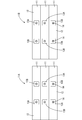
- Plan view showing a plurality of power storage element groups Top view showing the wiring module with the insulating cover open
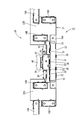
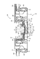
- Top view showing the wiring module with the insulating cover closed
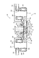
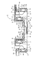
- Top view showing the wiring module with the wire guide closed
- the top view which shows the wiring module of the state which wired the electric wire from the state of FIG.
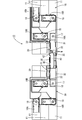
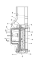
- Top view showing the wiring module with the wire cover closed AA sectional view of FIG.
- the wiring module 15 of the present embodiment is attached to a plurality of power storage elements 11 arranged in a row (six in the present embodiment are illustrated) to constitute the power storage module 10.
- the power storage module 10 is used as a drive source for a vehicle such as an electric vehicle or a hybrid vehicle.
- a vehicle such as an electric vehicle or a hybrid vehicle.
- the upper side in FIG. 1 is the front
- the lower side is the rear
- the left-right direction is based on the direction in FIG. 1
- the vertical direction is described with the front side in FIG. To do.
- the power storage module 10 includes a plurality of power storage elements 11 and a wiring module 15 (illustrated by omitting the left and right end portions in FIG. 1) attached to the plurality of power storage elements 11.
- each power storage element 11 has a flat shape with a short diameter in the front-rear direction and a long diameter in the left-right direction, and three power storage element groups 11 ⁇ / b> A and 11 ⁇ / b> B arranged in the front-rear direction (short diameter direction). They are arranged side by side in the left-right direction (major axis direction) at intervals.
- the power storage element 11 has electrode terminals 13A and 13B (illustrated as a positive electrode 13A and a negative electrode 13B) protruding vertically from an end face of a flat rectangular parallelepiped body portion 12 in which a power storage element (not shown) is accommodated.
- electrode terminals 13A and 13B illustrated as a positive electrode 13A and a negative electrode 13B protruding vertically from an end face of a flat rectangular parallelepiped body portion 12 in which a power storage element (not shown) is accommodated.
- the electrode terminals 13A and 13B are nuts having screw holes 14, and the outer periphery thereof is covered with a synthetic resin.
- the polarity (positive / negative) direction of each power storage element 11 is arranged so that the electrode terminals 13A and 13B of the power storage elements 11 adjacent to each other are reversed, whereby the electrode terminals 13A and 13B having different polarities are adjacent to each other. It is configured to fit.
- the plurality of power storage elements 11 are fixed by a holding plate (not shown).
- the wiring module 15 includes a plurality of connection members 16A and 16B that connect the electrode terminals 13A and 13B of the adjacent power storage elements 11, a voltage detection terminal 18 that is superimposed on the connection member 16B, and a plurality of connection members 16A and 13B. And an insulating protector 20 that holds the connection members 16A and 16B and the voltage detection terminal 18.
- connection members 16A and 16B are made of two types of metal plate materials having different lengths, and the distance between the electrode terminals 13A and 13B is long, and the distance between the electrode terminals 13A and 13B is long.
- a short connecting member 16B connected in a short front-rear direction.
- connection members 16A and 16B are both formed by pressing a metal plate made of copper, copper alloy, stainless steel (SUS), aluminum, or the like into a predetermined shape. Metals such as tin and nickel are plated on the surfaces of the connecting members 16A and 16B.
- a pair of substantially circular insertion holes 17, 17 are formed through the connection members 16A, 16B. The insertion holes 17 and 17 are arranged so as to be continuous with the screw holes 14 of the electrode terminals 13A and 13B, and a shaft portion of a bolt (not shown) is inserted and fastened so that the adjacent electrode terminals 13A and 13B are connected. Are electrically connected via the connecting members 16A and 16B.
- the voltage detection terminal 18 is made of a rectangular metal plate material, and an electric wire connection portion 19 connected to the terminal portion of the electric wire W is integrally formed.
- a circular insertion hole 18 ⁇ / b> A is formed through the voltage detection terminal 18.
- the voltage detection terminal 18 is arranged so that the axis of the electric wire W connected to the electric wire connection portion 19 is inclined with respect to the direction orthogonal to the connection direction of the connection member 16B.
- the electric wire W is connected to a battery ECU (not shown).
- This battery ECU is equipped with a microcomputer, an element, and the like, and has a function for detecting voltage, current, temperature, etc. of the storage element 11 and controlling charge / discharge of each storage element 11. Of the configuration.
- the insulating protector 20 is made of an insulating synthetic resin, and as shown in FIG. 3, a main body 21 that holds the connecting members 16A and 16B, and a closed body that is formed integrally with the main body 21 and covers the long connecting member 16A. Insulating cover 31 that can be rotated to a position (in FIG. 3, the insulating cover 31 shows an open state in which the long connecting member 16A is not covered), and an electric wire guide that is superimposed on an intermediate portion of the insulating cover 31 disposed in the closed position. 35.
- the main body 21 includes a pair of left and right mounting portions 22A and 22B mounted on the left and right power storage element groups 11A and 11B, and a connecting portion 23 that connects the left and right mounting portions 22A and 22B.
- the main body 21 is configured by connecting two divided members that can be divided into left and right at the connecting portion 23.
- the main body 21 includes a connection member holding portion 24A that holds the long connection member 16A and a connection member holding portion 24B that holds the short connection member 16B.
- the connecting member holding portions 24A and 24B are both erected on the bottom plate 25 along the flat bottom plate 25 on which the connecting members 16A and 16B are placed (see FIG. 8) and the peripheral edges of the connecting members 16A and 16B.
- a partition wall 26 that separates the connection members 16A and 16B from the outside in an insulated state.
- Opening portions (not shown) through which the upper ends of the electrode terminals 13A and 13B are inserted are formed on the back surfaces of the connection member holding portions 24A and 24B.
- the partition wall 26 is formed with a plurality of pressing pieces 27 that protrude inward of the partition wall 26 and prevent the connecting members 16 ⁇ / b> A and 16 ⁇ / b> B from coming out upward.
- a second locked portion 38 is formed on the partition wall 26 of the connecting member holding portion 24A that holds the long connecting member 16A, the auxiliary cover portion 30, the insulating cover 31, and the locked portion 30B that locks the wire guide 35 in the closed position.
- the locked portions 30 ⁇ / b> B and 34 are arranged side by side on the front side of the partition wall 26, and the second locked portion 38 is arranged on the rear side of the partition wall 26.
- Locking holes 30C, 34A, and 38A are formed through the locked portion 30B, the first locked portion 34, and the second locked portion 38.
- the locking holes 30C, 34A, and 38A have an oval shape that is long in the left-right direction.
- the auxiliary cover part 30 which covers the electric wire W routed along the long connection member 16A is connected to the electric wire wiring part 28 in front of the long connection member 16A in the main body 21 via the hinge part 30D. Yes.
- a locking piece 30A protrudes from the tip of the auxiliary cover portion 30.
- the locking piece 30A is locked to the edge of the locking hole 30C of the locked portion 30B in the main body 21, and the auxiliary cover portion. 30 is held in a closed position covering the electric wire W of the electric wire routing portion 28.
- the electric wire routing portion 28 is formed in a region of the main body 21 other than the connection member holding portions 24A and 24B, and the electric wires W are routed together on the edge side of the main body 21.
- a separation regulating piece 29 that regulates the separation of the electric wire W extends in a direction along the plate surface of the electric wire routing portion 28.
- the insulating cover 31 has a plate shape that is long in the left-right direction, and is provided with a length that covers substantially the entire portion of the long connecting member 16A except for the end in the left-right direction.
- One hinge portion 32 is connected.
- the first hinge portion 32 is flexible by being formed in a thin strip shape, and is formed integrally with the main body 21 and the insulating cover 31, and has a plurality (three in this embodiment) spaced in the left-right direction. ) Is provided. A plurality of (five in the present embodiment) first locking portions 33 are formed on the edge of the insulating cover 31 opposite to the first hinge portion 32 with a space in the left-right direction.
- the first locking portion 33 protrudes in a direction rising from the plate surface of the insulating cover 31, has a locking claw at the tip, and can be bent and deformed in the front-rear direction.
- the first locking portion 33 is inserted into the locking hole 34A of the connecting member holding portion 24A when the insulating cover 31 is put on the connecting member holding portion 24A to set the closed position to cover the long connecting member 16A. Is locked to the hole edge of the locking hole 34A. Thereby, the 1st latching
- the wire guide 35 is a plate having a shorter length than the insulating cover 31 and long in the left-right direction, covers the intermediate part side of the insulating cover 31, and does not cover the both end parts side of the insulating cover 31 in the left-right direction.
- the electric wire guide 35 is connected to the front end portion of the connection member holding portion 24 ⁇ / b> A via the second hinge portion 36.
- the second hinge portion 36 can be flexibly deformed by being formed with a thin thickness, and is formed integrally with the wire guide 35 and the connection member holding portion 24A.
- the second hinge portion 36 is connected to the side opposite to the insulating cover 31 with the connection member holding portion 24A holding the long connection member 16A interposed therebetween, and the wire guide 35 is connected to the main body by the second hinge portion 36. 21 can be rotated.
- the electric wire passing part 37 through which the electric wire W is passed is provided.
- the wire passage portion 37 has a groove shape extending in the left-right direction, and a holding piece 35A protrudes inward from the upper end portions of the groove walls 37B and 37B rising from both sides of the groove bottom 37A.
- the holding piece 35 ⁇ / b> A regulates the detachment of the electric wire W from the electric wire passage portion 37.
- a die hole 35B for forming the holding piece 35A by a die is formed in the groove bottom 37A.
- a plurality of second locking portions 39 are formed at the end of the wire guide 35 opposite to the second hinge portion 36.
- locking part 39 protrudes in the direction orthogonal to the plate surface of the electric wire guide 35, has a latching claw in a front-end
- the second locking portion 39 covers the second guide portion of the connecting member holding portion 24A when the wire guide 35 is placed in the closed position by covering the wire guide 35 so as to overlap the upper surface of the insulating cover 31 in the closed position.
- the wire guide 35 is held in the closed position by being inserted into the locking hole 38A penetrating through 38 and the locking claw being locked to the hole edge of the locking hole 38A.
- An electric wire cover 40 that covers the electric wire passage portion 37 is connected to the electric wire guide 35.
- the wire cover 40 is connected to the wire guide 35 via a plurality of third hinge portions 41 provided on the side edge of the wire guide 35 opposite to the second hinge portion 36.
- the third hinge portion 41 is a band-shaped member formed integrally with the wire cover 40 and the wire guide 35, and can be flexibly deformed by being formed with a thin thickness.
- a third locking portion 42 is formed on the side edge of the electric wire cover 40 opposite to the third hinge portion 41.
- locking part 42 protrudes in the direction orthogonal to the plate
- the third locking portion 42 is formed in a locking hole 43A that penetrates the third locked portion 43 of the wire guide 35 when the wire cover 40 is put on the wire guide 35 to be in the closed position.
- the electric wire cover 40 is held in the closed position by being inserted and locked to the hole edge of the locking hole 43A.
- the connecting members 16A and 16B are accommodated in the connecting member holding portions 24A and 24B of the insulating protector 20 with the insulating covers 31 and 35 open (FIG. 3).
- the insulating cover 31 is rotated about the first hinge portion 32 to the side facing the long connecting member 16A, and the first locking portion 33 is set to a closed position that covers the long connecting member 16A.
- the first locked portion 34 is locked (FIG. 4).
- the wire guide 35 is turned to the side facing the insulating cover 31 with the second hinge portion 36 as an axis so that the wire guide 35 is in a closed position covering the insulating cover 31, and the second locking portion 39 is set to the second covered portion.
- the locking portion 38 is locked (FIG. 5).
- the voltage detection terminal 18 connected to the terminal portion of the electric wire W is mounted so as to overlap the short connection member 16B, and the electric wire W is routed to the electric wire routing portion 28 and guided to an external battery ECU or the like (FIG. 6). .
- the electric wire W on the mounting portion 22A side is guided to the mounting portion 22B side so as to be along the long connecting member 16A, but the intermediate portion side of the long connecting member 16A is an electric wire. W is passed from the electric wire routing portion 28 on the side of the long connecting member 16A so as to bypass the electric wire passing portion 37 of the electric wire guide 35 arranged on the upper side of the long connecting member 16A.
- the electric wire cover 40 is turned to the side facing the electric wire guide 35 with the third hinge portion 41 as an axis, the electric wire cover 40 is set to a closed position covering the electric wire passage portion 37, and the third locking portion 42 is set to the third covered portion.
- the locking portion 43 is locked.
- the auxiliary cover part 30 is rotated to the closed position which covers the electric wire W (FIG. 7). Thereby, the wiring module 15 is formed.
- the power storage module 10 is formed by mounting the wiring module 15 on the plurality of power storage elements 11 and fastening them to the electrode terminals 13A and 13B through bolts through the insertion holes 17 and 17 of the connection members 16A and 16B.
- the wiring module 15 includes a connecting member 16A that connects the adjacent electrode terminals 13A and 13B in the plurality of power storage elements 11 having the positive and negative electrode terminals 13A and 13B, and an insulating protector that houses the connecting member 16A.
- the insulating protector 20 includes a main body 21 that holds the connecting member 16A, an insulating cover 31 that is movably supported in a closed position that covers the connecting member 16A, and an intermediate portion (at least an insulating cover 31 in the closed position). And a wire guide 35 having a wire passage portion 37 through which the wire W is passed.
- a temporary locking cover portion that has a wire guide portion on the outer surface of the insulating cover and has a locking claw locked to the insulating cover and covers a part of the open surface of the wire guide portion.
- the main locking cover portion that covers the entire open surface of the wire guide portion are integrated, the connection member is insulated from the outside only by the insulating cover, so there is a concern that the insulation may deteriorate.
- the size is increased by the provision of the temporary locking cover portion on the insulating cover.
- the wire guide 35 having the wire passage portion 37 through which the wire W is passed is overlapped on at least a part of the insulating cover 31, the wire is temporarily locked to the insulating cover through the wire. Since it is not necessary to form a structure for temporarily locking an electric wire such as a die hole in the insulating cover as compared with the structure, it is possible to suppress a decrease in insulation. Further, since the wire guide 35 is made of an insulating member, it is possible to suppress a decrease in insulation as compared with a configuration in which the connection member 16A is insulated from the outside only by the insulating cover 31. Furthermore, since the electric wire is held without providing the temporary locking cover portion, the configuration can be simplified and the size can be reduced as compared with the provisional locking cover portion.
- the electric wire guide 35 includes a holding piece 35A for holding the electric wire W in the electric wire passage portion 37, and a hole 35B for forming the holding piece 35A.
- a holding piece 35A for holding the electric wire W is formed, there is a concern about a decrease in insulation due to the hole 35B for forming the holding piece 35A.
- the wire guide 35 is superimposed on the insulating cover 31, it is possible to suppress a decrease in insulation.
- the present invention is not limited to the embodiments described with reference to the above description and drawings.
- the following embodiments are also included in the technical scope of the present invention.
- the electric wire guide 35 is superimposed on the intermediate part of the insulating cover 31, it is not restricted to this.
- the wire guide 35 may be overlapped on one side of the insulating cover 31 in the left-right direction. Further, the wire guide 35 may be overlapped over the entire insulating cover 31.
- the insulating cover 31 and the wire guide 35 are arranged on the opposite side across the connecting member 16A, the insulating cover 31 and the wire guide 35 may be provided on the same side with respect to the connecting member 16A. In this case, for example, the insulating cover 31 and the wire guide 35 may be connected via a hinge portion.
- the power storage element 11 is an example of a battery, the power storage element 11 may be a capacitor or the like.
- the number of power storage elements 11 is not limited to the number in the above embodiment, and can be changed as appropriate. Further, the configuration of the wiring module can be changed as appropriate according to the number of power storage elements 11.
- the connecting members 16A and 16B are both formed by pressing a metal plate made of copper, copper alloy, stainless steel (SUS), aluminum or the like into a predetermined shape, and the surface thereof is tin. It is not necessary to perform plating with a metal such as nickel.
- Power storage module 11 Power storage elements 11A, 11B: Power storage element groups 13A, 13B: Electrode terminal 15: Wiring module 16A, 16B: Connection member 18: Voltage detection terminal 20: Insulation protector 21: Body 31: Insulation cover 32: No. 1 hinge portion 33: first locking portion 34: first locked portion 35: electric wire guide 35A: holding piece 35B: punching hole 36: second hinge portion 37: electric wire passage portion 38: second locked portion 39 : Second locking part 40: electric wire cover 41: third hinge part 42: third locking part 43: third locked part W: electric wire
Abstract
Description
・前記電線ガイドは、前記電線を前記電線通し部内に保持するための保持片と、前記保持片を形成するための抜き孔とを備える。
電線を保持するための保持片を形成すると、この保持片を形成するための抜き孔により絶縁性の低下が懸念されるが、本構成によれば、このような場合であっても、絶縁カバーには、電線ガイドが重ねられているため、絶縁性の低下を抑制することが可能になる。
以下、実施形態を図1~図8を参照しつつ説明する。
本実施形態の配線モジュール15は、図1に示すように、複数個(本実施形態では6個を図示)並んで配列された蓄電素子11に取付けられて蓄電モジュール10を構成するものである。蓄電モジュール10は、例えば、電気自動車またはハイブリッド自動車等の車両の駆動源として使用される。以下では、前後方向については図1の上方を前方、下方を後方とし、左右方向については、図1の方向を基準とし、上下方向については、図1の手前側を上方、奥方を下方として説明する。
蓄電モジュール10は、複数個の蓄電素子11と、複数個の蓄電素子11に取付けられる配線モジュール15(図1では、左右の端部側を省略して図示)とを備えて構成されている。
配線モジュール15は、図7に示すように、隣り合う蓄電素子11の電極端子13A,13B間を接続する複数の接続部材16A,16Bと、接続部材16Bに重ねられる電圧検知端子18と、複数の接続部材16A,16B及び電圧検知端子18を保持する絶縁プロテクタ20とを備える。
接続部材16A,16Bは、長さが異なる2種類の金属板材からなり、電極端子13A,13B間の間隔が長い左右方向に接続する長尺接続部材16Aと、電極端子13A,13B間の間隔が短い前後方向に接続する短尺接続部材16Bとを備える。
絶縁プロテクタ20は、絶縁性の合成樹脂製であって、図3に示すように、接続部材16A,16Bを保持する本体21と、本体21と一体に形成され、長尺接続部材16Aを覆う閉鎖位置に回動可能な絶縁カバー31(図3では、絶縁カバー31が長尺接続部材16Aを覆わない開放状態を示す)と、閉鎖位置に配された絶縁カバー31の中間部に重ねられる電線ガイド35とを備える。
本体21は、左右の蓄電素子群11A,11Bのそれぞれに載置される左右一対の載置部22A,22Bと、左右の載置部22A,22B間を連結する連結部23とを有する。なお、本体21は連結部23の部分で左右に分割可能な2個の分割部材を連結して構成されている。
本体21は、長尺接続部材16Aを保持する接続部材保持部24Aと、短尺接続部材16Bを保持する接続部材保持部24Bとを備える。接続部材保持部24A,24Bは、共に、接続部材16A,16Bが載置される平板状の底板25と(図8参照)、接続部材16A,16Bの周縁に沿うように底板25に立設され、接続部材16A,16Bを外部と絶縁状態で隔てる隔壁26とを有する。
絶縁カバー31は、左右方向に長い板状であって、長尺接続部材16Aの左右方向の端部を除いたほぼ全体を覆う長さで設けられ、接続部材保持部24Aの後端部に第1ヒンジ部32を介して接続されている。
絶縁カバー31における第1ヒンジ部32とは反対側の端縁には、左右方向に間隔を空けて複数(本実施形態では5個)の第1係止部33が形成されている。
電線ガイド35は、絶縁カバー31よりも短い長さで左右方向に長い板状であって、絶縁カバー31の中間部側を覆い、絶縁カバー31の左右方向の両端部側は覆わない。電線ガイド35は、第2ヒンジ部36を介して接続部材保持部24Aの前端部に接続されている。第2ヒンジ部36は、薄肉の厚みで形成されることにより撓み変形可能とされ、電線ガイド35及び接続部材保持部24Aと一体に形成されている。
第2ヒンジ部36は、長尺接続部材16Aが保持された接続部材保持部24Aを挟んで絶縁カバー31とは反対側に接続されており、電線ガイド35は、第2ヒンジ部36により、本体21に対して回動可能となっている。
電線カバー40の第3ヒンジ部41とは反対側の側縁には、第3係止部42が形成されている。第3係止部42は、電線カバー40の板面と直交する方向に突出しており、先端部に係止爪を有し、前後方向に撓み変形可能となっている。
絶縁カバー31,35が開放状態の絶縁プロテクタ20の接続部材保持部24A,24Bに接続部材16A,16Bを収容する(図3)。
これにより、配線モジュール15が形成される。
本実施形態の配線モジュール15は、正極及び負極の電極端子13A,13Bを有する複数の蓄電素子11における隣り合う電極端子13A,13B間を接続する接続部材16Aと、接続部材16Aを収容する絶縁プロテクタ20とを備え、絶縁プロテクタ20は、接続部材16Aを保持する本体21と、接続部材16Aを覆う閉鎖位置に移動可能に支持された絶縁カバー31と、閉鎖位置における絶縁カバー31の中間部(少なくとも一部)に重ねられ、電線Wが通される電線通し部37を有する電線ガイド35と、を備えている。
電線Wを保持するための保持片35Aを形成すると、この保持片35Aを形成するための抜き孔35Bにより絶縁性の低下が懸念されるが、本実施形態によれば、このような場合であっても、電線ガイド35は絶縁カバー31に重ねられているため、絶縁性の低下を抑制することが可能になる。
本発明は上記記述及び図面によって説明した実施形態に限定されるものではなく、例えば次のような実施形態も本発明の技術的範囲に含まれる。
(1)電線ガイド35は、絶縁カバー31の中間部に重ねられていたが、これに限られない。例えば、絶縁カバー31の左右方向の一方の側に電線ガイド35を重ねてもよい。また、絶縁カバー31の全体に亘って電線ガイド35を重ねてもよい。
(3)蓄電素子11が電池である例を示したが、蓄電素子11は、コンデンサなどであってもよい。
(5)接続部材16A,16Bは、共に、銅、銅合金、ステンレス鋼(SUS)、アルミニウム等からなる金属製の板材を所定の形状にプレス加工することにより形成し、その表面には、スズ、ニッケル等の金属によるメッキをしなくともよい。
11: 蓄電素子
11A,11B: 蓄電素子群
13A,13B: 電極端子
15: 配線モジュール
16A,16B: 接続部材
18: 電圧検知端子
20: 絶縁プロテクタ
21: 本体
31: 絶縁カバー
32: 第1ヒンジ部
33: 第1係止部
34: 第1被係止部
35: 電線ガイド
35A: 保持片
35B: 抜き孔
36: 第2ヒンジ部
37: 電線通し部
38: 第2被係止部
39: 第2係止部
40: 電線カバー
41: 第3ヒンジ部
42: 第3係止部
43: 第3被係止部
W: 電線
Claims (4)
- 正極及び負極の電極端子を有する複数の蓄電素子における隣り合う前記電極端子間を接続する接続部材と、
前記接続部材を収容する絶縁プロテクタと、を備え、
前記絶縁プロテクタは、
前記接続部材を保持する本体と、
前記接続部材を覆う閉鎖位置に移動可能に支持された絶縁カバーと、
前記閉鎖位置における前記絶縁カバーの少なくとも一部に重ねられ、電線が通される電線通し部を有する電線ガイドと、を備える配線モジュール。 - 前記電線ガイドは、前記電線を前記電線通し部内に保持するための保持片と、前記保持片を形成するための抜き孔とを備える請求項1に記載の配線モジュール。
- 前記絶縁カバーと前記電線ガイドは、前記本体における前記接続部材を挟んだ反対側に接続されている請求項1又は請求項2に記載の配線モジュール。
- 前記電線通し部を覆う電線カバーが前記電線ガイドに支持されている請求項1ないし請求項3のいずれか一項に記載の配線モジュール。
Priority Applications (3)
| Application Number | Priority Date | Filing Date | Title |
|---|---|---|---|
| US14/765,504 US9425595B2 (en) | 2013-07-30 | 2013-12-19 | Wiring module |
| CN201380078171.XA CN105431965B (zh) | 2013-07-30 | 2013-12-19 | 配线模块 |
| EP13890525.2A EP2908362B1 (en) | 2013-07-30 | 2013-12-19 | Wiring module |
Applications Claiming Priority (2)
| Application Number | Priority Date | Filing Date | Title |
|---|---|---|---|
| JP2013-157672 | 2013-07-30 | ||
| JP2013157672A JP5447724B1 (ja) | 2013-07-30 | 2013-07-30 | 配線モジュール |
Publications (1)
| Publication Number | Publication Date |
|---|---|
| WO2015015667A1 true WO2015015667A1 (ja) | 2015-02-05 |
Family
ID=50614419
Family Applications (1)
| Application Number | Title | Priority Date | Filing Date |
|---|---|---|---|
| PCT/JP2013/084069 WO2015015667A1 (ja) | 2013-07-30 | 2013-12-19 | 配線モジュール |
Country Status (5)
| Country | Link |
|---|---|
| US (1) | US9425595B2 (ja) |
| EP (1) | EP2908362B1 (ja) |
| JP (1) | JP5447724B1 (ja) |
| CN (1) | CN105431965B (ja) |
| WO (1) | WO2015015667A1 (ja) |
Families Citing this family (7)
| Publication number | Priority date | Publication date | Assignee | Title |
|---|---|---|---|---|
| JP6245159B2 (ja) * | 2014-12-17 | 2017-12-13 | 株式会社オートネットワーク技術研究所 | 電池配線モジュール |
| JP6623833B2 (ja) * | 2016-02-29 | 2019-12-25 | 株式会社オートネットワーク技術研究所 | 配線モジュール |
| JP6555194B2 (ja) * | 2016-05-31 | 2019-08-07 | 住友電装株式会社 | 電池配線モジュール |
| JP2018174052A (ja) * | 2017-03-31 | 2018-11-08 | 株式会社オートネットワーク技術研究所 | 配線モジュール |
| US10615396B2 (en) * | 2017-09-08 | 2020-04-07 | Molex, Llc | Battery connection module |
| JP6988687B2 (ja) * | 2018-05-21 | 2022-01-05 | 株式会社オートネットワーク技術研究所 | 配線モジュール |
| JP6712617B2 (ja) * | 2018-06-06 | 2020-06-24 | 矢崎総業株式会社 | 保護装置 |
Citations (5)
| Publication number | Priority date | Publication date | Assignee | Title |
|---|---|---|---|---|
| JPH0722458U (ja) * | 1993-09-27 | 1995-04-21 | 株式会社田村電機製作所 | バッテリー収納構造 |
| JP2008243412A (ja) * | 2007-03-26 | 2008-10-09 | Nissan Motor Co Ltd | 組電池、および組電池用コネクタモジュール |
| JP2012064457A (ja) | 2010-09-16 | 2012-03-29 | Yazaki Corp | バッテリ接続部材 |
| WO2012169373A1 (ja) * | 2011-06-09 | 2012-12-13 | 株式会社オートネットワーク技術研究所 | 電池配線モジュール |
| WO2013061871A1 (ja) * | 2011-10-28 | 2013-05-02 | 株式会社オートネットワーク技術研究所 | 電池用配線モジュール |
Family Cites Families (10)
| Publication number | Priority date | Publication date | Assignee | Title |
|---|---|---|---|---|
| JP2706593B2 (ja) * | 1991-05-16 | 1998-01-28 | 花王株式会社 | 微生物安定性に優れたアルキルグリコシド水溶液 |
| JPH11205958A (ja) | 1998-01-06 | 1999-07-30 | Okuma Corp | ケーブル固定金具 |
| JPH11238991A (ja) | 1998-02-24 | 1999-08-31 | Nec Corp | ケーブル導入シールド巾着構造 |
| US6639148B2 (en) | 2001-06-20 | 2003-10-28 | Federal-Mogul Systems Protection Group, Inc. | Extendible drain members for grounding RFI/EMI shielding |
| JP4579059B2 (ja) | 2005-06-07 | 2010-11-10 | トヨタ自動車株式会社 | シールドシェル |
| EP2919295B1 (en) * | 2005-10-31 | 2018-08-29 | Black & Decker, Inc. | Method of arranging the components of a battery pack |
| JP5362207B2 (ja) | 2007-12-13 | 2013-12-11 | 矢崎総業株式会社 | シールド部材 |
| JP5668555B2 (ja) * | 2011-03-18 | 2015-02-12 | 株式会社オートネットワーク技術研究所 | 電池モジュール |
| JP5772640B2 (ja) | 2012-02-08 | 2015-09-02 | 株式会社オートネットワーク技術研究所 | 電磁シールド具及びワイヤハーネス |
| JP5973246B2 (ja) | 2012-06-15 | 2016-08-23 | 矢崎総業株式会社 | バスバーモジュール |
-
2013
- 2013-07-30 JP JP2013157672A patent/JP5447724B1/ja not_active Expired - Fee Related
- 2013-12-19 CN CN201380078171.XA patent/CN105431965B/zh not_active Expired - Fee Related
- 2013-12-19 EP EP13890525.2A patent/EP2908362B1/en not_active Not-in-force
- 2013-12-19 US US14/765,504 patent/US9425595B2/en active Active
- 2013-12-19 WO PCT/JP2013/084069 patent/WO2015015667A1/ja active Application Filing
Patent Citations (5)
| Publication number | Priority date | Publication date | Assignee | Title |
|---|---|---|---|---|
| JPH0722458U (ja) * | 1993-09-27 | 1995-04-21 | 株式会社田村電機製作所 | バッテリー収納構造 |
| JP2008243412A (ja) * | 2007-03-26 | 2008-10-09 | Nissan Motor Co Ltd | 組電池、および組電池用コネクタモジュール |
| JP2012064457A (ja) | 2010-09-16 | 2012-03-29 | Yazaki Corp | バッテリ接続部材 |
| WO2012169373A1 (ja) * | 2011-06-09 | 2012-12-13 | 株式会社オートネットワーク技術研究所 | 電池配線モジュール |
| WO2013061871A1 (ja) * | 2011-10-28 | 2013-05-02 | 株式会社オートネットワーク技術研究所 | 電池用配線モジュール |
Non-Patent Citations (1)
| Title |
|---|
| See also references of EP2908362A4 |
Also Published As
| Publication number | Publication date |
|---|---|
| EP2908362A4 (en) | 2015-12-02 |
| US20150372465A1 (en) | 2015-12-24 |
| EP2908362B1 (en) | 2017-02-01 |
| US9425595B2 (en) | 2016-08-23 |
| JP5447724B1 (ja) | 2014-03-19 |
| EP2908362A1 (en) | 2015-08-19 |
| JP2015028858A (ja) | 2015-02-12 |
| CN105431965A (zh) | 2016-03-23 |
| CN105431965B (zh) | 2017-12-01 |
Similar Documents
| Publication | Publication Date | Title |
|---|---|---|
| JP5447724B1 (ja) | 配線モジュール | |
| US9287672B2 (en) | Battery wiring module including a wire routing space disposed on a lid covering a bus bar | |
| JP5494748B2 (ja) | 電池用配線モジュール | |
| JP5862077B2 (ja) | 電池配線モジュール | |
| JP6202338B2 (ja) | 配線モジュール、配線モジュール中間体、及び配線モジュールの製造方法 | |
| JP6274051B2 (ja) | 配線モジュールおよび配線モジュールの製造方法 | |
| JP6508345B2 (ja) | 端子及び配線モジュール | |
| JP5532357B2 (ja) | 電池用配線モジュール | |
| JP2013106400A (ja) | 配線モジュール | |
| JP6465354B2 (ja) | 蓄電モジュール | |
| WO2015163113A1 (ja) | 配線モジュール | |
| EP2908361B1 (en) | Wiring module | |
| WO2016047477A1 (ja) | 配線モジュール | |
| JP6135343B2 (ja) | 配線モジュール及び蓄電モジュール | |
| JP2020145087A (ja) | 電池配線モジュール及び電池パックアッセンブリ | |
| JP6103305B2 (ja) | 配線モジュール | |
| JP2013030339A (ja) | 電池配線モジュール | |
| JP2017097980A (ja) | 配線モジュール | |
| JP5585857B1 (ja) | 配線モジュール | |
| JP5776951B2 (ja) | 電池用配線モジュール |
Legal Events
| Date | Code | Title | Description |
|---|---|---|---|
| WWE | Wipo information: entry into national phase |
Ref document number: 201380078171.X Country of ref document: CN |
|
| 121 | Ep: the epo has been informed by wipo that ep was designated in this application |
Ref document number: 13890525 Country of ref document: EP Kind code of ref document: A1 |
|
| REEP | Request for entry into the european phase |
Ref document number: 2013890525 Country of ref document: EP |
|
| WWE | Wipo information: entry into national phase |
Ref document number: 2013890525 Country of ref document: EP |
|
| WWE | Wipo information: entry into national phase |
Ref document number: 14765504 Country of ref document: US |
|
| NENP | Non-entry into the national phase |
Ref country code: DE |