WO2015137097A1 - Fastening member - Google Patents
Fastening member Download PDFInfo
- Publication number
- WO2015137097A1 WO2015137097A1 PCT/JP2015/054910 JP2015054910W WO2015137097A1 WO 2015137097 A1 WO2015137097 A1 WO 2015137097A1 JP 2015054910 W JP2015054910 W JP 2015054910W WO 2015137097 A1 WO2015137097 A1 WO 2015137097A1
- Authority
- WO
- WIPO (PCT)
- Prior art keywords
- screw
- fastened
- column member
- jig
- fastening member
- Prior art date
Links
- 230000004323 axial length Effects 0.000 claims abstract description 27
- 239000011347 resin Substances 0.000 claims description 3
- 229920005989 resin Polymers 0.000 claims description 3
- 239000002184 metal Substances 0.000 description 4
- 230000000694 effects Effects 0.000 description 3
- 230000002093 peripheral effect Effects 0.000 description 2
- 230000004048 modification Effects 0.000 description 1
- 238000012986 modification Methods 0.000 description 1
Images


Classifications
-
- F—MECHANICAL ENGINEERING; LIGHTING; HEATING; WEAPONS; BLASTING
- F16—ENGINEERING ELEMENTS AND UNITS; GENERAL MEASURES FOR PRODUCING AND MAINTAINING EFFECTIVE FUNCTIONING OF MACHINES OR INSTALLATIONS; THERMAL INSULATION IN GENERAL
- F16B—DEVICES FOR FASTENING OR SECURING CONSTRUCTIONAL ELEMENTS OR MACHINE PARTS TOGETHER, e.g. NAILS, BOLTS, CIRCLIPS, CLAMPS, CLIPS OR WEDGES; JOINTS OR JOINTING
- F16B35/00—Screw-bolts; Stay-bolts; Screw-threaded studs; Screws; Set screws
- F16B35/04—Screw-bolts; Stay-bolts; Screw-threaded studs; Screws; Set screws with specially-shaped head or shaft in order to fix the bolt on or in an object
- F16B35/041—Specially-shaped shafts
- F16B35/042—Specially-shaped shafts for retention or rotation by a tool, e.g. of polygonal cross-section
-
- H—ELECTRICITY
- H01—ELECTRIC ELEMENTS
- H01M—PROCESSES OR MEANS, e.g. BATTERIES, FOR THE DIRECT CONVERSION OF CHEMICAL ENERGY INTO ELECTRICAL ENERGY
- H01M50/00—Constructional details or processes of manufacture of the non-active parts of electrochemical cells other than fuel cells, e.g. hybrid cells
- H01M50/20—Mountings; Secondary casings or frames; Racks, modules or packs; Suspension devices; Shock absorbers; Transport or carrying devices; Holders
- H01M50/204—Racks, modules or packs for multiple batteries or multiple cells
- H01M50/207—Racks, modules or packs for multiple batteries or multiple cells characterised by their shape
- H01M50/209—Racks, modules or packs for multiple batteries or multiple cells characterised by their shape adapted for prismatic or rectangular cells
-
- H—ELECTRICITY
- H01—ELECTRIC ELEMENTS
- H01M—PROCESSES OR MEANS, e.g. BATTERIES, FOR THE DIRECT CONVERSION OF CHEMICAL ENERGY INTO ELECTRICAL ENERGY
- H01M50/00—Constructional details or processes of manufacture of the non-active parts of electrochemical cells other than fuel cells, e.g. hybrid cells
- H01M50/20—Mountings; Secondary casings or frames; Racks, modules or packs; Suspension devices; Shock absorbers; Transport or carrying devices; Holders
- H01M50/262—Mountings; Secondary casings or frames; Racks, modules or packs; Suspension devices; Shock absorbers; Transport or carrying devices; Holders with fastening means, e.g. locks
-
- H—ELECTRICITY
- H01—ELECTRIC ELEMENTS
- H01M—PROCESSES OR MEANS, e.g. BATTERIES, FOR THE DIRECT CONVERSION OF CHEMICAL ENERGY INTO ELECTRICAL ENERGY
- H01M50/00—Constructional details or processes of manufacture of the non-active parts of electrochemical cells other than fuel cells, e.g. hybrid cells
- H01M50/20—Mountings; Secondary casings or frames; Racks, modules or packs; Suspension devices; Shock absorbers; Transport or carrying devices; Holders
- H01M50/296—Mountings; Secondary casings or frames; Racks, modules or packs; Suspension devices; Shock absorbers; Transport or carrying devices; Holders characterised by terminals of battery packs
-
- H—ELECTRICITY
- H01—ELECTRIC ELEMENTS
- H01M—PROCESSES OR MEANS, e.g. BATTERIES, FOR THE DIRECT CONVERSION OF CHEMICAL ENERGY INTO ELECTRICAL ENERGY
- H01M50/00—Constructional details or processes of manufacture of the non-active parts of electrochemical cells other than fuel cells, e.g. hybrid cells
- H01M50/20—Mountings; Secondary casings or frames; Racks, modules or packs; Suspension devices; Shock absorbers; Transport or carrying devices; Holders
- H01M50/298—Mountings; Secondary casings or frames; Racks, modules or packs; Suspension devices; Shock absorbers; Transport or carrying devices; Holders characterised by the wiring of battery packs
-
- H—ELECTRICITY
- H01—ELECTRIC ELEMENTS
- H01M—PROCESSES OR MEANS, e.g. BATTERIES, FOR THE DIRECT CONVERSION OF CHEMICAL ENERGY INTO ELECTRICAL ENERGY
- H01M50/00—Constructional details or processes of manufacture of the non-active parts of electrochemical cells other than fuel cells, e.g. hybrid cells
- H01M50/50—Current conducting connections for cells or batteries
- H01M50/502—Interconnectors for connecting terminals of adjacent batteries; Interconnectors for connecting cells outside a battery casing
- H01M50/503—Interconnectors for connecting terminals of adjacent batteries; Interconnectors for connecting cells outside a battery casing characterised by the shape of the interconnectors
-
- H—ELECTRICITY
- H01—ELECTRIC ELEMENTS
- H01M—PROCESSES OR MEANS, e.g. BATTERIES, FOR THE DIRECT CONVERSION OF CHEMICAL ENERGY INTO ELECTRICAL ENERGY
- H01M50/00—Constructional details or processes of manufacture of the non-active parts of electrochemical cells other than fuel cells, e.g. hybrid cells
- H01M50/50—Current conducting connections for cells or batteries
- H01M50/502—Interconnectors for connecting terminals of adjacent batteries; Interconnectors for connecting cells outside a battery casing
- H01M50/509—Interconnectors for connecting terminals of adjacent batteries; Interconnectors for connecting cells outside a battery casing characterised by the type of connection, e.g. mixed connections
-
- H—ELECTRICITY
- H01—ELECTRIC ELEMENTS
- H01M—PROCESSES OR MEANS, e.g. BATTERIES, FOR THE DIRECT CONVERSION OF CHEMICAL ENERGY INTO ELECTRICAL ENERGY
- H01M50/00—Constructional details or processes of manufacture of the non-active parts of electrochemical cells other than fuel cells, e.g. hybrid cells
- H01M50/50—Current conducting connections for cells or batteries
- H01M50/543—Terminals
- H01M50/547—Terminals characterised by the disposition of the terminals on the cells
- H01M50/55—Terminals characterised by the disposition of the terminals on the cells on the same side of the cell
-
- H—ELECTRICITY
- H01—ELECTRIC ELEMENTS
- H01M—PROCESSES OR MEANS, e.g. BATTERIES, FOR THE DIRECT CONVERSION OF CHEMICAL ENERGY INTO ELECTRICAL ENERGY
- H01M50/00—Constructional details or processes of manufacture of the non-active parts of electrochemical cells other than fuel cells, e.g. hybrid cells
- H01M50/50—Current conducting connections for cells or batteries
- H01M50/543—Terminals
- H01M50/552—Terminals characterised by their shape
- H01M50/553—Terminals adapted for prismatic, pouch or rectangular cells
-
- H—ELECTRICITY
- H01—ELECTRIC ELEMENTS
- H01M—PROCESSES OR MEANS, e.g. BATTERIES, FOR THE DIRECT CONVERSION OF CHEMICAL ENERGY INTO ELECTRICAL ENERGY
- H01M50/00—Constructional details or processes of manufacture of the non-active parts of electrochemical cells other than fuel cells, e.g. hybrid cells
- H01M50/50—Current conducting connections for cells or batteries
- H01M50/543—Terminals
- H01M50/564—Terminals characterised by their manufacturing process
- H01M50/567—Terminals characterised by their manufacturing process by fixing means, e.g. screws, rivets or bolts
-
- H—ELECTRICITY
- H01—ELECTRIC ELEMENTS
- H01R—ELECTRICALLY-CONDUCTIVE CONNECTIONS; STRUCTURAL ASSOCIATIONS OF A PLURALITY OF MUTUALLY-INSULATED ELECTRICAL CONNECTING ELEMENTS; COUPLING DEVICES; CURRENT COLLECTORS
- H01R4/00—Electrically-conductive connections between two or more conductive members in direct contact, i.e. touching one another; Means for effecting or maintaining such contact; Electrically-conductive connections having two or more spaced connecting locations for conductors and using contact members penetrating insulation
- H01R4/28—Clamped connections, spring connections
- H01R4/30—Clamped connections, spring connections utilising a screw or nut clamping member
- H01R4/34—Conductive members located under head of screw
-
- Y—GENERAL TAGGING OF NEW TECHNOLOGICAL DEVELOPMENTS; GENERAL TAGGING OF CROSS-SECTIONAL TECHNOLOGIES SPANNING OVER SEVERAL SECTIONS OF THE IPC; TECHNICAL SUBJECTS COVERED BY FORMER USPC CROSS-REFERENCE ART COLLECTIONS [XRACs] AND DIGESTS
- Y02—TECHNOLOGIES OR APPLICATIONS FOR MITIGATION OR ADAPTATION AGAINST CLIMATE CHANGE
- Y02E—REDUCTION OF GREENHOUSE GAS [GHG] EMISSIONS, RELATED TO ENERGY GENERATION, TRANSMISSION OR DISTRIBUTION
- Y02E60/00—Enabling technologies; Technologies with a potential or indirect contribution to GHG emissions mitigation
- Y02E60/10—Energy storage using batteries
Definitions
- This invention relates to the fastening member comprised so that to-be-fastened body might be fastened by the axial direction both ends of a pillar member.
- Patent Document 1 discloses a fastening member configured such that two types of fastened bodies (bus bars) are fastened to both ends in the axial direction of a column member (crimp part).
- An object of the present invention is to provide a fastening member that can prevent an erroneous fastened body from being fastened.
- the fastening member that solves the above problem is provided with a column member having a first end and a second end in the axial direction, and is fastened to the first body to be fastened while being provided at the first end.
- a first screw configured, and a second screw provided at the second end and configured to be fastened to a second fastened body, wherein the column member is the first screw
- a jig is fitted in the axial direction from two ends, and the first screw is screwed to the first body to be fastened by rotating the jig fitted in the column member,
- the first screw and the second screw have different axial lengths, and the column member is moved to a position where the jig can rotate the column member from the first end. It has an overhang part which controls fitting to a pillar member.
- the perspective view which shows the battery module of FIG. The perspective view which shows the fastening member of FIG. Sectional drawing which shows the fastening member of FIG. (A) And (b) is sectional drawing which shows the fastening member of FIG.
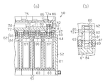
- (A) is sectional drawing which shows the battery module of FIG. 6,
- (b) is sectional drawing which expands and shows a part of FIG. 7 (a).
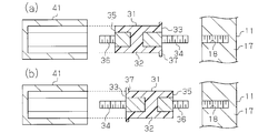
- (A) is sectional drawing which fractures
- (b) is sectional drawing which expands and shows the fastening member of Fig.8 (a).
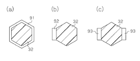
- (A), (b) and (c) is sectional drawing which shows the fastening member of a modification.
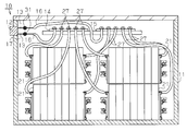
- the battery pack 10 has a housing 11.
- a plurality of battery modules 21 are accommodated in the housing 11.
- the housing 11 is provided with a connector 12 to which an external connection device (for example, a charger or a load) is connected.
- a plurality (two in this embodiment) of output harnesses 13 are connected to the connector 12.
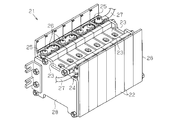
- each battery module 21 includes a plurality of battery holders 22 and a plurality of battery cells 23.
- Each battery cell 23 is held by a corresponding battery holder 22 and has a positive electrode terminal 24 and a negative electrode terminal 25.
- the battery cells 23 are arranged in a line, and the battery module 21 includes end plates 28 that restrain the battery cells 23 at both ends in the arrangement direction of the battery cells 23.
- the positive electrode terminal 24 of one battery cell 23 and the negative electrode terminal 25 of the other battery cell 23 are arranged adjacent to each other, and the adjacent positive electrode terminal 24 and negative electrode terminal are arranged. 25 are connected by a bus bar 26, whereby the battery cells 23 are connected in series.
- a connection harness 27 is connected to each battery cell 23 arranged at both ends in the arrangement direction.
- a first terminal block 14 and a second terminal block 15 are provided inside the housing 11.
- Two connection harnesses 27 extending from each battery module 21 are connected to the first terminal block 14 and the second terminal block 15, respectively.
- a connection harness 27 having the same polarity is connected to each of the terminal blocks 14 and 15, whereby a plurality of battery modules 21 are connected in parallel.
- a harness 16 that is electrically connected to the output harness 13 is connected to each of the terminal blocks 14 and 15.
- Each harness 16 is electrically connected to the output harness 13 by being fixed in a state of being in contact with the output harness 13 by a fastening member 31 provided inside the housing 11.
- the harness 16 is electrically connected to the battery cell 23 via the terminal blocks 14 and 15 and the connection harness 27.
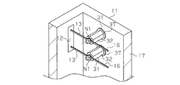
- the fastening member 31 has a column member 32 having a hexagonal column shape. As shown in FIG. 4, the column member 32 has a first end 33 and a second end 35 in the axial direction. The first end 33 is provided with a first screw 34. A second screw 36 is provided at the second end portion 35.
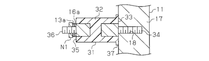
- the column member 32 is made of resin, and the first screw 34 and the second screw 36 are made of metal.
- the first screw 34 is insulated from the second screw 36 by the column member 32.
- the axial length of the first screw 34 is longer than the axial length of the second screw 36.
- An annular projecting portion 37 projecting in a direction intersecting with the axial direction of the fastening member 31 (specifically, a radial direction of the fastening member 31) is provided on the first end 33 of the fastening member 31 on the entire circumference of the column member 32. It is provided over.
- the first screw 34 is configured to be fastened to the first body to be fastened, that is, the wall portion 17 of the housing 11, and the first screw 34 is fastened to the wall portion 17. Then, the second screw 36 protrudes into the housing 11.
- the wall portion 17 of the housing 11 has a screw hole 18, and a female screw is formed on the inner peripheral surface of the screw hole 18.
- the first screw 34 is fastened to the wall portion 17 by screwing the first screw 34 into the screwing hole 18.
- a U-shaped connection fitting 16 a is provided at the end of the harness 16, and a U-shaped connection fitting 13 a is provided at the end of the output harness 13.
- connection fitting 16a of the harness 16 and the connection fitting 13a of the output harness 13 are arranged so as to overlap each other.
- the 2nd to-be-fastened body, ie, nut N1 is fastened by the 2nd screw 36, and both connection metal fittings 13a and 16a are pressed by the nut N1 toward the column member 32, and the output harness 13 and harness 16 It is fixed to the fastening member 31 in an electrically connected state.
- the axial length of the first screw 34 is substantially the same as the depth of the screwing hole 18, and the relationship between the axial length of the first screw 34 and the depth of the screwing hole 18 is fastened by at least vibration or the like. It is determined so that the member 31 does not tilt. If the axial length of the first screw 34 is too long or too short with respect to the depth of the screwing hole 18, the fastening member 31 is easily tilted by vibration. The axial length of the first screw 34 may be longer than the depth of the screw hole 18 as long as the fastening member 31 does not tilt due to vibration or the like.
- the axial length of the second screw 36 is formed to be a length obtained by combining at least the thickness of the connection fitting 13a, the thickness of the connection fitting 16a, and half the axial length of the through hole of the nut N1. ing. If the axial length of the second screw 36 is too long, the projecting length of the second screw 36 becomes long, and there is a risk of hindering the arrangement of the items accommodated in the housing 11. If the axial length of the second screw 36 is shorter than the total length of the thickness of the connection fitting 13a, the thickness of the connection fitting 16a, and half the axial length of the through hole of the nut N1, the nut N1 may come off from the first screw 36.
- the axial length of the second screw 36 is obtained by combining the thickness of the connection fitting 13a, the thickness of the connection fitting 16a, and half the axial length of the through hole of the nut N1 unless the nut N1 is removed. It may be shorter than the length.
- the lengths of the first screw 34 and the second screw 36 are determined so as to satisfy the above conditions, and have different lengths.
- FIG. 5A when the housing 11 and the nut N ⁇ b> 1 are fastened to the fastening member 31, first, the first screw 34 is fastened to the wall portion 17 of the housing 11.
- the jig 41 When the first screw 34 is fastened to the wall portion 17, the jig 41 is fitted into the column member 32 in the axial direction from the second end portion 35, and the jig 41 is rotated. As the jig 41 rotates, the first screw 34 rotates together with the column member 32, so that the first screw 34 is screwed into the screwing hole 18 of the wall portion 17.
- the jig 41 has a hexagonal cylindrical shape. On the inner surface of the jig 41, the diagonal dimension of the hexagon is slightly larger than the diagonal dimension of the hexagonal columnar column member 32 and smaller than the outer diameter of the annular projecting portion 37.
- action of the fastening member 31 of this embodiment is demonstrated.
- the first screw 34 is fastened to the wall portion 17 of the housing 11 using the jig 41.
- the nut N1 is fastened to the second screw 36 to fasten the connection fitting 16 a of the harness 16 and the connection fitting 13 a of the output harness 13. Secure to member 31.
- the following effects can be obtained. (1) Since the overhanging portion 37 restricts the jig 41 from being fitted into the column member 32 from the first end portion 33, the second screw 36 may be fastened to the wall portion 17 of the housing 11. Deterred. Therefore, the nut N1 is erroneously fastened to the first screw 34 and the second screw 36 is prevented from being fastened to the wall portion 17 of the housing 11 by mistake.
- the battery module 50 includes a plurality of battery holders 51 and a plurality of battery cells 61.
- Each battery cell 61 is held by a corresponding battery holder 22 and has a positive terminal 66 and a negative terminal 67.
- the battery cells 61 are arranged in a line, and the battery module 50 includes end plates 52 at both ends in the arrangement direction of the battery cells 61.
- the battery cell 61 includes a battery case 62 and an electrode assembly 63 accommodated in the battery case 62.
- the battery case 62 includes a cylindrical case body 64 having a bottom wall and an opening, and a flat lid 65 that closes the opening of the case body 64.
- a positive electrode terminal 66 and a negative electrode terminal 67 protrude from the lid 65.
- the positive electrode terminal 66 and the negative electrode terminal 67 each have a shaft portion 68 exposed outside the battery case 62.
- the positive electrode terminal 66 and the negative electrode terminal 67 each have a screw hole 69 extending in the axial direction at the end of the shaft portion 68 exposed from the battery case 62.
- a female screw is formed on the inner peripheral surface of each screw hole 69.
- the positive electrode terminal 66 of one battery cell 61 and the negative electrode terminal 67 of the other battery cell 61 are arranged adjacent to each other, and the adjacent positive electrode terminal 66 and negative electrode terminal are arranged. 67 are connected by a bus bar 70, whereby the battery cells 61 are connected in series.
- the row of battery holders 51 holds a mounting plate 72 on which electronic components and the like are mounted.
- the mounting plate 72 extends in the arrangement direction of the battery cells 61.
- a relay 74 for controlling the discharge of the battery cell 61 and the interruption of the discharge is provided on the mounting plate 72.
- the relay 74 is covered with a rectangular box-shaped relay cover 75.
- a plate-like bus bar 71 connected to the relay 74 is provided in the relay cover 75.
- a battery ECU 77 that controls the battery cell 61 is provided on the mounting plate 72.
- the battery ECU 77 is covered with a rectangular box-shaped ECU cover 78.
- the mounting plate 72 is provided with a through hole 72 a, and one of the two battery cells 61 arranged at both ends in the arrangement direction is one battery cell 61. Is electrically connected to the plate-like bus bar 71 by a fastening member 81 inserted through the through hole 72a.
- the fastening member 81 of the present embodiment includes a hexagonal columnar column member 82 having a first end portion 83 and a second end portion 85 in the axial direction, a first screw 84 provided at the first end portion 83, And a second screw 86 provided at the two end portions 85.
- the column member 82, the first screw 84, and the second screw 86 are all made of metal.
- the axial length of the first screw 84 is longer than the axial length of the second screw 86.
- An annular projecting portion 87 projecting in the radial direction along the end surface of the first end portion 83 is provided at the first end portion 83 of the column member 82.
- the first screw 84 is fastened (screwed) to the screwed hole 69 of the negative terminal 67 of the first object to be fastened, that is, the battery cell 61.
- a second body to be fastened that is, a nut N ⁇ b> 2 is fastened (screwed) to a portion of the second screw 86 protruding from the plate-like bus bar 71.
- the axial length of the first screw 84 is substantially the same as the depth of the screwing hole 69 of the negative electrode terminal 67, and the axial length of the first screw 84 and the depth of the screwing hole 69 are at least vibration or the like. Therefore, the fastening member 81 is determined not to tilt. If the length of the first screw 84 in the axial direction is too long or too short with respect to the depth of the screwing hole 69, the fastening member 81 is easily inclined by vibration. When the axial length of the first screw 84 is too short, the contact area between the first screw 84 and the negative electrode terminal 67 is small, and the resistance value at the contact portion is large.
- the length of the first screw 84 in the axial direction is greater than the depth of the screw hole 69 if the fastening member 81 is not inclined due to vibration or the like and a sufficient contact area between the first screw 84 and the negative electrode terminal 67 can be secured. May be longer or shorter.
- the axial length of the second screw 86 is too long, the height of the relay cover 75 (the length of the side surface of the relay cover 75 extending in parallel to the axial direction of the fastening member 81) increases, and as a result, The dimension of the whole battery module 50 will become large. If the axial length of the second screw 86 is shorter than the combined length of the thickness of the plate-like bus bar 71 and the half of the depth of the through hole of the nut N2, the nut N2 may come off. Therefore, the axial length of the second screw 86 is formed to be a length obtained by combining at least the thickness of the plate-like bus bar 71 and half the depth of the through hole of the nut N2. The axial length of the second screw 86 may be shorter than the combined length of the thickness of the plate-like bus bar 71 and half the depth of the through hole of the nut N2 if the nut N2 is not removed.
- the fastening member 81 of this embodiment will be described.
- the first screw 84 is fastened to the screwing hole 69 of the negative terminal 67 using the same jig 41 as in the first embodiment
- the nut N2 is fastened to the second screw 86.
- the protruding portion 87 restricts the jig 41 from being fitted from the first end portion 83 of the column member 82.
- the protruding portion 87 restricts the fitting of the jig 41 from the first end portion 83, the nut N2 is fastened to the first screw 84, and the second screw 86 is connected to the negative terminal 67. It is deterred from being fastened.
- the battery cell 61 can be electrically connected to the plate-like bus bar 71 by the fastening member 81.
- the shape of the overhanging portion does not have to be annular.
- a projecting portion 91 having a polygonal ring shape such as a hexagonal ring or a projecting portion 92 projecting from a part of the outer periphery of the column members 32 and 82 as shown in FIG. 9 (b). May be.
- projection part 93 which protrudes from several places as a part of outer periphery of the column members 32 and 82 may be sufficient.
- the column members 32 and 82 may have other polygonal shapes such as a pentagonal column shape.
- the overhang portions 37 and 87 may be provided at positions slightly closer to the second end portions 35 and 85 from the first end portions 33 and 83 of the column members 32 and 82.
- the jig 41 may slightly fit into the column members 32 and 82 from the first end portions 33 and 83, but when the jig 41 is rotated, the column members 32 and 82 become the second screws 36.
- , 86 need only be provided with protruding portions 37, 87 at positions where they do not rotate together.
- the overhang portions 37 and 87 only need to restrict the jig 41 from being fitted to the position where the column members 32 and 82 can be rotated from the first end portions 33 and 83. It can be said that the overhang portions 37 and 87 function as a restriction portion that restricts the fastening operation of the jig 41 with respect to the first end portions 33 and 83 of the column members 32 and 82.
- the axial lengths of the first screws 34 and 84 may be shorter than the axial lengths of the second screws 36 and 86.
- the fastening member 81 may be fastened to the positive terminal 66.
Abstract
A fastening member is provided with a column member, a first screw, and a second screw. The column member has a first end and a second end in the axial direction. The first screw is provided at the first end and is configured so as to be fastened to a first body to be fastened. The second screw is provided at the second end and is configured so as to be fastened to a second body to be fastened. The column member is configured so that a jig is axially fitted thereover from the second end, and so that rotating the jig having been fitted over the column member engages the first screw with the first body to be fastened. The first screw and the second screw have different axial lengths. The column member has a protrusion which prevents the jig from being fitted from the first end over the column member up to a position at which the jig can rotate the column member.
Description
本発明は、柱部材の軸方向両端に被締結体が締結されるように構成された締結部材に関する。
This invention relates to the fastening member comprised so that to-be-fastened body might be fastened by the axial direction both ends of a pillar member.
特許文献1には、柱部材(圧着部品)の軸方向両端に2種類の被締結体(バスバー)がそれぞれ締結されるように構成された締結部材が開示されている。
Patent Document 1 discloses a fastening member configured such that two types of fastened bodies (bus bars) are fastened to both ends in the axial direction of a column member (crimp part).
特許文献1の締結部材では、柱部材の軸方向の第1端部及び第2端部に設けられたネジに、互いに種類の異なる被締結体をそれぞれ締結している。そのため、被締結体の種類に合わせて2つのネジの長さを異ならせる場合、柱部材の第1端部に、第2端部に締結されるように準備された被締結体が誤って締結されると、ネジの長さが不足したり、ネジの長さが過多となったりする。
In the fastening member of Patent Document 1, different types of fastened bodies are fastened to screws provided at the first end and the second end in the axial direction of the column member. Therefore, when different lengths of the two screws are used according to the type of the body to be fastened, the body to be fastened prepared to be fastened to the second end is fastened to the first end of the column member by mistake. If it is done, the length of the screw is insufficient, or the length of the screw is excessive.
本発明の目的は、誤った被締結体が締結されることを抑止することができる締結部材を提供することにある。
An object of the present invention is to provide a fastening member that can prevent an erroneous fastened body from being fastened.
上記課題を解決する締結部材は、軸方向において第1端部及び第2端部を有する柱部材と、前記第1端部に設けられているとともに第1の被締結体に締結されるように構成された第1のネジと、前記第2端部に設けられているとともに第2の被締結体に締結されるように構成された第2のネジと、を備え、前記柱部材は前記第2端部から軸方向に治具が嵌め込まれるように構成され、前記柱部材に嵌め込まれた前記治具を回転させることで前記第1のネジが前記第1の被締結体に螺合され、前記第1のネジと前記第2のネジとは互いに異なる軸方向長さを有し、前記柱部材は、前記治具が前記第1端部から前記柱部材を回転させることができる位置まで前記柱部材に嵌め込まれることを規制する張り出し部を有する。
The fastening member that solves the above problem is provided with a column member having a first end and a second end in the axial direction, and is fastened to the first body to be fastened while being provided at the first end. A first screw configured, and a second screw provided at the second end and configured to be fastened to a second fastened body, wherein the column member is the first screw A jig is fitted in the axial direction from two ends, and the first screw is screwed to the first body to be fastened by rotating the jig fitted in the column member, The first screw and the second screw have different axial lengths, and the column member is moved to a position where the jig can rotate the column member from the first end. It has an overhang part which controls fitting to a pillar member.
(第1の実施形態)
以下、第1の実施形態の締結部材31について説明する。
図1に示すように、電池パック10は、筐体11を有している。筐体11には複数の電池モジュール21が収容されている。筐体11には、外部接続機器(例えば、充電器や負荷など)が接続されるコネクタ12が設けられている。コネクタ12には、複数(本実施形態では2本)の出力用ハーネス13が接続されている。 (First embodiment)
Hereinafter, the fasteningmember 31 of the first embodiment will be described.
As shown in FIG. 1, thebattery pack 10 has a housing 11. A plurality of battery modules 21 are accommodated in the housing 11. The housing 11 is provided with a connector 12 to which an external connection device (for example, a charger or a load) is connected. A plurality (two in this embodiment) of output harnesses 13 are connected to the connector 12.
以下、第1の実施形態の締結部材31について説明する。
図1に示すように、電池パック10は、筐体11を有している。筐体11には複数の電池モジュール21が収容されている。筐体11には、外部接続機器(例えば、充電器や負荷など)が接続されるコネクタ12が設けられている。コネクタ12には、複数(本実施形態では2本)の出力用ハーネス13が接続されている。 (First embodiment)
Hereinafter, the fastening
As shown in FIG. 1, the
図2に示すように、各電池モジュール21は、複数の電池ホルダ22と複数の電池セル23とを備えている。各電池セル23は、対応する電池ホルダ22に保持され、正極端子24と負極端子25とを有している。電池セル23は一列に配列され、電池モジュール21は、電池セル23の配列方向の両端に電池セル23を拘束するエンドプレート28を備えている。配列方向に隣り合う2つの電池セル23について、一方の電池セル23の正極端子24と他方の電池セル23の負極端子25とが隣り合うように配置されるとともに、隣り合う正極端子24と負極端子25とがバスバー26によって接続され、それによって電池セル23が直列接続されている。配列方向の両端に配置された電池セル23には、それぞれ接続用ハーネス27が接続されている。
As shown in FIG. 2, each battery module 21 includes a plurality of battery holders 22 and a plurality of battery cells 23. Each battery cell 23 is held by a corresponding battery holder 22 and has a positive electrode terminal 24 and a negative electrode terminal 25. The battery cells 23 are arranged in a line, and the battery module 21 includes end plates 28 that restrain the battery cells 23 at both ends in the arrangement direction of the battery cells 23. For two battery cells 23 adjacent in the arrangement direction, the positive electrode terminal 24 of one battery cell 23 and the negative electrode terminal 25 of the other battery cell 23 are arranged adjacent to each other, and the adjacent positive electrode terminal 24 and negative electrode terminal are arranged. 25 are connected by a bus bar 26, whereby the battery cells 23 are connected in series. A connection harness 27 is connected to each battery cell 23 arranged at both ends in the arrangement direction.
図1に示すように、筐体11の内部には、第1の端子台14及び第2の端子台15が設けられている。各電池モジュール21から延びる2本の接続用ハーネス27は、それぞれ第1の端子台14及び第2の端子台15に接続されている。各端子台14,15には、同一極性の接続用ハーネス27が接続され、これにより複数の電池モジュール21が並列接続されている。
As shown in FIG. 1, a first terminal block 14 and a second terminal block 15 are provided inside the housing 11. Two connection harnesses 27 extending from each battery module 21 are connected to the first terminal block 14 and the second terminal block 15, respectively. A connection harness 27 having the same polarity is connected to each of the terminal blocks 14 and 15, whereby a plurality of battery modules 21 are connected in parallel.
各端子台14,15には、出力用ハーネス13と電気的に接続されるハーネス16が接続されている。各ハーネス16は、筐体11の内部に設けられた締結部材31によって出力用ハーネス13と当接した状態で固定されることで、出力用ハーネス13と電気的に接続されている。ハーネス16は、各端子台14,15及び各接続用ハーネス27を介して電池セル23と電気的に接続されている。
A harness 16 that is electrically connected to the output harness 13 is connected to each of the terminal blocks 14 and 15. Each harness 16 is electrically connected to the output harness 13 by being fixed in a state of being in contact with the output harness 13 by a fastening member 31 provided inside the housing 11. The harness 16 is electrically connected to the battery cell 23 via the terminal blocks 14 and 15 and the connection harness 27.
図3に示すように、複数(本実施形態では2個)の締結部材31は、筐体11の壁部17に設けられている。締結部材31は、六角柱状をなす柱部材32を有している。図4に示すように、柱部材32は軸方向において第1端部33と第2端部35とを有している。第1端部33には、第1のネジ34が設けられている。第2端部35には、第2のネジ36が設けられている。柱部材32は樹脂製であり、第1のネジ34及び第2のネジ36は金属製である。柱部材32によって、第1のネジ34が第2のネジ36から絶縁されている。第1のネジ34の軸方向長さは、第2のネジ36の軸方向長さよりも長い。締結部材31の第1端部33には、締結部材31の軸方向と交わる方向(具体的には締結部材31の径方向)に張り出す円環状の張り出し部37が柱部材32の全周に亘って設けられている。
As shown in FIG. 3, a plurality of (two in this embodiment) fastening members 31 are provided on the wall portion 17 of the housing 11. The fastening member 31 has a column member 32 having a hexagonal column shape. As shown in FIG. 4, the column member 32 has a first end 33 and a second end 35 in the axial direction. The first end 33 is provided with a first screw 34. A second screw 36 is provided at the second end portion 35. The column member 32 is made of resin, and the first screw 34 and the second screw 36 are made of metal. The first screw 34 is insulated from the second screw 36 by the column member 32. The axial length of the first screw 34 is longer than the axial length of the second screw 36. An annular projecting portion 37 projecting in a direction intersecting with the axial direction of the fastening member 31 (specifically, a radial direction of the fastening member 31) is provided on the first end 33 of the fastening member 31 on the entire circumference of the column member 32. It is provided over.
図4に示すように、第1のネジ34は第1の被締結体すなわち筐体11の壁部17に締結されるように構成され、第1のネジ34が壁部17に締結された状態では、第2のネジ36が筐体11の内部に突出している。筐体11の壁部17は螺合穴18を有し、螺合穴18の内周面には雌ねじが形成されている。螺合穴18に第1のネジ34が螺合されることにより、壁部17に第1のネジ34が締結されている。ハーネス16の端部にはU字状の接続金具16aが設けられ、出力用ハーネス13の端部にはU字状の接続金具13aが設けられている。第2のネジ36の周囲には、ハーネス16の接続金具16aと出力用ハーネス13の接続金具13aとが重ね合わされた状態で配置されている。そして、第2のネジ36に第2の被締結体すなわちナットN1が締結され、両接続金具13a,16aが柱部材32に向けてナットN1により押しつけられることで、出力用ハーネス13がハーネス16と電気的に接続された状態で締結部材31に固定されている。
As shown in FIG. 4, the first screw 34 is configured to be fastened to the first body to be fastened, that is, the wall portion 17 of the housing 11, and the first screw 34 is fastened to the wall portion 17. Then, the second screw 36 protrudes into the housing 11. The wall portion 17 of the housing 11 has a screw hole 18, and a female screw is formed on the inner peripheral surface of the screw hole 18. The first screw 34 is fastened to the wall portion 17 by screwing the first screw 34 into the screwing hole 18. A U-shaped connection fitting 16 a is provided at the end of the harness 16, and a U-shaped connection fitting 13 a is provided at the end of the output harness 13. Around the second screw 36, the connection fitting 16a of the harness 16 and the connection fitting 13a of the output harness 13 are arranged so as to overlap each other. And the 2nd to-be-fastened body, ie, nut N1, is fastened by the 2nd screw 36, and both connection metal fittings 13a and 16a are pressed by the nut N1 toward the column member 32, and the output harness 13 and harness 16 It is fixed to the fastening member 31 in an electrically connected state.
第1のネジ34の軸方向長さは螺合穴18の深さと略同じであり、第1のネジ34の軸方向長さ及び螺合穴18の深さの関係は、少なくとも振動等により締結部材31が傾かないように定められている。第1のネジ34の軸方向長さが螺合穴18の深さに対して長すぎたり短すぎたりすると、締結部材31が振動によって傾きやすくなる。第1のネジ34の軸方向長さは、振動等により締結部材31が傾かなければ、螺合穴18の深さよりも長くてもよい。
The axial length of the first screw 34 is substantially the same as the depth of the screwing hole 18, and the relationship between the axial length of the first screw 34 and the depth of the screwing hole 18 is fastened by at least vibration or the like. It is determined so that the member 31 does not tilt. If the axial length of the first screw 34 is too long or too short with respect to the depth of the screwing hole 18, the fastening member 31 is easily tilted by vibration. The axial length of the first screw 34 may be longer than the depth of the screw hole 18 as long as the fastening member 31 does not tilt due to vibration or the like.
第2のネジ36の軸方向長さは、少なくとも、接続金具13aの厚さと、接続金具16aの厚さと、ナットN1の貫通孔の軸方向長さの半分と、を合わせた長さに形成されている。第2のネジ36の軸方向長さが長過ぎると、第2のネジ36の突出長が長くなり、筐体11に収容される収容物の配設を阻害するおそれがある。また、第2のネジ36の軸方向長さが接続金具13aの厚さと、接続金具16aの厚さと、ナットN1の貫通孔の軸方向長さの半分と、を合わせた長さより短いと、ナットN1が第1のネジ36から外れてしまうおそれがある。第2のネジ36の軸方向長さは、ナットN1が外れなければ、接続金具13aの厚さと、接続金具16aの厚さと、ナットN1の貫通孔の軸方向長さの半分と、を合わせた長さより短くてもよい。
The axial length of the second screw 36 is formed to be a length obtained by combining at least the thickness of the connection fitting 13a, the thickness of the connection fitting 16a, and half the axial length of the through hole of the nut N1. ing. If the axial length of the second screw 36 is too long, the projecting length of the second screw 36 becomes long, and there is a risk of hindering the arrangement of the items accommodated in the housing 11. If the axial length of the second screw 36 is shorter than the total length of the thickness of the connection fitting 13a, the thickness of the connection fitting 16a, and half the axial length of the through hole of the nut N1, the nut N1 may come off from the first screw 36. The axial length of the second screw 36 is obtained by combining the thickness of the connection fitting 13a, the thickness of the connection fitting 16a, and half the axial length of the through hole of the nut N1 unless the nut N1 is removed. It may be shorter than the length.
以上のように、第1のネジ34と、第2のネジ36とは、上記条件を満たすように長さがそれぞれ定められており、互いに異なる長さを有している。
図5(a)に示すように、締結部材31に筐体11及びナットN1を締結するときには、まず第1のネジ34を筐体11の壁部17に締結する。第1のネジ34を壁部17に締結するときには、治具41を第2端部35から軸方向に柱部材32に嵌め込み、治具41を回転させる。治具41の回転に伴い、第1のネジ34が柱部材32と一体となって回転することで、第1のネジ34は壁部17の螺合穴18に螺入されていく。治具41は、六角筒状をなしている。治具41の内面において、六角形の対角の寸法は、六角柱状の柱部材32の対角の寸法よりも若干大きく、円環状の張り出し部37の外径よりも小さい。 As described above, the lengths of thefirst screw 34 and the second screw 36 are determined so as to satisfy the above conditions, and have different lengths.
As shown in FIG. 5A, when thehousing 11 and the nut N <b> 1 are fastened to the fastening member 31, first, the first screw 34 is fastened to the wall portion 17 of the housing 11. When the first screw 34 is fastened to the wall portion 17, the jig 41 is fitted into the column member 32 in the axial direction from the second end portion 35, and the jig 41 is rotated. As the jig 41 rotates, the first screw 34 rotates together with the column member 32, so that the first screw 34 is screwed into the screwing hole 18 of the wall portion 17. The jig 41 has a hexagonal cylindrical shape. On the inner surface of the jig 41, the diagonal dimension of the hexagon is slightly larger than the diagonal dimension of the hexagonal columnar column member 32 and smaller than the outer diameter of the annular projecting portion 37.
図5(a)に示すように、締結部材31に筐体11及びナットN1を締結するときには、まず第1のネジ34を筐体11の壁部17に締結する。第1のネジ34を壁部17に締結するときには、治具41を第2端部35から軸方向に柱部材32に嵌め込み、治具41を回転させる。治具41の回転に伴い、第1のネジ34が柱部材32と一体となって回転することで、第1のネジ34は壁部17の螺合穴18に螺入されていく。治具41は、六角筒状をなしている。治具41の内面において、六角形の対角の寸法は、六角柱状の柱部材32の対角の寸法よりも若干大きく、円環状の張り出し部37の外径よりも小さい。 As described above, the lengths of the
As shown in FIG. 5A, when the
次に、本実施形態の締結部材31の作用について説明する。
図4及び図5(a)に示すようにまず、治具41を用いて第1のネジ34を筺体11の壁部17に締結する。第1のネジ34が筐体11の壁部17に締結された後に、第2のネジ36にナットN1を締結して、ハーネス16の接続金具16aと出力用ハーネス13の接続金具13aとを締結部材31に固定する。 Next, the effect | action of thefastening member 31 of this embodiment is demonstrated.
As shown in FIGS. 4 and 5A, first, thefirst screw 34 is fastened to the wall portion 17 of the housing 11 using the jig 41. After the first screw 34 is fastened to the wall portion 17 of the housing 11, the nut N1 is fastened to the second screw 36 to fasten the connection fitting 16 a of the harness 16 and the connection fitting 13 a of the output harness 13. Secure to member 31.
図4及び図5(a)に示すようにまず、治具41を用いて第1のネジ34を筺体11の壁部17に締結する。第1のネジ34が筐体11の壁部17に締結された後に、第2のネジ36にナットN1を締結して、ハーネス16の接続金具16aと出力用ハーネス13の接続金具13aとを締結部材31に固定する。 Next, the effect | action of the
As shown in FIGS. 4 and 5A, first, the
図5(b)に示すように、締結部材31を筐体11に固定するときに、治具41を第1端部33から柱部材32に嵌め込もうとすると、張り出し部37によって治具41が柱部材32に嵌め込まれることが規制される。したがって、筐体11の壁部17に治具41を用いて締結部材31を取り付ける場合、第1のネジ34が壁部17に締結されることのみが許容される。
As shown in FIG. 5 (b), when the fastening member 31 is fixed to the housing 11, if the jig 41 is to be fitted into the pillar member 32 from the first end portion 33, the overhanging portion 37 causes the jig 41 to be fitted. Is restricted from being fitted into the column member 32. Therefore, when the fastening member 31 is attached to the wall portion 17 of the housing 11 using the jig 41, only the first screw 34 is allowed to be fastened to the wall portion 17.
したがって、上記実施形態によれば、以下の効果を得ることができる。
(1)張り出し部37によって、治具41が第1端部33から柱部材32に嵌め込まれることが規制されるため、第2のネジ36が筐体11の壁部17に締結されることが抑止される。したがって、第1のネジ34に誤ってナットN1が締結されること、並びに、第2のネジ36が誤って筐体11の壁部17に締結されることが抑止される。 Therefore, according to the above embodiment, the following effects can be obtained.
(1) Since the overhangingportion 37 restricts the jig 41 from being fitted into the column member 32 from the first end portion 33, the second screw 36 may be fastened to the wall portion 17 of the housing 11. Deterred. Therefore, the nut N1 is erroneously fastened to the first screw 34 and the second screw 36 is prevented from being fastened to the wall portion 17 of the housing 11 by mistake.
(1)張り出し部37によって、治具41が第1端部33から柱部材32に嵌め込まれることが規制されるため、第2のネジ36が筐体11の壁部17に締結されることが抑止される。したがって、第1のネジ34に誤ってナットN1が締結されること、並びに、第2のネジ36が誤って筐体11の壁部17に締結されることが抑止される。 Therefore, according to the above embodiment, the following effects can be obtained.
(1) Since the overhanging
(2)柱部材32は、樹脂製であるため、第1のネジ34が第2のネジ36から電気的に絶縁されている。したがって、電池セル23の短絡が抑止されている。
(第2の実施形態)
以下、第2の実施形態の締結部材81について説明する。 (2) Since thecolumn member 32 is made of resin, the first screw 34 is electrically insulated from the second screw 36. Therefore, the short circuit of the battery cell 23 is suppressed.
(Second Embodiment)
Hereinafter, thefastening member 81 of the second embodiment will be described.
(第2の実施形態)
以下、第2の実施形態の締結部材81について説明する。 (2) Since the
(Second Embodiment)
Hereinafter, the
図6、図7(a)、及び図7(b)に示すように、電池モジュール50は、複数の電池ホルダ51と複数の電池セル61とを備えている。各電池セル61は、対応する電池ホルダ22に保持され、正極端子66と負極端子67とを有している。電池セル61は一列に配列され、電池モジュール50は、電池セル61の配列方向の両端にエンドプレート52を備えている。
As shown in FIGS. 6, 7 (a), and 7 (b), the battery module 50 includes a plurality of battery holders 51 and a plurality of battery cells 61. Each battery cell 61 is held by a corresponding battery holder 22 and has a positive terminal 66 and a negative terminal 67. The battery cells 61 are arranged in a line, and the battery module 50 includes end plates 52 at both ends in the arrangement direction of the battery cells 61.
電池セル61は、電池ケース62と、電池ケース62に収容される電極組立体63とを備えている。電池ケース62は、底壁及び開口を有する筒状のケース本体64と、ケース本体64の開口を閉塞する平板状の蓋65とを有している。蓋65から正極端子66及び負極端子67が突出している。正極端子66及び負極端子67は、電池ケース62外に露出する軸部68をそれぞれ有している。また、正極端子66及び負極端子67は、電池ケース62から露出する軸部68の端部に軸方向に延びる螺合穴69をそれぞれ有している。各螺合穴69の内周面に雌ねじが形成されている。
The battery cell 61 includes a battery case 62 and an electrode assembly 63 accommodated in the battery case 62. The battery case 62 includes a cylindrical case body 64 having a bottom wall and an opening, and a flat lid 65 that closes the opening of the case body 64. A positive electrode terminal 66 and a negative electrode terminal 67 protrude from the lid 65. The positive electrode terminal 66 and the negative electrode terminal 67 each have a shaft portion 68 exposed outside the battery case 62. The positive electrode terminal 66 and the negative electrode terminal 67 each have a screw hole 69 extending in the axial direction at the end of the shaft portion 68 exposed from the battery case 62. A female screw is formed on the inner peripheral surface of each screw hole 69.
配列方向に隣り合う2つの電池セル61について、一方の電池セル61の正極端子66と他方の電池セル61の負極端子67とが隣り合うように配置されるとともに、隣り合う正極端子66と負極端子67とがバスバー70によって接続され、それによって電池セル61が直列接続されている。
For two battery cells 61 adjacent in the arrangement direction, the positive electrode terminal 66 of one battery cell 61 and the negative electrode terminal 67 of the other battery cell 61 are arranged adjacent to each other, and the adjacent positive electrode terminal 66 and negative electrode terminal are arranged. 67 are connected by a bus bar 70, whereby the battery cells 61 are connected in series.
電池ホルダ51の列は、電子部品などが載置される載置板72を保持している。載置板72は、電池セル61の配列方向に延びている。載置板72上には、電池セル61の放電及び放電の遮断を制御するリレー74が設けられている。リレー74は、矩形箱形のリレー用カバー75によって覆われている。リレー用カバー75内には、リレー74と接続される板状バスバー71が設けられている。載置板72上には、電池セル61の制御を行う電池ECU77が設けられている。電池ECU77は、矩形箱形のECU用カバー78によって覆われている。
The row of battery holders 51 holds a mounting plate 72 on which electronic components and the like are mounted. The mounting plate 72 extends in the arrangement direction of the battery cells 61. On the mounting plate 72, a relay 74 for controlling the discharge of the battery cell 61 and the interruption of the discharge is provided. The relay 74 is covered with a rectangular box-shaped relay cover 75. A plate-like bus bar 71 connected to the relay 74 is provided in the relay cover 75. A battery ECU 77 that controls the battery cell 61 is provided on the mounting plate 72. The battery ECU 77 is covered with a rectangular box-shaped ECU cover 78.
図8(a)及び図8(b)に示すように、載置板72には貫通孔72aが設けられ、配列方向の両端に配置された2つの電池セル61のうち、一方の電池セル61は、貫通孔72aに挿通された締結部材81によって、板状バスバー71と電気的に接続されている。本実施形態の締結部材81は、軸方向において第1端部83及び第2端部85を有する六角柱状の柱部材82と、第1端部83に設けられた第1のネジ84と、第2端部85に設けられた第2のネジ86とを有している。柱部材82、第1のネジ84、及び第2のネジ86は、全て金属製である。第1のネジ84の軸方向長さは、第2のネジ86の軸方向長さよりも長い。柱部材82の第1端部83には、第1端部83の端面に沿って径方向に張り出す円環状の張り出し部87が設けられている。
As shown in FIGS. 8A and 8B, the mounting plate 72 is provided with a through hole 72 a, and one of the two battery cells 61 arranged at both ends in the arrangement direction is one battery cell 61. Is electrically connected to the plate-like bus bar 71 by a fastening member 81 inserted through the through hole 72a. The fastening member 81 of the present embodiment includes a hexagonal columnar column member 82 having a first end portion 83 and a second end portion 85 in the axial direction, a first screw 84 provided at the first end portion 83, And a second screw 86 provided at the two end portions 85. The column member 82, the first screw 84, and the second screw 86 are all made of metal. The axial length of the first screw 84 is longer than the axial length of the second screw 86. An annular projecting portion 87 projecting in the radial direction along the end surface of the first end portion 83 is provided at the first end portion 83 of the column member 82.
第1のネジ84は、第1の被締結体すなわち電池セル61の負極端子67の螺合穴69に締結(螺合)されている。第2のネジ86において板状バスバー71から突出する部分には、第2の被締結体すなわちナットN2が締結(螺合)されている。
The first screw 84 is fastened (screwed) to the screwed hole 69 of the negative terminal 67 of the first object to be fastened, that is, the battery cell 61. A second body to be fastened, that is, a nut N <b> 2 is fastened (screwed) to a portion of the second screw 86 protruding from the plate-like bus bar 71.
第1のネジ84の軸方向長さは負極端子67の螺合穴69の深さと略同じであり、第1のネジ84の軸方向長さ及び螺合穴69の深さは、少なくとも振動等により締結部材81が傾かないように定められている。第1のネジ84の軸方向長さは、螺合穴69の深さに対して長すぎたり短すぎたりすると、締結部材81が振動によって傾きやすくなる。また、第1のネジ84の軸方向長さが短すぎる場合には、第1のネジ84と負極端子67との接触面積が小さく、その接触部分における抵抗値が大きくなる。第1のネジ84の軸方向長さは、振動等により締結部材81が傾かず、かつ、十分に第1のネジ84と負極端子67との接触面積が確保できれば、螺合穴69の深さよりも長くても短くてもよい。
The axial length of the first screw 84 is substantially the same as the depth of the screwing hole 69 of the negative electrode terminal 67, and the axial length of the first screw 84 and the depth of the screwing hole 69 are at least vibration or the like. Therefore, the fastening member 81 is determined not to tilt. If the length of the first screw 84 in the axial direction is too long or too short with respect to the depth of the screwing hole 69, the fastening member 81 is easily inclined by vibration. When the axial length of the first screw 84 is too short, the contact area between the first screw 84 and the negative electrode terminal 67 is small, and the resistance value at the contact portion is large. The length of the first screw 84 in the axial direction is greater than the depth of the screw hole 69 if the fastening member 81 is not inclined due to vibration or the like and a sufficient contact area between the first screw 84 and the negative electrode terminal 67 can be secured. May be longer or shorter.
第2のネジ86の軸方向長さが長過ぎると、リレー用カバー75の高さ(締結部材81の軸方向に平行に延びるリレー用カバー75の側面の長さ)が大きくなり、その結果、電池モジュール50全体の寸法が大きくなってしまう。第2のネジ86の軸方向長さは、板状バスバー71の厚さと、ナットN2の貫通孔の深さの半分と、を合わせた長さより短いとナットN2が外れてしまうおそれがある。そのため、第2のネジ86の軸方向長さは、少なくとも、板状バスバー71の厚さと、ナットN2の貫通孔の深さの半分と、を合わせた長さに形成されている。第2のネジ86の軸方向長さは、ナットN2が外れなければ、板状バスバー71の厚さと、ナットN2の貫通孔の深さの半分と、を合わせた長さより短くてもよい。
If the axial length of the second screw 86 is too long, the height of the relay cover 75 (the length of the side surface of the relay cover 75 extending in parallel to the axial direction of the fastening member 81) increases, and as a result, The dimension of the whole battery module 50 will become large. If the axial length of the second screw 86 is shorter than the combined length of the thickness of the plate-like bus bar 71 and the half of the depth of the through hole of the nut N2, the nut N2 may come off. Therefore, the axial length of the second screw 86 is formed to be a length obtained by combining at least the thickness of the plate-like bus bar 71 and half the depth of the through hole of the nut N2. The axial length of the second screw 86 may be shorter than the combined length of the thickness of the plate-like bus bar 71 and half the depth of the through hole of the nut N2 if the nut N2 is not removed.
次に、本実施形態の締結部材81の作用について説明する。
第1の実施形態と同一の治具41を用いて、第1のネジ84を負極端子67の螺合穴69に締結した後に、第2のネジ86にナットN2を締結する。このとき、張り出し部87によって治具41が柱部材82の第1端部83から嵌め込まれることが規制される。 Next, the operation of thefastening member 81 of this embodiment will be described.
After thefirst screw 84 is fastened to the screwing hole 69 of the negative terminal 67 using the same jig 41 as in the first embodiment, the nut N2 is fastened to the second screw 86. At this time, the protruding portion 87 restricts the jig 41 from being fitted from the first end portion 83 of the column member 82.
第1の実施形態と同一の治具41を用いて、第1のネジ84を負極端子67の螺合穴69に締結した後に、第2のネジ86にナットN2を締結する。このとき、張り出し部87によって治具41が柱部材82の第1端部83から嵌め込まれることが規制される。 Next, the operation of the
After the
したがって、本実施形態によれば、以下の効果を得ることができる。
(3)張り出し部87によって治具41が第1端部83から嵌め込まれることが規制されるため、第1のネジ84にナットN2が締結されること、並びに第2のネジ86が負極端子67に締結されることが抑止される。 Therefore, according to the present embodiment, the following effects can be obtained.
(3) Since the protrudingportion 87 restricts the fitting of the jig 41 from the first end portion 83, the nut N2 is fastened to the first screw 84, and the second screw 86 is connected to the negative terminal 67. It is deterred from being fastened.
(3)張り出し部87によって治具41が第1端部83から嵌め込まれることが規制されるため、第1のネジ84にナットN2が締結されること、並びに第2のネジ86が負極端子67に締結されることが抑止される。 Therefore, according to the present embodiment, the following effects can be obtained.
(3) Since the protruding
(4)柱部材82、第1のネジ84、及び第2のネジ86は、全て金属製であるため、締結部材81によって電池セル61を板状バスバー71と電気的に接続することができる。
(4) Since the column member 82, the first screw 84, and the second screw 86 are all made of metal, the battery cell 61 can be electrically connected to the plate-like bus bar 71 by the fastening member 81.
なお、実施形態は、以下のように変更してもよい。
・張り出し部の形状は、円環状でなくともよい。図9(a)に示すように、六角環状などの多角環状の張り出し部91や、図9(b)に示すように、柱部材32,82の外周の一部から張り出す張り出し部92であってもよい。また、図9(c)に示すように、柱部材32,82の外周の一部として複数箇所から張り出す張り出し部93であってもよい。 In addition, you may change embodiment as follows.
-The shape of the overhanging portion does not have to be annular. As shown in FIG. 9 (a), a projectingportion 91 having a polygonal ring shape such as a hexagonal ring or a projecting portion 92 projecting from a part of the outer periphery of the column members 32 and 82 as shown in FIG. 9 (b). May be. Moreover, as shown in FIG.9 (c), the overhang | projection part 93 which protrudes from several places as a part of outer periphery of the column members 32 and 82 may be sufficient.
・張り出し部の形状は、円環状でなくともよい。図9(a)に示すように、六角環状などの多角環状の張り出し部91や、図9(b)に示すように、柱部材32,82の外周の一部から張り出す張り出し部92であってもよい。また、図9(c)に示すように、柱部材32,82の外周の一部として複数箇所から張り出す張り出し部93であってもよい。 In addition, you may change embodiment as follows.
-The shape of the overhanging portion does not have to be annular. As shown in FIG. 9 (a), a projecting
・柱部材32,82は、五角柱状など、他の多角形状であってもよい。
・各実施形態において、張り出し部37,87は、柱部材32,82の第1端部33,83から若干第2端部35,85に近づけた位置に設けられていてもよい。この場合、治具41が僅かに第1端部33,83から柱部材32,82に嵌め込まれるおそれがあるが、治具41を回転させたときに柱部材32,82が第2のネジ36,86と一体となって回転しないような位置に張り出し部37,87が設けられていればよい。すなわち、張り出し部37,87は、治具41が第1端部33,83から柱部材32,82を回転させることができる位置まで嵌め込まれることを規制していればよい。張り出し部37,87は、柱部材32,82の第1端部33,83に対する治具41の締結動作を規制する規制部として機能するともいえる。 -The column members 32 and 82 may have other polygonal shapes such as a pentagonal column shape.
In each embodiment, the overhang portions 37 and 87 may be provided at positions slightly closer to the second end portions 35 and 85 from the first end portions 33 and 83 of the column members 32 and 82. In this case, the jig 41 may slightly fit into the column members 32 and 82 from the first end portions 33 and 83, but when the jig 41 is rotated, the column members 32 and 82 become the second screws 36. , 86 need only be provided with protruding portions 37, 87 at positions where they do not rotate together. That is, the overhang portions 37 and 87 only need to restrict the jig 41 from being fitted to the position where the column members 32 and 82 can be rotated from the first end portions 33 and 83. It can be said that the overhang portions 37 and 87 function as a restriction portion that restricts the fastening operation of the jig 41 with respect to the first end portions 33 and 83 of the column members 32 and 82.
・各実施形態において、張り出し部37,87は、柱部材32,82の第1端部33,83から若干第2端部35,85に近づけた位置に設けられていてもよい。この場合、治具41が僅かに第1端部33,83から柱部材32,82に嵌め込まれるおそれがあるが、治具41を回転させたときに柱部材32,82が第2のネジ36,86と一体となって回転しないような位置に張り出し部37,87が設けられていればよい。すなわち、張り出し部37,87は、治具41が第1端部33,83から柱部材32,82を回転させることができる位置まで嵌め込まれることを規制していればよい。張り出し部37,87は、柱部材32,82の第1端部33,83に対する治具41の締結動作を規制する規制部として機能するともいえる。 -The
In each embodiment, the
・各実施形態において、第1のネジ34,84の軸方向長さが第2のネジ36,86の軸方向長さよりも短くてもよい。
・第2の実施形態において締結部材81は、正極端子66に締結されてもよい。 In each embodiment, the axial lengths of the first screws 34 and 84 may be shorter than the axial lengths of the second screws 36 and 86.
In the second embodiment, thefastening member 81 may be fastened to the positive terminal 66.
・第2の実施形態において締結部材81は、正極端子66に締結されてもよい。 In each embodiment, the axial lengths of the
In the second embodiment, the
Claims (2)
- 軸方向において第1端部及び第2端部を有する柱部材と、
前記第1端部に設けられているとともに第1の被締結体に締結されるように構成された第1のネジと、
前記第2端部に設けられているとともに第2の被締結体に締結されるように構成された第2のネジと、を備え、
前記柱部材は前記第2端部から軸方向に治具が嵌め込まれるように構成され、前記柱部材に嵌め込まれた前記治具を回転させることで前記第1のネジが前記第1の被締結体に螺合され、
前記第1のネジと前記第2のネジとは互いに異なる軸方向長さを有し、
前記柱部材は、前記治具が前記第1端部から前記柱部材を回転させることができる位置まで前記柱部材に嵌め込まれることを規制する張り出し部を有する締結部材。 A pillar member having a first end and a second end in the axial direction;
A first screw provided at the first end and configured to be fastened to a first fastened body;
A second screw provided at the second end and configured to be fastened to a second fastened body,
The column member is configured such that a jig is fitted in the axial direction from the second end portion, and the first screw is fastened to the first fastening by rotating the jig fitted in the column member. Screwed into the body,
The first screw and the second screw have different axial lengths;
The said column member is a fastening member which has an overhang | projection part which controls that the said jig | tool is fitted in the said column member to the position which can rotate the said column member from the said 1st end part. - 前記柱部材は、絶縁性の樹脂であり、
前記第1の被締結体及び前記第2の被締結体のうち一方は電池セルに電気的に接続されたハーネスを固定するためのナットであり、他方は前記電池セルを収容する筐体である請求項1に記載の締結部材。 The column member is an insulating resin,
One of the first fastened body and the second fastened body is a nut for fixing a harness electrically connected to the battery cell, and the other is a housing for housing the battery cell. The fastening member according to claim 1.
Priority Applications (2)
| Application Number | Priority Date | Filing Date | Title |
|---|---|---|---|
| US15/122,762 US10319977B2 (en) | 2014-03-12 | 2015-02-23 | Fastening system with jig restriction flange |
| DE112015001164.1T DE112015001164T5 (en) | 2014-03-12 | 2015-02-23 | attachment member |
Applications Claiming Priority (2)
| Application Number | Priority Date | Filing Date | Title |
|---|---|---|---|
| JP2014048779A JP6369059B2 (en) | 2014-03-12 | 2014-03-12 | Fastening member |
| JP2014-048779 | 2014-03-12 |
Publications (1)
| Publication Number | Publication Date |
|---|---|
| WO2015137097A1 true WO2015137097A1 (en) | 2015-09-17 |
Family
ID=54071546
Family Applications (1)
| Application Number | Title | Priority Date | Filing Date |
|---|---|---|---|
| PCT/JP2015/054910 WO2015137097A1 (en) | 2014-03-12 | 2015-02-23 | Fastening member |
Country Status (4)
| Country | Link |
|---|---|
| US (1) | US10319977B2 (en) |
| JP (1) | JP6369059B2 (en) |
| DE (1) | DE112015001164T5 (en) |
| WO (1) | WO2015137097A1 (en) |
Families Citing this family (4)
| Publication number | Priority date | Publication date | Assignee | Title |
|---|---|---|---|---|
| JP6387798B2 (en) * | 2014-11-11 | 2018-09-12 | 株式会社豊田自動織機 | Support member |
| US10727460B2 (en) * | 2016-03-16 | 2020-07-28 | Kabushiki Kaisha Toshiba | Battery pack |
| JP6705340B2 (en) * | 2016-08-30 | 2020-06-03 | 株式会社豊田自動織機 | Battery pack |
| JP6790595B2 (en) * | 2016-08-30 | 2020-11-25 | 株式会社豊田自動織機 | Battery pack |
Citations (5)
| Publication number | Priority date | Publication date | Assignee | Title |
|---|---|---|---|---|
| JPS5738911U (en) * | 1980-08-13 | 1982-03-02 | ||
| JPS6389414U (en) * | 1987-07-17 | 1988-06-10 | ||
| JPH11120986A (en) * | 1997-10-13 | 1999-04-30 | Toyota Motor Corp | Battery holder connecting plate and its manufacture |
| JP2004031122A (en) * | 2002-06-26 | 2004-01-29 | Nissan Motor Co Ltd | Cell module |
| JP2006324060A (en) * | 2005-05-17 | 2006-11-30 | Honda Motor Co Ltd | Energy storage device |
Family Cites Families (7)
| Publication number | Priority date | Publication date | Assignee | Title |
|---|---|---|---|---|
| US2437344A (en) * | 1944-10-27 | 1948-03-09 | Herman M Behlmann | Insulator and support for electrically charged fence wires |
| US2444046A (en) * | 1945-06-05 | 1948-06-29 | Jacobs Frank | Coupling terminal unit for storage batteries |
| US3345452A (en) * | 1964-02-27 | 1967-10-03 | Thomas & Betts Corp | Sintered powdered metal connectors |
| JPS5948124B2 (en) | 1980-08-21 | 1984-11-24 | 工業技術院長 | Sedimentation treatment equipment |
| JPS6389414A (en) | 1986-10-03 | 1988-04-20 | Mitsubishi Metal Corp | Production of chloropolysilane |
| JPH05205791A (en) | 1992-01-30 | 1993-08-13 | Mitsubishi Electric Corp | Large current wiring board |
| US8748034B2 (en) * | 2011-04-14 | 2014-06-10 | Gs Yuasa International Ltd. | Battery including baffling member including one of projecting portion and recessed portion extending from lid plate |
-
2014
- 2014-03-12 JP JP2014048779A patent/JP6369059B2/en not_active Expired - Fee Related
-
2015
- 2015-02-23 WO PCT/JP2015/054910 patent/WO2015137097A1/en active Application Filing
- 2015-02-23 US US15/122,762 patent/US10319977B2/en not_active Expired - Fee Related
- 2015-02-23 DE DE112015001164.1T patent/DE112015001164T5/en not_active Ceased
Patent Citations (5)
| Publication number | Priority date | Publication date | Assignee | Title |
|---|---|---|---|---|
| JPS5738911U (en) * | 1980-08-13 | 1982-03-02 | ||
| JPS6389414U (en) * | 1987-07-17 | 1988-06-10 | ||
| JPH11120986A (en) * | 1997-10-13 | 1999-04-30 | Toyota Motor Corp | Battery holder connecting plate and its manufacture |
| JP2004031122A (en) * | 2002-06-26 | 2004-01-29 | Nissan Motor Co Ltd | Cell module |
| JP2006324060A (en) * | 2005-05-17 | 2006-11-30 | Honda Motor Co Ltd | Energy storage device |
Also Published As
| Publication number | Publication date |
|---|---|
| US20170069899A1 (en) | 2017-03-09 |
| US10319977B2 (en) | 2019-06-11 |
| JP2015172411A (en) | 2015-10-01 |
| JP6369059B2 (en) | 2018-08-08 |
| DE112015001164T5 (en) | 2016-11-24 |
Similar Documents
| Publication | Publication Date | Title |
|---|---|---|
| WO2015137097A1 (en) | Fastening member | |
| JP6327072B2 (en) | Battery module | |
| US10269522B2 (en) | Fuse unit | |
| JP5870445B2 (en) | Pipe fitting with earth function | |
| WO2016084760A1 (en) | Wiring module | |
| JP2008192595A (en) | Battery device | |
| WO2013084713A1 (en) | Battery wiring module | |
| US9349999B2 (en) | Electric storage apparatus | |
| US9905823B2 (en) | Battery pack | |
| WO2017203925A1 (en) | Bus bar assembly structure and battery module | |
| KR102073193B1 (en) | Battery Pack | |
| JP6108177B2 (en) | Wiring module | |
| JP2016225054A (en) | Power storage module | |
| WO2016047477A1 (en) | Wiring module | |
| JP2013143395A (en) | Power storage module | |
| JP5375734B2 (en) | Bus bar attendant | |
| WO2016009786A1 (en) | Electricity storage device | |
| JP6530984B2 (en) | Wiring unit | |
| WO2017068876A1 (en) | Battery pack | |
| JP2011175928A (en) | Battery connection assembly | |
| WO2016031558A1 (en) | Battery module | |
| JP2015172411A5 (en) | ||
| JP2018198156A (en) | Battery terminal | |
| JP2009205865A (en) | Harness, wire holder, and battery device | |
| JP6143578B2 (en) | Electrical component equipment |
Legal Events
| Date | Code | Title | Description |
|---|---|---|---|
| 121 | Ep: the epo has been informed by wipo that ep was designated in this application |
Ref document number: 15760890 Country of ref document: EP Kind code of ref document: A1 |
|
| WWE | Wipo information: entry into national phase |
Ref document number: 15122762 Country of ref document: US |
|
| WWE | Wipo information: entry into national phase |
Ref document number: 112015001164 Country of ref document: DE |
|
| 122 | Ep: pct application non-entry in european phase |
Ref document number: 15760890 Country of ref document: EP Kind code of ref document: A1 |