WO2015136959A1 - 制御システム、方法、プログラムおよび情報処理装置 - Google Patents
制御システム、方法、プログラムおよび情報処理装置 Download PDFInfo
- Publication number
- WO2015136959A1 WO2015136959A1 PCT/JP2015/050797 JP2015050797W WO2015136959A1 WO 2015136959 A1 WO2015136959 A1 WO 2015136959A1 JP 2015050797 W JP2015050797 W JP 2015050797W WO 2015136959 A1 WO2015136959 A1 WO 2015136959A1
- Authority
- WO
- WIPO (PCT)
- Prior art keywords
- information
- event
- log
- link
- variable
- Prior art date
Links
Images


Classifications
-
- G—PHYSICS
- G05—CONTROLLING; REGULATING
- G05B—CONTROL OR REGULATING SYSTEMS IN GENERAL; FUNCTIONAL ELEMENTS OF SUCH SYSTEMS; MONITORING OR TESTING ARRANGEMENTS FOR SUCH SYSTEMS OR ELEMENTS
- G05B19/00—Programme-control systems
- G05B19/02—Programme-control systems electric
- G05B19/18—Numerical control [NC], i.e. automatically operating machines, in particular machine tools, e.g. in a manufacturing environment, so as to execute positioning, movement or co-ordinated operations by means of programme data in numerical form
- G05B19/409—Numerical control [NC], i.e. automatically operating machines, in particular machine tools, e.g. in a manufacturing environment, so as to execute positioning, movement or co-ordinated operations by means of programme data in numerical form characterised by using manual input [MDI] or by using control panel, e.g. controlling functions with the panel; characterised by control panel details, by setting parameters
-
- G—PHYSICS
- G05—CONTROLLING; REGULATING
- G05B—CONTROL OR REGULATING SYSTEMS IN GENERAL; FUNCTIONAL ELEMENTS OF SUCH SYSTEMS; MONITORING OR TESTING ARRANGEMENTS FOR SUCH SYSTEMS OR ELEMENTS
- G05B19/00—Programme-control systems
- G05B19/02—Programme-control systems electric
- G05B19/04—Programme control other than numerical control, i.e. in sequence controllers or logic controllers
- G05B19/042—Programme control other than numerical control, i.e. in sequence controllers or logic controllers using digital processors
-
- G—PHYSICS
- G05—CONTROLLING; REGULATING
- G05B—CONTROL OR REGULATING SYSTEMS IN GENERAL; FUNCTIONAL ELEMENTS OF SUCH SYSTEMS; MONITORING OR TESTING ARRANGEMENTS FOR SUCH SYSTEMS OR ELEMENTS
- G05B19/00—Programme-control systems
- G05B19/02—Programme-control systems electric
- G05B19/04—Programme control other than numerical control, i.e. in sequence controllers or logic controllers
- G05B19/05—Programmable logic controllers, e.g. simulating logic interconnections of signals according to ladder diagrams or function charts
- G05B19/058—Safety, monitoring
-
- G—PHYSICS
- G06—COMPUTING; CALCULATING OR COUNTING
- G06F—ELECTRIC DIGITAL DATA PROCESSING
- G06F11/00—Error detection; Error correction; Monitoring
- G06F11/30—Monitoring
- G06F11/3003—Monitoring arrangements specially adapted to the computing system or computing system component being monitored
- G06F11/3013—Monitoring arrangements specially adapted to the computing system or computing system component being monitored where the computing system is an embedded system, i.e. a combination of hardware and software dedicated to perform a certain function in mobile devices, printers, automotive or aircraft systems
-
- G—PHYSICS
- G06—COMPUTING; CALCULATING OR COUNTING
- G06F—ELECTRIC DIGITAL DATA PROCESSING
- G06F11/00—Error detection; Error correction; Monitoring
- G06F11/30—Monitoring
- G06F11/32—Monitoring with visual or acoustical indication of the functioning of the machine
-
- G—PHYSICS
- G06—COMPUTING; CALCULATING OR COUNTING
- G06F—ELECTRIC DIGITAL DATA PROCESSING
- G06F11/00—Error detection; Error correction; Monitoring
- G06F11/30—Monitoring
- G06F11/32—Monitoring with visual or acoustical indication of the functioning of the machine
- G06F11/324—Display of status information
- G06F11/327—Alarm or error message display
-
- G—PHYSICS
- G06—COMPUTING; CALCULATING OR COUNTING
- G06F—ELECTRIC DIGITAL DATA PROCESSING
- G06F11/00—Error detection; Error correction; Monitoring
- G06F11/36—Preventing errors by testing or debugging software
- G06F11/362—Software debugging
-
- G—PHYSICS
- G05—CONTROLLING; REGULATING
- G05B—CONTROL OR REGULATING SYSTEMS IN GENERAL; FUNCTIONAL ELEMENTS OF SUCH SYSTEMS; MONITORING OR TESTING ARRANGEMENTS FOR SUCH SYSTEMS OR ELEMENTS
- G05B2219/00—Program-control systems
- G05B2219/10—Plc systems
- G05B2219/13—Plc programming
- G05B2219/13037—Tracing
-
- G—PHYSICS
- G05—CONTROLLING; REGULATING
- G05B—CONTROL OR REGULATING SYSTEMS IN GENERAL; FUNCTIONAL ELEMENTS OF SUCH SYSTEMS; MONITORING OR TESTING ARRANGEMENTS FOR SUCH SYSTEMS OR ELEMENTS
- G05B2219/00—Program-control systems
- G05B2219/10—Plc systems
- G05B2219/13—Plc programming
- G05B2219/13067—Use of variables, symbols in instructions, to indicate mechanisms, interfaces
-
- G—PHYSICS
- G05—CONTROLLING; REGULATING
- G05B—CONTROL OR REGULATING SYSTEMS IN GENERAL; FUNCTIONAL ELEMENTS OF SUCH SYSTEMS; MONITORING OR TESTING ARRANGEMENTS FOR SUCH SYSTEMS OR ELEMENTS
- G05B2219/00—Program-control systems
- G05B2219/10—Plc systems
- G05B2219/15—Plc structure of the system
- G05B2219/15079—Multitasking, real time multitasking
-
- G—PHYSICS
- G05—CONTROLLING; REGULATING
- G05B—CONTROL OR REGULATING SYSTEMS IN GENERAL; FUNCTIONAL ELEMENTS OF SUCH SYSTEMS; MONITORING OR TESTING ARRANGEMENTS FOR SUCH SYSTEMS OR ELEMENTS
- G05B2219/00—Program-control systems
- G05B2219/20—Pc systems
- G05B2219/23—Pc programming
- G05B2219/23414—Pc as detachable program, debug, monitor device for control system
-
- G—PHYSICS
- G05—CONTROLLING; REGULATING
- G05B—CONTROL OR REGULATING SYSTEMS IN GENERAL; FUNCTIONAL ELEMENTS OF SUCH SYSTEMS; MONITORING OR TESTING ARRANGEMENTS FOR SUCH SYSTEMS OR ELEMENTS
- G05B2219/00—Program-control systems
- G05B2219/30—Nc systems
- G05B2219/31—From computer integrated manufacturing till monitoring
- G05B2219/31472—Graphical display of process
-
- G—PHYSICS
- G05—CONTROLLING; REGULATING
- G05B—CONTROL OR REGULATING SYSTEMS IN GENERAL; FUNCTIONAL ELEMENTS OF SUCH SYSTEMS; MONITORING OR TESTING ARRANGEMENTS FOR SUCH SYSTEMS OR ELEMENTS
- G05B2219/00—Program-control systems
- G05B2219/30—Nc systems
- G05B2219/35—Nc in input of data, input till input file format
- G05B2219/35291—Record history, log, journal, audit of machine operation
Definitions
- the present invention relates to a control system including a control device that executes a user program periodically or in an event, and an information processing device of the control system.
- Machines and equipment used in many production sites are typically controlled by a control system mainly composed of a control device such as a programmable controller (hereinafter also referred to as “PLC”).
- a control device such as a programmable controller (hereinafter also referred to as “PLC”).
- PLC programmable controller
- various log output functions are mounted so that problems occurring during system configuration and operation can be verified later.
- the PLC can perform data tracing regarding changes in variables accompanying execution of the user program, for example, when a trace sampling instruction included in the user program is executed, a variable that is referred to and updated in the user program. Configured to collect. For example, variable tracing is performed for the purpose of debugging the programming. For example, when a program is executed, data is collected at a timing when programming is executed or data is input.
- Patent Document 1 describes a case where a user program includes a trace sampling instruction in a PLC that controls the operation of a device. Describes a technique that allows a user to determine which collection result is obtained by which trace sampling instruction.
- the control device generates various events according to program execution, network communication status, and external environment conditions.
- an event occurs, the cause of the event is specified, the operation state of the PLC at the time of the event is reproduced, and the state of the variable is set for the purpose of confirming the operation state of the PLC immediately before the event occurrence. It may be necessary to know.
- an object of the present invention is to provide a control system, a method, a program, and an information processing device that can easily know the state of the control device at the time of occurrence of the event when the event occurs.
- a control system includes a control device that executes a user program periodically or in an event, and an information processing device that can be connected to the control device.
- the control device includes a first storage unit for storing link information in which a predetermined event is associated with a variable related to the event, and the occurrence in response to the occurrence of the predetermined event.
- the first write for writing the information on the event and the current value of the predetermined variable related to the event indicated in the link information to the first storage unit in association with the time information as the first log information
- a second writing unit for associating information including a value of a predetermined variable with time information and writing to the first storage unit as second log information according to a predetermined cycle.
- the information processing device includes a communication unit that acquires the first log information and the second log information from the control device, a monitor for displaying information, a second storage unit for storing link information, and information And a control unit that controls the operation of the processing apparatus.
- the control unit is a predetermined variable related to the event at the time of the occurrence of the variable related to the event, which is indicated in the information of the generated event and the link information indicated in the first log information acquired by the communication unit.
- Information indicating the value of a predetermined variable associated with the information of the event that has occurred indicated in the first log information based on the log display unit that displays the value of the monitor on the monitor, the link information, and the second log information Including a link display unit for displaying the information on the monitor.
- the control unit of the information processing device includes a link information generation unit that generates link information in response to an input operation for editing a correspondence relationship between the event and the designation of the variable, and controls the link information generated by the communication unit Send to device.
- the control device receives and stores the link information from the information processing device and receives a request for the first log information and the second log information from the information processing device, the control device receives the first log information and the second log information.
- the link information is transmitted to the information processing apparatus, and the control unit of the information processing apparatus receives the link information from the control apparatus and stores the received link information in the second storage unit.
- the link display unit of the information processing device displays the value of the variable in response to an input operation for displaying on the monitor the value of the variable associated with the information on the event that has occurred, which is indicated in the first log information. Display on the monitor.
- the link information includes a range of time information of a variable value associated with the event
- the control unit associates with the event according to an input operation for editing a correspondence relationship between the event and the designation of the variable.
- the link display unit generates link information including a range of time information of the value of the variable to be displayed, and the link display unit displays the value of the variable associated with the information of the occurred event on the monitor according to the range of time information indicated in the link information. .
- a method for displaying a log of a control system includes a control device that executes a user program periodically or in an event, and an information processing device that can be connected to the control device.
- the control device includes a first storage unit for storing link information in which a predetermined event is associated with a variable related to the event, and the information processing device is a first storage unit for storing link information. 2 storage units and a monitor.
- the control device in response to the occurrence of a predetermined event, the control device converts the information on the event that has occurred, the current value of a predetermined variable related to the event, which is indicated in the link information, and the time information.
- the step of associating and writing to the first storage unit as the first log information, and the control device associates the information including the value of the predetermined variable with the time information in accordance with a predetermined cycle as the second log information.
- the step of writing to the first storage unit, the step of the information processing device acquiring the first log information and the second log information from the control device, and the information processing device indicated by the acquired first log information A step of displaying, on the monitor, a value of a predetermined variable related to the event at the time of occurrence of the variable of the variable related to the event indicated in the information of the generated event and the link information; When Based on the second log information, and displaying the information indicating the value of a predetermined variable to be associated with the event that has occurred in the information shown in the first log information to the monitor.
- an information processing apparatus of a control system configured by a control apparatus that executes a user program periodically or in an event and an information processing apparatus that can be connected to the control apparatus.
- the control device includes a first storage unit for storing link information in which a predetermined event is associated with a variable related to the event, and the occurrence in response to the occurrence of the predetermined event.
- the first write for associating the current event information, the current value of a predetermined variable related to the event, and the time information shown in the link information and writing the first log information in the first storage unit
- a second writing unit for associating information including a value of a predetermined variable with time information and writing to the first storage unit as second log information according to a predetermined cycle.
- the information processing device includes a communication unit that acquires the first log information and the second log information from the control device, a monitor for displaying information, a second storage unit for storing link information, and information And a control unit that controls the operation of the processing apparatus.
- the control unit is a predetermined variable related to the event at the time of the occurrence of the variable related to the event, which is indicated in the information of the generated event and the link information indicated in the first log information acquired by the communication unit.
- Information indicating the value of a predetermined variable associated with the information of the event that has occurred indicated in the first log information based on the log display unit that displays the value of the monitor on the monitor, the link information, and the second log information Including a link display unit for displaying the information on the monitor.
- the control device includes a first storage unit for storing link information in which a predetermined event is associated with a variable related to the event, and the occurrence in response to the occurrence of the predetermined event.
- the first write for associating the current event information, the current value of a predetermined variable related to the event, and the time information shown in the link information and writing the first log information in the first storage unit
- a second writing unit for associating information including a value of a predetermined variable with time information and writing to the first storage unit as second log information according to a predetermined cycle.
- the information processing apparatus includes a second storage unit, a processor, and a monitor for storing link information in which an event is associated with designation of a variable.
- the program acquires, on the processor, the first log information and the second log information from the control device, the step of displaying information on the event that is indicated in the acquired first log information on the monitor, a link Based on the information and the second log information, a step of displaying on the monitor information indicating a variable associated with the information on the event that has occurred indicated in the first log information is executed.
- the present invention when an event occurs, it is possible to easily know the state of the control device at the time of occurrence of the event, and it is possible to efficiently debug the program.
- ⁇ A. System configuration> First, the system configuration of the control system according to the present embodiment will be described.
- a programmable controller (PLC) that controls a control target such as a machine or equipment will be described as a typical example of a control device.
- the control device according to the present invention is not limited to the PLC, and can be applied to various control devices.
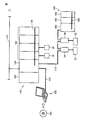
- FIG. 1 is a schematic diagram showing a system configuration of a control system 1 according to the present embodiment.
- control system 1 includes a PLC 100 and a support device 300 connected to PLC 100.
- the PLC 100 executes a user program as will be described later periodically or in an event manner.
- the support device 300 is a typical example of an information processing device that can be connected to the PLC 100.
- the support device 300 is connected to the PLC 100 via the connection cable 114 and provides functions such as setting various parameters, programming, monitoring, and debugging with the PLC 100.
- the PLC 100 and the support device 300 are configured to be communicable according to the USB (Universal Serial Bus) standard.
- USB Universal Serial Bus
- the PLC 100 includes a CPU unit 104 that executes control calculation and one or more IO (Input / Output) units 106. These units are configured to exchange data with each other via the PLC system bus 108. These units are supplied with power of an appropriate voltage by the power supply unit 102.
- IO Input / Output
- the PLC 100 exchanges data with various field devices via the IO unit 106 (connected via the PLC system bus 108) and / or via the field bus 110.
- These field devices include an actuator for performing some processing on the control target, a sensor for acquiring various information from the control target, and the like.
- FIG. 1 includes a servo motor driver 30 that drives the detection switch 10, the relay 20, and the motor 32 as an example of such a field device.
- the PLC 100 is also connected to the remote IO terminal 200 via the field bus 110.
- the remote IO terminal 200 basically performs processing related to general input / output processing in the same manner as the IO unit 106. More specifically, the remote IO terminal 200 includes a communication coupler 202 for performing processing related to data transmission via the field bus 110 and one or more IO units 204. These units are configured to exchange data with each other via the remote IO terminal bus 208.
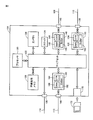
- FIG. 2 is a schematic diagram showing a hardware configuration showing a main part of PLC 100 according to the present embodiment.
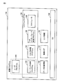
- FIG. 3 is a schematic diagram showing a software configuration of PLC 100 according to the present embodiment.
- the hardware configuration of the CPU unit 104 of the PLC 100 will be described with reference to FIG.
- the CPU unit 104 includes a processor 120, a chip set 122, a system clock 124, a main memory 126, a nonvolatile memory 128, a USB connector 130, a PLC system bus controller 140, a field bus controller 150, and higher-level communication.
- a controller 160 and a memory card interface 170 are included.
- the chip set 122 and other components are coupled via various buses.
- the processor 120 and the chip set 122 are typically configured according to a general-purpose computer architecture. That is, the processor 120 interprets and executes the instruction codes sequentially supplied from the chip set 122 according to the internal clock.
- the chip set 122 exchanges internal data with various connected components and generates instruction codes necessary for the processor 120.
- the system clock 124 generates a system clock having a predetermined period and provides it to the processor 120.
- the chip set 122 has a function of caching data obtained as a result of execution of arithmetic processing by the processor 120.
- the CPU unit 104 has a main memory 126 and a nonvolatile memory 128 as storage means.
- the main memory 126 is a volatile storage area, holds various programs to be executed by the processor 120, and is also used as a working memory when executing the various programs.
- the nonvolatile memory 128 holds an OS (Operating System), a system program, a user program, data definition information, log information, and the like in a nonvolatile manner.
- OS Operating System
- the USB connector 130 is an interface for connecting the support device 300 and the CPU unit 104. Typically, an executable program or the like transferred from the support device 300 is taken into the CPU unit 104 via the USB connector 130.
- the CPU unit 104 includes a PLC system bus controller 140, a field bus controller 150, and a host communication controller 160 as communication means. These communication circuits transmit and receive data.
- the PLC system bus controller 140 controls data exchange via the PLC system bus 108. More specifically, the PLC system bus controller 140 includes a buffer memory 142, a PLC system bus control circuit 144, and a DMA (Dynamic Memory Access) control circuit 146. The PLC system bus controller 140 is connected to the PLC system bus 108 via the PLC system bus connector 148.
- DMA Dynamic Memory Access
- the fieldbus controller 150 includes a buffer memory 152, a fieldbus control circuit 154, and a DMA control circuit 156.
- the field bus controller 150 is connected to the field bus 110 via the field bus connector 158.
- the upper communication controller 160 includes a buffer memory 162, an upper communication control circuit 164, and a DMA control circuit 166.
- the host communication controller 160 is connected to the network 112 via the host communication connector 168.
- the memory card interface 170 connects a memory card 172 detachable to the CPU unit 104 and the processor 120.
- the software executed by CPU unit 104 has three layers of OS 180, system program 188, and user program 186.
- the OS 180 provides a basic execution environment for the processor 120 to execute the system program 188 and the user program 186.
- the system program 188 is a software group for providing basic functions as the PLC 100. Specifically, the system program 188 includes a sequence instruction program 190, an input / output processing program 194, a Tool interface processing program 196, and a scheduler 198.
- the user program 186 is a program arbitrarily created according to the control purpose for the control target. That is, the user program 186 is arbitrarily designed according to the line (process) to be controlled using the control system 1.
- the user program 186 realizes a control purpose for the user in cooperation with the sequence command program 190. That is, the user program 186 realizes a programmed operation by using instructions, functions, function modules, and the like provided by the sequence instruction program 190. Therefore, the user program 186 and the sequence command program 190 may be collectively referred to as “control program”.
- the data definition information 182 includes a definition for handling data (input data, output data, internal data) referred to as a unique variable when the user program 186 or the like is executed.
- a definition for handling data input data, output data, internal data
- information on the generated event is stored in association with time information.
- the operation log 184 stores various information associated with the execution of the system program 188 and / or the user program 186 as a log (history information).
- the link information 185 is information in which a predetermined event is associated with designation of a variable related to this event.
- the sequence instruction program 190 includes an instruction code group for calling the substance of the sequence instruction specified in the user program 186 and realizing the contents of the instruction as the user program 186 is executed.
- the input / output processing program 194 is a program for managing the acquisition of input data and the transmission of output data with the IO unit 106 and various field devices.
- the Tool interface processing program 196 provides an interface for exchanging data with the support device 300.
- the scheduler 198 generates a thread and a procedure for executing the control program in accordance with a predetermined priority, a system timer value, and the like.
- the user program 186 is created according to a control purpose (for example, a target line or process) by the user.
- the user program 186 is typically in an object program format that can be executed by the processor 120 of the CPU unit 104.
- the user program 186 is generated by compiling a source program described in a ladder format or a function block format in the support device 300 or the like.
- the generated user program in the object program format is transferred from the support device 300 to the CPU unit 104 and stored in the nonvolatile memory 128 or the like.
- the support device 300 is for supporting the use of the CPU unit 104 of the PLC 100, and provides functions such as setting of various parameters, programming, monitoring, and debugging with the PLC 100.
- FIG. 4 is a schematic diagram showing a hardware configuration of the support device 300 used by being connected to the PLC 100 according to the present embodiment.
- the support device 300 is typically composed of a general-purpose computer.
- the support device 300 stores a CPU 302 that executes various programs including an OS, a ROM (Read Only Memory) 304 that stores BIOS and various data, and data necessary for the execution of the program by the CPU 302.
- a memory RAM 306 that provides a work area for storage
- a hard disk (HDD) 308 that stores programs executed by the CPU 302 in a nonvolatile manner. More specifically, the hard disk 308 stores a support program 330 for realizing functions provided by the support device 300.
- the support device 300 further includes a keyboard 310 and a mouse 312 that receive operations from the user, and a monitor 314 for presenting information to the user. Further, the support device 300 includes a communication interface (IF) 318 for communicating with the PLC 100 (CPU unit 104) and the like.
- IF communication interface
- the support program 330 executed by the support device 300 is stored in the optical recording medium 332 and distributed.
- the program stored in the optical recording medium 332 is read by the optical disk reader 316 and stored in the hard disk 308 or the like.
- the program may be downloaded from a host computer or the like via a network.
- the log output function according to the present embodiment is output when a normal program execution log (hereinafter also referred to as “execution log”), a program execution failure, or a hardware failure occurs.
- execution log a normal program execution log
- execution failure a program execution failure
- hardware failure a hardware failure occurs.
- event log it is possible to output a log having a position and content arbitrarily specified in the user program 186 (hereinafter also referred to as “debug log”). Yes.
- the operation log 184 includes all these logs.
- the event log is information that records the processing contents in association with time information when execution of the specified processing fails. Typically, when a specified process is interrupted due to an error or the like, the contents are logged.
- the CPU unit 104 When the CPU unit 104 detects the occurrence of the event in response to the occurrence of a predetermined event by executing the system program 188, the CPU unit 104 links the information (event log) of the event that has occurred and time information.
- the current value of the variable set by the information 185 is stored in association with it.
- the CPU unit 104 stores the value of the variable designated by the user set by the link information 185 in a predetermined area of the nonvolatile memory 128 at a certain timing designated by the user. At this time, the nonvolatile memory 128 functions as a ring buffer and cyclically stores variable values.
- the CPU unit 104 stores the value of the variable for the time set in the link information 185 with respect to the value of the variable that has been sequentially stored based on the time when the event occurred. To do.
- FIG. 5 is a diagram for explaining the outline of the log output function of the CPU unit 104 according to the present embodiment.
- the CPU unit 104 functions as a control unit 901, a logging unit 903, a setting unit 905, an event log storage unit 907, a variable storage unit 909, and a storage unit 911.
- the storage unit 911 stores a logging result 913 and event data 915.
- the control unit 901 controls the entire operation of the PLC 100.
- the control unit 901 controls the operation of the entire system, such as program execution, field network, host network, data communication via a bus, and self-diagnosis of the PLC 100 itself.
- the occurrence of an event may be a configuration in which the control unit itself monitors, or a configuration in which error information is notified from a connected device.
- the logging unit 903 cyclically stores the set variable values in the storage unit 911 according to the settings received from the support device 300 by the setting unit 905.
- the logging unit 903 detects occurrence of a predetermined event, the logging unit 903 stores the value of the variable that has been stored cyclically in the logging result 913.
- the event log storage unit 907 When the event log storage unit 907 detects the occurrence of an event, the event log storage unit 907 stores the event type and the time information in the storage unit 911 in association with each other. When the occurrence of the event set by the setting unit 905 is detected, the event log storage unit 907 accesses the variable storage unit 909, reads the current value of the variable, and stores the current value of the variable in addition to the event type and the occurrence time. Store in the unit 911. Further, the address that the logging unit 903 stores in the logging result 913 is stored as address link information.
- the setting unit 905 accepts setting of information on an event to be recorded as an event log from the support device 300. In addition, the setting unit 905 receives a designation of a variable to be logged from the support device 300. The setting unit 905 sets variables to be stored in association with variable values in the logging unit 903 and the event log storage unit 907.
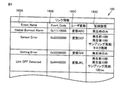
- FIG. 6 is a diagram showing the link information 185. As shown in FIG. 6, each record of the link information 185 includes an event name 185A, an event code 185B that is identification information for identifying each event, a variable 185C, and a recording setting 185D.
- the event name 185A indicates the name of each predetermined event (eg, normal program execution, program execution failure, hardware malfunction, etc.).
- the event code 185B is information for identifying each event.
- a variable 185C indicates a variable designated by the user as a variable related to the event.
- the record setting 185D indicates the range of time information to be displayed on the monitor 314 of the value of the variable designated by the user.
- the time information range for example, the value of the variable in the time information at which the event occurred is displayed (record setting “only when it occurs”), or the value of the variable within a predetermined time before and after the time information at which the event occurred (Recording setting “X seconds before occurrence”, recording setting “X seconds after occurrence” (“X” is an arbitrary number)), and the like.
- FIG. 7 is a diagram illustrating an example of a user interface that receives an input operation for editing the link information 185 provided in the support device 300 according to the present embodiment.
- the support apparatus 300 displays a setting screen 340 on the monitor 314.
- the setting screen 340 is a screen for the user to set a range of time information for accepting designation of a variable by the user for each predetermined event and displaying the value of the variable.
- the category 342 indicates a category in which each predetermined event is included.
- the category for example, each unit constituting the control device is shown.
- the event name 343 indicates the name of each predetermined event.
- the event code 344 is information for identifying each event.
- the setting 346 indicates a variable associated with each event and a range of time information for displaying the value of the variable based on the time information of the event. For example, when the setting 346 indicates “only when it occurs”, the value of the variable at the same time as the time information when the event name 343 and the event code 344 are generated is the target to be displayed on the monitor 314. When the setting 346 indicates “10 seconds before the occurrence, 10 seconds after the occurrence”, the values of the variables in the 10-second period before and after the time information at which the event name 343 and the event code 344 occurred are represented as the event. Associated. As described above, the support device 300 receives an input operation for editing the correspondence between the event and the designation of the variable, and generates link information 185 according to the input operation.
- the support apparatus 300 transmits the generated link information 185 to the PLC 100.
- the PLC 100 receives the link information 185 from the support device 300, the PLC 100 stores it in the memory card 172 or the like.
- the PLC 100 transmits the operation log 184 and the link information 185 to the support device 300.
- the sampling timing 347 indicates the setting of the sampling timing when the sampling result of the variable value before and after the occurrence of the event is to be displayed on the monitor 314.
- the sampling timing includes a timing according to a task cycle, a timing designated by the user (for example, every 100 ms), and the like.
- FIG. 8 is a flowchart showing a processing procedure in the PLC 100 according to the present embodiment. Each step shown in FIG. 8 is realized by the processor 120 of the CPU unit 104 executing the user program 186 and the system program 188, respectively. Although an example in which the user program 186 and the system program 188 are executed independently of each other is shown, a single program including both programs may be executed.
- processor 120 loads user program 186 stored in advance, and repeatedly executes the loaded user program 186 at a predetermined cycle (step S100). It is assumed that the user program 186 to be loaded is in an object format that can be compiled and executed. However, the user program 186 may be loaded as the source code, or the user program 186 compiled into intermediate code may be loaded. In this case, the processor 120 executes processing while sequentially compiling the loaded code.
- the processor 120 executes the specified process while calling the system program 188 as necessary in accordance with an instruction included in the user program 186 (step S102).
- the processor 120 designates The value of the variable is cyclically stored in the nonvolatile memory according to the sampling timing.
- step S108 when a predetermined event such as an error occurs (YES in step S108), the processor 120 associates the information such as the error with the time information and the current value of the variable value as an event log. Output (step S110).
- step S102 When the execution of the series of user programs 186 is completed, the processing after step S102 is repeated.
- FIG. 9 is a flowchart showing a processing procedure in the PLC 100 according to the present embodiment.
- processor 120 loads system program 188 stored in advance, and repeatedly executes loaded system program 188 at a predetermined cycle (step S200). It is assumed that the loaded system program 188 is in an object format that can be compiled and executed. However, as with the user program 186, the system program 188 may be loaded as the source code, or may be loaded into the intermediate code.
- the processor 120 determines whether transmission of the operation log 184 is requested from the support device 300 (step S202). If transmission of the operation log 184 is requested from the support device 300 (YES in step S202), the processor 120 reads the stored operation log 184 and transmits it to the support device 300 (step S204). In step S ⁇ b> 206, the processor 120 transmits the link information 185 to the support device 300.
- steps S202, S204, and S206 is processing when acquisition of the operation log 184 is requested from the support device 300.
- step S202 When the execution of the series of system programs 188 is completed, the processing after step S202 is repeated.
- the support device 300 displays the event log included in the operation log 184 on the monitor 314. The user can check the event log through a user interface displayed on the support device 300.
- the support device 300 provides a user interface that displays information stored in a storage unit (such as the memory card 172) of the PLC 100 in time series.
- FIG. 10 is a diagram illustrating an example of a user interface related to acquisition and display of the operation log 184 provided in the support device 300 according to the present embodiment.
- the operation log 184 and the link information 185 are acquired from the PLC 100 connected to the support device 300.
- the operation log 184 and the link information 185 are basically transmitted from the PLC 100 to the support device 300 via the USB connector 130.
- the present invention is not limited to this, and transmission may be performed via a network using an FTP (File Transfer Protocol) server function or an HTTP (Hyper Text Transfer Protocol) server function provided by the PLC 100.
- the event log is displayed in time series on the user interface screen 341 shown in FIG. As an example, among the operation logs illustrated in FIG. 10, the log 354 of the entry “1018” is generated by the event name “Power off”.
- each log includes items such as entry, date / time, importance, source, source details, and event name.
- the date and time indicate the time when the corresponding event occurs.
- the entry is information for identifying each log.
- the date and time indicates time information when each event occurs in the event log.
- the importance level indicates the importance level of each event.
- the generation source indicates a generation source in which an event has occurred. For example, the generation source indicates the generation source for the entire apparatus or for each component unit.
- the generation source details indicate more detailed information (parts, processing, etc.) in the generation source.
- the event name is information for identifying each event.
- the log 351 of the entry “1021” is a log related to the event name “link-off detection”.
- the log 352 of the entry “1020” is a log related to the event name “operation start”.
- the log “353” of the entry “1019” is a log related to the event name “power on”.
- the log 354 of the entry “1018” is selected by the user's input operation.
- the support apparatus 300 refers to the link information 185, and when a variable related to the event is associated with the event corresponding to the entry selected by the user, the information indicating the variable is displayed on the user interface screen 341 as “ Displayed as “Attached information”.
- the support device 300 When the support device 300 receives an input operation to the display switching button 361 in a state where the log is selected (the log 354 is selected), the support device 300 relates to an event (event name) indicated in the selected log. If there is, display the value of the variable.
- the support apparatus 300 acquires the operation log 184 from the PLC 100, and displays the information of the event recorded as the log indicated in the acquired operation log 184 on the monitor 314. Further, the support apparatus 300 displays, on the monitor 314, information indicating a variable associated with event information recorded as a log, which is indicated in the operation log 184, based on the link information 185.
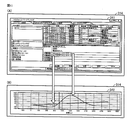
- FIG. 11 is a diagram showing the transition of the user interface screen.
- FIG. 11A shows a user interface screen 341.
- the support device 300 refers to the link information 185, and if there is a variable related to the event (event name) shown in the log, the information indicating the variable is “attached”. Information "is displayed.
- the support device 300 displays the value of a variable related to the event (event name).
- FIG. 11B is a diagram illustrating an example of displaying values of variables related to events. In FIG.
- the user interface screen 352 is displayed over a certain period of time before and after the time information at which the event was logged for variables associated with the event (for example, “attachment information 1” and “attachment information 2”). The value shown in the debug log is displayed.
- the PLC 100 automatically outputs an event log. Then, the user can refer to the operation log stored in time series in this way.
- the PLC 100 stores link information 185, and when the support device 300 requests the operation log 184 of the PLC 100, the operation log 184 and the link information 185 are transmitted from the PLC 100 to the support device 300.
- the support device 300 displays the event log included in the operation log 184 on the monitor 341 and, if a variable related to the event included in the operation log 184 is designated, displays the variable on the monitor 341 as well. Since the link information 185 defines the correspondence between the event and the user variable by the user himself / herself, when the user refers to the event log later, it is easy to check the value of the user variable related to the event. .
- the user can easily identify what is the cause when a predetermined event (for example, a malfunction of a program, a power failure, etc.) occurs. This makes it possible to efficiently debug the program and check the soundness.
- a predetermined event for example, a malfunction of a program, a power failure, etc.
Abstract
制御装置(104)は、予め定められた事象と、当該事象に関連する変数とを対応付けたリンク情報(185)を記憶する。制御装置(104)は、予め定められた事象(905)の発生に応答して、発生した事象の情報と、リンク情報(185)に示される、事象に関連する所定の変数の現在値とを、時刻情報と関連付けて第1のログ情報としてメモリ(911)に記憶させる。また、制御装置(104)は、予め定められた周期に従って、所定の変数の値を含む情報と時刻情報とを関連付けて第2のログ情報としてメモリ(128)に記憶させる。情報処理装置(300)は、リンク情報(185)を制御装置から取得し、リンク情報と第2のログ情報とに基づいて、第1のログ情報に示される事象の情報と対応付けられる変数を示す情報をモニタ(314)に表示する。
Description
本発明は、ユーザプログラムを周期的またはイベント的に実行する制御装置を含む制御システムおよび制御システムの情報処理装置に関する。
多くの生産現場で使用される機械や設備は、典型的には、プログラマブルコントローラ(Programmable Logic Controller;以下「PLC」とも称す)などの制御装置を主たる構成とした制御システムによって制御される。このような制御システムでは、システム構成時や運転時に発生した不具合を事後的に検証できるように、各種のログ出力機能が搭載されている。
また、PLCは、ユーザプログラムの実行に伴う変数の変化についてデータトレースすることを可能とするため、例えばユーザプログラムに含まれるトレースサンプリング命令が実行された場合に、ユーザプログラムにおいて参照および更新される変数を収集するよう構成されている。例えば、プログラミングのデバッグを目的に、変数のトレースが行われる。例えば、プログラムの実行に際し、プログラミング実行やデータの入力があったタイミングでデータを収集することが行われている。
このような機能を搭載した制御装置に関する先行技術文献として、特開2012-194680号公報(特許文献1)は、機器の動作を制御するPLCにおいて、ユーザプログラムにトレースサンプリング命令が含まれている場合に、どのトレースサンプリング命令によりどの収集結果が得られたのかを利用者が判断することができる技術を記載している。
制御装置は、プログラムの実行や、ネットワークの通信状態や、外部環境の状況に応じて種々のイベントが発生する。イベントが発生した場合において、そのイベントの要因を特定し、そのイベント発生時のPLCの動作状態を再現し、イベント発生の直前のPLCの動作状態の確認すること等を目的に、変数の状態を知ることが必要となることがある。
しかし、従来の制御装置においては、イベント発生時刻を基準として、そのイベントに関連する変数の値のデータ列を参照し、イベントの発生時刻やイベントの内容と照合することでデータを確認する必要があり、煩雑な手順が必要となる。
そこで、本発明は、イベントの発生時において、そのイベントの要因の発生時における制御装置の状態を容易に知ることができる制御システム、方法、プログラムおよび情報処理装置を提供することを目的とする。
本発明のある局面に係る制御システムは、ユーザプログラムを周期的またはイベント的に実行する制御装置と、制御装置に接続可能な情報処理装置とを備える。制御装置は、予め定められた事象と、当該事象に関連する変数とを対応付けたリンク情報を記憶するための第1の記憶部と、予め定められた事象の発生に応答して、当該発生した事象の情報と、リンク情報に示される、当該事象に関連する所定の変数の現在値とを、時刻情報と関連付けて第1のログ情報として第1の記憶部に書き込むための第1の書き込み部と、予め定められた周期に従って、所定の変数の値を含む情報と時刻情報とを関連付けて第2のログ情報として第1の記憶部に書き込むための第2の書き込み部とを備える。情報処理装置は、第1のログ情報および第2のログ情報を制御装置から取得する通信部と、情報を表示するためのモニタと、リンク情報を記憶するための第2の記憶部と、情報処理装置の動作を制御する制御部とを備える。制御部は、通信部により取得した第1のログ情報に示される発生した事象の情報及びリンク情報に示される、事象に関連する変数の、事象の発生の際の当該事象に関連する所定の変数の値をモニタに表示させるログ表示部と、リンク情報と第2のログ情報とに基づいて、第1のログ情報に示される発生した事象の情報と対応付けられる所定の変数の値を示す情報を、モニタに表示させるリンク表示部とを含む。
好ましくは、情報処理装置の制御部は、事象と、変数の指定との対応関係を編集する入力操作に応じてリンク情報を生成するリンク情報生成部を含み、通信部により生成したリンク情報を制御装置へ送信する。制御装置は、情報処理装置からリンク情報を受信して記憶し、情報処理装置から、第1のログ情報および第2のログ情報の要求を受け付けると、第1のログ情報、第2のログ情報およびリンク情報を情報処理装置へ送信し、情報処理装置の制御部は、制御装置からリンク情報を受信して、受信したリンク情報を第2の記憶部に記憶させる。
好ましくは、情報処理装置のリンク表示部は、第1のログ情報に示される発生した事象の情報と対応付けられる変数の値をモニタに表示するための入力操作に応じて、当該変数の値をモニタに表示させる。
好ましくは、リンク情報は、事象と対応付けられる変数の値の時刻情報の範囲を含み、制御部は、事象と、変数の指定との対応関係を編集する入力操作に応じて、事象と対応付けられる変数の値の時刻情報の範囲を含むリンク情報を生成し、リンク表示部は、発生した事象の情報と対応付けられる変数の値を、リンク情報に示される時刻情報の範囲に従ってモニタに表示させる。
別の実施形態に従うと、制御システムのログを表示するための方法が提供される。制御システムは、ユーザプログラムを周期的またはイベント的に実行する制御装置と、制御装置に接続可能な情報処理装置とを備える。制御装置は、予め定められた事象と、当該事象に関連する変数とを対応付けたリンク情報を記憶するための第1の記憶部を備え、情報処理装置は、リンク情報を記憶するための第2の記憶部と、モニタとを備える。方法は、制御装置が、予め定められた事象の発生に応答して、当該発生した事象の情報と、リンク情報に示される、当該事象に関連する所定の変数の現在値とを、時刻情報と関連付けて第1のログ情報として第1の記憶部に書き込むステップと、制御装置が、予め定められた周期に従って、所定の変数の値を含む情報と時刻情報とを関連付けて第2のログ情報として第1の記憶部に書き込むステップと、情報処理装置が、第1のログ情報および第2のログ情報を制御装置から取得するステップと、情報処理装置が、取得した第1のログ情報に示される発生した事象の情報及びリンク情報に示される、事象に関連する変数の、事象の発生の際の当該事象に関連する所定の変数の値をモニタに表示するステップと、情報処理装置が、リンク情報と第2のログ情報とに基づいて、第1のログ情報に示される発生した事象の情報と対応付けられる所定の変数の値を示す情報をモニタに表示するステップとを含む。
別の実施形態に従うと、ユーザプログラムを周期的またはイベント的に実行する制御装置と、制御装置に接続可能な情報処理装置とにより構成される制御システムの情報処理装置が提供される。制御装置は、予め定められた事象と、当該事象に関連する変数とを対応付けたリンク情報を記憶するための第1の記憶部と、予め定められた事象の発生に応答して、当該発生した事象の情報と、リンク情報に示される、当該事象に関連する所定の変数の現在値と、時刻情報とを関連付けて第1のログ情報として第1の記憶部に書き込むための第1の書き込み部と、予め定められた周期に従って、所定の変数の値を含む情報と時刻情報とを関連付けて第2のログ情報として第1の記憶部に書き込むための第2の書き込み部とを備える。情報処理装置は、第1のログ情報および第2のログ情報を制御装置から取得する通信部と、情報を表示するためのモニタと、リンク情報を記憶するための第2の記憶部と、情報処理装置の動作を制御する制御部とを備える。制御部は、通信部により取得した第1のログ情報に示される発生した事象の情報及びリンク情報に示される、事象に関連する変数の、事象の発生の際の当該事象に関連する所定の変数の値をモニタに表示させるログ表示部と、リンク情報と第2のログ情報とに基づいて、第1のログ情報に示される発生した事象の情報と対応付けられる所定の変数の値を示す情報を、モニタに表示させるリンク表示部とを含む。
別の実施形態に従うと、ユーザプログラムを周期的またはイベント的に実行する制御装置と、制御装置に接続可能な情報処理装置とにより構成される制御システムの、情報処理装置の動作を制御するためのプログラムが提供される。制御装置は、予め定められた事象と、当該事象に関連する変数とを対応付けたリンク情報を記憶するための第1の記憶部と、予め定められた事象の発生に応答して、当該発生した事象の情報と、リンク情報に示される、当該事象に関連する所定の変数の現在値と、時刻情報とを関連付けて第1のログ情報として第1の記憶部に書き込むための第1の書き込み部と、予め定められた周期に従って、所定の変数の値を含む情報と時刻情報とを関連付けて第2のログ情報として第1の記憶部に書き込むための第2の書き込み部とを備える。情報処理装置は、事象と、変数の指定とを対応付けたリンク情報を記憶するための第2の記憶部、プロセッサ、およびモニタを備える。プログラムは、プロセッサに、第1のログ情報および第2のログ情報を制御装置から取得するステップと、取得した第1のログ情報に示される発生した事象の情報をモニタに表示するステップと、リンク情報と第2のログ情報とに基づいて、第1のログ情報に示される発生した事象の情報と対応付けられる変数を示す情報をモニタに表示するステップとを実行させる。
本発明によれば、イベントの発生時において、そのイベントの発生時における制御装置の状態を容易に知ることができ、プログラムのデバッグ等を効率的に行うことができる。
本発明の実施の形態について、図面を参照しながら詳細に説明する。なお、図中の同一または相当部分については、同一符号を付してその説明は繰り返さない。
<A.システム構成>
まず、本実施の形態に係る制御システムのシステム構成について説明する。本実施の形態においては、機械や設備などの制御対象を制御するプログラマブルコントローラ(PLC)を制御装置の典型例として説明を行う。但し、本発明に係る制御装置は、PLCに限られることなく、各種の制御装置へ適用可能である。
まず、本実施の形態に係る制御システムのシステム構成について説明する。本実施の形態においては、機械や設備などの制御対象を制御するプログラマブルコントローラ(PLC)を制御装置の典型例として説明を行う。但し、本発明に係る制御装置は、PLCに限られることなく、各種の制御装置へ適用可能である。
図1は、本実施の形態に係る制御システム1のシステム構成を示す模式図である。図1を参照して、制御システム1は、PLC100と、PLC100に接続されるサポート装置300とを含む。PLC100は、後述するようなユーザプログラムを周期的またはイベント的に実行する。
サポート装置300は、PLC100に接続可能な情報処理装置の典型例である。サポート装置300は、接続ケーブル114を介してPLC100に接続され、PLC100との間で各種パラメータの設定、プログラミング、モニタ、デバッグなどの機能を提供する。PLC100とサポート装置300との間は、典型的には、USB(Universal Serial Bus)規格に従って通信可能に構成される。
PLC100は、制御演算を実行するCPUユニット104と、1つ以上のIO(Input/Output)ユニット106とを含む。これらのユニットは、PLCシステムバス108を介して、データを互いに遣り取りできるように構成される。また、これらのユニットには、電源ユニット102によって適切な電圧の電源が供給される。
制御システム1において、PLC100は、(PLCシステムバス108を介して接続される)IOユニット106を介して、および/または、フィールドバス110を介して、各種のフィールド機器との間でデータを遣り取りする。これらのフィールド機器は、制御対象に対して何らかの処理を行うためのアクチュエータや、制御対象から各種情報を取得するためのセンサなどを含む。図1には、このようなフィールド機器の一例として、検出スイッチ10、リレー20およびモータ32を駆動するサーボモータドライバ30を含む。また、PLC100は、フィールドバス110を介してリモートIOターミナル200も接続されている。リモートIOターミナル200は、基本的には、IOユニット106と同様に、一般的な入出力処理に関する処理を行う。より具体的には、リモートIOターミナル200は、フィールドバス110でのデータ伝送に係る処理を行うための通信カプラ202と、1つ以上のIOユニット204とを含む。これらのユニットは、リモートIOターミナルバス208を介して、データを互いに遣り取りできるように構成される。
<B.PLC100の構成>
次に、本実施の形態に係るPLC100の構成について説明する。図2は、本実施の形態に係るPLC100の主要部を示すハードウェア構成を示す模式図である。図3は、本実施の形態に係るPLC100のソフトウェア構成を示す模式図である。
次に、本実施の形態に係るPLC100の構成について説明する。図2は、本実施の形態に係るPLC100の主要部を示すハードウェア構成を示す模式図である。図3は、本実施の形態に係るPLC100のソフトウェア構成を示す模式図である。
図2を参照して、PLC100のCPUユニット104のハードウェア構成について説明する。CPUユニット104は、プロセッサ120と、チップセット122と、システムクロック124と、主メモリ126と、不揮発性メモリ128と、USBコネクタ130と、PLCシステムバスコントローラ140と、フィールドバスコントローラ150と、上位通信コントローラ160と、メモリカードインターフェイス170とを含む。チップセット122と他のコンポーネントとの間は、各種のバスを介してそれぞれ結合されている。
プロセッサ120およびチップセット122は、典型的には、汎用的なコンピュータアーキテクチャに準じて構成される。すなわち、プロセッサ120は、チップセット122から内部クロックに従って順次供給される命令コードを解釈して実行する。チップセット122は、接続されている各種コンポーネントとの間で内部的なデータを遣り取りするとともに、プロセッサ120に必要な命令コードを生成する。システムクロック124は、予め定められた周期のシステムクロックを発生してプロセッサ120に提供する。チップセット122は、プロセッサ120での演算処理の実行の結果得られたデータなどをキャッシュする機能を有する。
CPUユニット104は、記憶手段として、主メモリ126および不揮発性メモリ128を有する。主メモリ126は、揮発性の記憶領域であり、プロセッサ120で実行されるべき各種プログラムを保持するとともに、各種プログラムの実行時の作業用メモリとしても使用される。不揮発性メモリ128は、OS(Operating System)、システムプログラム、ユーザプログラム、データ定義情報、ログ情報などを不揮発的に保持する。
USBコネクタ130は、サポート装置300とCPUユニット104とを接続するためのインターフェイスである。典型的には、サポート装置300から転送される実行可能なプログラムなどは、USBコネクタ130を介してCPUユニット104に取込まれる。
CPUユニット104は、通信手段として、PLCシステムバスコントローラ140、フィールドバスコントローラ150、および上位通信コントローラ160を有する。これらの通信回路は、データの送信および受信を行う。
PLCシステムバスコントローラ140は、PLCシステムバス108を介したデータの遣り取りを制御する。より具体的には、PLCシステムバスコントローラ140は、バッファメモリ142と、PLCシステムバス制御回路144と、DMA(Dynamic Memory Access)制御回路146とを含む。PLCシステムバスコントローラ140は、PLCシステムバスコネクタ148を介してPLCシステムバス108と接続される。
フィールドバスコントローラ150は、バッファメモリ152と、フィールドバス制御回路154と、DMA制御回路156とを含む。フィールドバスコントローラ150は、フィールドバスコネクタ158を介してフィールドバス110と接続される。上位通信コントローラ160は、バッファメモリ162と、上位通信制御回路164と、DMA制御回路166とを含む。上位通信コントローラ160は、上位通信コネクタ168を介してネットワーク112と接続される。
メモリカードインターフェイス170は、CPUユニット104に対して着脱可能なメモリカード172とプロセッサ120とを接続する。
次に、図3を参照して、本実施の形態に係るPLC100が提供する各種機能を実現するためのソフトウェア構成について説明する。これらのソフトウェアに含まれる命令コードは、適切なタイミングで読み出され、CPUユニット104のプロセッサ120によって実行される。
図3を参照して、CPUユニット104で実行されるソフトウェアとしては、OS180と、システムプログラム188と、ユーザプログラム186との3階層になっている。
OS180は、プロセッサ120がシステムプログラム188およびユーザプログラム186を実行するための基本的な実行環境を提供する。
システムプログラム188は、PLC100としての基本的な機能を提供するためのソフトウェア群である。具体的には、システムプログラム188は、シーケンス命令プログラム190と、入出力処理プログラム194と、Toolインターフェイス処理プログラム196と、スケジューラ198とを含む。
これに対して、ユーザプログラム186は、制御対象に対する制御目的に応じて任意に作成されたプログラムである。すなわち、ユーザプログラム186は、制御システム1を用いて制御する対象のライン(プロセス)などに応じて、任意に設計される。
ユーザプログラム186は、シーケンス命令プログラム190と協働して、ユーザにおける制御目的を実現する。すなわち、ユーザプログラム186は、シーケンス命令プログラム190によって提供される命令、関数、機能モジュールなどを利用することで、プログラムされた動作を実現する。そのため、ユーザプログラム186およびシーケンス命令プログラム190を「制御プログラム」と総称する場合もある。
データ定義情報182は、ユーザプログラム186などが実行される際に、参照されるデータ(入力データ、出力データ、内部データ)をユニークな変数として扱うための定義を含む。稼働ログ184には、システムプログラム188およびユーザプログラム186の実行に伴って、予め定められた事象が発生した際に、当該発生した事象の情報が時刻情報と関連付けて格納される。すなわち、稼働ログ184には、システムプログラム188および/またはユーザプログラム186の実行に伴う各種情報がログ(履歴情報)として格納される。リンク情報185は、予め定められた事象と、この事象に関連する変数の指定とを対応付けた情報である。
以下、各プログラムについてより詳細に説明する。
シーケンス命令プログラム190は、ユーザプログラム186の実行に伴って、ユーザプログラム186内で指定されているシーケンス命令の実体を呼び出して、その命令の内容を実現するための命令コード群を含む。
シーケンス命令プログラム190は、ユーザプログラム186の実行に伴って、ユーザプログラム186内で指定されているシーケンス命令の実体を呼び出して、その命令の内容を実現するための命令コード群を含む。
入出力処理プログラム194は、IOユニット106や各種のフィールド機器との間で、入力データの取得および出力データの送信を管理するためのプログラムである。
Toolインターフェイス処理プログラム196は、サポート装置300との間でデータを遣り取りするためのインターフェイスを提供する。
スケジューラ198は、予め定められた優先度やシステムタイマの値などに従って、制御プログラムを実行するためのスレッドやプロシージャを生成する。
ユーザプログラム186は、上述したように、ユーザにおける制御目的(たとえば、対象のラインやプロセス)に応じて作成される。ユーザプログラム186は、典型的には、CPUユニット104のプロセッサ120で実行可能なオブジェクトプログラム形式になっている。ユーザプログラム186は、サポート装置300などにおいて、ラダー形式やファンクションブロック形式で記述されたソースプログラムがコンパイルされることで生成される。そして、生成されたオブジェクトプログラム形式のユーザプログラムは、サポート装置300からCPUユニット104へ転送され、不揮発性メモリ128などに格納される。
<C.サポート装置300の構成>
次に、本実施の形態に係るサポート装置300について説明する。サポート装置300は、PLC100のCPUユニット104の使用を支援するためのものであり、PLC100との間で各種パラメータの設定、プログラミング、モニタ、デバッグなどの機能を提供する。
次に、本実施の形態に係るサポート装置300について説明する。サポート装置300は、PLC100のCPUユニット104の使用を支援するためのものであり、PLC100との間で各種パラメータの設定、プログラミング、モニタ、デバッグなどの機能を提供する。
図4は、本実施の形態に係るPLC100に接続して用いられるサポート装置300のハードウェア構成を示す模式図である。サポート装置300は、典型的には、汎用のコンピュータで構成される。
図4を参照して、サポート装置300は、OSを含む各種プログラムを実行するCPU302と、BIOSや各種データを格納するROM(Read Only Memory)304と、CPU302でのプログラムの実行に必要なデータを格納するための作業領域を提供するメモリRAM306と、CPU302で実行されるプログラムなどを不揮発的に格納するハードディスク(HDD)308とを含む。より具体的には、ハードディスク308には、サポート装置300が提供する機能を実現するためのサポートプログラム330が格納されている。
サポート装置300は、さらに、ユーザからの操作を受け付けるキーボード310およびマウス312と、情報をユーザに提示するためのモニタ314とを含む。さらに、サポート装置300は、PLC100(CPUユニット104)などと通信するための通信インターフェイス(IF)318を含む。
サポート装置300で実行されるサポートプログラム330などは、光学記録媒体332に格納されて流通する。光学記録媒体332に格納されたプログラムは、光学ディスク読取装置316によって読み取られ、ハードディスク308などへ格納される。あるいは、上位のホストコンピュータなどからネットワークを通じてプログラムをダウンロードするように構成してもよい。
<D.ログ出力機能の概要>
次に、本実施の形態に係る制御システム1により提供されるログ出力機能の概要について説明する。本実施の形態に係るログ出力機能は、通常のプログラムの実行に伴って出力されるログ(以下「実行ログ」とも称す。)や、プログラムの実行失敗やハードウェアの不具合の発生に伴って出力されるログ(以下「イベントログ」とも称す。)に加えて、ユーザプログラム186において任意に指定された位置および内容のログ(以下「デバッグログ」とも称す。)を出力することが可能になっている。稼働ログ184は、これらのすべてのログを含む。
次に、本実施の形態に係る制御システム1により提供されるログ出力機能の概要について説明する。本実施の形態に係るログ出力機能は、通常のプログラムの実行に伴って出力されるログ(以下「実行ログ」とも称す。)や、プログラムの実行失敗やハードウェアの不具合の発生に伴って出力されるログ(以下「イベントログ」とも称す。)に加えて、ユーザプログラム186において任意に指定された位置および内容のログ(以下「デバッグログ」とも称す。)を出力することが可能になっている。稼働ログ184は、これらのすべてのログを含む。
イベントログは、指定された処理の実行が失敗したような場合に、その処理内容を時刻情報と関連付けて記録した情報である。典型的には、指定された処理がエラーなどで中断したような場合に、その内容がロギングされる。
CPUユニット104は、システムプログラム188を実行することで、予め定められた事象の発生に応答して、当該事象の発生を検出した場合に当該発生した事象の情報(イベントログ)と時刻情報とリンク情報185で設定された変数の現在値とを関連付けて記憶する。CPUユニット104は、リンク情報185で設定されたユーザが指定した変数の値をユーザが指定した一定のタイミングで不揮発性メモリ128の所定の領域に格納する。この際不揮発性メモリ128は、リングバッファとして機能し循環的に変数の値を格納する。CPUユニット104は、予め定められた事象が発生した場合は、当該事象が発生した時刻を基準に順次格納していた変数の値についてリンク情報185で設定された時間分だけの変数の値を記憶する。
図5は、本実施の形態に係るCPUユニット104の、ログ出力機能の概要を説明するための図である。図5に示すように、CPUユニット104は、制御部901と、ロギング部903と、設定部905と、イベントログ格納部907と、変数記憶部909と、記憶部911として機能する。記憶部911は、ロギング結果913と、イベントデータ915とを記憶する。
制御部901は、PLC100の動作全体を制御する。制御部901はプログラムの実行やフィールドネットワーク、上位ネットワーク、バスを介したデータ通信、PLC100自身の自己診断など、システム全体の動作を制御する。事象の発生としては、制御部自身が監視を行っている構成でも良いし、接続されている機器からのエラー情報の通知を行う構成としても良い。
ロギング部903は、設定部905によってサポート装置300から受け付けた設定に従って、設定された変数の値を、記憶部911へ循環的に格納する。ロギング部903は、予め定められた事象の発生を検出すると、循環的に格納していた変数の値をロギング結果913に格納する。
イベントログ格納部907は、事象の発生を検出すると、記憶部911に、イベント種別と時刻情報とを対応づけて記憶する。イベントログ格納部907は、設定部905によって設定された事象の発生を検出すると、変数記憶部909にアクセスし、変数の現在値を読出し、イベント種別と発生時刻に加えて変数の現在値を記憶部911に記憶する。さらにロギング部903がロギング結果913に格納させるアドレスをアドレスリンク情報として格納する。
設定部905は、サポート装置300から、イベントログとして記録する対象となる事象の情報の設定を受け付ける。また、設定部905は、サポート装置300から、ロギングの対象となる変数の指定を受け付ける。設定部905は、ロギング部903、イベントログ格納部907に対して変数の値と対応づけて記憶する変数を設定する。
<E.リンク情報185のデータ構造>
図6を参照して、リンク情報185のデータ構造について説明する。
図6を参照して、リンク情報185のデータ構造について説明する。
図6は、リンク情報185を示す図である。図6に示すように、リンク情報185の各レコードは、イベント名185Aと、事象それぞれを識別するための識別情報であるイベントコード185Bと、変数185Cと、記録設定185Dとを含む。
イベント名185Aは、予め定められた事象(例えば、通常のプログラムの実行、プログラムの実行失敗、ハードウェアの不具合の発生など)のそれぞれの名称を示す。
イベントコード185Bは、事象それぞれを識別するための情報である。
変数185Cは、事象に関連する変数としてユーザが指定した変数を示す。
変数185Cは、事象に関連する変数としてユーザが指定した変数を示す。
記録設定185Dは、ユーザによって指定された変数の値の、モニタ314に表示すべき時刻情報の範囲を示す。時刻情報の範囲としては、例えば、事象が発生した時刻情報における変数の値を表示するか(記録設定「発生時のみ」)、事象が発生した時刻情報の前後の所定の時間内における変数の値を表示するか(記録設定「発生前X秒」、記録設定「発生後X秒」(”X”は任意の数))等がある。
<F.ユーザインターフェイス(リンク情報185の設定)>
次に、リンク情報185の設定に係るユーザインターフェイスについて説明する。このユーザインターフェイスは、本実施の形態に係るサポート装置300により提供される。
次に、リンク情報185の設定に係るユーザインターフェイスについて説明する。このユーザインターフェイスは、本実施の形態に係るサポート装置300により提供される。
図7は、本実施の形態に係るサポート装置300において提供される、リンク情報185の編集をするための入力操作を受け付けるユーザインターフェイスの一例を示す図である。
図7に示すように、サポート装置300は、モニタ314に、設定画面340を表示する。設定画面340は、予め定められた事象それぞれについて、ユーザにより変数の指定を受け付けて、変数の値を表示する時刻情報の範囲をユーザが設定するための画面である。
カテゴリ342は、予め定められた事象それぞれが含まれるカテゴリを示す。カテゴリとしては、例えば、制御機器を構成する各ユニットを示す。
イベント名343は、予め定められた事象のそれぞれの名称を示す。
イベントコード344は、事象それぞれを識別するための情報である。
イベントコード344は、事象それぞれを識別するための情報である。
設定346は、事象それぞれについて関連付けられた変数と、事象の時刻情報を基準とした変数の値を表示するための時刻情報の範囲とを示す。例えば、設定346に「発生時のみ」と示される場合、イベント名343およびイベントコード344が発生した時刻情報とほぼ同時刻における変数の値がモニタ314へ表示する対象となる。また、設定346に「発生前10秒、発生後10秒」と示される場合、イベント名343およびイベントコード344が発生した時刻情報の、前後それぞれ10秒ずつの期間における変数の値が、事象と関連付けられる。このように、サポート装置300は、事象と、変数の指定との対応関係を編集するための入力操作を受け付けて、入力操作に応じてリンク情報185を生成する。サポート装置300は、生成したリンク情報185を、PLC100へ送信する。PLC100は、サポート装置300からリンク情報185を受信すると、メモリカード172等に記憶する。PLC100は、サポート装置300から、稼働ログ184の要求を受け付けると、稼働ログ184とリンク情報185とをサポート装置300へ送信する。
サンプリングタイミング347は、事象発生前後の変数の値のサンプリング結果をモニタ314へ表示する対象とする場合に、そのサンプリングのタイミングの設定を示す。例えば、サンプリングのタイミングとしては、タスク周期に従ったタイミングや、ユーザが指定したタイミング(例えば、100msごと)などがある。
<G.処理手順>
次に、本実施の形態に係るPLC100におけるログ出力機能に係る処理手順について説明する。
次に、本実施の形態に係るPLC100におけるログ出力機能に係る処理手順について説明する。
図8は、本実施の形態に係るPLC100における処理手順を示すフローチャートである。図8に示す各ステップは、CPUユニット104のプロセッサ120がユーザプログラム186およびシステムプログラム188をそれぞれ実行することで実現される。なお、ユーザプログラム186およびシステムプログラム188が互いに独立して実行される例を示すが、両プログラムを包含する単一のプログラムを実行するようにしてもよい。
図8を参照して、ユーザプログラム186の実行に関して、プロセッサ120は、予め格納されているユーザプログラム186をロードし、ロードしたユーザプログラム186を予め定められた周期で繰り返し実行する(ステップS100)。なお、このロードされるユーザプログラム186は、コンパイルされて実行可能なオブジェクト形式になっているものとする。但し、ユーザプログラム186をソースコードのままロードする、あるいは、ユーザプログラム186を中間コードにコンパイルしたものをロードするようにしてもよい。この場合には、ロードされたコードを逐次コンパイルしつつ、プロセッサ120は、処理を実行することになる。
すなわち、プロセッサ120は、ユーザプログラム186に含まれる命令に従って、必要に応じてシステムプログラム188を呼び出しつつ、指定された処理を実行する(ステップS102)。
この実行にあたって、ユーザが指定した変数を記録する設定において、事象発生前後の変数の値をサンプリングする場合に、そのサンプリングのタイミングに該当するとき(ステップS104においてYES)、プロセッサ120は、指定された変数の値を、サンプリングのタイミングに従って循環的に不揮発性のメモリに格納する。
また、この実行にあたって、エラーなどの予め定められた事象が発生すると(ステップS108においてYES)、プロセッサ120は、当該エラーなどの情報を時刻情報と変数の値の現在値とを関連付けてイベントログとして出力する(ステップS110)。
一連のユーザプログラム186の実行が完了すると、ステップS102以下の処理が繰り返される。
図9は、本実施の形態に係るPLC100における処理手順を示すフローチャートである。
図9を参照して、システムプログラム188の実行に関して、プロセッサ120は、予め格納されているシステムプログラム188をロードし、ロードしたシステムプログラム188を予め定められた周期で繰り返し実行する(ステップS200)。なお、このロードされるシステムプログラム188は、コンパイルされて実行可能なオブジェクト形式になっているものとする。但し、ユーザプログラム186と同様に、システムプログラム188をソースコードのままロードする、あるいは、中間コードにコンパイルしたものをロードするようにしてもよい。
プロセッサ120は、稼働ログ184の送信がサポート装置300から要求されたか否かを判断する(ステップS202)。稼働ログ184の送信がサポート装置300から要求されていれば(ステップS202においてYESの場合)、プロセッサ120は、格納している稼働ログ184を読み出してサポート装置300へ送信する(ステップS204)。ステップS206において、プロセッサ120は、リンク情報185をサポート装置300へ送信する。
すなわち、ステップS202、S204およびS206の処理は、サポート装置300から稼働ログ184の取得が要求された場合の処理である。
一連のシステムプログラム188の実行が完了すると、ステップS202以下の処理が繰り返される。
<H.ユーザインターフェイス(ログの表示)>
次に、本実施の形態に係るサポート装置300により提供される稼働ログの取得および表示に係るユーザインターフェイスについて説明する。サポート装置300は、稼働ログ184に含まれるイベントログをモニタ314に表示する。ユーザは、サポート装置300に表示されるユーザインタフェイスを通じてイベントログを確認することができる。サポート装置300は、PLC100の記憶部(メモリカード172など)に格納される情報を時系列に表示するユーザインターフェイスを提供する。
次に、本実施の形態に係るサポート装置300により提供される稼働ログの取得および表示に係るユーザインターフェイスについて説明する。サポート装置300は、稼働ログ184に含まれるイベントログをモニタ314に表示する。ユーザは、サポート装置300に表示されるユーザインタフェイスを通じてイベントログを確認することができる。サポート装置300は、PLC100の記憶部(メモリカード172など)に格納される情報を時系列に表示するユーザインターフェイスを提供する。
図10は、本実施の形態に係るサポート装置300において提供される稼働ログ184の取得および表示に係るユーザインターフェイスの一例を示す図である。
図10に示すユーザインターフェイス画面341において、ユーザが更新ボタン362を押下する入力操作がなされると、サポート装置300と接続されたPLC100から稼働ログ184と、リンク情報185とが取得される。この稼働ログ184とリンク情報185とは、基本的には、USBコネクタ130を介して、PLC100からサポート装置300へ送信される。但しこれに限られるものではなく、PLC100が提供するFTP(File Transfer Protocol)サーバ機能やHTTP(Hyper Text Transfer Protocol)サーバ機能などを用いて、ネットワーク経由で送信してもよい。
図10に示すユーザインターフェイス画面341には、イベントログが時系列に表示されている。一例として、図10に示す稼働ログのうち、エントリ「1018」のログ354は、イベント名「電源断」によって生成されたものである。
具体的には、各ログは、エントリ、日時、重要度、発生源、発生源詳細、イベント名といった事項を含む。日時は、対応するイベントが発生した時刻を示す。エントリは、ログそれぞれを識別する情報である。日時は、イベントログにおいて各事象が発生した時刻情報を示す。重要度は、事象それぞれの重要度合いを示す。発生源は、事象が発生した発生源を示し、例えば装置全体、部品ユニット単位で発生源を示す。発生源詳細は、発生源において、より詳細な情報(部品、処理など)を示す。イベント名は、事象それぞれを識別するための情報である。例えば、エントリ「1021」のログ351は、イベント名「リンクオフ検知」にかかるログである。エントリ「1020」のログ352は、イベント名「運転開始」にかかるログである。エントリ「1019」のログ「353」は、イベント名「電源投入」にかかるログである。
図10の例では、エントリ「1018」のログ354がユーザの入力操作によって選択されている。サポート装置300は、リンク情報185を参照し、ユーザによって選択されたエントリに対応する事象について、事象に関連する変数が対応付けられている場合、ユーザインターフェイス画面341に、その変数を示す情報を「付属情報」として表示する。
サポート装置300は、ログが選択された状態で(ログ354が選択されている)、表示切換ボタン361への入力操作を受け付けると、選択されたログに示される事象(イベント名)に関連する変数がある場合に、変数の値を表示する。
このように、サポート装置300は、PLC100から稼働ログ184を取得し、取得した稼働ログ184に示される、ログとして記録された事象の情報をモニタ314に表示する。また、サポート装置300は、リンク情報185に基づいて、稼働ログ184に示される、ログとして記録された事象の情報と対応付けられる変数を示す情報をモニタ314に表示する。
図11は、ユーザインターフェイス画面の推移を示す図である。図11(A)は、ユーザインターフェイス画面341を示す図である。図11(A)に示すユーザインターフェイス画面341において、サポート装置300は、リンク情報185を参照し、ログに示される事象(イベント名)に関連する変数があると、その変数を示す情報を「付属情報」として表示している。ここで、サポート装置300は、表示切換ボタン361への入力操作を受け付けると、事象(イベント名)に関連する変数の値を表示する。図11(B)は、事象に関連する変数の値を表示する例を示す図である。図11(B)において、ユーザインターフェイス画面352は、事象に関連付けられた変数(例えば、「付属情報1」と「付属情報2」)について、事象がロギングされた時刻情報の、前後の一定期間にわたるデバッグログに示される値を表示している。
<I.効果>
本実施の形態に係る制御システム1によれば、PLC100は、イベントログを自動的に出力するようになっている。そして、このように時系列に格納された稼働ログをユーザは事後的に参照することができる。ここで、PLC100は、リンク情報185を記憶しており、サポート装置300がPLC100の稼働ログ184を要求した場合に、PLC100からサポート装置300へ稼働ログ184およびリンク情報185が送信される。サポート装置300は、稼働ログ184に含まれるイベントログをモニタ341に表示するとともに、稼働ログ184に含まれる事象に関連する変数が指定されていれば、その変数をもモニタ341に表示する。リンク情報185は、ユーザ自身によって、事象とユーザ変数との対応関係を定義するため、ユーザがイベントログを事後的に参照する場合、事象に関連するユーザ変数の値を確認することが容易となる。
本実施の形態に係る制御システム1によれば、PLC100は、イベントログを自動的に出力するようになっている。そして、このように時系列に格納された稼働ログをユーザは事後的に参照することができる。ここで、PLC100は、リンク情報185を記憶しており、サポート装置300がPLC100の稼働ログ184を要求した場合に、PLC100からサポート装置300へ稼働ログ184およびリンク情報185が送信される。サポート装置300は、稼働ログ184に含まれるイベントログをモニタ341に表示するとともに、稼働ログ184に含まれる事象に関連する変数が指定されていれば、その変数をもモニタ341に表示する。リンク情報185は、ユーザ自身によって、事象とユーザ変数との対応関係を定義するため、ユーザがイベントログを事後的に参照する場合、事象に関連するユーザ変数の値を確認することが容易となる。
このような構成を採用することで、ユーザは、予め定められた事象(例えば、プログラムの不具合、電源断など)が生じたときに、何が原因であるかを容易に特定できる。これによって、プログラムのデバッグや健全性のチェックを効率的に行うことができる。
今回開示された実施の形態はすべての点で例示であって制限的なものではないと考えられるべきである。本発明の範囲は、上記した説明ではなく、請求の範囲によって示され、請求の範囲と均等の意味および範囲内でのすべての変更が含まれることが意図される。
1 制御システム、10 検出スイッチ、20 リレー、30 サーボモータドライバ、32 モータ、100 PLC、102 電源ユニット、104 CPUユニット、106 IOユニット、108 PLCシステムバス、110 フィールドバス、112 ネットワーク、114 接続ケーブル、120 プロセッサ、122 チップセット、124 システムクロック、126 主メモリ、128 不揮発性メモリ、130 USBコネクタ、140 PLCシステムバスコントローラ、142,152,162 バッファメモリ、144 PLCシステムバス制御回路、146,156,166 DMA制御回路、148 PLCシステムバスコネクタ、150 フィールドバスコントローラ、154 フィールドバス制御回路、158 フィールドバスコネクタ、160 上位通信コントローラ、164 上位通信制御回路、168 上位通信コネクタ、170 メモリカードインターフェイス、172 メモリカード、180 OS、182 データ定義情報、184 稼働ログ、1842 ログファイル、186 ユーザプログラム、188 システムプログラム、190 シーケンス命令プログラム、194 入出力処理プログラム、196 インターフェイス処理プログラム、198 スケジューラ、200 リモートIOターミナル、202 通信カプラ、208 ターミナルバス、300 サポート装置、302 CPU、304 ROM、306 RAM、308 ハードディスク、310 キーボード、312 マウス、314 モニタ、316 光学ディスク読取装置、330 サポートプログラム、332 光学記録媒体、400 データベース装置。
Claims (7)
- 制御システムであって、
ユーザプログラムを周期的またはイベント的に実行する制御装置と、
前記制御装置に接続可能な情報処理装置とを備え、
前記制御装置は、
予め定められた事象と、当該事象に関連する変数とを対応付けたリンク情報を記憶するための第1の記憶部と、
予め定められた事象の発生に応答して、当該発生した事象の情報と、前記リンク情報に示される、当該事象に関連する所定の変数の現在値とを、時刻情報と関連付けて第1のログ情報として第1の記憶部に書き込むための第1の書き込み部と、
予め定められた周期に従って、前記所定の変数の値を含む情報と時刻情報とを関連付けて第2のログ情報として前記第1の記憶部に書き込むための第2の書き込み部とを備え、
前記情報処理装置は、
前記第1のログ情報および前記第2のログ情報を前記制御装置から取得する通信部と、
情報を表示するためのモニタと、
前記リンク情報を記憶するための第2の記憶部と、
前記情報処理装置の動作を制御する制御部とを備え、
前記制御部は、前記通信部により前記取得した前記第1のログ情報に示される前記発生した事象の情報及び前記リンク情報に示される、前記事象に関連する変数の、前記事象の発生の際の当該事象に関連する所定の変数の値を前記モニタに表示させるログ表示部と、
前記リンク情報と前記第2のログ情報とに基づいて、前記第1のログ情報に示される前記発生した事象の情報と対応付けられる前記所定の変数の値を示す情報を、前記モニタに表示させるリンク表示部とを含む、制御システム。 - 前記情報処理装置の前記制御部は、前記事象と、前記変数の指定との対応関係を編集する入力操作に応じて前記リンク情報を生成するリンク情報生成部を含み、
前記通信部により前記生成した前記リンク情報を前記制御装置へ送信し、
前記制御装置は、前記情報処理装置から前記リンク情報を受信して記憶し、
前記情報処理装置から、前記第1のログ情報および前記第2のログ情報の要求を受け付けると、前記第1のログ情報、前記第2のログ情報および前記リンク情報を前記情報処理装置へ送信し、
前記情報処理装置の前記制御部は、前記制御装置から前記リンク情報を受信して、前記受信した前記リンク情報を前記第2の記憶部に記憶させる、請求項1に記載の制御システム。 - 前記情報処理装置の前記リンク表示部は、
前記第1のログ情報に示される前記発生した事象の情報と対応付けられる前記変数の値を前記モニタに表示するための入力操作に応じて、当該変数の値を前記モニタに表示させる、請求項1または2に記載の制御システム。 - 前記リンク情報は、前記事象と対応付けられる前記変数の値の時刻情報の範囲を含み、
前記制御部は、前記事象と、前記変数の指定との対応関係を編集する入力操作に応じて、前記事象と対応付けられる前記変数の値の時刻情報の範囲を含む前記リンク情報を生成し、
前記リンク表示部は、前記発生した事象の情報と対応付けられる前記変数の値を、前記リンク情報に示される前記時刻情報の範囲に従って前記モニタに表示させる、請求項1から3のいずれか1項に記載の制御システム。 - 制御システムのログを表示するための方法であって、
前記制御システムは、ユーザプログラムを周期的またはイベント的に実行する制御装置と、前記制御装置に接続可能な情報処理装置とを備え、前記制御装置は、予め定められた事象と、当該事象に関連する変数とを対応付けたリンク情報を記憶するための第1の記憶部を備え、前記情報処理装置は、前記リンク情報を記憶するための第2の記憶部と、モニタとを備え、
前記方法は、
前記制御装置が、予め定められた事象の発生に応答して、当該発生した事象の情報と、前記リンク情報に示される、当該事象に関連する所定の変数の現在値とを、時刻情報と関連付けて第1のログ情報として第1の記憶部に書き込むステップと、
前記制御装置が、予め定められた周期に従って、前記所定の変数の値を含む情報と時刻情報とを関連付けて第2のログ情報として前記第1の記憶部に書き込むステップと、
前記情報処理装置が、第1のログ情報および前記第2のログ情報を前記制御装置から取得するステップと、
前記情報処理装置が、前記取得した前記第1のログ情報に示される前記発生した事象の情報及び前記リンク情報に示される、前記事象に関連する変数の、前記事象の発生の際の当該事象に関連する所定の変数の値をモニタに表示するステップと、
前記情報処理装置が、前記リンク情報と前記第2のログ情報とに基づいて、前記第1のログ情報に示される前記発生した事象の情報と対応付けられる前記所定の変数の値を示す情報を前記モニタに表示するステップとを含む、方法。 - ユーザプログラムを周期的またはイベント的に実行する制御装置と、前記制御装置に接続可能な情報処理装置とにより構成される制御システムの前記情報処理装置であって、
前記制御装置は、予め定められた事象と、当該事象に関連する変数とを対応付けたリンク情報を記憶するための第1の記憶部と、予め定められた事象の発生に応答して、当該発生した事象の情報と、前記リンク情報に示される、当該事象に関連する所定の変数の現在値と、時刻情報とを関連付けて第1のログ情報として第1の記憶部に書き込むための第1の書き込み部と、予め定められた周期に従って、前記所定の変数の値を含む情報と時刻情報とを関連付けて第2のログ情報として前記第1の記憶部に書き込むための第2の書き込み部とを備え、
前記情報処理装置は、
前記第1のログ情報および前記第2のログ情報を前記制御装置から取得する通信部と、
情報を表示するためのモニタと、
前記リンク情報を記憶するための第2の記憶部と、
前記情報処理装置の動作を制御する制御部とを備え、
前記制御部は、前記通信部により前記取得した前記第1のログ情報に示される前記発生した事象の情報及び前記リンク情報に示される、前記事象に関連する変数の、前記事象の発生の際の当該事象に関連する所定の変数の値を前記モニタに表示させるログ表示部と、
前記リンク情報と前記第2のログ情報とに基づいて、前記第1のログ情報に示される前記発生した事象の情報と対応付けられる前記所定の変数の値を示す情報を、前記モニタに表示させるリンク表示部とを含む、情報処理装置。 - ユーザプログラムを周期的またはイベント的に実行する制御装置と、前記制御装置に接続可能な情報処理装置とにより構成される制御システムの、前記情報処理装置の動作を制御するためのプログラムであって、
前記制御装置は、予め定められた事象と、当該事象に関連する変数とを対応付けたリンク情報を記憶するための第1の記憶部と、予め定められた事象の発生に応答して、当該発生した事象の情報と、前記リンク情報に示される、当該事象に関連する所定の変数の現在値と、時刻情報とを関連付けて第1のログ情報として第1の記憶部に書き込むための第1の書き込み部と、予め定められた周期に従って、前記所定の変数の値を含む情報と時刻情報とを関連付けて第2のログ情報として前記第1の記憶部に書き込むための第2の書き込み部とを備え、
前記情報処理装置は、前記事象と、前記変数の指定とを対応付けたリンク情報を記憶するための第2の記憶部、プロセッサ、およびモニタを備え、
前記プログラムは、前記プロセッサに、
第1のログ情報および前記第2のログ情報を前記制御装置から取得するステップと、
前記取得した前記第1のログ情報に示される前記発生した事象の情報をモニタに表示するステップと、
前記リンク情報と前記第2のログ情報とに基づいて、前記第1のログ情報に示される前記発生した事象の情報と対応付けられる前記変数を示す情報を前記モニタに表示するステップとを実行させる、プログラム。
Priority Applications (3)
| Application Number | Priority Date | Filing Date | Title |
|---|---|---|---|
| EP15761547.7A EP3101547A4 (en) | 2014-03-14 | 2015-01-14 | Control system, method, program and information processing device |
| US15/123,311 US20170068229A1 (en) | 2014-03-14 | 2015-01-14 | Control system, method, program, and information processing device |
| CN201580011831.1A CN106062722A (zh) | 2014-03-14 | 2015-01-14 | 控制系统、方法、程序以及信息处理装置 |
Applications Claiming Priority (2)
| Application Number | Priority Date | Filing Date | Title |
|---|---|---|---|
| JP2014052631A JP2015176370A (ja) | 2014-03-14 | 2014-03-14 | 制御システム、方法、プログラムおよび情報処理装置 |
| JP2014-052631 | 2014-03-14 |
Publications (1)
| Publication Number | Publication Date |
|---|---|
| WO2015136959A1 true WO2015136959A1 (ja) | 2015-09-17 |
Family
ID=54071413
Family Applications (1)
| Application Number | Title | Priority Date | Filing Date |
|---|---|---|---|
| PCT/JP2015/050797 WO2015136959A1 (ja) | 2014-03-14 | 2015-01-14 | 制御システム、方法、プログラムおよび情報処理装置 |
Country Status (5)
| Country | Link |
|---|---|
| US (1) | US20170068229A1 (ja) |
| EP (1) | EP3101547A4 (ja) |
| JP (1) | JP2015176370A (ja) |
| CN (1) | CN106062722A (ja) |
| WO (1) | WO2015136959A1 (ja) |
Cited By (4)
| Publication number | Priority date | Publication date | Assignee | Title |
|---|---|---|---|---|
| CN107111310A (zh) * | 2015-12-22 | 2017-08-29 | 三菱电机株式会社 | 日志记录装置及日志记录方法 |
| JP2019197461A (ja) * | 2018-05-11 | 2019-11-14 | オムロン株式会社 | 解析支援装置及び解析支援方法 |
| CN110989919A (zh) * | 2018-10-03 | 2020-04-10 | 爱思开海力士有限公司 | 用于存储器系统的日志记录机制 |
| WO2023162575A1 (ja) * | 2022-02-22 | 2023-08-31 | オムロン株式会社 | 制御システム、支援装置および支援プログラム |
Families Citing this family (24)
| Publication number | Priority date | Publication date | Assignee | Title |
|---|---|---|---|---|
| JP6356726B2 (ja) * | 2016-05-19 | 2018-07-11 | ファナック株式会社 | ラダープログラム解析装置 |
| JP6407919B2 (ja) * | 2016-06-15 | 2018-10-17 | ファナック株式会社 | 数値制御装置および変数判定方法 |
| JP6426666B2 (ja) * | 2016-07-27 | 2018-11-21 | ファナック株式会社 | プログラマブルコントローラ |
| JP6852421B2 (ja) | 2017-01-31 | 2021-03-31 | オムロン株式会社 | 情報処理装置、情報処理プログラムおよび情報処理方法 |
| JP6972565B2 (ja) * | 2017-01-31 | 2021-11-24 | オムロン株式会社 | 情報処理装置、情報処理装置の制御方法、および、制御プログラム |
| JP6870347B2 (ja) | 2017-01-31 | 2021-05-12 | オムロン株式会社 | 情報処理装置、情報処理プログラムおよび情報処理方法 |
| JP6816554B2 (ja) | 2017-02-22 | 2021-01-20 | オムロン株式会社 | 制御システム、制御装置および制御プログラム |
| JP6977522B2 (ja) * | 2017-12-07 | 2021-12-08 | オムロン株式会社 | 制御システム、情報処理装置、異常要因推定プログラム |
| JP6969371B2 (ja) | 2017-12-28 | 2021-11-24 | オムロン株式会社 | 制御システムおよび制御装置 |
| JP7013901B2 (ja) * | 2018-02-05 | 2022-02-01 | オムロン株式会社 | 制御装置、監視方法、および監視プログラム |
| JP6760985B2 (ja) * | 2018-03-06 | 2020-09-23 | ファナック株式会社 | 稼働管理装置 |
| JP7268287B2 (ja) | 2018-03-12 | 2023-05-08 | オムロン株式会社 | 制御システム、制御方法、および制御プログラム |
| JP2019169926A (ja) * | 2018-03-26 | 2019-10-03 | オムロン株式会社 | 管理装置、管理方法、管理プログラムおよび記録媒体 |
| JP6757386B2 (ja) * | 2018-10-23 | 2020-09-16 | 株式会社キーエンス | プログラマブルロジックコントローラおよびプログラム作成支援装置 |
| JP2020134986A (ja) * | 2019-02-12 | 2020-08-31 | 株式会社キーエンス | プログラマブルロジックコントローラ用プログラム作成支援装置 |
| JP7356778B2 (ja) * | 2019-02-12 | 2023-10-05 | 株式会社キーエンス | プログラマブルロジックコントローラ用プログラム作成支援装置 |
| JP6903089B2 (ja) * | 2019-03-28 | 2021-07-14 | 株式会社東芝 | 機器制御支援装置、プログラム及び制御支援方法 |
| JP7131486B2 (ja) * | 2019-06-03 | 2022-09-06 | オムロン株式会社 | 制御システム、プログラマブルロジックコントローラおよび情報処理方法 |
| US11644808B2 (en) * | 2019-10-03 | 2023-05-09 | Keyence Corporation | Programable logic controller |
| EP3805882B1 (de) * | 2019-10-10 | 2022-06-08 | Siemens Aktiengesellschaft | Leitsystem für eine technische anlage mit trendkurvendiagramm |
| US11797420B2 (en) * | 2020-04-14 | 2023-10-24 | Mitsubishi Electric Corporation | Debug support program storage medium, debug support apparatus, and debug support method |
| JP2022006603A (ja) * | 2020-06-24 | 2022-01-13 | オムロン株式会社 | ログ処理装置および制御プログラム |
| JP2022180157A (ja) * | 2021-05-24 | 2022-12-06 | オムロン株式会社 | 制御装置、ロギング方法およびプログラム |
| WO2023079645A1 (ja) * | 2021-11-04 | 2023-05-11 | ファナック株式会社 | 履歴管理装置及びプログラム |
Citations (4)
| Publication number | Priority date | Publication date | Assignee | Title |
|---|---|---|---|---|
| JPH1091477A (ja) * | 1996-09-17 | 1998-04-10 | Toshiba Corp | 制御用マイクロコンピュータ装置及び該装置の保守ツール |
| JP2004234437A (ja) * | 2003-01-31 | 2004-08-19 | Keyence Corp | データ収集装置、データ収集システムおよびデータ収集プログラム |
| JP2008033849A (ja) * | 2006-08-01 | 2008-02-14 | Hitachi Ltd | 障害解析システム |
| JP2008293138A (ja) * | 2007-05-22 | 2008-12-04 | Fuji Electric Assets Management Co Ltd | ソフトウェア開発支援プログラム、ソフトウェア開発支援方法 |
Family Cites Families (7)
| Publication number | Priority date | Publication date | Assignee | Title |
|---|---|---|---|---|
| JPH11331766A (ja) * | 1998-05-15 | 1999-11-30 | Omron Corp | 設備ロギング装置 |
| JP2000066718A (ja) * | 1998-08-19 | 2000-03-03 | Mitsubishi Electric Corp | データ収集蓄積装置 |
| US20030135382A1 (en) * | 2002-01-14 | 2003-07-17 | Richard Marejka | Self-monitoring service system for providing historical and current operating status |
| US20050049924A1 (en) * | 2003-08-27 | 2005-03-03 | Debettencourt Jason | Techniques for use with application monitoring to obtain transaction data |
| JP2009175993A (ja) * | 2008-01-24 | 2009-08-06 | Hitachi Ltd | 監視制御装置のhmi装置 |
| US8615683B2 (en) * | 2011-06-24 | 2013-12-24 | Rockwell Automation Technologies, Inc. | Capturing data during operation of an industrial controller for the debugging of control programs |
| US8726091B2 (en) * | 2011-06-24 | 2014-05-13 | Rockwell Automation Technologies, Inc. | Troubleshooting system for industrial control programs |
-
2014
- 2014-03-14 JP JP2014052631A patent/JP2015176370A/ja active Pending
-
2015
- 2015-01-14 EP EP15761547.7A patent/EP3101547A4/en not_active Withdrawn
- 2015-01-14 US US15/123,311 patent/US20170068229A1/en not_active Abandoned
- 2015-01-14 WO PCT/JP2015/050797 patent/WO2015136959A1/ja active Application Filing
- 2015-01-14 CN CN201580011831.1A patent/CN106062722A/zh active Pending
Patent Citations (4)
| Publication number | Priority date | Publication date | Assignee | Title |
|---|---|---|---|---|
| JPH1091477A (ja) * | 1996-09-17 | 1998-04-10 | Toshiba Corp | 制御用マイクロコンピュータ装置及び該装置の保守ツール |
| JP2004234437A (ja) * | 2003-01-31 | 2004-08-19 | Keyence Corp | データ収集装置、データ収集システムおよびデータ収集プログラム |
| JP2008033849A (ja) * | 2006-08-01 | 2008-02-14 | Hitachi Ltd | 障害解析システム |
| JP2008293138A (ja) * | 2007-05-22 | 2008-12-04 | Fuji Electric Assets Management Co Ltd | ソフトウェア開発支援プログラム、ソフトウェア開発支援方法 |
Non-Patent Citations (1)
| Title |
|---|
| See also references of EP3101547A4 * |
Cited By (7)
| Publication number | Priority date | Publication date | Assignee | Title |
|---|---|---|---|---|
| CN107111310A (zh) * | 2015-12-22 | 2017-08-29 | 三菱电机株式会社 | 日志记录装置及日志记录方法 |
| JP2019197461A (ja) * | 2018-05-11 | 2019-11-14 | オムロン株式会社 | 解析支援装置及び解析支援方法 |
| WO2019216199A1 (ja) * | 2018-05-11 | 2019-11-14 | オムロン株式会社 | 解析支援装置及び解析支援方法 |
| JP7192243B2 (ja) | 2018-05-11 | 2022-12-20 | オムロン株式会社 | 解析支援装置及び解析支援方法 |
| CN110989919A (zh) * | 2018-10-03 | 2020-04-10 | 爱思开海力士有限公司 | 用于存储器系统的日志记录机制 |
| CN110989919B (zh) * | 2018-10-03 | 2023-06-27 | 爱思开海力士有限公司 | 用于存储器系统的日志记录机制 |
| WO2023162575A1 (ja) * | 2022-02-22 | 2023-08-31 | オムロン株式会社 | 制御システム、支援装置および支援プログラム |
Also Published As
| Publication number | Publication date |
|---|---|
| CN106062722A (zh) | 2016-10-26 |
| US20170068229A1 (en) | 2017-03-09 |
| EP3101547A1 (en) | 2016-12-07 |
| JP2015176370A (ja) | 2015-10-05 |
| EP3101547A4 (en) | 2017-04-19 |
Similar Documents
| Publication | Publication Date | Title |
|---|---|---|
| WO2015136959A1 (ja) | 制御システム、方法、プログラムおよび情報処理装置 | |
| JP6171386B2 (ja) | コントローラ、情報処理装置およびプログラム | |
| JP6171387B2 (ja) | コントローラ、情報処理装置およびプログラム | |
| JP6127755B2 (ja) | 情報処理装置、情報処理装置の制御方法および制御プログラム | |
| JP6834446B2 (ja) | 制御システム、制御プログラムおよび制御方法 | |
| JP6357770B2 (ja) | 制御装置および通信制御方法 | |
| JP6481267B2 (ja) | プログラマブル表示器 | |
| WO2015121930A1 (ja) | 作画装置および制御システム | |
| JP6442131B2 (ja) | 制御システムおよび制御装置 | |
| JP5891891B2 (ja) | 情報処理装置、情報処理方法、およびプログラム | |
| WO2019167512A1 (ja) | 表示装置、画面生成方法、および画面生成プログラム | |
| US10108187B2 (en) | Control device, control system, support device, and control-device maintenance management method | |
| JP6680313B2 (ja) | 制御装置および通信制御方法 | |
| JP6705464B2 (ja) | 制御装置および通信制御方法 | |
| WO2020189142A1 (ja) | 制御システム、制御方法、および制御プログラム | |
| JP6357769B2 (ja) | 制御装置および通信制御方法 | |
| KR101323833B1 (ko) | 스케줄링 장치 및 방법 | |
| JP4919092B2 (ja) | 制御プログラムの開発支援装置 | |
| JPH1091477A (ja) | 制御用マイクロコンピュータ装置及び該装置の保守ツール | |
| JP2006285424A (ja) | プロセス制御安全監視システム |
Legal Events
| Date | Code | Title | Description |
|---|---|---|---|
| 121 | Ep: the epo has been informed by wipo that ep was designated in this application |
Ref document number: 15761547 Country of ref document: EP Kind code of ref document: A1 |
|
| REEP | Request for entry into the european phase |
Ref document number: 2015761547 Country of ref document: EP |
|
| WWE | Wipo information: entry into national phase |
Ref document number: 2015761547 Country of ref document: EP |
|
| WWE | Wipo information: entry into national phase |
Ref document number: 15123311 Country of ref document: US |
|
| NENP | Non-entry into the national phase |
Ref country code: DE |