WO2015136745A1 - 内燃機関の燃料供給装置及び燃料供給方法 - Google Patents
内燃機関の燃料供給装置及び燃料供給方法 Download PDFInfo
- Publication number
- WO2015136745A1 WO2015136745A1 PCT/JP2014/074444 JP2014074444W WO2015136745A1 WO 2015136745 A1 WO2015136745 A1 WO 2015136745A1 JP 2014074444 W JP2014074444 W JP 2014074444W WO 2015136745 A1 WO2015136745 A1 WO 2015136745A1
- Authority
- WO
- WIPO (PCT)
- Prior art keywords
- fuel
- internal combustion
- combustion engine
- pressure
- warm
- Prior art date
- Legal status (The legal status is an assumption and is not a legal conclusion. Google has not performed a legal analysis and makes no representation as to the accuracy of the status listed.)
- Ceased
Links
Images

Classifications
-
- F—MECHANICAL ENGINEERING; LIGHTING; HEATING; WEAPONS; BLASTING
- F02—COMBUSTION ENGINES; HOT-GAS OR COMBUSTION-PRODUCT ENGINE PLANTS
- F02D—CONTROLLING COMBUSTION ENGINES
- F02D29/00—Controlling engines, such controlling being peculiar to the devices driven thereby, the devices being other than parts or accessories essential to engine operation, e.g. controlling of engines by signals external thereto
- F02D29/02—Controlling engines, such controlling being peculiar to the devices driven thereby, the devices being other than parts or accessories essential to engine operation, e.g. controlling of engines by signals external thereto peculiar to engines driving vehicles; peculiar to engines driving variable pitch propellers
-
- F—MECHANICAL ENGINEERING; LIGHTING; HEATING; WEAPONS; BLASTING
- F02—COMBUSTION ENGINES; HOT-GAS OR COMBUSTION-PRODUCT ENGINE PLANTS
- F02D—CONTROLLING COMBUSTION ENGINES
- F02D33/00—Controlling delivery of fuel or combustion-air, not otherwise provided for
- F02D33/003—Controlling the feeding of liquid fuel from storage containers to carburettors or fuel-injection apparatus ; Failure or leakage prevention; Diagnosis or detection of failure; Arrangement of sensors in the fuel system; Electric wiring; Electrostatic discharge
- F02D33/006—Controlling the feeding of liquid fuel from storage containers to carburettors or fuel-injection apparatus ; Failure or leakage prevention; Diagnosis or detection of failure; Arrangement of sensors in the fuel system; Electric wiring; Electrostatic discharge depending on engine operating conditions, e.g. start, stop or ambient conditions
-
- F—MECHANICAL ENGINEERING; LIGHTING; HEATING; WEAPONS; BLASTING
- F02—COMBUSTION ENGINES; HOT-GAS OR COMBUSTION-PRODUCT ENGINE PLANTS
- F02D—CONTROLLING COMBUSTION ENGINES
- F02D41/00—Electrical control of supply of combustible mixture or its constituents
- F02D41/02—Circuit arrangements for generating control signals
- F02D41/04—Introducing corrections for particular operating conditions
- F02D41/042—Introducing corrections for particular operating conditions for stopping the engine
-
- F—MECHANICAL ENGINEERING; LIGHTING; HEATING; WEAPONS; BLASTING
- F02—COMBUSTION ENGINES; HOT-GAS OR COMBUSTION-PRODUCT ENGINE PLANTS
- F02D—CONTROLLING COMBUSTION ENGINES
- F02D41/00—Electrical control of supply of combustible mixture or its constituents
- F02D41/30—Controlling fuel injection
- F02D41/3082—Control of electrical fuel pumps
-
- F—MECHANICAL ENGINEERING; LIGHTING; HEATING; WEAPONS; BLASTING
- F02—COMBUSTION ENGINES; HOT-GAS OR COMBUSTION-PRODUCT ENGINE PLANTS
- F02M—SUPPLYING COMBUSTION ENGINES IN GENERAL WITH COMBUSTIBLE MIXTURES OR CONSTITUENTS THEREOF
- F02M63/00—Other fuel-injection apparatus having pertinent characteristics not provided for in groups F02M39/00 - F02M57/00 or F02M67/00; Details, component parts, or accessories of fuel-injection apparatus, not provided for in, or of interest apart from, the apparatus of groups F02M39/00 - F02M61/00 or F02M67/00; Combination of fuel pump with other devices, e.g. lubricating oil pump
- F02M63/02—Fuel-injection apparatus having several injectors fed by a common pumping element, or having several pumping elements feeding a common injector; Fuel-injection apparatus having provisions for cutting-out pumps, pumping elements, or injectors; Fuel-injection apparatus having provisions for variably interconnecting pumping elements and injectors alternatively
- F02M63/0205—Fuel-injection apparatus having several injectors fed by a common pumping element, or having several pumping elements feeding a common injector; Fuel-injection apparatus having provisions for cutting-out pumps, pumping elements, or injectors; Fuel-injection apparatus having provisions for variably interconnecting pumping elements and injectors alternatively for cutting-out pumps or injectors in case of abnormal operation of the engine or the injection apparatus, e.g. over-speed, break-down of fuel pumps or injectors ; for cutting-out pumps for stopping the engine
- F02M63/022—Fuel-injection apparatus having several injectors fed by a common pumping element, or having several pumping elements feeding a common injector; Fuel-injection apparatus having provisions for cutting-out pumps, pumping elements, or injectors; Fuel-injection apparatus having provisions for variably interconnecting pumping elements and injectors alternatively for cutting-out pumps or injectors in case of abnormal operation of the engine or the injection apparatus, e.g. over-speed, break-down of fuel pumps or injectors ; for cutting-out pumps for stopping the engine by acting on fuel control mechanism
-
- F—MECHANICAL ENGINEERING; LIGHTING; HEATING; WEAPONS; BLASTING
- F02—COMBUSTION ENGINES; HOT-GAS OR COMBUSTION-PRODUCT ENGINE PLANTS
- F02D—CONTROLLING COMBUSTION ENGINES
- F02D2200/00—Input parameters for engine control
- F02D2200/02—Input parameters for engine control the parameters being related to the engine
- F02D2200/06—Fuel or fuel supply system parameters
- F02D2200/0602—Fuel pressure
-
- F—MECHANICAL ENGINEERING; LIGHTING; HEATING; WEAPONS; BLASTING
- F02—COMBUSTION ENGINES; HOT-GAS OR COMBUSTION-PRODUCT ENGINE PLANTS
- F02D—CONTROLLING COMBUSTION ENGINES
- F02D2250/00—Engine control related to specific problems or objectives
- F02D2250/02—Fuel evaporation in fuel rails, e.g. in common rails
-
- F—MECHANICAL ENGINEERING; LIGHTING; HEATING; WEAPONS; BLASTING
- F02—COMBUSTION ENGINES; HOT-GAS OR COMBUSTION-PRODUCT ENGINE PLANTS
- F02M—SUPPLYING COMBUSTION ENGINES IN GENERAL WITH COMBUSTIBLE MIXTURES OR CONSTITUENTS THEREOF
- F02M37/00—Apparatus or systems for feeding liquid fuel from storage containers to carburettors or fuel-injection apparatus; Arrangements for purifying liquid fuel specially adapted for, or arranged on, internal-combustion engines
- F02M37/04—Feeding by means of driven pumps
- F02M37/08—Feeding by means of driven pumps electrically driven
Definitions
- the present invention relates to a fuel supply device and a fuel supply method for an internal combustion engine that controls the discharge flow rate and fuel injection pressure of a fuel pump in accordance with the operating state of the internal combustion engine.
- Patent Document 1 discloses an engine control device that starts fuel injection control from a state where the fuel pressure is somewhat high when the engine is restarted, thereby improving the spray state and reducing exhaust emission. Since the fuel pressure at the time of restart is increased, it is not necessary to inject extra fuel, so the fuel consumption can be improved.
- the fuel supply device for an internal combustion engine of the present invention is the fuel supply device for an internal combustion engine that variably controls the pressure of the fuel pumped from the electric fuel pump toward the fuel injection valve in accordance with the operating state of the internal combustion engine.
- the fuel supply method for an internal combustion engine of the present invention is a fuel supply method for an internal combustion engine that variably controls the pressure of the fuel pumped from the electric fuel pump toward the fuel injection valve in accordance with the operating state of the internal combustion engine.
- the fuel pressure after engine warm-up is lowered to improve fuel efficiency, and during the idle stop period, the fuel injection by the fuel injection valve is stopped, and then the electric fuel pump is driven for a predetermined period.
- the generation of vapor can be suppressed by continuously increasing the pressure in the fuel pipe to the fuel pressure for preventing vapor.
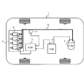
- FIG. 1 is a system configuration diagram of a fuel supply device for an internal combustion engine according to an embodiment of the present invention. It is a figure which shows the structural example of the electric fuel pump in FIG. It is a figure for demonstrating the fuel pressure in each driving
- FIG. 1 is a system configuration diagram of a fuel supply device for an internal combustion engine according to an embodiment of the present invention.
- This system includes an ECM (Engine control module) 3, an FCM (Fuel control module) 4, an electric fuel pump (FPM) 5, a fuel injection valve (injector) 6, a fuel pressure sensor 7, a fuel pipe 8, and the like. Consists of including.
- the ECM 3 is a main control device that controls the engine 2 of the automobile (vehicle) 1.
- the ECM 3 is a microcomputer that executes various arithmetic processes, a ROM that stores various control arithmetic programs and data, a RAM that stores numerical values and flags of arithmetic processes, and an EEPROM that stores the results of arithmetic processes.
- An A / D converter that converts the analog signal into a digital signal, an input / output interface circuit that inputs and outputs various digital signals, and the like. These devices are connected to each other via a bus line to exchange data.
- the output of the fuel pressure sensor 7 for detecting the fuel pressure in the fuel pipe 8 is supplied to the ECM 3 and a control signal for setting the electric fuel pump 5 to the target fuel pressure is output to the FCM 4. Further, the fuel injection is controlled by outputting a control signal for setting the injection timing to the fuel injection valve 6.
- the FCM 4 continuously controls the rotational speed of the electric fuel pump 5 to change the amount of fuel supplied. Then, fuel is supplied from the electric fuel pump 5 to the fuel injection valve 6 through the fuel pipe 8, and the fuel is injected from the fuel injection valve 6 into the cylinders of the cylinders of the engine 2 or into the intake pipe. At this time, the pressure of the fuel pumped from the electric fuel pump 5 toward the fuel injection valve 6 is variably controlled by the FCM 4 according to the operating state of the engine 2.
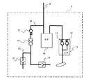
- FIG. 2 shows a configuration example of the electric fuel pump 5 in FIG.
- the electric fuel pump 5 is rotationally driven by a motor and is disposed in the fuel tank.
- the electric fuel pump 5 includes a fuel pump (F / P) 11, a relief valve 12, a check valve 13, a jet pump 14, a transfer jet pump 15, a fuel filter (F / F) 16, a pressure regulator 17, an orifice 18, and the like. It has.
- One end of the fuel pipe 8 is connected to the discharge port of the electric fuel pump 5.
- a fuel filter 16 is interposed in the fuel pipe 8, and fuel is filtered by the fuel filter 16.
- a fuel return pipe 19 is branched from the fuel pipe 8 where the fuel filter 16 is interposed, and a pressure regulator 17, an orifice 18 and a jet pump 14 are interposed in order from the upstream side. The other end of the fuel return pipe 19 is opened in the fuel tank.
- One end of a fuel transfer pipe 20 is connected to the jet pump 14, and a transfer jet pump 15 is interposed in the fuel transfer pipe 20. The other end of the fuel transfer pipe 20 is opened in the fuel tank.
- This example is a configuration in the case where the fuel tank is used in a so-called bowl-shaped configuration in which a convex portion that divides the bottom side of the internal space into two regions is formed protruding from the bottom surface, and the fuel return pipe 19 is in the first region.
- the fuel transfer pipe is configured to open in the second region.
- the jet pump 15 applies a negative pressure to the fuel transfer pipe 20 by the flow of the fuel returned to the first area side via the fuel return pipe 19, and causes the fuel in the second area where the fuel transfer pipe 20 is opened to flow. , Transferred to the first region side. Therefore, when the fuel tank is not of the saddle shape, the transfer jet pump 15 and the fuel transfer pipe 20 can be omitted.
- the fuel pump 11 is opened when the pressure on the discharge side exceeds the maximum allowable pressure, and a mechanical relief valve 12 that relieves the fuel into the fuel tank, and from the fuel pump 11 to the fuel injection valve 6 side.
- a mechanical check valve 13 is provided in parallel, which allows only the flow of the directed fuel and prevents the reverse flow of fuel from the fuel injection valve 6 side toward the fuel pump 11. Note that the relief valve 12 and the check valve 13 may be disposed downstream of the fuel pump 11.
- the pressure regulator 17 is generally composed of a valve body that opens and closes the fuel return pipe 19 and an elastic member that presses the valve body toward the valve seat on the upstream side of the fuel return pipe 19. This compensates for the minimum pressure of the supplied fuel pressure. That is, the pressure regulator 17 is closed when the fuel pressure (injection pressure, discharge side pressure of the fuel pump 11) supplied to the fuel injection valve 6 is equal to or lower than the minimum pressure, and is opened when the pressure is higher than the minimum pressure. It has a configuration.
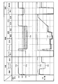
- FIG. 3 shows the fuel pressure and the discharge amount of the fuel pump in each operating state of the engine 2 in the fuel supply device for the internal combustion engine described above, the fuel pressure in the fixed fuel pressure and the conventional variable fuel pressure system, and the discharge amount of the electric fuel pump. Is shown in comparison.
- broken lines 31a and 31b indicate the fixed fuel pressure
- solid lines 32a and 32b indicate the fuel pressure and the discharge amount of the fuel pump in the variable fuel pressure system, respectively.
- the fuel pressure becomes a constant value (about 350 kPa) when the engine is started.
- the discharge flow rate of the fuel pump is a constant value when the engine is started, and becomes zero when the engine is stopped.
- the fuel pressure is increased to about 650 kPa when the engine is started, and the fuel pressure is maintained until the engine is stopped (starting, first idle, steady).
- starting first idle, steady
- the fuel pressure is reduced to about 200 kPa to reduce the fuel density.
- the fuel pressure is temporarily increased to about 650 kPa, but the fuel pressure is decreased to about 300 kPa after a predetermined time.
- a fuel pressure of about 300 kPa is maintained.
- fuel consumption is reduced by reducing the fuel pressure.
- the fuel pressure is increased to about 650 kPa, thereby increasing the charging efficiency and improving knock resistance.
- the fuel pressure is reduced to about 300 kPa, and when the engine is restarted, the fuel pressure is increased to about 650 kPa.
- the discharge amount of the fuel pump increases when the engine is started when the engine is cold, decreases at the first idle, and becomes an intermediate level between the start and the first idle in the steady state.
- the discharge amount becomes substantially zero, the discharge amount is temporarily increased at the initial stage of the idle state, and the discharge amount is decreased after a predetermined time.
- the discharge amount is set to a low value suitable for each of an idle state, a steady state, and a transient state (deceleration and acceleration).
- WOT Wide Open Throttle
- the discharge amount is increased to the maximum value.
- the discharge amount becomes zero, and when the engine is restarted, the discharge amount is increased to a discharge amount lower than the fixed fuel pressure.
- the fuel consumption can be reduced and the tank fuel temperature can be lowered.
- the idle state, the steady state, and the transient state after engine warm-up are shown in the conventional variable fuel pressure system described above.
- the fuel pressure is lowered further than the normal variable fuel pressure system.
- the fuel consumption is reduced by reducing the power consumption of the fuel pump 11.
- the discharge amount of the fuel pump 11 is further lower in the idle state, the steady state, and the transient state (deceleration and acceleration) after engine warm-up, as shown by the hatched region 33b.
- vapor may be generated when the engine 2 is stopped.
- FIG. 4 is a flowchart showing a control operation when restarting from an idle stop
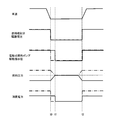
- FIG. 5 is a timing chart for explaining the control operation of FIG.
- step S1 it is determined whether or not the engine 2 is restarted after idling stop (engine warm-up state) from the oil temperature or water temperature. If the engine is restarted, the target fuel pressure and the actual fuel pressure are determined. Originally, the drive instruction value of the electric fuel pump 5 is determined and set to the first fuel pressure (low fuel pressure mode) (step S2).
- This first fuel pressure is lower than 220 kPa at which the fuel vaporizes at the warm-up completion temperature, for example, about 150 kPa. After the warm-up is completed, it is confirmed by experiment that the combustion does not deteriorate even if the fuel pressure is lowered to about 150 kPa. Yes.
- step S3 it is determined whether or not the engine is in an idle stop state. If it is determined that the engine is in the idle stop state, the ECM 3 stops the drive of the fuel injection valve 6 based on the target fuel pressure and the actual fuel pressure, and then the FCM 4 delays the drive stop of the electric fuel pump 5, The fuel pressure in the fuel pipe 8 is increased by driving for a time and set to the second fuel pressure (high fuel pressure mode) (step S4). The drive stop of the electric fuel pump 6 continues after the operation of the fuel injection valve 6 stops until the actual fuel pressure in the fuel pipe 8 reaches a predetermined pressure.
- the second fuel pressure is higher than 220 kPa and is a normal pressure, for example, about 250 kPa. If it is determined in step S3 that the engine is not in the idle stop state, the ECM 3 determines a drive instruction value for the electric fuel pump 5 based on the target fuel pressure and the actual fuel pressure, and the FCM 4 determines the first fuel pressure ( Low fuel pressure mode) is set (step S5). This first fuel pressure is lower than 220 kPa, for example, about 150 kPa.
- the drive voltage of the fuel injection valve 6 becomes “0V” at time t0, and time t2
- the predetermined voltage is the same as that of the conventional variable fuel pressure system indicated by the one-dot chain line and the fuel supply device for the internal combustion engine of the present invention indicated by the solid line.
- the drive instruction value of the electric fuel pump 5 becomes zero at time t0 in the conventional variable fuel pressure system, whereas the fuel supply device of the internal combustion engine of the present invention has zero at time t1 when a predetermined time has elapsed from time t0. become.
- the fuel injection valve 6 and the electric fuel pump 5 are stopped at time t0, whereas in the fuel supply device for the internal combustion engine of the present invention, the electric fuel pump 5 is stopped at time t0. Then, the electronic fuel pump 5 is stopped at time t1 delayed by a predetermined time.
- the fuel pressure starts to decrease at time t0, decreases to the normal pressure, and then increases again at time t2.
- the pressure starts increasing at time t0, increases to normal pressure, and then decreases again at time t2. Therefore, the power consumption by the fuel pump 11 (electric fuel pump 5) is higher in the present invention between the times t0 and t1, but is lower in the present invention before the time t0 and after the time t1, and the low power consumption. Can be achieved.
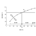
- FIG. 6 shows the relationship between the fuel pressure and the boiling point of the fuel (vapor generation temperature with respect to the fuel pressure). Assuming that the maximum value of the fuel temperature is 70 ° C. in the idling stop state after the engine is warmed up, the gasoline, which is fuel, is gas in the region above the solid line 34 and liquid in the region below.
- the fuel pressure is lowered in steady operation by driving control of the electric fuel pump 5.
- region of the 2nd, 3rd fuel pressure whose fuel pressure is 220 kPa or more is the fuel pressure of the conventional steady operation.
- the fuel does not become gas if the fuel temperature is 70 ° C. or lower.
- the boiling point decreases as the fuel pressure decreases, and vaporization easily occurs.
- the fuel injection valve 6 when the engine 2 is in the warm-up state, the fuel injection valve 6 is fueled at the first fuel pressure (for example, 150 kPa) lower than the predetermined pressure (about 220 kPa) at which the fuel is vaporized at the warm-up completion temperature. Supply. Further, when the engine 2 is stopped in the warm-up state, after the fuel injection by the fuel injection valve 6 is stopped, the electric fuel pump 5 is continuously driven for a predetermined period, and the inside of the fuel pipe 8 is maintained at the predetermined pressure. To a higher second fuel pressure (for example, 250 kPa) for preventing vapor.
- the first fuel pressure for example, 150 kPa
- the predetermined pressure about 220 kPa
- the fuel pressure during steady operation after engine warm-up is controlled at a fuel pressure lower than the fuel pressure in the conventional variable fuel pressure system (no vapor is generated). Further, when the engine 2 is restarted in a warm-up state, the electric fuel pump 5 is driven so that the inside of the fuel pipe 8 becomes the second fuel pressure. Further, the fuel pressure is increased to the third fuel pressure (for example, about 650 kPa) in the heat resistant temperature condition higher than the warm-up temperature, that is, the WOT state.
- the third fuel pressure for example, about 650 kPa
- the electric fuel pump 5 when the driving of the fuel injection valve 6 is stopped, the electric fuel pump 5 is driven for a predetermined time to delay the driving of the electric fuel pump 5. Accordingly, since the fuel pipe 8 is plugged with the fuel injection valve 6, the pressure in the fuel pipe 8 can be increased to a fuel pressure at which no vapor is generated. Therefore, while lowering the fuel pressure after engine warm-up and improving fuel economy, during the idle stop period, after injecting fuel from the fuel injection valve, the electric fuel pump is stopped to obtain fuel pressure for vapor countermeasures. Raising the vapor can suppress the generation of vapor.
- SYMBOLS 1 ... Automobile (vehicle), 2 ... Engine (internal combustion engine), 3 ... ECM, 4 ... FCM, 5 ... Electric fuel pump (FPM), 6 ... Fuel injection valve (injector), 7 ... Fuel pressure sensor, 8 ... Fuel Piping
Landscapes
- Engineering & Computer Science (AREA)
- Chemical & Material Sciences (AREA)
- Combustion & Propulsion (AREA)
- Mechanical Engineering (AREA)
- General Engineering & Computer Science (AREA)
- Fuel-Injection Apparatus (AREA)
- Electrical Control Of Air Or Fuel Supplied To Internal-Combustion Engine (AREA)
- Control Of Vehicle Engines Or Engines For Specific Uses (AREA)
Abstract
本発明は、内燃機関の運転状態に応じて燃料ポンプの吐出流量及び燃料噴射圧力を制御する内燃機関の燃料供給装置及び燃料供給方法に関する。機関暖機後の燃圧を低くして燃費の向上を図りつつ、アイドルストップ期間中にベーパーの発生を抑制できる内燃機関の燃料供給装置及び燃料供給方法を提供する。電動式燃料ポンプから燃料噴射弁に向けて圧送される燃料の圧力を、内燃機関の作動状態に応じて可変制御する内燃機関の燃料供給装置において、内燃機関が暖機状態で停止させるときに、燃料噴射弁による燃料噴射を停止した後、所定期間、電動式燃料ポンプの駆動を継続し、燃料配管内をベーパー対策用の燃料圧力に上昇させる。これによって、機関暖機後の燃料圧力を低くしても、アイドルストップ期間中にベーパーの発生を抑制できる。
Description
本発明は、内燃機関の運転状態に応じて燃料ポンプの吐出流量及び燃料噴射圧力を制御する内燃機関の燃料供給装置及び燃料供給方法に関する。
内燃機関の運転状態に応じて燃料ポンプの吐出流量及び燃料噴射圧力を制御する、いわゆる可変燃圧システムでは、冷機始動時に燃圧(燃料圧力)を高くして噴射燃料を微粒子化することでHC(Hydrocarbon)を低減し、機関暖機後には燃圧を低くして燃料ポンプの消費電力を削減することで燃費を稼いでいる。
また、例えば特許文献1には、エンジンの再始動時に燃圧がある程度高い状態から燃料噴射制御を開始させことで、噴霧状態を良好にして排気エミッションを低減するエンジン制御装置が開示されている。再始動時の燃圧を高めた分、燃料を余計に噴く必要がなくなるので燃費も向上できる。
また、例えば特許文献1には、エンジンの再始動時に燃圧がある程度高い状態から燃料噴射制御を開始させことで、噴霧状態を良好にして排気エミッションを低減するエンジン制御装置が開示されている。再始動時の燃圧を高めた分、燃料を余計に噴く必要がなくなるので燃費も向上できる。
ところで、可変燃圧システムにあっては、機関暖機後の燃圧をより低くすることで燃費の向上が図れる。しかし、燃圧を下げすぎるとアイドルストップ中にベーパーが発生する虞があるため、燃圧を下げるのには限界がある。
一方、特許文献1のように、エンジン停止後の燃圧を高めることで、ベーパーの発生を抑制できる。しかしながら、特許文献1は、再始動時に燃圧が低い状態から燃料噴射を再開することによる排気エミッションの悪化を課題としている。このため、機関作動中の燃圧や燃費の向上については考慮されておらず、まだ改良の余地がある。
一方、特許文献1のように、エンジン停止後の燃圧を高めることで、ベーパーの発生を抑制できる。しかしながら、特許文献1は、再始動時に燃圧が低い状態から燃料噴射を再開することによる排気エミッションの悪化を課題としている。このため、機関作動中の燃圧や燃費の向上については考慮されておらず、まだ改良の余地がある。
本発明は上記のような事情に鑑みてなされたもので、その目的とするところは、機関暖機後の燃圧を低くして燃費の向上を図りつつ、アイドルストップ期間中にベーパーの発生を抑制できる内燃機関の燃料供給装置及び燃料供給方法を提供することにある。
本発明の内燃機関の燃料供給装置は、電動式燃料ポンプから燃料噴射弁に向けて圧送される燃料の圧力を、内燃機関の作動状態に応じて可変制御する内燃機関の燃料供給装置において、前記内燃機関を暖機状態で停止させるときに、前記燃料噴射弁による燃料噴射を停止した後、所定期間、前記電動式燃料ポンプの駆動を継続し、燃料配管内をベーパー対策用の燃料圧力に上昇させる、ことを特徴とする。
また、本発明の内燃機関の燃料供給方法は、電動式燃料ポンプから燃料噴射弁に向けて圧送される燃料の圧力を、内燃機関の作動状態に応じて可変制御する内燃機関の燃料供給方法において、前記内燃機関が暖機状態では、暖機完了温度で燃料が気化する所定圧力よりも低い第1燃料圧力で前記燃料噴射弁に燃料を供給し、前記内燃機関を暖機状態で停止させるときは、前記燃料噴射弁による燃料噴射を停止させた後、所定期間、前記電動式燃料ポンプの駆動を継続し、燃料配管内を前記所定圧力よりも高いベーパー対策用の第2燃料圧力に上昇させる、ことを特徴とする。
また、本発明の内燃機関の燃料供給方法は、電動式燃料ポンプから燃料噴射弁に向けて圧送される燃料の圧力を、内燃機関の作動状態に応じて可変制御する内燃機関の燃料供給方法において、前記内燃機関が暖機状態では、暖機完了温度で燃料が気化する所定圧力よりも低い第1燃料圧力で前記燃料噴射弁に燃料を供給し、前記内燃機関を暖機状態で停止させるときは、前記燃料噴射弁による燃料噴射を停止させた後、所定期間、前記電動式燃料ポンプの駆動を継続し、燃料配管内を前記所定圧力よりも高いベーパー対策用の第2燃料圧力に上昇させる、ことを特徴とする。
本発明によれば、機関暖機後の燃料圧力を低くして燃費の向上を図りつつ、アイドルストップ期間中に、燃料噴射弁による燃料噴射を停止した後、所定期間、電動式燃料ポンプの駆動を継続して燃料配管内をベーパー対策用の燃料圧力に上昇させることで、ベーパーの発生を抑制できる。
以下、本発明の実施形態について図面を参照して説明する。
図1は、本発明の実施形態に係る内燃機関の燃料供給装置のシステム構成図である。このシステムは、ECM(Engine control module)3、FCM(Fuel control module)4、電動式燃料ポンプ(FPM:Fuel Pomp module)5、燃料噴射弁(インジェクタ)6、燃圧センサ7及び燃料配管8等を含んで構成される。
図1は、本発明の実施形態に係る内燃機関の燃料供給装置のシステム構成図である。このシステムは、ECM(Engine control module)3、FCM(Fuel control module)4、電動式燃料ポンプ(FPM:Fuel Pomp module)5、燃料噴射弁(インジェクタ)6、燃圧センサ7及び燃料配管8等を含んで構成される。
ECM3は、自動車(車両)1のエンジン2を制御する主制御装置である。ECM3は、各種の演算処理を実行するマイクロコンピュータ、各種の制御演算プログラムやデータを格納したROM、演算過程の数値やフラグが格納されるRAM、演算処理の結果などが格納されるEEPROM、入力されたアナログ信号をデジタル信号に変換するA/Dコンバータ、及び各種のデジタル信号が入出力される入出力インタフェース回路等を備える。これら各機器は、それぞれバスラインで相互に接続されてデータの授受を行う。
ECM3には、燃料配管8内の燃圧を検出する燃圧センサ7の出力が供給され、FCM4に電動式燃料ポンプ5を目標燃圧に設定するための制御信号を出力する。また、燃料噴射弁6に噴射タイミングを設定するための制御信号を出力して燃料噴射を制御する。FCM4は、電動式燃料ポンプ5の回転数を無段階制御し、供給燃料量を変更する。そして、電動式燃料ポンプ5から燃料配管8を介して燃料噴射弁6に燃料を供給し、燃料噴射弁6からエンジン2の各気筒のシリンダ内、あるいは吸気配管内に燃料を噴射する。この際、電動式燃料ポンプ5から燃料噴射弁6に向けて圧送される燃料の圧力を、FCM4によりエンジン2の運転状態に応じて可変制御する。
図2は、上記図1における電動式燃料ポンプ5の構成例を示している。電動式燃料ポンプ5は、モータで回転駆動され、燃料タンク内に配置される。電動式燃料ポンプ5は、フューエルポンプ(F/P)11、リリーフバルブ12、チェックバルブ13、ジェットポンプ14、移送用ジェットポンプ15、フューエルフィルタ(F/F)16、プレッシャーレギュレータ17及びオリフィス18等を備えている。
電動式燃料ポンプ5の吐出口には燃料配管8の一端が接続される。燃料配管8には、フューエルフィルタ16が介装され、このフューエルフィルタ16で燃料がろ過される。フューエルフィルタ16が介装される燃料配管8から分岐して燃料戻し配管19が延設され、上流側から順に、プレッシャーレギュレータ17、オリフィス18及びジェットポンプ14が介装されている。燃料戻し配管19の他端は、燃料タンク内に開口される。ジェットポンプ14には、燃料移送配管20の一端が接続され、該燃料移送配管20には移送用ジェットポンプ15が介装される。この燃料移送配管20の他端は、燃料タンク内に開口される。
本例は、燃料タンクが、内部空間の底側を2領域に仕切る凸部が底面から突出形成されたいわゆる鞍型形状のものに用いる場合の構成であり、燃料戻し配管19は第1領域内に開口し、燃料移送配管は第2領域内に開口するように構成している。ジェットポンプ15は、燃料戻し配管19を介して第1領域側に戻される燃料の流れによって、燃料移送配管20内に負圧を作用させ、燃料移送配管20が開口する第2領域内の燃料を、第1領域側に移送させる。
従って、燃料タンクが鞍型形状でない場合には、移送用ジェットポンプ15及び燃料移送配管20は省略することができる。
従って、燃料タンクが鞍型形状でない場合には、移送用ジェットポンプ15及び燃料移送配管20は省略することができる。
フューエルポンプ11内には、吐出側の圧力が最大許容圧を超えたときに開弁し、燃料を燃料タンク内にリリーフする機械式のリリーフバルブ12と、フューエルポンプ11から燃料噴射弁6側に向けた燃料の流れのみを許容し、燃料噴射弁6側からフューエルポンプ11に向かう燃料の逆流を阻止する機械式のチェックバルブ13とが並列に設けられている。なお、リリーフバルブ12及びチェックバルブ13は、フューエルポンプ11の下流側に介装させる構成であってもよい。
プレッシャーレギュレータ17は、燃料戻し配管19を開閉する弁体と、該弁体を燃料戻し配管19の上流側の弁座に向けて押圧する弾性部材とから概略構成されており、燃料噴射弁6に供給される燃料圧力の最小圧力を補償するものである。すなわち、プレッシャーレギュレータ17は、燃料噴射弁6に供給される燃料圧力(噴射圧、フューエルポンプ11の吐出側圧)が上記最小圧力以下であるときは閉弁し、最小圧力よりも高くなると開弁する構成となっている。
図3は、上述した内燃機関の燃料供給装置における、エンジン2の各運転状態での燃圧及び燃料ポンプの吐出量と、固定燃圧及び従来の可変燃圧システムにおける燃圧と電動式燃料ポンプの吐出量とを比較して示している。図3において、破線31a,31bは固定燃圧の場合、実線32a,32bは可変燃圧システムの場合の燃圧及び燃料ポンプの吐出量をそれぞれ示している。
固定燃圧では、破線31aで示すように、エンジンが始動すると燃圧は一定値(350kPa程度)となる。また、破線31bで示すように、フューエルポンプの吐出流量は、エンジンが始動すると一定値であり、エンジンの停止時にはゼロになる。
固定燃圧では、破線31aで示すように、エンジンが始動すると燃圧は一定値(350kPa程度)となる。また、破線31bで示すように、フューエルポンプの吐出流量は、エンジンが始動すると一定値であり、エンジンの停止時にはゼロになる。
従来の可変燃圧システムでは、実線32aで示すように、機関冷機時にはエンジンが始動すると燃圧を650kPa程度まで上昇させ、エンジンが停止するまで燃圧を維持する(始動、ファーストアイドル、定常)ことで、燃圧の高圧化により燃料を微粒子化し、HCを削減する。一方、機関暖機後にエンジンが停止すると、燃圧を200kPa程度まで低下させて燃料密度を低減する。アイドル状態の初期では、一時的に燃圧を650kPa程度まで上昇させるが、所定時間後に300kPa程度まで燃圧を低下させる。そして、定常状態、過渡状態(減速、加速)では、300kPa程度の燃圧を維持する。このように、燃圧を低圧化することにより燃費を低減する。
エンジンに高負荷がかかるWOT(Wide Open Throttle)状態では、燃圧を650kPa程度まで上昇させることで、充填効率を高めると共にノック耐性を改善する。耐熱状態でエンジンを停止させた場合には、300kPa程度まで燃圧を低下させ、エンジンが再始動すると燃圧を650kPa程度まで上昇させる。このように、高圧化することにより、ベーパーを除去し且つ始動性を確保する。
フューエルポンプの吐出量は、機関冷機時にエンジンが始動すると多くなり、ファーストアイドルでは低下し、定常状態では始動とファーストアイドルの中間レベルとなる。そして、機関暖機後にエンジンが停止すると、吐出量はほぼゼロとなり、アイドル状態の初期で一時的に吐出量を上昇させ、所定時間後に吐出量を低下させる。吐出量は、アイドル、定常状態、過渡状態(減速、加速)で、それぞれに適した低い値とする。WOT(Wide Open Throttle)状態では、吐出量を最大値まで上昇させる。更に、耐熱状態でエンジンを停止させた場合には、吐出量はゼロとなり、エンジンが再始動すると固定燃圧よりも低い吐出量まで上昇させる。このように、機関暖機状態において、フューエルポンプの吐出流量を最適化することで、燃費を低減すると共にタンク燃温を低下させることができる。
本発明の実施形態に係る内燃機関の燃料供給装置では、上述した従来の可変燃圧システムに対して、斜線を付した領域33aに示すように、機関暖機後のアイドル状態、定常状態、過渡状態(減速、加速)において、通常の可変燃圧システムより更に燃圧を下げている。これにより、フューエルポンプ11の消費電力を下げることで低燃費化を図っている。また、フューエルポンプ11の吐出量は、斜線を付した領域33bに示すように、機関暖機後のアイドル状態、定常状態、過渡状態(減速、加速)においてより更に低くなっている。この燃圧では、エンジン2が停止するとベーパーが発生する可能性がある。
次に、上述した燃料供給装置及び燃料供給方法において、アイドルストップ期間中の制御動作について詳しく説明する。図4は、アイドルストップから再始動する際の制御動作を示すフローチャート、図5は、図4の制御動作について説明するためのタイミングチャートである。まず、例えば油温や水温などからアイドルストップ後(機関暖機状態)でのエンジン2の再始動か否かを判定し(ステップS1)、再始動であれば目標燃圧と実際の燃圧の値を元に、電動式燃料ポンプ5の駆動指示値を決定し、第1燃圧(低燃圧モード)に設定する(ステップS2)。この第1燃圧は、暖機完了温度で燃料が気化する220kPaよりも低く、例えば150kPa程度であり、暖機完了後には150kPa程度まで燃圧を下げても燃焼が悪化しないことを実験により確認している。
一方、ステップS1で再始動ではないと判定された場合には、アイドルストップ状態か否かを判定する(ステップS3)。アイドルストップ状態であると判定されると、ECM3により目標燃圧と実際の燃圧の値を元に燃料噴射弁6の駆動を停止させた後、FCM4で電動式燃料ポンプ5の駆動停止を遅らせ、所定時間駆動させて燃料配管8内の燃圧を上げて第2燃圧(高燃圧モード)に設定する(ステップS4)。電動式燃料ポンプ6の駆動停止は、燃料噴射弁6の作動停止後、燃料配管8内の実際の燃圧が所定圧力となるまで継続する。上記第2燃圧は、220kPaよりも高く、通常圧力、例えば250kPa程度である。
また、ステップS3でアイドルストップ状態ではないと判定された場合には、ECM3により目標燃圧と実際の燃圧の値を元に電動式燃料ポンプ5の駆動指示値を決定し、FCM4で第1燃圧(低燃圧モード)に設定する(ステップS5)。この第1燃圧は、220kPaよりも低く、例えば150kPa程度である。
また、ステップS3でアイドルストップ状態ではないと判定された場合には、ECM3により目標燃圧と実際の燃圧の値を元に電動式燃料ポンプ5の駆動指示値を決定し、FCM4で第1燃圧(低燃圧モード)に設定する(ステップS5)。この第1燃圧は、220kPaよりも低く、例えば150kPa程度である。
図5のタイミングチャートに示すように、車速が低下して時刻t0にアイドルストップし、時刻t2に再始動する場合には、時刻t0に燃料噴射弁6の駆動電圧が「0V」となり、時刻t2に所定電圧となる点は、一点鎖線で示す従来の可変燃圧システムと実線で示す本発明の内燃機関の燃料供給装置で同様である。しかし、電動式燃料ポンプ5の駆動指示値は、従来の可変燃圧システムでは時刻t0にゼロになるのに対し、本発明の内燃機関の燃料供給装置は時刻t0から所定時間経過した時刻t1にゼロになる。
すなわち、従来の可変燃圧システムでは時刻t0に燃料噴射弁6と電動式燃料ポンプ5を停止させていたのに対し、本発明の内燃機関の燃料供給装置では時刻t0に電動式燃料ポンプ5を停止させた後、所定時間遅れた時刻t1に電子式燃料ポンプ5を停止させている。
これによって、燃圧は、従来の可変燃圧システムでは時刻t0に低下を始め、通常の圧力に低下した後、時刻t2に再び上昇する。これに対し、本発明の場合には、時刻t0に上昇を始め、通常の圧力に上昇した後、時刻t2に再び低下することになる。従って、フューエルポンプ11(電動式燃料ポンプ5)による消費電力は、時刻t0~t1間では本発明の方が高いものの、時刻t0以前及び時刻t1以降は本発明の方が低くなり、低消費電力化が図れる。
これによって、燃圧は、従来の可変燃圧システムでは時刻t0に低下を始め、通常の圧力に低下した後、時刻t2に再び上昇する。これに対し、本発明の場合には、時刻t0に上昇を始め、通常の圧力に上昇した後、時刻t2に再び低下することになる。従って、フューエルポンプ11(電動式燃料ポンプ5)による消費電力は、時刻t0~t1間では本発明の方が高いものの、時刻t0以前及び時刻t1以降は本発明の方が低くなり、低消費電力化が図れる。
次に、上述したように、機関暖機後のアイドル状態、定常状態、過渡状態(減速、加速)において燃圧を下げることにより発生しやすくなるベーパーの抑制動作について、図6により詳しく説明する。
図6は、燃圧と燃料の沸点との関係(燃圧に対するベーパーの発生温度)を示している。機関暖機後のアイドルストップ状態において、燃温の最大値が70℃と仮定すると、燃料であるガソリンは実線34よりも上の領域が気体、下の領域が液体となる。
図6は、燃圧と燃料の沸点との関係(燃圧に対するベーパーの発生温度)を示している。機関暖機後のアイドルストップ状態において、燃温の最大値が70℃と仮定すると、燃料であるガソリンは実線34よりも上の領域が気体、下の領域が液体となる。
燃圧が220kPa以下の第1燃圧の領域では、定常運転での低燃圧化を電動式燃料ポンプ5の駆動制御で行う。また、燃圧が220kPa以上の第2、第3燃圧の領域は、従来の定常運転の燃圧である。これらの領域を比較すれば明らかなように、燃圧が第2、第3燃圧領域では、燃温が70℃以下であれば燃料が気体になることはない。これに対し、燃圧が第1燃圧領域では、燃圧が下がるに従って沸点が下がり、気化しやすくなる。
上述したように、本発明では、エンジン2が暖機状態では、暖機完了温度で燃料が気化する所定圧力(220kPa程度)よりも低い第1燃料圧力(例えば150kPa)で燃料噴射弁6に燃料を供給する。更に、暖機状態でエンジン2を停止させるときは、燃料噴射弁6による燃料噴射を停止させた後、所定期間、電動式燃料ポンプ5の駆動を継続し、燃料配管8内を上記所定圧力よりも高いベーパー対策用の第2燃料圧力(例えば250kPa)に上昇させる。従って、機関暖機後の定常運転時の燃圧は、従来の可変燃圧システムにおける燃圧(ベーパーが発生しない)よりも低い燃圧で制御することになる。
また、エンジン2が暖機状態で再始動するときは、燃料配管8内が第2燃料圧力となるように電動式燃料ポンプ5を駆動する。更に、エンジン2が暖機温度よりも高い耐熱温度条件、すなわちWOT状態では、第3燃料圧力(例えば650kPa程度)まで燃料圧力を上昇させる。
また、エンジン2が暖機状態で再始動するときは、燃料配管8内が第2燃料圧力となるように電動式燃料ポンプ5を駆動する。更に、エンジン2が暖機温度よりも高い耐熱温度条件、すなわちWOT状態では、第3燃料圧力(例えば650kPa程度)まで燃料圧力を上昇させる。
このような構成並びに制御方法では、燃料噴射弁6の駆動を停止させたときに、電動式燃料ポンプ5を所定時間駆動して電動式燃料ポンプ5の駆動を止めるのを遅らせる。これによって、燃料配管8に燃料噴射弁6で栓がされているので、燃料配管8内の圧力を上げて、ベーパーが発生しない燃圧まで上げることができる。従って、機関暖機後の燃圧を低くして燃費の向上を図りつつ、アイドルストップ期間中に、燃料噴射弁から燃料を噴射した後に電動式燃料ポンプを停止させて、ベーパー対策用の燃料圧力に上昇させることでベーパーの発生を抑制できる。
1…自動車(車両)、2…エンジン(内燃機関)、3…ECM、4…FCM、5…電動式燃料ポンプ(FPM)、6…燃料噴射弁(インジェクタ)、7…燃圧センサ、8…燃料配管
Claims (15)
- 電動式燃料ポンプから燃料噴射弁に向けて圧送される燃料の圧力を、内燃機関の作動状態に応じて可変制御する内燃機関の燃料供給装置において、
前記内燃機関を暖機状態で停止させるときに、前記燃料噴射弁による燃料噴射を停止した後、所定期間、前記電動式燃料ポンプの駆動を継続し、燃料配管内をベーパー対策用の燃料圧力に上昇させる、ことを特徴とする内燃機関の燃料供給装置。 - 前記内燃機関が暖機状態で機関作動するときに、電動式燃料ポンプから燃料噴射弁に、機関暖機完了温度で燃料が気化する圧力よりも低い燃料圧力で燃料を供給する、ことを特徴とする請求項1に記載の内燃機関の燃料供給装置。
- 前記機関暖機完了温度で燃料が気化するよりも低い燃料圧力は、前記ベーパー対策用の燃料圧力より低い、ことを特徴とする請求項2に記載の内燃機関の燃料供給装置。
- 前記内燃機関を暖機状態で再始動するときに、前記電動式燃料ポンプを、前記燃料配管内が前記ベーパー対策用の燃料圧力となるように駆動する、ことを特徴とする請求項1に記載の内燃機関の燃料供給装置。
- 前記内燃機関が暖機温度よりも高い耐熱温度条件のときに、前記電動式燃料ポンプを、前記燃料配管内が前記ベーパー対策用の燃料圧力よりも高い燃料圧力となるように駆動する、ことを特徴とする請求項1に記載の内燃機関の燃料供給装置。
- 前記電動式燃料ポンプの駆動の継続は、前記燃料噴射弁の作動停止後、前記燃料配管内の実際の燃料圧力が前記ベーパー対策用の燃料圧力となるまで実行する、ことを特徴とする請求項1に記載の内燃機関の燃料供給装置。
- 前記電動式燃料ポンプの駆動の継続は、前記燃料噴射弁の作動停止後、前記燃料配管内の実際の燃料圧力が前記ベーパー対策用の燃料圧力よりも高い燃料圧力となるまで実行する、ことを特徴とする請求項5に記載の内燃機関の燃料供給装置。
- 前記内燃機関の暖機状態の停止は、アイドルストップを含む、ことを特徴とする請求項1に記載の内燃機関の燃料供給装置。
- 電動式燃料ポンプから燃料噴射弁に向けて圧送される燃料の圧力を、内燃機関の作動状態に応じて可変制御する内燃機関の燃料供給方法において、
前記内燃機関が暖機状態では、暖機完了温度で燃料が気化する所定圧力よりも低い第1燃料圧力で前記燃料噴射弁に燃料を供給し、
前記内燃機関を暖機状態で停止させるときは、前記燃料噴射弁による燃料噴射を停止させた後、所定期間、前記電動式燃料ポンプの駆動を継続し、燃料配管内を前記所定圧力よりも高いベーパー対策用の第2燃料圧力に上昇させる、ことを特徴とする内燃機関の燃料供給方法。 - 前記第1燃料圧力は、前記第2燃料圧力より低い、ことを特徴とする請求項9に記載の内燃機関の燃料供給方法。
- 更に、前記内燃機関を暖機状態で再始動するときは、前記電動式燃料ポンプを、前記燃料配管内が前記第2燃料圧力となるように駆動する、ことを特徴とする請求項9に記載の内燃機関の燃料供給方法。
- 更に、前記内燃機関が暖機温度よりも高い耐熱温度条件のときに、前記電動式燃料ポンプを、前記燃料配管内が前記第2燃料圧力よりも高い第3燃料圧力となるように駆動する、ことを特徴とする請求項9に記載の内燃機関の燃料供給方法。
- 前記燃料噴射弁の作動停止後、前記電動式燃料ポンプの駆動を、前記燃料配管内の実際の燃料圧力が前記第2燃料圧力となるまで継続する、ことを特徴とする請求項9に記載の内燃機関の燃料供給方法。
- 前記燃料噴射弁の作動停止後、前記電動式燃料ポンプの駆動を、前記燃料配管内の実際の燃料圧力が前記第3燃料圧力よりも低い所定圧力となるまで継続する、ことを特徴とする請求項12に記載の内燃機関の燃料供給方法。
- 前記内燃機関の暖機状態の停止は、アイドルストップを含む、ことを特徴とする請求項9に記載の内燃機関の燃料供給方法。
Applications Claiming Priority (2)
| Application Number | Priority Date | Filing Date | Title |
|---|---|---|---|
| JP2014-051659 | 2014-03-14 | ||
| JP2014051659A JP6302710B2 (ja) | 2014-03-14 | 2014-03-14 | 内燃機関の燃料供給装置及び燃料供給方法 |
Publications (1)
| Publication Number | Publication Date |
|---|---|
| WO2015136745A1 true WO2015136745A1 (ja) | 2015-09-17 |
Family
ID=54071213
Family Applications (1)
| Application Number | Title | Priority Date | Filing Date |
|---|---|---|---|
| PCT/JP2014/074444 Ceased WO2015136745A1 (ja) | 2014-03-14 | 2014-09-16 | 内燃機関の燃料供給装置及び燃料供給方法 |
Country Status (2)
| Country | Link |
|---|---|
| JP (1) | JP6302710B2 (ja) |
| WO (1) | WO2015136745A1 (ja) |
Cited By (3)
| Publication number | Priority date | Publication date | Assignee | Title |
|---|---|---|---|---|
| CN107975436A (zh) * | 2016-10-21 | 2018-05-01 | 福特环球技术公司 | 用于控制起动/停止和混合动力电动车辆中燃料泵的系统和方法 |
| CN110397513A (zh) * | 2018-04-25 | 2019-11-01 | 本田技研工业株式会社 | 内燃机的控制装置 |
| WO2022137741A1 (ja) * | 2020-12-23 | 2022-06-30 | 愛三工業株式会社 | 燃料供給装置 |
Families Citing this family (1)
| Publication number | Priority date | Publication date | Assignee | Title |
|---|---|---|---|---|
| JP2019152162A (ja) | 2018-03-05 | 2019-09-12 | 株式会社デンソー | 燃料供給システム |
Citations (5)
| Publication number | Priority date | Publication date | Assignee | Title |
|---|---|---|---|---|
| JPS5742127U (ja) * | 1980-08-15 | 1982-03-08 | ||
| JP2001152920A (ja) * | 1999-11-30 | 2001-06-05 | Unisia Jecs Corp | エンジンの燃料圧力制御装置 |
| JP2010270598A (ja) * | 2009-05-19 | 2010-12-02 | Denso Corp | 内燃機関の燃料圧力制御装置および燃料圧力制御方法 |
| JP2013064391A (ja) * | 2011-09-20 | 2013-04-11 | Toyota Motor Corp | 内燃機関の燃料噴射制御システム |
| JP2014031766A (ja) * | 2012-08-03 | 2014-02-20 | Toyota Motor Corp | 燃料圧力制御装置 |
Family Cites Families (1)
| Publication number | Priority date | Publication date | Assignee | Title |
|---|---|---|---|---|
| JP2006348908A (ja) * | 2005-06-20 | 2006-12-28 | Fujitsu Ten Ltd | エンジン制御装置、エンジン制御システム及びエンジン制御方法 |
-
2014
- 2014-03-14 JP JP2014051659A patent/JP6302710B2/ja active Active
- 2014-09-16 WO PCT/JP2014/074444 patent/WO2015136745A1/ja not_active Ceased
Patent Citations (5)
| Publication number | Priority date | Publication date | Assignee | Title |
|---|---|---|---|---|
| JPS5742127U (ja) * | 1980-08-15 | 1982-03-08 | ||
| JP2001152920A (ja) * | 1999-11-30 | 2001-06-05 | Unisia Jecs Corp | エンジンの燃料圧力制御装置 |
| JP2010270598A (ja) * | 2009-05-19 | 2010-12-02 | Denso Corp | 内燃機関の燃料圧力制御装置および燃料圧力制御方法 |
| JP2013064391A (ja) * | 2011-09-20 | 2013-04-11 | Toyota Motor Corp | 内燃機関の燃料噴射制御システム |
| JP2014031766A (ja) * | 2012-08-03 | 2014-02-20 | Toyota Motor Corp | 燃料圧力制御装置 |
Cited By (4)
| Publication number | Priority date | Publication date | Assignee | Title |
|---|---|---|---|---|
| CN107975436A (zh) * | 2016-10-21 | 2018-05-01 | 福特环球技术公司 | 用于控制起动/停止和混合动力电动车辆中燃料泵的系统和方法 |
| CN110397513A (zh) * | 2018-04-25 | 2019-11-01 | 本田技研工业株式会社 | 内燃机的控制装置 |
| CN110397513B (zh) * | 2018-04-25 | 2022-03-29 | 本田技研工业株式会社 | 内燃机的控制装置 |
| WO2022137741A1 (ja) * | 2020-12-23 | 2022-06-30 | 愛三工業株式会社 | 燃料供給装置 |
Also Published As
| Publication number | Publication date |
|---|---|
| JP2015175276A (ja) | 2015-10-05 |
| JP6302710B2 (ja) | 2018-03-28 |
Similar Documents
| Publication | Publication Date | Title |
|---|---|---|
| JP4538851B2 (ja) | 筒内噴射式の内燃機関の燃圧制御装置 | |
| JP6302710B2 (ja) | 内燃機関の燃料供給装置及び燃料供給方法 | |
| JPWO2012056534A1 (ja) | 内燃機関の燃料噴射制御システム | |
| JP2016223299A (ja) | 車両の制御装置 | |
| JP2013231362A (ja) | 燃料圧力制御装置 | |
| JP6259678B2 (ja) | 内燃機関の燃料噴射制御装置 | |
| JP2014234730A (ja) | 燃料噴射装置 | |
| JP6036531B2 (ja) | 燃料圧力制御装置 | |
| JP5331770B2 (ja) | 内燃機関の燃料供給制御装置 | |
| JP5392419B2 (ja) | 内燃機関の燃料供給装置 | |
| CN101605975A (zh) | 内燃机的控制装置 | |
| JP5708396B2 (ja) | 内燃機関の燃料噴射制御システム | |
| JP5630280B2 (ja) | 車載内燃機関制御装置 | |
| JP6160600B2 (ja) | 車両の制御装置 | |
| JP5126032B2 (ja) | 内燃機関の燃料噴射制御装置 | |
| JP2019143571A (ja) | 内燃機関の制御装置 | |
| JP6233200B2 (ja) | 内燃機関の燃料供給装置 | |
| JP6387550B2 (ja) | コモンレール式エンジン | |
| JP2007224785A (ja) | 燃料供給装置 | |
| JP2001295725A (ja) | 内燃機関の燃料圧力制御装置 | |
| JP6414522B2 (ja) | エンジンの燃料供給装置 | |
| JP7666230B2 (ja) | 内燃機関の制御装置 | |
| JP2016156355A (ja) | 車両の制御装置 | |
| JP2012082756A (ja) | 内燃機関の制御装置 | |
| JP6614751B2 (ja) | 燃料噴射制御方法及びコモンレール式燃料噴射制御装置 |
Legal Events
| Date | Code | Title | Description |
|---|---|---|---|
| 121 | Ep: the epo has been informed by wipo that ep was designated in this application |
Ref document number: 14885634 Country of ref document: EP Kind code of ref document: A1 |
|
| NENP | Non-entry into the national phase |
Ref country code: DE |
|
| 122 | Ep: pct application non-entry in european phase |
Ref document number: 14885634 Country of ref document: EP Kind code of ref document: A1 |