WO2015129071A1 - 機能水生成装置 - Google Patents
機能水生成装置 Download PDFInfo
- Publication number
- WO2015129071A1 WO2015129071A1 PCT/JP2014/070669 JP2014070669W WO2015129071A1 WO 2015129071 A1 WO2015129071 A1 WO 2015129071A1 JP 2014070669 W JP2014070669 W JP 2014070669W WO 2015129071 A1 WO2015129071 A1 WO 2015129071A1
- Authority
- WO
- WIPO (PCT)
- Prior art keywords
- water
- electrode
- water storage
- functional
- tank
- Prior art date
- Legal status (The legal status is an assumption and is not a legal conclusion. Google has not performed a legal analysis and makes no representation as to the accuracy of the status listed.)
- Ceased
Links
Images



Classifications
-
- C—CHEMISTRY; METALLURGY
- C02—TREATMENT OF WATER, WASTE WATER, SEWAGE, OR SLUDGE
- C02F—TREATMENT OF WATER, WASTE WATER, SEWAGE, OR SLUDGE
- C02F1/00—Treatment of water, waste water, or sewage
- C02F1/46—Treatment of water, waste water, or sewage by electrochemical methods
- C02F1/461—Treatment of water, waste water, or sewage by electrochemical methods by electrolysis
- C02F1/46104—Devices therefor; Their operating or servicing
- C02F1/4618—Devices therefor; Their operating or servicing for producing "ionised" acidic or basic water
-
- A—HUMAN NECESSITIES
- A61—MEDICAL OR VETERINARY SCIENCE; HYGIENE
- A61L—METHODS OR APPARATUS FOR STERILISING MATERIALS OR OBJECTS IN GENERAL; DISINFECTION, STERILISATION OR DEODORISATION OF AIR; CHEMICAL ASPECTS OF BANDAGES, DRESSINGS, ABSORBENT PADS OR SURGICAL ARTICLES; MATERIALS FOR BANDAGES, DRESSINGS, ABSORBENT PADS OR SURGICAL ARTICLES
- A61L2/00—Disinfection or sterilisation of materials or objects, in general; Accessories therefor
- A61L2/16—Disinfection or sterilisation of materials or objects, in general; Accessories therefor using chemical substances
- A61L2/22—Phase substances, e.g. smokes or aerosols
-
- A—HUMAN NECESSITIES
- A61—MEDICAL OR VETERINARY SCIENCE; HYGIENE
- A61L—METHODS OR APPARATUS FOR STERILISING MATERIALS OR OBJECTS IN GENERAL; DISINFECTION, STERILISATION OR DEODORISATION OF AIR; CHEMICAL ASPECTS OF BANDAGES, DRESSINGS, ABSORBENT PADS OR SURGICAL ARTICLES; MATERIALS FOR BANDAGES, DRESSINGS, ABSORBENT PADS OR SURGICAL ARTICLES
- A61L9/00—Disinfection, sterilisation or deodorisation of air
- A61L9/14—Disinfection, sterilisation or deodorisation of air using sprayed or atomised substances including air-liquid contact processes
-
- C—CHEMISTRY; METALLURGY
- C02—TREATMENT OF WATER, WASTE WATER, SEWAGE, OR SLUDGE
- C02F—TREATMENT OF WATER, WASTE WATER, SEWAGE, OR SLUDGE
- C02F1/00—Treatment of water, waste water, or sewage
- C02F1/46—Treatment of water, waste water, or sewage by electrochemical methods
- C02F1/461—Treatment of water, waste water, or sewage by electrochemical methods by electrolysis
- C02F1/467—Treatment of water, waste water, or sewage by electrochemical methods by electrolysis by electrochemical disinfection; by electrooxydation or by electroreduction
- C02F1/4672—Treatment of water, waste water, or sewage by electrochemical methods by electrolysis by electrochemical disinfection; by electrooxydation or by electroreduction by electrooxydation
- C02F1/4674—Treatment of water, waste water, or sewage by electrochemical methods by electrolysis by electrochemical disinfection; by electrooxydation or by electroreduction by electrooxydation with halogen or compound of halogens, e.g. chlorine, bromine
-
- C—CHEMISTRY; METALLURGY
- C02—TREATMENT OF WATER, WASTE WATER, SEWAGE, OR SLUDGE
- C02F—TREATMENT OF WATER, WASTE WATER, SEWAGE, OR SLUDGE
- C02F1/00—Treatment of water, waste water, or sewage
- C02F1/46—Treatment of water, waste water, or sewage by electrochemical methods
- C02F1/461—Treatment of water, waste water, or sewage by electrochemical methods by electrolysis
- C02F1/467—Treatment of water, waste water, or sewage by electrochemical methods by electrolysis by electrochemical disinfection; by electrooxydation or by electroreduction
- C02F1/4676—Treatment of water, waste water, or sewage by electrochemical methods by electrolysis by electrochemical disinfection; by electrooxydation or by electroreduction by electroreduction
- C02F1/4678—Treatment of water, waste water, or sewage by electrochemical methods by electrolysis by electrochemical disinfection; by electrooxydation or by electroreduction by electroreduction of metals
-
- C—CHEMISTRY; METALLURGY
- C02—TREATMENT OF WATER, WASTE WATER, SEWAGE, OR SLUDGE
- C02F—TREATMENT OF WATER, WASTE WATER, SEWAGE, OR SLUDGE
- C02F1/00—Treatment of water, waste water, or sewage
- C02F1/28—Treatment of water, waste water, or sewage by sorption
- C02F1/283—Treatment of water, waste water, or sewage by sorption using coal, charred products, or inorganic mixtures containing them
-
- C—CHEMISTRY; METALLURGY
- C02—TREATMENT OF WATER, WASTE WATER, SEWAGE, OR SLUDGE
- C02F—TREATMENT OF WATER, WASTE WATER, SEWAGE, OR SLUDGE
- C02F1/00—Treatment of water, waste water, or sewage
- C02F1/34—Treatment of water, waste water, or sewage with mechanical oscillations
- C02F1/36—Treatment of water, waste water, or sewage with mechanical oscillations ultrasonic vibrations
-
- C—CHEMISTRY; METALLURGY
- C02—TREATMENT OF WATER, WASTE WATER, SEWAGE, OR SLUDGE
- C02F—TREATMENT OF WATER, WASTE WATER, SEWAGE, OR SLUDGE
- C02F1/00—Treatment of water, waste water, or sewage
- C02F1/46—Treatment of water, waste water, or sewage by electrochemical methods
- C02F1/461—Treatment of water, waste water, or sewage by electrochemical methods by electrolysis
- C02F1/46104—Devices therefor; Their operating or servicing
- C02F1/46109—Electrodes
- C02F2001/46119—Cleaning the electrodes
-
- C—CHEMISTRY; METALLURGY
- C02—TREATMENT OF WATER, WASTE WATER, SEWAGE, OR SLUDGE
- C02F—TREATMENT OF WATER, WASTE WATER, SEWAGE, OR SLUDGE
- C02F1/00—Treatment of water, waste water, or sewage
- C02F1/46—Treatment of water, waste water, or sewage by electrochemical methods
- C02F1/461—Treatment of water, waste water, or sewage by electrochemical methods by electrolysis
- C02F1/46104—Devices therefor; Their operating or servicing
- C02F1/46109—Electrodes
- C02F2001/46133—Electrodes characterised by the material
-
- C—CHEMISTRY; METALLURGY
- C02—TREATMENT OF WATER, WASTE WATER, SEWAGE, OR SLUDGE
- C02F—TREATMENT OF WATER, WASTE WATER, SEWAGE, OR SLUDGE
- C02F1/00—Treatment of water, waste water, or sewage
- C02F1/46—Treatment of water, waste water, or sewage by electrochemical methods
- C02F1/461—Treatment of water, waste water, or sewage by electrochemical methods by electrolysis
- C02F1/46104—Devices therefor; Their operating or servicing
- C02F1/4618—Devices therefor; Their operating or servicing for producing "ionised" acidic or basic water
- C02F2001/46185—Devices therefor; Their operating or servicing for producing "ionised" acidic or basic water only anodic or acidic water, e.g. for oxidizing or sterilizing
-
- C—CHEMISTRY; METALLURGY
- C02—TREATMENT OF WATER, WASTE WATER, SEWAGE, OR SLUDGE
- C02F—TREATMENT OF WATER, WASTE WATER, SEWAGE, OR SLUDGE
- C02F1/00—Treatment of water, waste water, or sewage
- C02F1/46—Treatment of water, waste water, or sewage by electrochemical methods
- C02F1/461—Treatment of water, waste water, or sewage by electrochemical methods by electrolysis
- C02F1/46104—Devices therefor; Their operating or servicing
- C02F1/4618—Devices therefor; Their operating or servicing for producing "ionised" acidic or basic water
- C02F2001/46195—Devices therefor; Their operating or servicing for producing "ionised" acidic or basic water characterised by the oxidation reduction potential [ORP]
-
- C—CHEMISTRY; METALLURGY
- C02—TREATMENT OF WATER, WASTE WATER, SEWAGE, OR SLUDGE
- C02F—TREATMENT OF WATER, WASTE WATER, SEWAGE, OR SLUDGE
- C02F2201/00—Apparatus for treatment of water, waste water or sewage
- C02F2201/46—Apparatus for electrochemical processes
- C02F2201/461—Electrolysis apparatus
- C02F2201/46105—Details relating to the electrolytic devices
- C02F2201/4612—Controlling or monitoring
- C02F2201/46125—Electrical variables
- C02F2201/4613—Inversing polarity
-
- C—CHEMISTRY; METALLURGY
- C02—TREATMENT OF WATER, WASTE WATER, SEWAGE, OR SLUDGE
- C02F—TREATMENT OF WATER, WASTE WATER, SEWAGE, OR SLUDGE
- C02F2303/00—Specific treatment goals
- C02F2303/04—Disinfection
-
- C—CHEMISTRY; METALLURGY
- C02—TREATMENT OF WATER, WASTE WATER, SEWAGE, OR SLUDGE
- C02F—TREATMENT OF WATER, WASTE WATER, SEWAGE, OR SLUDGE
- C02F2303/00—Specific treatment goals
- C02F2303/22—Eliminating or preventing deposits, scale removal, scale prevention
Definitions
- the present invention relates to a functional water generator for generating functional water.
- a conventional functional water generator is disclosed in Patent Document 1.
- This functional water generator includes a voltage application unit and a diffusion unit in the water storage tank.
- a voltage application part applies a voltage between a pair of electrodes arranged in the water storage tank, and electrolyzes the water in the water storage tank.
- the functional water which consists of acidic water can be produced
- hardness ion components (M 2+ ) such as Mg ions and Ca ions dissolved in water such as tap water are adsorbed as hardness components (M) at the electrode serving as the cathode.
- generated in the water storage tank is made into mist or steam, and is diffused in the air.
- the hardness component adsorbed on the electrode can be eluted in water as the hardness ion component (M 2+ ).
- the hardness ion component (M 2+ ) elutes into the water and becomes hardened and alkalized in the water in the water tank. For this reason, there has been a problem that adsorbing components such as hardness ion components are mixed in the mist or steam that diffuses into the air after the desorption mode starts.
- An object of the present invention is to provide a functional water generator that can dissipate the functional water generated before the start of the desorption mode into mist by forming it into mist or steam even after the start of the desorption mode.
- the present invention provides a water storage tank for storing water, a diffusion part for mist or steaming the water in the water storage and dissipating it in the air, and a voltage immersed in the water storage tank. And a partition plate for partitioning the inside of the water reservoir into a first water storage part and a second water storage part so as to be openable and closable, and opening the partition part to apply a voltage between the electrodes.
- a functional water generation mode for generating functional water by electrolysis, and a desorption that desorbs adsorbed components adsorbed on the electrodes by closing the partition and applying a voltage in the opposite direction to the functional water generation mode between the electrodes.
- a separation mode is provided, and in the desorption mode, the diffusion portion is disposed in the first water storage portion and the electrode is disposed in the second water storage portion.
- functional water is generated from the entire water stored in the water storage tank by performing electrolysis by opening the partition and applying a voltage between the electrodes in the functional water generation mode. Moreover, the functional water produced
- the present invention provides the functional water generating apparatus configured as described above, further comprising a drive unit that moves the partition unit up and down, and a lower end of the partition unit that is lowered by the drive unit in the functional water generation mode is the water tank. It is characterized by touching the bottom.
- the present invention provides the functional water generating device configured as described above, wherein the partition portion is formed in a plate shape and is pivotably attached with a lower end portion pivotally supported on a bottom portion of the water storage tank. In the mode, the partition portion is erected with its lower end in contact with the bottom surface of the water storage tank.
- the present invention is characterized in that, in the functional water generating apparatus having the above-described configuration, the electrode is disposed in the partition portion, and the electrode faces the second water storage portion when the partition portion is erected.
- the present invention further includes a drainage tank that drains the water in the second water storage unit, and a pump that sends the water in the upper layer in the drainage tank to the second water storage unit. It has a feature.
- the present invention is characterized in that in the functional water generating apparatus having the above-described configuration, a removable water supply tank for supplying water to the second water storage unit is provided.
- this invention is a functional water generating apparatus of the said structure, It equips with the drainage tank drained through the drain opening opened to the bottom face of a 2nd water storage part, and falls toward the said drain outlet on the bottom face of a 2nd water storage part.
- An inclined surface is provided, and the electrodes are arranged along the inclined surface.
- the functional water generated in the functional water generation mode in the first water reservoir is isolated from the second water reservoir by closing the partition in the desorption mode.
- the water containing the adsorbed component desorbed by applying a voltage in the opposite direction to that in the functional water generation mode between the electrodes in the second water storage unit is not mixed with the functional water in the first water storage unit. Therefore, even after the start of the desorption mode, the functional water generated before the start of the desorption mode can be diffused into the air by being misted or steamed by the diffusion unit.
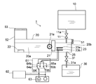
- the side surface sectional view showing roughly the functional water generation mode of the functional water generating device concerning a 1st embodiment of the present invention.
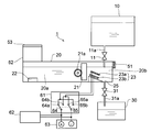
- Side surface sectional drawing which shows schematically the detachment
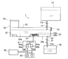
- Side surface sectional drawing which shows schematically the functional water generating apparatus which concerns on 2nd Embodiment of this invention.
- Side surface sectional drawing which shows schematically the functional water production
- Side surface sectional drawing which shows schematically the detachment
- FIG. 1 is a side cross-sectional view schematically showing a functional water generator 1 according to the first embodiment.
- the functional water generator 1 includes a water tank 20, a water supply tank 10, and a drain tank 30. Inside the water storage tank 20, there are an ultrasonic vibrator 22 (a diffusion part), a partition part 21, and a voltage application part 23.
- the water storage tank 20 is partitioned into a first water storage part 20 a and a second water storage part 20 b through a partition part 21.
- An ultrasonic transducer 22 is disposed in the first water storage unit 20a, and a voltage application unit 23 is disposed in the second water storage unit 20b.
- the ultrasonic vibrator 22 mists or steams the water in the water storage tank 20 and diffuses it into the air.
- the storage tank 20 has a blower 51 and a guide part 52, and the diffused steam or mist is sent along the guide part 52 on the air flow generated from the blower 51, and is sent to the outside through the blower port 53. Blow out.
- the blower port 53 on the first water storage unit 20a side and the blower 51 on the second water storage unit 20b side, the gas generated in the first electrode 23a or the second electrode 23b is placed on the airflow and blown. It is possible to efficiently discharge from the mouth 53.
- the voltage application unit 23 includes a first electrode 23 a and a second electrode 23 b that are immersed in the water storage tank 20, and the first electrode 23 a and the second electrode 23 b are connected to the switching circuit 61.
- the switching circuit 61 is connected to a constant current generation source 63 via a control device 62.
- the switching circuit 61a includes switches 64 and 65. When the switch 64 is connected to the terminal 64a and the switch 65 is connected to the terminal 65a, a voltage is applied so that the first electrode 23a is an anode and the second electrode 23b is a cathode. Is done.
- the switch 64 when the switch 64 is connected to the terminal 64b and the switch 65 is connected to the terminal 65b, a voltage is applied so that the first electrode 23a is a cathode and the second electrode 23b is an anode. Switching of the switches 64 and 65 is controlled by the control device 62.
- the partition portion 21 has a rack (not shown) that meshes with a gear 21a that is pivotally supported by the water storage tank 20.
- the first water storage portion 20a and the second water storage portion are moved up and down in the water storage tank 20 by the rotation of the gear 21a.
- 20b is opened and closed.
- the raising / lowering of the partition part 21 is controlled by the drive part (not shown), and water flows between the 1st water storage part 20a and the 2nd water storage part 20b in the water storage tank 20 in the open state which the partition part 21 raised. To do.
- the lower end of the partition portion 21 is in contact with the bottom surface of the water storage tank 20. Thereby, in water storage tank 20, water does not mix between the 1st water storage part 20a and the 2nd water storage part 20b.
- the water storage tank 20 and the water supply tank 10 communicate with each other via a flow path 11a provided with a valve 11.
- the lower end of the flow path 11a extends to the second water reservoir 20b, and the water in the water supply tank 11 can be supplied to the second water reservoir 20b by opening the valve 11.
- the water tank 10 is a container which can be removed from the water storage tank 20, and when the water in the water supply tank 10 runs out, the water supply tank 10 can be removed and the city water can be put directly.
- the water storage tank 20 and the drainage tank 30 communicate with each other through a flow path 31a provided with a valve 31.
- the channel 31a communicates with the drainage tank 30 via a drainage port 31b that opens at the bottom surface of the second water storage unit 20b. Thereby, the water in the 2nd water storage part 20b can be drained to the drainage tank 30 by opening the valve 31.
- the drain tank 30 is also a container that can be removed from the water storage tank 20, and when the water in the drain tank 30 increases, it can be removed and the water in the drain tank 30 can be directly discarded.
- mist / steam generating device such as a heating type (steam type) or a vaporization type (heatless fan type) may be used as the radiating unit.
- a device combining a plurality of devices selected from these can be used.
- a hybrid mist / steam generator combining a heating method and a vaporization method may be used.
- the first electrode 23a and the second electrode 23b of the voltage application unit 11 are plate-like electrodes and are inclined in the horizontal direction and arranged in parallel to each other.
- the first electrode 23a is a metal electrode, such as a titanium electrode whose surface is coated with a metal (for example, platinum) that is easily electrolyzed with water.
- a metal for example, platinum
- an electrode made of titanium alone or an electrode made of platinum alone may be used.
- the second electrode 23b is a carbon electrode made of a conductive carbon material as an ion adsorption electrode.
- This carbon electrode is formed by agglomerating granular activated carbon.
- a porous adsorption surface can be formed on the surface of the electrode by using granular activated carbon.
- hardness components such as Mg ion and Ca ion, which are dissolved in water such as tap water can be effectively adsorbed on the porous adsorption surface.
- a conductive sheet formed by aggregating granular activated carbon and conductive carbon may be used.
- an activated carbon block formed by solidifying activated carbon particles may be used.
- the activated carbon fiber cloth formed using activated carbon fiber may be sufficient.
- the ion (M 2+ ) of the hardness component (M) such as Mg ion and Ca ion dissolved in water such as tap water has a porous property that the ion adsorption electrode has as shown in the formula (3). Adsorbed as a hardness component (M) using the material adsorption surface.
- the second electrode 23b generates hydroxide ions and hydrogen gas.
- an ion-adsorbing electrode is used for the second electrode 23b, and the generation of hydroxide ions is limited compared to the case where a metal electrode is used. For this reason, hydrogen ions generated at the first electrode 23a increase, the pH of the water decreases, and weakly acidic functional water is generated.
- the pH of the acidic water produced is preferably 3 or more and 5 or less.
- Bacterial infection can be prevented by the bactericidal effect of acidic functional water by misting or steaming this functional water in the ultrasonic vibrator 22 and releasing it into the air.
- the human body has an effect of activating the skin and the like by tightening the skin due to the astrogen effect on the skin.
- the acid concentration is higher in the second water reservoir 20b in which the first electrode 23a and the second electrode 23b are disposed than in the first water reservoir 20a. Due to the convection of water and the diffusion of hydrogen ions in the water storage unit 20a and the second water storage unit 20b, the pH of the entire water storage tank 20 becomes uniform after a predetermined time. For this reason, it is preferable to apply a voltage to the first electrode 23a and the second electrode 23b and to mist or steam the ultrasonic transducer 22 and dissipate it in the air after a predetermined time has elapsed.
- FIG. 2 is a side sectional view schematically showing the desorption mode of the functional water generator 1.
- the desorption mode is executed.
- the partition unit 20 is held in the lowered state, and the functional water generated in the functional water generation mode is isolated from the second water storage unit 20b in the first water storage unit 20a.
- valve 11 is opened to supply the water in the water supply tank 10 to the second water storage unit 20b, and a voltage opposite to that at the time of electrolysis is applied to the first electrode 23a and the second electrode 23b. That is, the voltage is applied so that the metal electrode as the first electrode 23a is the cathode and the carbon electrode as the second electrode 23b is the anode.
- the hardness component M adsorbed on the carbon electrode surface of the second electrode 23b becomes M 2+ as shown in the formula (5) and is eluted in water.
- the first water storage section 20a is isolated from the second water storage section 20b and the partition section 21, and the alkaline water generated in the second water storage section 20b is not mixed with the first water storage section 20a.
- the functional water generated before the start of the desorption mode can be misted or steamed in the ultrasonic vibrator 22 and diffused into the air.
- the radiation by the ultrasonic transducer 22 is not necessarily executed in the desorption mode, and the radiation by the ultrasonic transducer 22 may be stopped in the desorption mode.
- an amount of about 1/2 to 1/10 of the functional water generated in the functional water generation mode is stored in the second water storage unit 20b and a reverse voltage is applied. Is preferred. Further, it is more preferable to store a water amount of about 1/2 to 1/5 of the functional water generated in the functional water generation mode in the second water storage unit 20b and apply a reverse voltage. By setting the amount of water to about 1/2 to 1/5, the adsorbed hardness component can be completely desorbed.
- the entire first electrode 23a and the second electrode 23b are immersed in the water in the second water reservoir 20b in the desorption mode. Thereby, a hardness ion component can be reliably eluted in water.
- the valve 31 After applying a voltage sufficient to desorb the adsorbed hardness component, the valve 31 is opened, and the residual water containing a large amount of hardness ion component (M 2+ ) remaining in the second water tank 20b is discarded in the drain tank 30. End the desorption mode. After the desorption mode ends, the functional water generation mode can be started again.
- the functional water generated in the functional water generation mode in the first water reservoir 20a is isolated from the second water reservoir 20b by closing the partition 21 in the desorption mode.
- the water containing the cation desorbed by applying a voltage in the direction opposite to that in the functional water generation mode between the electrodes in the second water reservoir 20b is not mixed with the functional water in the first water reservoir 20a. Therefore, even after the start of the desorption mode, the functional water generated before the start of the desorption mode can be diffused into the air by being misted or steamed by the diffusion unit.
- the drive part (not shown) which raises / lowers the partition part 21 up and down is provided, and the lower end of the partition part 21 lowered
- the residual water of the second water storage unit 20b is drained to the drain tank 30 after the end of the desorption mode. Can do. Thereby, it is not necessary to discard the residual water in the water storage tank 20 after the end of the desorption mode. For this reason, the transition from the desorption mode to the functional water generation mode is smoothly performed, and convenience can be improved.
- FIG. 3 is a side sectional view schematically showing the functional water generating apparatus 1 according to the second embodiment.
- the same part as 1st Embodiment attaches
- an inclined surface 24 is provided on the bottom surface of the second water reservoir 20b.
- the inclined surface 24 is formed to descend toward the drain port 31b.
- the first electrode 23 a and the second electrode 23 b are arranged along the inclined surface 24.
- the hard ion component (M 2+ ) dissolved in the desorption mode is crystallized and precipitated, the crystal is guided to the drain port 31 through the inclined surface 24, the first electrode 23 a or the second electrode 23 b. Therefore, the crystals can be reliably discarded into the drain tank 30. Thereby, it can prevent that the production
- ⁇ Third Embodiment> 4 and 5 are side cross-sectional views schematically showing the functional water generating device 1 according to the third embodiment.
- the same part as 1st Embodiment attaches
- the partition portion 21 is formed in a plate shape, and the lower end portion is pivotally attached to the bottom portion of the water storage tank 20 so as to be pivotable. 21 is erected with its lower end in contact with the bottom surface of the water storage tank 20.
- the partition part 21 stands or inclines and partitions the 1st water storage part 20a and the 2nd water storage part 20b so that opening and closing is possible.
- first electrode 23a and the second electrode 23b are attached to the partition part 21, and when the partition part 21 is erected, the first electrode 23a and the second electrode 23b are arranged to face the second water storage part 20b. Yes.
- the partition portion 21 is installed to be inclined, and in the desorption mode, the partition portion 21 is erected to isolate the first water storage portion 20a and the second water storage portion 20b. Moreover, the partition part 21 inclines to the ultrasonic transducer
- FIG. 6 is a side sectional view showing the partition portion 21 in an enlarged manner
- FIG. 7 is a plan view of the partition portion 21 viewed from the second water storage portion 20b side.
- the partition part 21 has a recess 21b formed by opening a part of one surface of a plate-shaped resin case 21e, and a first electrode 23a and a second electrode 23b are provided in the recess 21b.
- the first electrode 23a is disposed outside the second electrode 23b, and the first electrode 23a and the second electrode 23b are fixed at a predetermined interval.
- the first electrode 23 a is formed in a mesh shape, and a part of the second electrode 23 b is exposed to the outside of the partition portion 21 through the gap S of the first electrode 23 a. Accordingly, water flows between the first electrode 23a and the second electrode 23b through the gap S.
- fin portions 21 d are provided on both sides of the partition portion 21.
- the fin portion 21d is made of an elastic body, and slides while pressing the side wall of the water storage tank 20 when the partition portion 21 is opened and closed. Thereby, when the partition part 21 stands upright, the 1st water storage part 20a and the 2nd water storage part 20b can be interrupted
- a pivot shaft 21c is provided at the lower portion of the partition portion 21, and the partition portion 21 rotates with the pivot shaft 21c as a fulcrum.
- the partition part 21 of this embodiment when using a heating-type radiation
- FIG. 8 is a side sectional view schematically showing the functional water generating apparatus 1 according to the fourth embodiment.
- the same part as 1st Embodiment attaches
- the water storage tank 20 and the drainage tank 30 communicate with each other via flow paths 31a and 32a.
- a valve 31 is provided in the flow path 31a.
- a pump 32 is provided in the flow path 32a. The lower end of the flow path 32 a is disposed in the upper layer portion of the drain tank 30.
- the partition unit 20 When the desorption mode is started, the partition unit 20 is lowered and closed, and the functional water generated in the functional water generation mode in the first water storage unit 20a is isolated from the second water storage unit 20b. Thereafter, the water in the upper layer of the residual water remaining in the drain tank 30 is supplied to the second water storage unit 20b by the pump 32. At this time, residual water discarded in the previous desorption mode is accumulated in the drain tank 30, but the hardness ion component (M 2+ ) eluted in the residual water becomes a scale component such as CaCO 3 or MgCO 3 at the bottom. It is precipitated. For this reason, the water of the upper layer part in the drainage tank 30 has a low concentration of the hardness ion component (M 2+ ), and can be reused for desorption of the adsorbed component.
- M 2+ hardness ion component
- the water in the water supply tank 10 used in the desorption mode can be reduced. Therefore, the number of times of replenishing the water in the water supply tank 10 can be reduced and a larger amount of functional water can be generated with a single water supply.
- the water supply tank 10 may be omitted in the first to fourth embodiments.
- the user may supply water directly to the water storage tank 20 with a kettle or the like.
- the drain tank 30 may be omitted.
- the residual water in the water tank 20 may be directly discarded before the start of the functional water generation mode.
- city water can be supplied to the water storage tank 20.
- first electrode 23a and the second electrode 23b can be variously changed, and various functional waters can be generated.
- a metal electrode a titanium electrode whose surface is coated with platinum, size: 90 mm ⁇ 70 mm
- the first electrode 23a is the anode and the second electrode in the functional water generation mode.
- ions (M 2+ ) of hardness component (M) such as Mg ion and Ca ion dissolved in water such as tap water have the ion adsorption electrode as shown in the above formula (3). Adsorbed as a hardness component (M) using the porous adsorption surface.
- the second electrode 23b generates hydroxide ions (OH ⁇ ) in Expression (6) and hydrogen gas.
- the chlorine gas generated in the formula (7) is easily dissolved in water as shown in the formulas (9) and (10), and changes into hypochlorous acid and hypochlorite ions.
- the concentration of hypochlorite ions varies depending on the metal electrode coating material used for the first electrode 23a.
- any one metal (or an alloy thereof) of platinum, gold, palladium, rhodium, and iridium, or an oxide thereof can be used.
- iridium oxide is coated instead of platinum, the concentration of hypochlorous acid can be dramatically increased.
- M becomes M 2+ as shown in the above formula (5) and is eluted in water.
- an ion adsorption electrode such as a carbon electrode may be used for the first electrode 23a and the second electrode 23b.
- a voltage is applied so that the first electrode 23a serves as an anode and the second electrode 23b serves as a cathode, thereby adsorbing anions in the solution to the first electrode 23a, and the second electrode 23b. Can adsorb cations in the solution.
- the adsorption component adsorbed on the first electrode 23a and the second electrode 23b can be desorbed by applying a voltage in the opposite direction to the functional water generation mode in the desorption mode.
- the voltage application unit 11 is not limited to the case where a pair of the first electrode 23a and the second electrode 23b is provided, and may be composed of three or more electrodes.
- the soft weak acidic water, hard weak alkaline water, neutral High concentration hypochlorous acid water can be produced.
- the adsorption component adsorbed on the first electrode 23a and the second electrode 23b can be desorbed by applying a voltage in the opposite direction to the functional water generation mode in the desorption mode.
- the water storage tank 20 can also be electrolyzed by supplying a solution containing at least one ion other than hydrogen ions (H +) and hydroxide ions (OH ⁇ ).
- H + hydrogen ions
- OH ⁇ hydroxide ions
- it is a mixed solvent of water and an organic solvent
- the organic solvent include alcohols such as ethanol, ketones such as acetone, propylene carbonate, ethylene carbonate, and dimethyl carbonate.
- a functional water generator such as a humidifier.
Landscapes
- Chemical & Material Sciences (AREA)
- Life Sciences & Earth Sciences (AREA)
- Chemical Kinetics & Catalysis (AREA)
- Health & Medical Sciences (AREA)
- General Chemical & Material Sciences (AREA)
- Water Supply & Treatment (AREA)
- Engineering & Computer Science (AREA)
- Environmental & Geological Engineering (AREA)
- Hydrology & Water Resources (AREA)
- Organic Chemistry (AREA)
- Electrochemistry (AREA)
- Epidemiology (AREA)
- Animal Behavior & Ethology (AREA)
- General Health & Medical Sciences (AREA)
- Public Health (AREA)
- Veterinary Medicine (AREA)
- Water Treatment By Electricity Or Magnetism (AREA)
Abstract
本発明は、仕切部21を開いて電極23a、23b間に電圧を印加して電気分解により機能水を生成する機能水生成モードと、仕切部21を閉じて電極23a、23b間に機能水生成モードと逆方向の電圧を印加して電極23a、23bに吸着した吸着成分を脱離させる脱離モードとを設け、脱離モード時に放散部22が第1貯水部20aに配されるとともに電極23a、23bが第2貯水部20bに配される。
Description
本発明は、機能水を生成する機能水生成装置に関する。
従来の機能水生成装置が特許文献1に開示されている。この機能水生成装置は貯水槽内に電圧印加部と放散部とを備える。電圧印加部は貯水槽内に配された一対の電極間に電圧を印加して貯水槽内の水を電気分解する。これにより、貯水槽内の水から酸性水から成る機能水を生成することができる。このとき、カソードとなる電極では水道水等の水中に溶存しているMgイオン、Caイオンなどの硬度イオン成分(M2+)が硬度成分(M)となって吸着される。放散部では貯水槽内で生成された機能水をミスト化又はスチーム化して空気中に放散する。
また、電極に過度に硬度成分が吸着すると機能水の生成効率が低下するため、脱離モードを設けて電気分解時とは逆方向の電圧を印加する。これにより、電極に吸着した硬度成分が硬度イオン成分(M2+)として水中に溶出させることができる。
上記従来の機能水生成装置によると、脱離モードにおいて貯水槽内の水は硬度イオン成分(M2+)が水中に溶出して硬質化するとともにアルカリ化する。このため、脱離モード開始後、放散部が空気中に放散するミスト又はスチームには硬度イオン成分等の吸着成分が混入することが問題になっていた。
本発明は、脱離モード開始後においても脱離モード開始前に生成した機能水をミスト化又はスチーム化して空気中に放散することができる機能水生成装置を提供することを目的とする。
上記目的を達成するために本発明は、水を貯水する貯水槽と、前記貯水槽内の水をミスト化又はスチーム化して空気中に放散する放散部と、前記貯水槽内に浸漬して電圧が印加される一対の電極と、前記貯水槽内を第1貯水部と第2貯水部とに開閉可能に仕切る仕切板とを備え、前記仕切部を開いて前記電極間に電圧を印加して電気分解により機能水を生成する機能水生成モードと、前記仕切部を閉じて前記電極間に前記機能水生成モードと逆方向の電圧を印加して前記電極に吸着した吸着成分を脱離させる脱離モードとを設け、前記脱離モード時に前記放散部が第1貯水部に配されるとともに前記電極が第2貯水部に配されることを特徴としている。
この構成によると、機能水生成モードにおいて仕切部を開いて電極間に電圧を印加して電気分解を行うことにより、貯水槽に貯水された水全体から機能水が生成される。また、脱離モードにおいて仕切部を閉じることにより、第1貯水部に機能水生成モードで生成された機能水が第2貯水部から隔離される。これにより、第2貯水部で電極間に機能水生成モードと逆方向の電圧を印加して電極に吸着した吸着成分を脱離した場合にも脱離した吸着成分を含む水が第1貯水部の機能水に混和しない。
また、本発明は、上記構成の機能水生成装置において、前記仕切部を上下に昇降させる駆動部を備え、前記機能水生成モード時に前記駆動部により降下した前記仕切部の下端が前記貯水槽の底面に接することを特徴としている。
また、本発明は、上記構成の機能水生成装置において、前記仕切部が板状に形成されるとともに下端部を前記貯水槽の底部に軸支して回動可能に取り付けられ、前記機能水生成モード時に前記仕切部が下端を前記貯水槽の底面に接して立設されることを特徴としている。
また、本発明は、上記構成の機能水生成装置において、前記電極が前記仕切部に配され、前記仕切部が立設したときに前記電極が第2貯水部に臨むことを特徴としている。
また、本発明は、上記構成の機能水生成装置において、第2貯水部の水を排水する排水タンクを備えるとともに前記排水タンク内の上層部の水を第2貯水部に送出するポンプを設けたこと特徴としている。
また、本発明は、上記構成の機能水生成装置において、第2貯水部に水を給水する脱着可能な給水タンクを設けたこと特徴としている。
また、本発明は、上記構成の機能水生成装置において、第2貯水部の底面に開口する排水口を介して排水する排水タンクを備え、第2貯水部の底面に前記排水口に向かって下がる傾斜面を設け、前記電極を前記傾斜面に沿って配したことを特徴としている。
本発明によると、脱離モードにおいて仕切部を閉じることにより、第1貯水部内の機能水生成モードで生成された機能水が第2貯水部から隔離される。これにより、第2貯水部で電極間に機能水生成モード時とは逆方向の電圧を印加して脱離した吸着成分を含む水が第1貯水部の機能水に混和しない。したがって、脱離モード開始後においても脱離モードの開始前に生成した機能水を放散部でミスト化又はスチーム化して空気中に放散することができる。
[第1実施形態]
以下に本発明の実施形態を図面の参照にて説明する。図1は第1実施形態に係る機能水生成装置1を概略的に示す側面断面図である。
以下に本発明の実施形態を図面の参照にて説明する。図1は第1実施形態に係る機能水生成装置1を概略的に示す側面断面図である。
機能水生成装置1は貯水槽20と給水タンク10と排水タンク30とを備える。貯水槽20内部には超音波振動子22(放散部)と仕切部21と電圧印加部23とを有する。貯水槽20は仕切部21を介して第1貯水部20aと第2貯水部20bとに仕切られる。第1貯水部20aには超音波振動子22が配され、第2貯水部20bには電圧印加部23が配される。
超音波振動子22は貯水槽20内の水をミスト化又はスチーム化して空中に放散する。また、貯槽槽20は送風機51とガイド部52とを有し、放散されたスチーム又はミストは送風機51から発生した気流に乗ってガイド部52に沿って送出され、送風口53を介して外部に吹出す。なお、送風口53を第1貯水部20a側に配し、送風機51を第2貯水部20b側に配すことで、第1電極23a又は第2電極23bで発生したガスを気流に乗せて送風口53から効率良く排出することができる。
電圧印加部23は貯水槽20に浸漬される第1電極23aと第2電極23bとを有し、第1電極23a及び第2電極23bはスイッチング回路61に接続されている。スイッチング回路61は制御装置62を介して定電流発生源63と接続されている。スイッチング回路61aはスイッチ64、65を備え、スイッチ64を端子64aに接続し、スイッチ65を端子65aに接続したとき、第1電極23aがアノード、第2電極23bがカソードとなるように電圧が印加される。一方、スイッチ64を端子64bに接続し、スイッチ65を端子65bに接続したとき、第1電極23aがカソード、第2電極23bがアノードとなるように電圧が印加される。スイッチ64、65の切り替えは制御装置62で制御される。
仕切部21は貯水槽20に軸支されたギア21aに噛合するラック(不図示)を有し、ギア21aの回転により貯水槽20内を昇降することで第1貯水部20aと第2貯水部20bとを開閉可能に仕切る。なお、仕切部21の昇降は駆動部(不図示)により制御され、仕切部21が上昇した開状態では貯水槽20内において第1貯水部20aと第2貯水部20bとの間で水が流通する。一方、仕切部21が降下した閉状態では仕切部21の下端が貯水槽20の底面に接する。これにより、貯水槽20内において第1貯水部20aと第2貯水部20bとの間で水が混和しない。
貯水槽20と給水タンク10とは弁11が設けられた流路11aを介して連通している。流路11aの下端は第2貯水部20bへ延びており、弁11を開くことによって給水タンク11内の水を第2貯水部20bへ給水することができる。また、水タンク10は貯水槽20から取り外し可能な容器であり、給水タンク10内の水が無くなると、給水タンク10を取り外して市水を直接入れることができる。
貯水槽20と排水タンク30とは弁31が設けられた流路31aを介して連通している。流路31aは第2貯水部20bの底面に開口する排水口31bを介して排水タンク30に連通している。これにより、弁31を開くことで第2貯水部20b内の水を排水タンク30へ排水することができる。なお、排水タンク30も貯水槽20から取り外し可能な容器であり、排水タンク30内の水が増加すると、取り外して排水タンク30内の水を直接廃棄することができる。
超音波振動子22は貯水槽20内の水に浸漬した状態にある間、水をミスト化又はスチーム化して空気中に放散可能な状態となる。超音波振動子22の替わりに、加熱式(スチーム式)や気化式(ヒートレスファン式)等のミスト・スチーム発生装置を放散部として用いてもよい。また、これらから選ばれる複数の装置を組み合わせた装置を用いることもでき、例えば、加熱式と気化式を組み合わせたハイブリッド式のミスト・スチーム発生装置を用いてもよい。
電圧印加部11の第1電極23a及び第2電極23bは平板状の電極であり、水平方向に傾斜して互いに平行に配置されている。第1電極23aは金属電極であり、水の電気分解が生じやすい金属(例えば白金)で表面をコーティングしたチタン電極等を用いる。なお、チタン単体からなる電極や、白金単体からなる電極を用いてもよい。また、平板状以外に、メッシュ状、棒状の第1電極23aを用いてもよい。
第2電極23bはイオン吸着電極としては導電性の炭素材料からなる炭素電極が用いられる。この炭素電極は粒状活性炭を凝集させて形成される。粒状活性炭を用いることで電極の表面に多孔質吸着面を形成することができる。これにより、水道水等の水中に溶存しているMgイオン、Caイオンなどの硬度成分を多孔質吸着面に効果的に吸着させることができる。また、粒状活性炭と導電性カーボンとを凝集させることによって形成された導電性シートを用いてもよい。また、活性炭粒子を固めて形成された活性炭ブロックであってもよい。また、活性炭繊維を用いて形成された活性炭繊維クロスであってもよい。
[機能水生成モード]
以上のように構成された機能水生成装置1において、給水タンク10から貯水槽20に水が供給されて機能水生成モードが実行される。機能水生成モードでは仕切部21が上昇した開状態で保持され、貯水槽20内において第1貯水部20aと第2貯水部20bとの間で水が流通している。また、機能水生成モードでは第1電極23aがアノード、第2電極23bがカソードとなるように電圧を印加する。これにより、第1電極23aでは式(1)、(2)に示すように、水素イオン(H+)が生成するとともに酸素ガスや塩素ガスが発生する。
以上のように構成された機能水生成装置1において、給水タンク10から貯水槽20に水が供給されて機能水生成モードが実行される。機能水生成モードでは仕切部21が上昇した開状態で保持され、貯水槽20内において第1貯水部20aと第2貯水部20bとの間で水が流通している。また、機能水生成モードでは第1電極23aがアノード、第2電極23bがカソードとなるように電圧を印加する。これにより、第1電極23aでは式(1)、(2)に示すように、水素イオン(H+)が生成するとともに酸素ガスや塩素ガスが発生する。
H2O→1/2O2+2H++2e-・・・(1)
2Cl→Cl2+2e- ・・・(2)
2Cl→Cl2+2e- ・・・(2)
一方、第2電極23bでは水道水等の水中に溶存しているMgイオン、Caイオンなどの硬度成分(M)のイオン(M2+)が式(3)に示すようにイオン吸着電極の有する多孔質吸着面を利用して硬度成分(M)となって吸着する。
M2++2e-→M・・・(3)
また、第2電極23bでは式(4)に示すように水酸化物イオンが生成するとともに水素ガスが発生する。このとき、第2電極23bにイオン吸着電極を用いており、金属電極を用いた場合と比較して水酸化物イオンの発生は限定的である。このため、第1電極23aで発生する水素イオンが増加して水のpHが減少して弱酸性の機能水が生成される。
2H2O+2e-→H2+2OH- ・・・(4)
生成される酸性水のpHは3以上5以下であることが好ましい。この機能水を超音波振動子22においてミスト化又はスチーム化して空気中に放散することにより、酸性の機能水の制菌効果によって細菌感染の予防が可能となる。また、人体に対しては肌に対するアストリンゼン効果による皮膚等の活性化、肌の引き締め効果がある。
また、上記式(4)に示すように第2電極23bでは水素ガスが発生するが、水素ガスの一部は水中に溶解する。このとき、水素ガスが溶存した機能水が貯水槽20内で対流循環し、貯水槽20内の水の酸化還元電位(Oxidation-Reduction Potential(ORP))が-100~+100mVまで下がる。なお、通常の水道水の酸化還元電位は+250~+400mV程度である。
酸性水中の酸化還元電位を下げることにより、肌に対するアンチエージング効果(参考文献:温泉科学、第55巻、p.55~63、2005年)がより向上する。なお、酸性水を2槽式電解槽で生成すると、酸性水が生成する槽ではORPも+500mV以上に増加する。このため、酸性水によりアストリンゼン効果はあるが、酸化作用も併せて有するため、理美容用途として積極的に使用することができない。
なお、機能水生成モード開始直後において、第1電極23a及び第2電極23bが配された第2貯水部20b内の方が第1貯水部20a内に比べて酸性濃度が高くなるが、第1貯水部20a及び第2貯水部20b内での水の対流と水素イオンの拡散により、所定時間経過後、貯水槽20全体のpHは均一になる。このため、第1電極23a及び第2電極23bに電圧を印加して所定時間経過後、超音波振動子22においてミスト化又はスチーム化して空気中に放散することが好ましい。
[脱離モード]
図2は機能水生成装置1の脱離モードを概略的に示す側面断面図である。機能水のミスト化又はスチーム化により貯水槽20内の水位が所定高さより低くなると、脱離モードが実行される。脱離モードでは仕切部20が降下した閉状態で保持され、第1貯水部20aに機能水生成モードで生成された機能水が第2貯水部20bから隔離される。
図2は機能水生成装置1の脱離モードを概略的に示す側面断面図である。機能水のミスト化又はスチーム化により貯水槽20内の水位が所定高さより低くなると、脱離モードが実行される。脱離モードでは仕切部20が降下した閉状態で保持され、第1貯水部20aに機能水生成モードで生成された機能水が第2貯水部20bから隔離される。
次に弁11を開いて給水タンク10内の水を第2貯水部20bへ供給し、第1電極23a及び第2電極23bに電気分解時とは逆向きの電圧を印加する。つまり、第1電極23aである金属電極がカソード、第2電極23bである炭素電極がアノードとなるように電圧を印加する。
これにより、第2電極23bの炭素電極表面に吸着した硬度成分Mが式(5)に示すようにM2+となって水中に溶出する。
M→M2++2e-・・・(5)
一方、第1電極23aの金属電極の表面では、上記式(4)に示すように水素ガスとOH-イオンが発生する。これにより、第2貯水部20b内の残留水中にイオン吸着電極からCaイオン、Mgイオン等の硬度イオン成分を溶出させるとともに、水酸化物イオンが増加して水のpHは上昇してアルカリ化する。
このとき、第1貯水部20aは第2貯水部20bと仕切部21を介して隔離されており、第2貯水部20bで生成されたアルカリ水が第1貯水部20aに混和することない。このため、脱離モードにおいても脱離モード開始前に生成した機能水を超音波振動子22においてミスト化又はスチーム化して空気中に放散することができる。なお、脱離モードにおいて超音波振動子22による放散は必ず実行されるわけではなく、脱離モードにおいて超音波振動子22による放散を停止してもよい。
また、吸着した硬度成分を充分に脱着するためには機能水生成モードにおいて生成した機能水の1/2~1/10程度の水量を第2貯水部20bに貯水して逆電圧を印加することが好ましい。また、機能水生成モードにおいて生成した機能水の1/2~1/5程度の水量を第2貯水部20bに貯水して逆電圧を印加することがより好ましい。1/2~1/5程度の水量とすることにより、吸着した硬度成分を完全に脱着させることができる。
なお、脱離モードにおいて第2貯水部20bに貯水される水が機能水生成モードにおいて生成した機能水の1/5より少ない場合、脱着が充分に行われず、次の機能水生成モードにおいて硬度成分の吸着力が低下する。このため、脱離モードの開始時に第2貯水部20b内の水が少ない場合、給水タンク10から水を供給する必要がある。
また、脱離モードにおいて第2貯水部20b内の水の中に第1電極23a及び第2電極23b全体が浸漬している状態に維持されることが好ましい。これにより、硬度イオン成分を水中に確実に溶出することができる。
吸着した硬度成分を脱着するのに十分な電圧を印加した後、弁31を開いて第2貯水槽20bに残留した硬度イオン成分(M2+)を多く含む残留水を排水タンク30に廃棄して脱離モードを終了する。脱離モードの終了後、再び機能水生成モードを開始することができる。
本実施形態によると、脱離モードにおいて仕切部21を閉じることにより、第1貯水部20a内の機能水生成モードで生成された機能水が第2貯水部20bから隔離される。これにより、第2貯水部20bで電極間に機能水生成モード時とは逆方向の電圧を印加して脱離した陽イオンを含む水が第1貯水部20aの機能水に混和しない。したがって、脱離モード開始後においても脱離モード開始前に生成した機能水を放散部でミスト化又はスチーム化して空気中に放散することができる。
また、仕切部21を上下に昇降させる駆動部(不図示)を備え、機能水生成モード時に駆動部により降下した仕切部21の下端が貯水槽20の底面に接して第1貯水部20aと第2貯水部20bとを確実に遮断することができる。
また、第2貯水部20bの水を排水するとともに貯水槽20から脱着可能な排水タンク30を備えることにより、脱離モードの終了後に第2貯水部20bの残留水を排水タンク30へ排水することができる。これにより、脱離モード終了後に逐次貯水槽20内の残留水を廃棄する必要がない。このため、脱離モードから機能水生成モードへの移行が円滑に行われ、利便性を向上させることができる。
<第2実施形態>
図3は第2実施形態に係る機能水生成装置1を概略的に示す側面断面図である。なお、第1実施形態と同一部分は同一符号を付して説明を省略する。第1実施形態に対して第2実施形態は第2貯水部20bの底面に傾斜面24が設けられている。傾斜面24は排水口31bに向かって下がって形成されている。また、第1電極23a及び第2電極23bは傾斜面24に沿って配されている。これにより、脱離モードにおいて溶解した硬質イオン成分(M2+)が結晶化して析出した場合、結晶が傾斜面24、第1電極23a又は第2電極23bを伝って排水口31へ導かれる。したがって、結晶を排水タンク30へ確実に廃棄することができる。これにより、機能水生成モードを開始したときに貯水槽20内に結晶化した硬質イオン成分(M2+)が残留することにより、機能水の生成効率が低下するのを防止することができる。
図3は第2実施形態に係る機能水生成装置1を概略的に示す側面断面図である。なお、第1実施形態と同一部分は同一符号を付して説明を省略する。第1実施形態に対して第2実施形態は第2貯水部20bの底面に傾斜面24が設けられている。傾斜面24は排水口31bに向かって下がって形成されている。また、第1電極23a及び第2電極23bは傾斜面24に沿って配されている。これにより、脱離モードにおいて溶解した硬質イオン成分(M2+)が結晶化して析出した場合、結晶が傾斜面24、第1電極23a又は第2電極23bを伝って排水口31へ導かれる。したがって、結晶を排水タンク30へ確実に廃棄することができる。これにより、機能水生成モードを開始したときに貯水槽20内に結晶化した硬質イオン成分(M2+)が残留することにより、機能水の生成効率が低下するのを防止することができる。
<第3実施形態>
図4、図5は第3実施形態に係る機能水生成装置1を概略的に示す側面断面図である。なお、第1実施形態と同一部分は同一符号を付して説明を省略する。第1実施形態に対して第3実施形態は仕切部21が板状に形成されるとともに下端部を貯水槽20の底部に軸支して回動可能に取り付けられ、機能水生成モード時に仕切部21が下端を貯水槽20の底面に接して立設される。これにより、仕切部21が立設または傾斜して第1貯水部20aと第2貯水部20bとを開閉可能に仕切る。
図4、図5は第3実施形態に係る機能水生成装置1を概略的に示す側面断面図である。なお、第1実施形態と同一部分は同一符号を付して説明を省略する。第1実施形態に対して第3実施形態は仕切部21が板状に形成されるとともに下端部を貯水槽20の底部に軸支して回動可能に取り付けられ、機能水生成モード時に仕切部21が下端を貯水槽20の底面に接して立設される。これにより、仕切部21が立設または傾斜して第1貯水部20aと第2貯水部20bとを開閉可能に仕切る。
また、第1電極23a及び第2電極23bが仕切部21に取り付けられ、仕切部21が立設したときに第1電極23a及び第2電極23bは第2貯水部20bに臨むように配されている。
また、機能水生成モードにおいて仕切部21は傾斜して設置され、脱離モードにおいて仕切部21が立設して第1貯水部20aと第2貯水部20bを隔離する。また、仕切部21は超音波振動子22側に傾斜する。これにより、超音波振動子22は第1電極23a及び第2電極23bで生成された濃度の高い機能水を早期にミスト化又はスチーム化して空気中に放散することができる。
図6は仕切部21を拡大して示す側方断面図であり、図7は仕切部21を第2貯水部20b側から視た平面図である。仕切部21は板状の樹脂ケース21eの片面の一部が開口して形成される凹部21bを有し、凹部21b内に第1電極23aと第2電極23bとが設けられている。また、第1電極23aは第2電極23bより外側に配され、第1電極23aと第2電極23bは所定間隔離れて固定されている。第1電極23aはメッシュ状に形成されており、第1電極23aの隙間Sを介して第2電極23bの一部が仕切部21の外部に露出している。従って、隙間Sを介して第1電極23a及び第2電極23bの間を水が流通する。
また、仕切部21の両側部にはヒレ部21dが設けられている。ヒレ部21dは弾性体から成り、仕切部21の開閉時に貯水槽20の側壁を押圧しながら摺動する。これにより、仕切部21が立設したときに第1貯水部20aと第2貯水部20bとを確実に遮断することができる。また、仕切部21の下部には枢支軸21cが設けられ、枢死軸21cを支点にして仕切部21が回動する。
なお、超音波振動子22に替えてヒータ等の加熱式の放散部を用いる場合、本実施形態の仕切部21を用いることが好ましい。これは機能水生成モード及び脱離モードの切り替え時に仕切部21が回動するため第1電極23a及び第2電極23bが放熱部からの熱に常にさらされ続けることはない。これにより、熱による電極の劣化を防ぎ、長寿命化を図ることができる。このとき、樹脂ケース21eは耐熱性樹脂を用いることが好ましい。例えば、ポリイミド系の樹脂材料が好適である。
<第4実施形態>
図8は第4実施形態に係る機能水生成装置1を概略的に示す側面断面図である。なお、第1実施形態と同一部分は同一符号を付して説明を省略する。第1実施形態に対して第4実施形態は貯水槽20と排水タンク30とが流路31a、32aを介して連通している。流路31aには弁31が設けられている。また、流路32aにはポンプ32が設けられている。また、流路32aの下端は排水タンク30の上層部に配されている。
図8は第4実施形態に係る機能水生成装置1を概略的に示す側面断面図である。なお、第1実施形態と同一部分は同一符号を付して説明を省略する。第1実施形態に対して第4実施形態は貯水槽20と排水タンク30とが流路31a、32aを介して連通している。流路31aには弁31が設けられている。また、流路32aにはポンプ32が設けられている。また、流路32aの下端は排水タンク30の上層部に配されている。
脱離モードが開始されると、仕切部20が降下して閉じ、第1貯水部20aに機能水生成モードで生成された機能水が第2貯水部20bから隔離される。その後、排水タンク30に残留する残留水の上層部の水がポンプ32により第2貯水部20bへ給水される。このとき、排水タンク30には過去の脱離モードにおいて廃棄された残留水が溜まっているが、残留水に溶出した硬度イオン成分(M2+)はCaCO3やMgCO3といったスケール成分となって底部に沈殿している。このため、排水タンク30内の上層部の水は硬度イオン成分(M2+)の濃度が低く、吸着成分の脱離に再利用することができる。
これにより、脱離モードにおいて使用する給水タンク10内の水を減らすことができる。したがって、給水タンク10内の水を補充する回数を減らして一度の給水でより多量の機能水を生成させることができる。
なお、本発明は上記実施形態に限定されない。例えば、第1実施形態~第4実施形態において給水タンク10を省略してもよい。この場合、使用者がやかん等で直接貯水槽20に水を給水すればよい。また、排水タンク30を省略しもよい。この場合、脱離モードの終了後、機能水生成モードの開始前に貯水槽20内の残留水を直接廃棄すればよい。また、同時に市水を貯水槽20に給水することもできる。
また、第1電極23a及び第2電極23bは種々変更可能であり、様々な機能水を生成することができる。例えば、第1電極23a及び第2電極23bに金属電極(白金で表面をコーティングしたチタン電極、サイズ:90mm×70mm)を用いた場合、機能水生成モードにおいて第1電極23aがアノード、第2電極23bがカソードとなるように10mmの電極間距離で500mAの電流を30~40分程度印加(電圧値:35~45V)することにより、タンク10内の4Lの水(pH=7.6、硬度45mg/L)に対して次亜塩素酸濃度が0.6~0.8ppm(pH=8~8.2)の機能水を生成することができる。
このとき、式(6)、(7)に示すように、第1電極23aでは水素イオン(H+)が生成するとともに酸素ガスや塩素ガスが発生する。
H2O→1/2O2+2H++2e-・・・(6)
2Cl→Cl2+2e- ・・・(7)
2Cl→Cl2+2e- ・・・(7)
一方、第2電極23bでは水道水等の水中に溶存しているMgイオン、Caイオンなどの硬度成分(M)のイオン(M2+)が上記式(3)に示すようにイオン吸着電極の有する多孔質吸着面を利用して硬度成分(M)となって吸着する。
また、式(8)に示すように、第2電極23bでは式(6)における水酸化物イオン(OH-)が生成するとともに水素ガスが発生する。
2H2O+2e-→H2+2OH- ・・・(8)
また、式(7)において発生する塩素ガスは式(9)、(10)に示すように水に容易に溶け、次亜塩素酸、及び次亜塩素酸イオンに変化する。

これにより、電気分解によってほぼ中性でありながら、次亜塩素酸の濃度を増加させた機能水を生成することができる。
また、第1電極23aに用いる金属電極のコート素材によって次亜塩素酸イオンの濃度は異なる値を示す。例えば、白金、金、パラジウム、ロジウム、イリジウムの内、いずれか1つの金属(またはその合金)の他、それらの酸化物を用いることができる。白金の代わりに酸化イリジウムをコートすると、次亜塩素酸濃度を飛躍的に増加させることができる。
また、脱離モードにおいて、第1電極23aである金属電極がカソード、第2電極23bである炭素電極がアノードとなるように電圧を印加することで、第2電極23bの表面に吸着した硬度成分Mが上記式(5)に示すようにM2+となって水中に溶出する。
また、第1電極23a及び第2電極23bに炭素電極等のイオン吸着電極を用いてもよい。これにより、機能水生成モードにおいて第1電極23aがアノードとなり、第2電極23bがカソードとなるように電圧を印加することで第1電極23aに溶液内の陰イオンを吸着させ、第2電極23bに溶液内の陽イオンを吸着させることができる。また、脱離モードにおいて機能水生成モードと逆方向の電圧を印加することにより、第1電極23a、第2電極23bに吸着した吸着成分を脱離させることができる。
また、電圧印加部11は第1電極23a、第2電極23bを一対設ける場合に限らず、3個以上の電極で構成してもよい。例えば、2つの金属電極と1つの炭素電極で構成することにより、これらの電極に対してアノード及びカソードを組み合わせて電圧印加することにより、上述した軟質弱酸性水、硬質弱アルカリ性水、中性で高濃度次亜塩素酸水を生成することができる。また、脱離モードにおいて機能水生成モードと逆方向の電圧を印加することにより、第1電極23a、第2電極23bに吸着した吸着成分を脱離させることができる。
また、貯水槽20には水道水以外に水素イオン(H+)および水酸化物イオン(OH-)以外の少なくとも1種のイオンを含む溶液を給水して電気分解することもできる。例えば、水と有機溶媒との混合溶媒等であり、有機溶媒としては、例えば、エタノールなどのアルコールや、アセトンなどのケトンや、プロピレンカーボネート、エチレンカーボネートおよびジメチルカーボネートが挙げられる。
本発明によると、加湿器等の機能水生成装置に利用することができる。
1 機能水生成装置
10 給水タンク
11 弁
11a 流路
20 貯水槽
20a 第1貯水部
20b 第2貯水部
21 仕切部
21a ギア
22 超音波振動子(放散部)
23 電圧印加部
23a 第1電極
23b 第2電極
30 排水タンク
31 弁
31a 流路
32 ポンプ
51 送風機
52 ガイド部
53 送風口
61 スイッチング回路
62 制御装置
63 定電流発生源
10 給水タンク
11 弁
11a 流路
20 貯水槽
20a 第1貯水部
20b 第2貯水部
21 仕切部
21a ギア
22 超音波振動子(放散部)
23 電圧印加部
23a 第1電極
23b 第2電極
30 排水タンク
31 弁
31a 流路
32 ポンプ
51 送風機
52 ガイド部
53 送風口
61 スイッチング回路
62 制御装置
63 定電流発生源
Claims (6)
- 水を貯水する貯水槽と、前記貯水槽内の水をミスト化又はスチーム化して空気中に放散する放散部と、前記貯水槽内に浸漬して電圧が印加される一対の電極と、前記貯水槽内を第1貯水部と第2貯水部とに開閉可能に仕切る仕切板とを備え、前記仕切部を開いて前記電極間に電圧を印加して電気分解により機能水を生成する機能水生成モードと、前記仕切部を閉じて前記電極間に前記機能水生成モードと逆方向の電圧を印加して前記電極に吸着した吸着成分を脱離させる脱離モードとを設け、前記脱離モード時に前記放散部が第1貯水部に配されるとともに前記電極が第2貯水部に配されることを特徴とする機能水生成装置。
- 前記仕切部を上下に昇降させる駆動部を備え、前記機能水生成モード時に前記駆動部により降下した前記仕切部の下端が前記貯水槽の底面に接することを特徴とする請求項1に記載の機能水生成装置。
- 前記仕切部が板状に形成されるとともに下端部を前記貯水槽の底部に軸支して回動可能に取り付けられ、前記機能水生成モード時に前記仕切部が下端を前記貯水槽の底面に接して立設されることを特徴とする請求項1に記載の機能水生成装置。
- 前記電極が前記仕切部に配され、前記仕切部が立設したときに前記電極が第2貯水部に臨むことを特徴とする請求項3に記載の機能水生成装置。
- 第2貯水部の水を排水する排水タンクを備えるとともに前記排水タンク内の上層部の水を第2貯水部に送出するポンプを設けたこと特徴とする請求項1~請求項4のいずれかに記載の機能水生成装置。
- 第2貯水部の底面に開口する排水口を介して排水する排水タンクを備え、第2貯水部の底面に前記排水口に向かって下がる傾斜面を設け、前記電極を前記傾斜面に沿って配したことを特徴とする請求項1~請求項4のいずれかに記載の機能水生成装置。
Applications Claiming Priority (2)
| Application Number | Priority Date | Filing Date | Title |
|---|---|---|---|
| JP2014038573 | 2014-02-28 | ||
| JP2014-038573 | 2014-02-28 |
Publications (1)
| Publication Number | Publication Date |
|---|---|
| WO2015129071A1 true WO2015129071A1 (ja) | 2015-09-03 |
Family
ID=54008422
Family Applications (1)
| Application Number | Title | Priority Date | Filing Date |
|---|---|---|---|
| PCT/JP2014/070669 Ceased WO2015129071A1 (ja) | 2014-02-28 | 2014-08-06 | 機能水生成装置 |
Country Status (1)
| Country | Link |
|---|---|
| WO (1) | WO2015129071A1 (ja) |
Citations (8)
| Publication number | Priority date | Publication date | Assignee | Title |
|---|---|---|---|---|
| JPH02112397U (ja) * | 1989-02-23 | 1990-09-07 | ||
| JPH03251625A (ja) * | 1990-02-28 | 1991-11-11 | Sanyo Electric Co Ltd | 加湿器 |
| US5916490A (en) * | 1997-07-21 | 1999-06-29 | Electronic Descaling 2000, Inc. | Humidifier and means for removing calcium carbonate from water |
| JP2003214757A (ja) * | 2002-01-23 | 2003-07-30 | Sanyo Electric Co Ltd | 冷蔵庫 |
| JP2005013714A (ja) * | 2004-05-07 | 2005-01-20 | Tatsuo Okazaki | 屋内空間殺菌方法及び装置 |
| JP2008145011A (ja) * | 2006-12-07 | 2008-06-26 | Sanyo Electric Co Ltd | 冷蔵庫用除菌装置 |
| JP2008212786A (ja) * | 2007-03-01 | 2008-09-18 | Sanyo Electric Co Ltd | 搬送体清浄システム |
| JP2014050809A (ja) * | 2012-09-07 | 2014-03-20 | Sharp Corp | 機能水発生器 |
-
2014
- 2014-08-06 WO PCT/JP2014/070669 patent/WO2015129071A1/ja not_active Ceased
Patent Citations (8)
| Publication number | Priority date | Publication date | Assignee | Title |
|---|---|---|---|---|
| JPH02112397U (ja) * | 1989-02-23 | 1990-09-07 | ||
| JPH03251625A (ja) * | 1990-02-28 | 1991-11-11 | Sanyo Electric Co Ltd | 加湿器 |
| US5916490A (en) * | 1997-07-21 | 1999-06-29 | Electronic Descaling 2000, Inc. | Humidifier and means for removing calcium carbonate from water |
| JP2003214757A (ja) * | 2002-01-23 | 2003-07-30 | Sanyo Electric Co Ltd | 冷蔵庫 |
| JP2005013714A (ja) * | 2004-05-07 | 2005-01-20 | Tatsuo Okazaki | 屋内空間殺菌方法及び装置 |
| JP2008145011A (ja) * | 2006-12-07 | 2008-06-26 | Sanyo Electric Co Ltd | 冷蔵庫用除菌装置 |
| JP2008212786A (ja) * | 2007-03-01 | 2008-09-18 | Sanyo Electric Co Ltd | 搬送体清浄システム |
| JP2014050809A (ja) * | 2012-09-07 | 2014-03-20 | Sharp Corp | 機能水発生器 |
Similar Documents
| Publication | Publication Date | Title |
|---|---|---|
| JP4619213B2 (ja) | 除菌装置及び空気調和装置 | |
| JP2014065966A (ja) | 機能水発生器 | |
| JP6936998B2 (ja) | 電解水の生成方法、生成噴霧器及び生成噴霧装置 | |
| CN104603065A (zh) | 功能水发生器 | |
| JP2019170597A (ja) | 空間殺菌装置 | |
| JP2009208021A (ja) | 吸水装置及び霧化装置 | |
| JP2016185238A (ja) | ミスト発生装置 | |
| JP2014016128A (ja) | 空気加湿装置 | |
| KR20110079945A (ko) | 살균기능을 갖는 가습기 | |
| JP2016083600A (ja) | 機能水生成装置 | |
| WO2015186514A1 (ja) | イオン発生型加湿器 | |
| CN101219230A (zh) | 空气除菌装置 | |
| JP2011112337A (ja) | 給水タンク及びそれを備えた電解装置 | |
| JP2008110011A (ja) | 空気除菌装置 | |
| WO2015129071A1 (ja) | 機能水生成装置 | |
| JP2015181996A (ja) | 次亜塩素酸生成装置の電極構造体及び次亜塩素酸生成装置 | |
| JP2013193024A (ja) | イオン濃度調整装置 | |
| JP3209751U (ja) | 水素水製造器 | |
| JP2014050809A (ja) | 機能水発生器 | |
| JP2016036787A (ja) | 機能水生成装置 | |
| JP2008232552A (ja) | 空気調和装置の室外ユニット | |
| KR20130031635A (ko) | 기화식 가습기 | |
| JP2015160195A (ja) | 機能水生成用タンク及び機能水発生装置 | |
| JP6017206B2 (ja) | 加湿器組込外気処理機 | |
| WO2014038525A1 (ja) | 機能水発生器 |
Legal Events
| Date | Code | Title | Description |
|---|---|---|---|
| 121 | Ep: the epo has been informed by wipo that ep was designated in this application |
Ref document number: 14884117 Country of ref document: EP Kind code of ref document: A1 |
|
| NENP | Non-entry into the national phase |
Ref country code: DE |
|
| 122 | Ep: pct application non-entry in european phase |
Ref document number: 14884117 Country of ref document: EP Kind code of ref document: A1 |
|
| NENP | Non-entry into the national phase |
Ref country code: JP |