WO2015125958A1 - ロール装置 - Google Patents
ロール装置 Download PDFInfo
- Publication number
- WO2015125958A1 WO2015125958A1 PCT/JP2015/055015 JP2015055015W WO2015125958A1 WO 2015125958 A1 WO2015125958 A1 WO 2015125958A1 JP 2015055015 W JP2015055015 W JP 2015055015W WO 2015125958 A1 WO2015125958 A1 WO 2015125958A1
- Authority
- WO
- WIPO (PCT)
- Prior art keywords
- collar
- shaft
- peripheral surface
- roll
- outer peripheral
- Prior art date
- Legal status (The legal status is an assumption and is not a legal conclusion. Google has not performed a legal analysis and makes no representation as to the accuracy of the status listed.)
- Ceased
Links
Images

Classifications
-
- F—MECHANICAL ENGINEERING; LIGHTING; HEATING; WEAPONS; BLASTING
- F16—ENGINEERING ELEMENTS AND UNITS; GENERAL MEASURES FOR PRODUCING AND MAINTAINING EFFECTIVE FUNCTIONING OF MACHINES OR INSTALLATIONS; THERMAL INSULATION IN GENERAL
- F16C—SHAFTS; FLEXIBLE SHAFTS; ELEMENTS OR CRANKSHAFT MECHANISMS; ROTARY BODIES OTHER THAN GEARING ELEMENTS; BEARINGS
- F16C32/00—Bearings not otherwise provided for
- F16C32/04—Bearings not otherwise provided for using magnetic or electric supporting means
- F16C32/0406—Magnetic bearings
- F16C32/0408—Passive magnetic bearings
- F16C32/041—Passive magnetic bearings with permanent magnets on one part attracting the other part
- F16C32/0417—Passive magnetic bearings with permanent magnets on one part attracting the other part for axial load mainly
- F16C32/0419—Passive magnetic bearings with permanent magnets on one part attracting the other part for axial load mainly with facing radial projections
-
- F—MECHANICAL ENGINEERING; LIGHTING; HEATING; WEAPONS; BLASTING
- F16—ENGINEERING ELEMENTS AND UNITS; GENERAL MEASURES FOR PRODUCING AND MAINTAINING EFFECTIVE FUNCTIONING OF MACHINES OR INSTALLATIONS; THERMAL INSULATION IN GENERAL
- F16C—SHAFTS; FLEXIBLE SHAFTS; ELEMENTS OR CRANKSHAFT MECHANISMS; ROTARY BODIES OTHER THAN GEARING ELEMENTS; BEARINGS
- F16C13/00—Rolls, drums, discs, or the like; Bearings or mountings therefor
- F16C13/02—Bearings
-
- F—MECHANICAL ENGINEERING; LIGHTING; HEATING; WEAPONS; BLASTING
- F16—ENGINEERING ELEMENTS AND UNITS; GENERAL MEASURES FOR PRODUCING AND MAINTAINING EFFECTIVE FUNCTIONING OF MACHINES OR INSTALLATIONS; THERMAL INSULATION IN GENERAL
- F16C—SHAFTS; FLEXIBLE SHAFTS; ELEMENTS OR CRANKSHAFT MECHANISMS; ROTARY BODIES OTHER THAN GEARING ELEMENTS; BEARINGS
- F16C32/00—Bearings not otherwise provided for
- F16C32/04—Bearings not otherwise provided for using magnetic or electric supporting means
- F16C32/0402—Bearings not otherwise provided for using magnetic or electric supporting means combined with other supporting means, e.g. hybrid bearings with both magnetic and fluid supporting means
-
- F—MECHANICAL ENGINEERING; LIGHTING; HEATING; WEAPONS; BLASTING
- F16—ENGINEERING ELEMENTS AND UNITS; GENERAL MEASURES FOR PRODUCING AND MAINTAINING EFFECTIVE FUNCTIONING OF MACHINES OR INSTALLATIONS; THERMAL INSULATION IN GENERAL
- F16C—SHAFTS; FLEXIBLE SHAFTS; ELEMENTS OR CRANKSHAFT MECHANISMS; ROTARY BODIES OTHER THAN GEARING ELEMENTS; BEARINGS
- F16C32/00—Bearings not otherwise provided for
- F16C32/06—Bearings not otherwise provided for with moving member supported by a fluid cushion formed, at least to a large extent, otherwise than by movement of the shaft, e.g. hydrostatic air-cushion bearings
- F16C32/0603—Bearings not otherwise provided for with moving member supported by a fluid cushion formed, at least to a large extent, otherwise than by movement of the shaft, e.g. hydrostatic air-cushion bearings supported by a gas cushion, e.g. an air cushion
- F16C32/0614—Bearings not otherwise provided for with moving member supported by a fluid cushion formed, at least to a large extent, otherwise than by movement of the shaft, e.g. hydrostatic air-cushion bearings supported by a gas cushion, e.g. an air cushion the gas being supplied under pressure, e.g. aerostatic bearings
- F16C32/0618—Bearings not otherwise provided for with moving member supported by a fluid cushion formed, at least to a large extent, otherwise than by movement of the shaft, e.g. hydrostatic air-cushion bearings supported by a gas cushion, e.g. an air cushion the gas being supplied under pressure, e.g. aerostatic bearings via porous material
-
- F—MECHANICAL ENGINEERING; LIGHTING; HEATING; WEAPONS; BLASTING
- F16—ENGINEERING ELEMENTS AND UNITS; GENERAL MEASURES FOR PRODUCING AND MAINTAINING EFFECTIVE FUNCTIONING OF MACHINES OR INSTALLATIONS; THERMAL INSULATION IN GENERAL
- F16C—SHAFTS; FLEXIBLE SHAFTS; ELEMENTS OR CRANKSHAFT MECHANISMS; ROTARY BODIES OTHER THAN GEARING ELEMENTS; BEARINGS
- F16C32/00—Bearings not otherwise provided for
- F16C32/06—Bearings not otherwise provided for with moving member supported by a fluid cushion formed, at least to a large extent, otherwise than by movement of the shaft, e.g. hydrostatic air-cushion bearings
- F16C32/0681—Construction or mounting aspects of hydrostatic bearings, for exclusively rotary movement, related to the direction of load
- F16C32/0685—Construction or mounting aspects of hydrostatic bearings, for exclusively rotary movement, related to the direction of load for radial load only
Definitions
- the present invention relates to a roll device that supports a roll in a non-contact manner.
- Roll devices that support rolls in a non-contact manner are used for transporting tapes, sheets, films, etc. that require high rotational accuracy.
- a roll apparatus described in Patent Document 1 includes a roll and an air bearing unit that supports a shaft connected to the roll in a non-contact manner.
- the air bearing unit has an inner peripheral surface (radial bearing surface) of a cylindrical housing in which a porous bearing member that blows out compressed gas and supports the radial load of the shaft in a non-contact manner is inserted into the shaft.
- a porous bearing member that supports the load (force) in the thrust direction of the shaft in a non-contact manner by ejecting compressed gas and facing a rotating disk attached to the end of the shaft. It is arranged on the board surface (thrust bearing surface).
- the radial bearing surface opposes the outer peripheral surface of the shaft, and a radial bearing gap is formed between the radial bearing surface and the outer peripheral surface by compressed gas ejected from a porous bearing member disposed on the radial bearing surface.
- the thrust bearing surface is opposed to the rotating disk attached to the end of the shaft, and the thrust bearing gap is formed between the rotating disk and the compressed gas ejected from the porous bearing member disposed on the thrust bearing surface. Is forming.
- the present invention has been made in view of the above circumstances, and an object thereof is to provide a roll device that supports a roll in a non-contact manner with a compact and simple configuration.
- an annular magnetic force generating means in which a magnetic body is fixed to the outer peripheral surface or end surface of the shaft and the shaft is inserted.
- the shaft was supported in a non-contact manner by attracting the magnetic body fixed to the shaft to the inside of the magnetic force generating means by the magnetic force generated by the magnetic force generating means.
- the present invention is a roll device for supporting a roll in a non-contact manner, A shaft coupled to the roll; A magnetic body fixed to the outer peripheral surface or end surface of the shaft; An annular magnetic force generating means having an inner diameter capable of inserting the shaft on which the magnetic body is fixed without contact; The magnetic force generating means is The shaft is supported in a non-contact manner by attracting the magnetic body to the inside of the magnetic force generating means by the magnetic force generated by the magnetic force generating means.
- the magnetic body may be an annular magnetic body provided on the outer peripheral surface of the shaft along the circumferential direction of the shaft.
- it may be a columnar magnetic body attached to the end face of the shaft such that the end face of the magnetic body faces the end face of the shaft.
- the shaft since the shaft is supported in a non-contact manner by the magnetic body fixed to the outer peripheral surface or end surface of the shaft and the annular magnetic force generating means into which the shaft is inserted, the shaft is compressed in the thrust bearing gap. There is no need to provide an air supply path for supplying gas and an exhaust path for discharging the compressed gas supplied to the thrust bearing gap to the outside. Further, there is no need to provide a thrust bearing surface for ejecting compressed gas. For this reason, the roll apparatus which supports a roll by non-contact with a compact and simple structure can be provided.
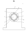
- FIG. 1 is a front view in which a part of a roll apparatus 1 according to an embodiment of the present invention is omitted and a part thereof is shown in cross section.
- FIG. 2 is a side view of the roll apparatus 1 shown in FIG.
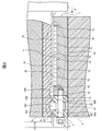
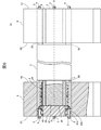
- FIG. 3 is an enlarged view of part A of the roll apparatus 1 shown in FIG.
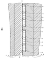
- FIG. 4 is an enlarged view of part B of the roll apparatus 1 shown in FIG. 3, and is a diagram schematically showing a state in which the radial load of the roll 2 is supported by the radial bearing 7.
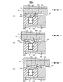
- 5 (A) to 5 (C) are enlarged views of part C of the roll apparatus 1 shown in FIG. 3, and are diagrams schematically showing a state in which the thrust bearing 8 supports the load in the thrust direction of the roll 2.
- FIG. 6 is a view showing a modified example 1a of the roll apparatus 1 shown in FIG.
- FIG. 1 is a front view in which a part of the roll apparatus 1 according to the present embodiment is omitted and a part thereof is shown in cross section
- FIG. 2 is a side view of the roll apparatus 1 shown in FIG.
- FIG. 3 is an enlarged view of part A of the roll apparatus 1 shown in FIG.
- a roll apparatus 1 includes a pair of shafts connected to a roll 2 for conveying an object to be conveyed such as a tape, a sheet, and a film, and both end faces 20 of the roll 2. 3, a pair of collars 4 attached to each of the pair of shafts 3, a pair of bearing units 5 that support each of the pair of collars 4 in a non-contact manner, and a pair of bearing units 5 that hold each of the pair of bearing units 5 And a housing 6.
- the shaft 3 is formed integrally with the roll 2 so as to protrude from both end faces 20 of the roll 2 on the same rotational axis O as the roll 2.
- the collar 4 is a magnetic body such as iron having a cylindrical shape, and the shaft 3 is inserted and fixed to the shaft 3 with a bolt, an adhesive, etc. (not shown).
- two annular grooves 42 a and 42 b are provided along the circumferential direction of the collar 4 on one end surface (an end surface opposite to the end surface facing the end surface 20 of the roll 2) 41. Is formed.
- an annular convex portion 43 a along the circumferential direction of the collar 4 is formed by being sandwiched between one end surface 41 of the collar 4 and the annular groove 42 a.
- an annular convex portion 43b along the circumferential direction of the collar 4 is formed by being sandwiched between the two annular grooves 42a and 42b.
- the bearing unit 5 includes a radial bearing 7 that supports the radial load of the collar 4 in which the shaft 3 connected to the roll 2 is inserted in a non-contact manner, and a thrust load (force) of the collar 4 in a non-contact manner. And a thrust bearing 8 to be supported.
- the radial bearing 7 has a cylindrical radial bearing body 70 and a porous sintered layer 72 provided on the inner peripheral surface 71 side of the radial bearing body 70.
- the inner diameter r1 of the radial bearing body 70 is twice the thickness of the compressed gas film L so that the compressed gas film L is formed between the outer peripheral surface 40 of the collar 4 and the inner peripheral surface 71 of the radial bearing body 70.
- the outer diameter r2 of the collar 4 is set larger.
- the thrust bearing 8 is fixed to one end surface 73 of the radial bearing main body 70 with a bolt 9 on one end surface (end surface opposite to the end surface facing the end surface 20 of the roll 2) 73 of the radial bearing main body 70.
- a plurality of screw holes 74 are formed.
- the porous sintered layer 72 is connected to an air passage 75 formed on the inner peripheral surface 71 of the radial bearing body 70, and compressed gas supplied from a pump (not shown) through the air passage 75 is porous. It is uniformly discharged from the surface of the porous sintered layer 72 (the inner peripheral surface 71 of the radial bearing body 70) through a large number of fine holes in the sintered layer 72.
- the thrust bearing 8 includes a pair of yokes 80a and 80b (hereinafter also simply referred to as a yoke 80) made of a magnetic material such as iron, and a plurality of magnets 81 disposed between the yokes 80a and 80b.
- a yoke 80 made of a magnetic material such as iron
- magnets 81 disposed between the yokes 80a and 80b.
- the yoke 80 is an annular magnetic body having substantially the same inner diameter and outer diameter as the inner diameter r1 and outer diameter r3 of the radial bearing body 70.
- the yoke 80 is coaxial with the radial bearing body 70 and has one end face 73 of the radial bearing body 70. Are attached with bolts 9. For this reason, the yoke 80 is formed with bolt insertion holes 82 for inserting the bolts 9 at positions corresponding to the screw holes 74 formed in the one end surface 73 of the radial bearing body 70.
- the magnet 81 is a permanent magnet such as neodymium, and is disposed between the pair of yokes 80 at equal intervals along the circumferential direction of the yoke 80.
- at least one yoke 80 may be provided with a recess for housing the magnet 81 on the surface facing the other yoke 80.
- an annular magnet may be arranged instead of arranging the plurality of magnets 81 between the pair of yokes 80.
- the housing 6 has a through hole 60 for holding the bearing unit 5 penetrating from one surface 61 to the other surface 62.
- the bearing unit 5 is inserted into the through hole 60 of the housing 6 and fixed to the through hole 60 of the housing 6 with a bolt, an adhesive, or the like (not shown).
- FIG. 4 is an enlarged view of part B of the roll device 1 shown in FIG. 3, and is a diagram schematically showing a state of supporting the radial load of the roll 2 by the radial bearing 7.
- the roll apparatus 1 when compressed gas is supplied from a pump (not shown) to the air passage 75 formed in the radial bearing body 70 of the radial bearing 7, the surface of the porous sintered layer 72.
- the compressed gas a is uniformly ejected from the (inner peripheral surface 71 of the radial bearing body 70), whereby a compressed gas film L is formed in the gap between the outer peripheral surface 40 of the collar 4 and the inner peripheral surface 71 of the radial bearing body 70. Is done.
- the compressed gas film L supports the radial load of the collar 4 in which the shaft 3 connected to the roll 2 is inserted in a non-contact manner.
- FIG. 5 (A) to 5 (C) are enlarged views of part C of the roll apparatus 1 shown in FIG. 3, and are diagrams schematically showing a state of supporting the load in the thrust direction of the roll 2 by the thrust bearing 8.
- the bolt 9, the bolt insertion hole 82, and the screw hole 74 are omitted for easy understanding of the state of the magnetic force.
- the pair of yokes 80a and 80b are made of a magnetic material, they are magnetized by the magnet 81 sandwiched between the yokes 80a and 80b to generate a magnetic force. Further, since the collar 4 is also made of a magnetic material, it is attracted by the magnetic force generated from the yokes 80a and 80b.
- two annular grooves 42a and 42b are formed in the outer peripheral surface 40 of the collar 4, and the inner periphery of each of the yokes 80a and 80b is formed by one end surface 41 of the collar 4 and these annular grooves 42a and 42b.
- annular convex portions 43a and 43b along the circumferential direction of the collar 4 are formed.
- the collar 4 has annular protrusions 43a and 43b formed on the outer circumferential surface 40 of the collar 4 in the thrust direction ⁇ T, respectively, and the inner circumferences of the yokes 80a and 80b.
- the collar 4 into which the shaft 3 connected to the roll 2 is inserted is made of a magnetic material, and the annular protrusions 43 a and 43 b are formed on the outer peripheral surface 40 of the collar 4.
- An annular thrust bearing 8 that generates a magnetic force is provided, and the collar 4 is inserted into the thrust bearing 8. Then, the magnetic force generated by the thrust bearing 8 attracts the annular protrusions 43a and 43b provided on the collar 4 to the inside of the thrust bearing 8, thereby supporting the load in the thrust direction of the collar 4 in a non-contact manner.
- an air supply path for supplying compressed gas to the thrust bearing gap and an exhaust path for discharging compressed gas supplied to the thrust bearing gap to the outside are provided. There is no need to provide it. Further, there is no need to provide a thrust bearing surface for ejecting compressed gas. For this reason, the roll apparatus which supports a roll by non-contact with a compact and simple structure can be provided.
- the roll device 1 by using a magnetic material for the collar 4 in which the shaft 3 connected to the roll 2 is inserted, an annular convex portion 43 a on the outer peripheral surface 40 of the collar 4, 43b is provided, it is not necessary to configure the shaft 3 with a magnetic material in order to support the load in the thrust direction by the thrust bearing 8. Therefore, the cost can be reduced and the degree of design freedom of the shaft 3 can be improved. it can.
- the annular grooves 42 a and 42 b are formed on the outer peripheral surface 40 of the collar 4 along the circumferential direction of the collar 4, so that one of the annular groove 42 a and the collar 4 is formed. Since the annular convex portions 43a and 43b are formed between the end surface 41 and between the annular groove 42a and the annular groove 42b, the relative position of the collar 4 in the thrust direction with respect to the thrust bearing 8 is determined. Can be easily constructed.
- the pair of annular yokes 80a and 80b having an inner diameter r1 larger than the outer diameter r2 of the collar 4 is made of a magnetic material such as iron, and these yokes 80a,
- the thrust bearing 8 is configured by sandwiching a plurality of magnets 81 such as neodymium between 80b. Therefore, compared with the case where the thrust bearing is configured using an annular magnet having an inner diameter larger than that of the pair of annular yokes 80a and 80b having the inner diameter r1, the amount of use of the magnet can be greatly reduced. Thereby, cost can be reduced.
- annular magnetic body may be attached to the shaft 3, and the annular protrusions 43 a and 43 b may be provided on the outer peripheral surface of the shaft 3.
- the cylindrical magnetic body 45 is bolted with a bolt, an adhesive or the like so that one end face 47 of the cylindrical magnetic body 45 faces the end face 30 of the shaft 3.
- the annular convex portions 43 a and 43 b may be formed on the outer peripheral surface 46 of the columnar magnetic body 45 by attaching to the third end surface 30.
- the shaft 3 is made of a magnetic material, the annular convex portions 43 a and 43 b may be directly formed on the outer peripheral surface of the shaft 3. In these cases, the collar 4 may be omitted.
- the pair of annular yokes 80a and 80b having an inner diameter r1 larger than the outer diameter r2 of the collar 4 is made of a magnetic material such as iron, and between the yokes 80a and 80b.
- the thrust bearing 8 is configured by sandwiching a plurality of magnets 81 such as neodymium, but the present invention is not limited to this.
- the thrust bearing 8 may have any configuration as long as it can generate a magnetic force with respect to the outer peripheral surface 40 of the collar 4.
- the magnet used is not limited to a permanent magnet, and may be an electromagnet.
- the radial bearing 7 is described in which the porous sintered layer 72 is formed on the inner peripheral surface 71 side of the radial bearing body 70, but the present invention is not limited to this.
- the inner peripheral surface 71 of the radial bearing body 70 may be formed with a self-formed throttle or an orifice throttle connected to the air passage 75 in the radial bearing body 70.
- the radial load of the collar 4 is supported using the radial bearing (air bearing) 7 using compressed gas.
- the load in the radial direction of the collar 4 may also be supported in a non-contact manner by using a magnetic force generated from the thrust bearing 8 toward the outer peripheral surface 40 of the collar 4.
Landscapes
- Engineering & Computer Science (AREA)
- General Engineering & Computer Science (AREA)
- Mechanical Engineering (AREA)
- Chemical & Material Sciences (AREA)
- Dispersion Chemistry (AREA)
- Magnetic Bearings And Hydrostatic Bearings (AREA)
- Rolls And Other Rotary Bodies (AREA)
Applications Claiming Priority (2)
| Application Number | Priority Date | Filing Date | Title |
|---|---|---|---|
| JP2014-033481 | 2014-02-24 | ||
| JP2014033481A JP2015158244A (ja) | 2014-02-24 | 2014-02-24 | ロール装置 |
Publications (1)
| Publication Number | Publication Date |
|---|---|
| WO2015125958A1 true WO2015125958A1 (ja) | 2015-08-27 |
Family
ID=53878454
Family Applications (1)
| Application Number | Title | Priority Date | Filing Date |
|---|---|---|---|
| PCT/JP2015/055015 Ceased WO2015125958A1 (ja) | 2014-02-24 | 2015-02-23 | ロール装置 |
Country Status (3)
| Country | Link |
|---|---|
| JP (1) | JP2015158244A (enExample) |
| TW (1) | TW201600749A (enExample) |
| WO (1) | WO2015125958A1 (enExample) |
Cited By (1)
| Publication number | Priority date | Publication date | Assignee | Title |
|---|---|---|---|---|
| US11994169B2 (en) | 2022-08-22 | 2024-05-28 | International Business Machines Corporation | Guide roller having magnets and bushings to stabilize a roller barrel for a tape medium |
Families Citing this family (1)
| Publication number | Priority date | Publication date | Assignee | Title |
|---|---|---|---|---|
| CN107289005A (zh) * | 2016-03-31 | 2017-10-24 | 曹阳 | 一种带状态监测的预载荷多孔气悬浮轴承 |
Citations (7)
| Publication number | Priority date | Publication date | Assignee | Title |
|---|---|---|---|---|
| JPH02229915A (ja) * | 1989-02-28 | 1990-09-12 | Tokyo Electric Co Ltd | 軸受装置 |
| JPH0338420U (enExample) * | 1989-08-24 | 1991-04-15 | ||
| JPH04248016A (ja) * | 1991-01-09 | 1992-09-03 | Nippon Seiko Kk | 磁気制御軸受ユニット |
| JPH08135670A (ja) * | 1994-11-10 | 1996-05-31 | Fuji Xerox Co Ltd | 軸受装置 |
| JPH11190336A (ja) * | 1997-12-25 | 1999-07-13 | Ntn Corp | 静圧軸受支持のガイドローラ |
| JP2002039177A (ja) * | 2000-07-24 | 2002-02-06 | Ntn Corp | 非接触軸受スピンドル装置 |
| JP2011085223A (ja) * | 2009-10-16 | 2011-04-28 | Hokkaido Univ | 3軸能動制御型磁気軸受及びこれを用いた回転機 |
Family Cites Families (2)
| Publication number | Priority date | Publication date | Assignee | Title |
|---|---|---|---|---|
| JP5724184B2 (ja) * | 2010-02-26 | 2015-05-27 | オイレス工業株式会社 | カムフォロア |
| JP5835766B2 (ja) * | 2010-02-26 | 2015-12-24 | オイレス工業株式会社 | ロール装置 |
-
2014
- 2014-02-24 JP JP2014033481A patent/JP2015158244A/ja active Pending
-
2015
- 2015-02-16 TW TW104105338A patent/TW201600749A/zh unknown
- 2015-02-23 WO PCT/JP2015/055015 patent/WO2015125958A1/ja not_active Ceased
Patent Citations (7)
| Publication number | Priority date | Publication date | Assignee | Title |
|---|---|---|---|---|
| JPH02229915A (ja) * | 1989-02-28 | 1990-09-12 | Tokyo Electric Co Ltd | 軸受装置 |
| JPH0338420U (enExample) * | 1989-08-24 | 1991-04-15 | ||
| JPH04248016A (ja) * | 1991-01-09 | 1992-09-03 | Nippon Seiko Kk | 磁気制御軸受ユニット |
| JPH08135670A (ja) * | 1994-11-10 | 1996-05-31 | Fuji Xerox Co Ltd | 軸受装置 |
| JPH11190336A (ja) * | 1997-12-25 | 1999-07-13 | Ntn Corp | 静圧軸受支持のガイドローラ |
| JP2002039177A (ja) * | 2000-07-24 | 2002-02-06 | Ntn Corp | 非接触軸受スピンドル装置 |
| JP2011085223A (ja) * | 2009-10-16 | 2011-04-28 | Hokkaido Univ | 3軸能動制御型磁気軸受及びこれを用いた回転機 |
Cited By (1)
| Publication number | Priority date | Publication date | Assignee | Title |
|---|---|---|---|---|
| US11994169B2 (en) | 2022-08-22 | 2024-05-28 | International Business Machines Corporation | Guide roller having magnets and bushings to stabilize a roller barrel for a tape medium |
Also Published As
| Publication number | Publication date |
|---|---|
| TW201600749A (zh) | 2016-01-01 |
| JP2015158244A (ja) | 2015-09-03 |
Similar Documents
| Publication | Publication Date | Title |
|---|---|---|
| US20240277998A1 (en) | Rotor bearing system | |
| US20150037128A1 (en) | Monolithic magnets with magnetic field domains for diamagnetic levitation | |
| US20100201216A1 (en) | Bearing device for non-contacting bearing of a rotor with respect to a stator | |
| CN104670949B (zh) | 一种用于柔性薄膜卷绕工艺的双驱动精密胀轴 | |
| WO2015125958A1 (ja) | ロール装置 | |
| JPWO2015174306A1 (ja) | 磁性流体シールの組立方法及び磁性流体シール | |
| KR101809104B1 (ko) | 자기베어링 및 영구자석부가 구비된 롤러모듈 | |
| KR101491675B1 (ko) | 롤 장치 | |
| JP7123899B2 (ja) | シール装置 | |
| JPH11190336A (ja) | 静圧軸受支持のガイドローラ | |
| WO2013077172A1 (ja) | 静圧気体軸受構造 | |
| JP2015158244A5 (enExample) | ||
| WO2013061813A1 (ja) | エアロールユニット | |
| WO2005039019A1 (ja) | アクチュエータ | |
| US20150377362A1 (en) | Sealed Bearing Assembly | |
| JP2010190397A (ja) | タッチダウン軸受 | |
| TWI642808B (zh) | 基板傳輸單元與鍍膜設備 | |
| WO2015016275A1 (ja) | 静圧気体軸受装置 | |
| JP2018155356A (ja) | カムフォロア | |
| KR102232174B1 (ko) | 고속 회전용 마그넷 커플링 회전 조립체 | |
| JPWO2006098500A1 (ja) | 磁気装置 | |
| JP2015025559A5 (enExample) | ||
| JP5962738B2 (ja) | ロール装置 | |
| JP2017213502A (ja) | 表面処理装置 | |
| JP2012072853A (ja) | カムフォロア |
Legal Events
| Date | Code | Title | Description |
|---|---|---|---|
| 121 | Ep: the epo has been informed by wipo that ep was designated in this application |
Ref document number: 15751464 Country of ref document: EP Kind code of ref document: A1 |
|
| NENP | Non-entry into the national phase |
Ref country code: DE |
|
| 122 | Ep: pct application non-entry in european phase |
Ref document number: 15751464 Country of ref document: EP Kind code of ref document: A1 |