WO2015125813A1 - 積層フィルム及びフィルム貼り付け方法 - Google Patents
積層フィルム及びフィルム貼り付け方法 Download PDFInfo
- Publication number
- WO2015125813A1 WO2015125813A1 PCT/JP2015/054404 JP2015054404W WO2015125813A1 WO 2015125813 A1 WO2015125813 A1 WO 2015125813A1 JP 2015054404 W JP2015054404 W JP 2015054404W WO 2015125813 A1 WO2015125813 A1 WO 2015125813A1
- Authority
- WO
- WIPO (PCT)
- Prior art keywords
- film
- base material
- adhesive layer
- foreign matter
- attaching
- Prior art date
- Legal status (The legal status is an assumption and is not a legal conclusion. Google has not performed a legal analysis and makes no representation as to the accuracy of the status listed.)
- Ceased
Links
Images






Classifications
-
- B—PERFORMING OPERATIONS; TRANSPORTING
- B32—LAYERED PRODUCTS
- B32B—LAYERED PRODUCTS, i.e. PRODUCTS BUILT-UP OF STRATA OF FLAT OR NON-FLAT, e.g. CELLULAR OR HONEYCOMB, FORM
- B32B7/00—Layered products characterised by the relation between layers; Layered products characterised by the relative orientation of features between layers, or by the relative values of a measurable parameter between layers, i.e. products comprising layers having different physical, chemical or physicochemical properties; Layered products characterised by the interconnection of layers
- B32B7/04—Interconnection of layers
- B32B7/12—Interconnection of layers using interposed adhesives or interposed materials with bonding properties
-
- B—PERFORMING OPERATIONS; TRANSPORTING
- B32—LAYERED PRODUCTS
- B32B—LAYERED PRODUCTS, i.e. PRODUCTS BUILT-UP OF STRATA OF FLAT OR NON-FLAT, e.g. CELLULAR OR HONEYCOMB, FORM
- B32B37/00—Methods or apparatus for laminating, e.g. by curing or by ultrasonic bonding
- B32B37/0007—Methods or apparatus for laminating, e.g. by curing or by ultrasonic bonding involving treatment or provisions in order to avoid deformation or air inclusion, e.g. to improve surface quality
- B32B37/003—Methods or apparatus for laminating, e.g. by curing or by ultrasonic bonding involving treatment or provisions in order to avoid deformation or air inclusion, e.g. to improve surface quality to avoid air inclusion
-
- B—PERFORMING OPERATIONS; TRANSPORTING
- B32—LAYERED PRODUCTS
- B32B—LAYERED PRODUCTS, i.e. PRODUCTS BUILT-UP OF STRATA OF FLAT OR NON-FLAT, e.g. CELLULAR OR HONEYCOMB, FORM
- B32B38/00—Ancillary operations in connection with laminating processes
- B32B38/10—Removing layers, or parts of layers, mechanically or chemically
-
- B—PERFORMING OPERATIONS; TRANSPORTING
- B32—LAYERED PRODUCTS
- B32B—LAYERED PRODUCTS, i.e. PRODUCTS BUILT-UP OF STRATA OF FLAT OR NON-FLAT, e.g. CELLULAR OR HONEYCOMB, FORM
- B32B38/00—Ancillary operations in connection with laminating processes
- B32B38/16—Drying; Softening; Cleaning
- B32B38/162—Cleaning
-
- B—PERFORMING OPERATIONS; TRANSPORTING
- B32—LAYERED PRODUCTS
- B32B—LAYERED PRODUCTS, i.e. PRODUCTS BUILT-UP OF STRATA OF FLAT OR NON-FLAT, e.g. CELLULAR OR HONEYCOMB, FORM
- B32B2307/00—Properties of the layers or laminate
- B32B2307/40—Properties of the layers or laminate having particular optical properties
-
- B—PERFORMING OPERATIONS; TRANSPORTING
- B32—LAYERED PRODUCTS
- B32B—LAYERED PRODUCTS, i.e. PRODUCTS BUILT-UP OF STRATA OF FLAT OR NON-FLAT, e.g. CELLULAR OR HONEYCOMB, FORM
- B32B2307/00—Properties of the layers or laminate
- B32B2307/40—Properties of the layers or laminate having particular optical properties
- B32B2307/402—Coloured
-
- B—PERFORMING OPERATIONS; TRANSPORTING
- B32—LAYERED PRODUCTS
- B32B—LAYERED PRODUCTS, i.e. PRODUCTS BUILT-UP OF STRATA OF FLAT OR NON-FLAT, e.g. CELLULAR OR HONEYCOMB, FORM
- B32B2457/00—Electrical equipment
- B32B2457/20—Displays, e.g. liquid crystal displays, plasma displays
Definitions
- the present invention relates to a laminated film and a film attaching method. More specifically, a laminated film suitable for attaching to the surface of a mobile display device such as a mobile phone or a tablet PC, and a film suitable for attaching such a laminated film on the user side such as homes and mass retailers. It relates to the pasting method.
- Mobile display devices such as mobile phones and tablet PCs are likely to be damaged by hitting or scratching them.
- the user himself / herself manually attaches a protective film to the surface of the mobile display device.
- the film is attached in a general indoor environment that is not a controlled environment such as in a clean room or vacuum.
- Patent Document 2 discloses a method of supplying a liquid having a temperature higher than room temperature and removing foreign matter and dirt on the surface of the liquid crystal panel.
- Patent Document 3 discloses a sticking device that automatically cleans the surface of a liquid crystal panel body before sticking a polarizing plate by a foreign matter cleaning roller.
- Patent Document 4 discloses a foreign matter removing pressure-sensitive adhesive tape that removes foreign matter adhering to the surface of a semiconductor wafer, a glass substrate or the like by adsorbing it to the adhesive layer surface.
- Patent Document 5 discloses a foreign matter removing sheet that is used by being attached to a conveying member, in which a separator for protecting the surface of the foreign matter removing layer is attached to the foreign matter removing layer by an adhesive layer. Yes.
- Patent Document 7 A laminated structure having a configuration is disclosed in Patent Document 7. That is, in Patent Document 7, a long body with a pattern structure layer in which a long body is attached to one surface of a pattern layer film via an adhesive layer and a release film is attached to the other surface via an adhesive layer. A scale is disclosed.
- Patent Document 1 In the technique of Patent Document 1, a vacuum chamber is used. In the technique of Patent Document 2, a liquid having a temperature higher than room temperature is used. The technique of Patent Document 3 is premised on automation of processing by a pasting apparatus. Patent Documents 4 and 5 only disclose that foreign matters are removed by an adhesive tape or sheet for removing foreign matters. After the adhesive tape or sheet for removing foreign matters is peeled off, foreign matter and bubbles are prevented from entering. There is no disclosure of how to attach a film to a product while preventing it. The techniques of Patent Documents 6 and 7 do not prevent foreign matter existing around the film from entering the pasting surface when the film is pasted.
- FIG. 17 is a schematic cross-sectional view showing a conventional method for attaching a laminated film.
- the procedure of bonding of the conventional laminated film will be described.
- (A) of FIG. 17 has shown the state of the base material 100 before bonding a laminated
- a general indoor environment that is not a controlled environment such as in a clean room or vacuum
- a large number of minute foreign substances 200 such as dust are floating. For this reason, the foreign material 200 adheres to the surface of the substrate 100.
- FIG. 17B shows a state of alignment of the conventional laminated film before being attached.
- the conventional laminated film shown in FIG. 17B has a configuration in which a separator film 211 is disposed on the lower surface of an optical film 217 via an adhesive layer 216.
- the separator film 211 is peeled off to expose the adhesive layer 216. Since the surface of the adhesive layer 216 exhibits adhesiveness, the foreign substance 200 floating in the indoor environment is likely to adhere.
- the optical film 217 is bonded to the base material 100 by bringing the adhesive layer 216 into close contact with the surface of the base material 100 by the bonding roller 241.
- the foreign matter 200 adheres to the surface of the base material 100 or the adhesive layer 216, the foreign matter 200 enters between the base material 100 and the optical film 217.
- air bubbles may enter between the substrate 100 and the optical film 217.
- the base material 100 is a screen of a display device, a portion where bubbles enter may appear as a white point, or a portion where foreign matter may enter may serve as a lens, which makes it difficult to see the screen display of the display device. . For this reason, there has been a demand for a method for attaching a laminated film that can prevent foreign substances and bubbles from entering even under a general indoor environment.
- the present invention has been made in view of the above situation, and foreign matter and air bubbles invade the pasting surface even when it is pasted manually in a general indoor environment where foreign matter such as dust floats. It is an object of the present invention to provide a laminated film that can be prevented from being easily used by general users and a film attaching method using the same.
- the present inventor does not require special environmental management or equipment at the time of pasting, and a functional film and a film that can prevent intrusion of foreign matters and bubbles even when pasted manually in a general indoor environment
- a functional film and a film that can prevent intrusion of foreign matters and bubbles even when pasted manually in a general indoor environment
- many foreign substances such as dust are floating in the air, and even if the foreign substances on the base material to which the functional film is pasted are once removed.
- the inventors paid attention to the fact that foreign matter adheres to the substrate and the adhesive surface of the functional film until immediately before the functional film is attached. Therefore, the present inventor removes the foreign matter on the base material immediately before attaching the functional film, and immediately after that, if the laminated film incorporates the foreign matter removal film capable of cleaning on the base material.
- one embodiment of the present invention includes a surface protective film, a foreign matter removing pressure-sensitive adhesive layer, a foreign matter removing film, a base material sticking pressure-sensitive adhesive layer, and a functional film in this order.
- the adhesive layer for attaching may be a laminated film having stronger bonding strength with the functional film than bonding strength with the foreign matter removing film.
- Another aspect of the present invention includes a surface protective film, a foreign matter removing adhesive layer, a foreign matter removing film, a base material sticking adhesive layer, and a functional film in this order.
- the adhesive force of the adhesive layer for attaching may be a laminated film that is stronger than the adhesive force of the adhesive layer for removing foreign matter.
- Yet another embodiment of the present invention is a film attaching method for attaching a functional film contained in the laminated film of the present invention to a substrate, comprising the following steps (1) to (5):
- a film sticking method may be used.
- (1) The surface protective film is peeled off from the laminated film to expose the foreign matter removing adhesive layer.
- (2) The exposed foreign matter removing adhesive layer is brought into close contact with the surface of the base material.
- the adhesive layer for adhering the base material is peeled off from the film for removing foreign matter while the base material and the functional film are connected by the connecting member.
- the adhesive for removing foreign matter from the surface of the base material While peeling the layer and exposing the surface of the base material, the adhesive layer for attaching the base material is adhered to the exposed surface of the substrate, and the functional film is attached to the base material.
- the laminated film of the present invention even if foreign matter such as dust is present on the base material, the foreign matter on the base material is removed immediately before the functional film is attached, and then the functional film is immediately Therefore, it is possible to sufficiently prevent foreign matters and bubbles from entering the bonding interface.
- no special environmental management or equipment is required for bonding, and no liquid is used, so that it is easy for general users to use.
- the film sticking method of the present invention is based on the functional film without using the laminated film of the present invention so that foreign matter and air bubbles are mixed into the bonding interface even in a general indoor environment. Can be attached to the material. Further, unlike the conventional laminating method using soapy water, since it is a dry laminating method that does not use liquid, the working time can be greatly shortened and the work can be performed without soiling the periphery.
- FIG. 1 is a schematic cross-sectional view showing a laminated film according to Embodiment 1.
- FIG. It is a cross-sectional schematic diagram for demonstrating the method to affix the laminated film which concerns on Embodiment 1 on a base material. It is the schematic diagram which showed an example of the mechanism for affixing the laminated
- FIG. It is the cross-sectional schematic diagram which showed an example of the sticking jig
- FIG. 6 is a schematic cross-sectional view showing a configuration of a liquid crystal display device of Embodiment 4.
- FIG. It is a side surface schematic diagram explaining the structure of the bonding jig
- 1 is a schematic cross-sectional view showing a laminated film according to Example 1.
- FIG. It is the cross-sectional schematic diagram which showed the pasting method of the conventional laminated
- each “film” is not limited by its thickness, and may be a “sheet”.
- the value of the adhesive strength of the adhesive layer varies depending on the object to be applied and the measurement method, but in this specification, when evaluating the value of the adhesive strength of the adhesive layer, no alkali is used regardless of the actual object to be applied. A substrate made of glass is used as an object to be pasted, and a value obtained by the following measurement method is used. However, when evaluating the value of the adhesive strength of the pressure-sensitive adhesive layer with respect to the surface subjected to the easy peeling treatment, a substrate made of non-alkali glass having the same easy peeling treatment applied to the surface is used. In addition, although the absolute value of adhesive force changes with sticking objects, there exists a tendency for the magnitude relationship of adhesive force not to change.
- a film with a strip-like adhesive layer having a width of 25 mm is stuck on a horizontally fixed substrate. At this time, one end of the film is not attached to the substrate. One end of the film not attached to the substrate is sandwiched by a chuck of a tensile tester (peeling test jig), and a 90-degree peeling test (a tensile speed of 0.3 m / min) is performed.
- FIG. 1 is a schematic cross-sectional view showing a laminated film according to the first embodiment.
- the laminated film 20 according to Embodiment 1 includes a separator film (surface protective film) 11, a foreign matter removing adhesive layer 12, a foreign matter removing film 13, a base material attaching adhesive layer 16, and an optical film (functionality). Film) 17 and the structure provided in order.
- the optical film 17 is positioned on the uppermost part of the laminated film 20 when being attached to the base material.
- the adhesion layer and the surface protection film may be laminated
- the separator film 11 protects the surface of the foreign matter removing pressure-sensitive adhesive layer 12 before use. It does not specifically limit as the separator film 11,
- common films such as a PET (polyethylene terephthalate) film, a PEN (polyethylene naphthalate) film, an acrylic film, a COP (cycloolefin polymer) film, can be used.
- the foreign matter removing pressure-sensitive adhesive layer 12 is for adsorbing foreign matters on the surface of the base material to be bonded, and it is preferable that the adhesive force is much weaker than the base material sticking pressure-sensitive adhesive layer 16. .
- pressure-sensitive adhesive materials classified as slightly sticky are suitable. Specifically, PF-AN422, PF-AN474 (above, manufactured by Lintec), ZBO-0421 (Fujimori Kogyo) Etc.).
- the adhesive strength of the foreign matter removing adhesive layer 12 is preferably 0.05 to 1 N / 25 mm width. When the width is less than 0.05 N / 25 mm, the adherend is easily peeled off, and workability is deteriorated. When the width exceeds 1 N / 25 mm, the adhesive strength may be stronger than that of the adhesive layer 16 for attaching a base material, and the first separator film 11 is difficult to peel off.
- the foreign matter removing film 13 is for supporting the foreign matter removing pressure-sensitive adhesive layer 12.
- the foreign matter removing pressure-sensitive adhesive layer 12 and the foreign matter removing film 13 are integrally handled, and the sticking and peeling of the foreign matter removing film 13 mean simultaneously sticking and peeling of the foreign matter removing pressure-sensitive adhesive layer 12.
- the foreign matter removing film 13 is not particularly limited, and for example, a general film such as a PET (polyethylene terephthalate) film, a PEN (polyethylene naphthalate) film, an acrylic film, or a COP (cycloolefin polymer) film can be used.
- the foreign matter removing film 13 may be colored.
- the adhesive layer 16 for attaching the base material is an adhesive layer for attaching the optical film 17 to the base material, and also has a role of integrating the film 13 for removing foreign matter and the optical film 17 in the laminated film 20. .
- the adhesive layer 16 for attaching the base material and the optical film 17 are handled integrally, and the attaching and peeling of the optical film 17 mean the attaching and peeling of the adhesive layer 16 for attaching the base material at the same time.
- the material for the adhesive layer 16 for attaching the base material a material that adheres firmly to the base material is suitable. Specifically, MO3014 (manufactured by Fujimori Kogyo Co., Ltd.), MCF-464, NCF-619 (hereinafter, Lintec) Etc.).
- the adhesive strength of the adhesive layer 16 for adhering the base material is stronger than that of the adhesive layer for removing foreign matter, and specifically, it is preferably 1 to 30 N / 25 mm width.
- the width is less than 1 N / 25 mm, the adhesiveness of the foreign substance removing adhesive layer 12 as the lower layer is smaller than that of the lower layer, so that workability is deteriorated when the first separator film 11 is peeled off.
- it exceeds 30 N / 25 mm width it is difficult to peel off the adherend, and workability deteriorates.
- the surface of the foreign substance removing film 13 on the side of the adhesive layer 16 for adhering to the base material is subjected to an easy peeling treatment. Therefore, the adhesive layer 16 for adhering the base material is bonded to the film 13 for removing foreign substances.
- the bonding strength with the optical film 17 is stronger than the strength.
- the optical film 17 is not particularly limited as long as it is a film having an optical function, and examples thereof include an antireflection film, an antiglare film, and a retardation film.
- the structure of the optical film 17 is not particularly limited, and may have a concavo-convex shape on the surface or a laminated structure. Examples of the structure (projection) that forms the uneven shape include a conical nanostructure.
- a moth-eye film having a moth-eye (brown eye) -like surface structure can be mentioned.
- Specific examples of the optical film 17 having a laminated structure include DBEF series manufactured by Sumitomo 3M.
- Examples of the material of the optical film 17 include PET (polyethylene terephthalate), PEN (polyethylene naphthalate), acrylic, and COP (cycloolefin polymer).
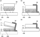
- FIG. 2 is a schematic cross-sectional view for explaining a method for affixing the laminate film according to Embodiment 1 onto a substrate.
- FIG. 2 the procedure of laminating
- the alignment laminated film 20 and the base material 100 are aligned. At this time, one side of the end portion of the laminated film 20 may be attached to the base material 100 with a connecting member such as the tape 30, and the laminated film 20 may be fixed to the base material 100.
- the surface of the base material 100 may be cleaned before the laminated film 20 is attached. Note that, except in an environment where foreign matter is artificially removed such as in a clean room or in a vacuum, the foreign matter 200 such as dust is usually floating in the air, and as shown in FIG.
- the foreign material 200 is also attached to the surface of the base material 100 to be bonded.
- the kind of base material 100 is not specifically limited, For example, a glass plate and a resin film are mentioned.
- the tape 30 is attached to the end of the optical film 17 at the top of the laminated film 20. Further, it is desirable that the exposed adhesive layer 12 for removing foreign substances is sequentially pressed with a roller while the separator film 11 is peeled off, and is adhered to the substrate 100. As a result, air bubbles can be prevented from entering between the surface of the base material 100 and the foreign matter removing pressure-sensitive adhesive layer 12, so that the foreign matter 200 can be appropriately removed from the entire surface of the base material 100.
- the foreign substance removing film 13 can be peeled by inserting the drawer bar into the region between the substrate 100 and the optical film 17 and attaching the drawer bar to the foreign substance removing film 13 and then pulling out the drawer bar.
- rod what equips the front-end
- the foreign matter 200 on the base material 100 is removed, and the surface of the base material 100 is exposed in a clean state. And in order to prevent a foreign material from entering a bonding interface, immediately after the surface of the base material 100 is exposed, the adhesive layer 16 for base material sticking is stuck.
- the foreign matter removing pressure-sensitive adhesive layer 12 is peeled off by winding the foreign matter removing film 13 with a take-up roller. It is preferable that the adhesion of the adhesive layer 16 for adhering the base material is performed by pressing with a sticking roller.
- the speed at which the foreign matter removing film 13 is peeled off (film winding speed) and the moving speed of the laminating roller (film bonding speed) are the same. It is preferable. From the viewpoint of continuously attaching the optical film 17, the speed at which the foreign matter removing film 13 is peeled off may be the same as or faster than the moving speed of the laminating roller 41.
- the optical film 17 since the optical film 17 is bonded with the tape 30 fixed thereto, the optical film 17 can be bonded to the region where the foreign matter 200 has been accurately removed. Further, since the region from which the foreign matter 200 has been removed is covered with the optical film 17 immediately after the foreign matter removing film 13 is peeled off, the foreign matter 200 such as dust may adhere from the surroundings before the optical film 17 is attached. Is prevented.
- the adhesive layer 16 for attaching the base material is not directed upward. For this reason, when peeling off the base material-adhering adhesive layer 16 from the foreign matter removing film 13, the optical film 17 is pulled in a direction that forms an angle of 0 ° or more and less than 90 ° with respect to the base material 100. Is preferred. Further, since it is easy to quickly peel off the foreign matter removing film 13 before the optical film 17 is attached, the time for exposing the adhesive layer 16 for attaching the base material is shortened, and the adhesive for attaching the base material is used. The foreign matter 200 can be sufficiently prevented from adhering to the layer 16.
- the optical film 17 can be attached to the base material 100 without the foreign matter 200 and air bubbles entering the bonding interface even in a general indoor environment. Further, unlike the conventional laminating method using soapy water, since it is a dry laminating method that does not use liquid, the working time can be greatly shortened and the work can be performed without soiling the periphery.
- FIG. 3 is a schematic diagram illustrating an example of a mechanism for attaching the laminated film according to the first embodiment.
- the foreign matter removing film 13 is wound up by rotating the peeling roller 43 and peeled off from the substrate 100.
- the optical film 17 is bonded to the substrate 100 by moving the bonding rollers 41 and 42 toward the foreign matter removing film 13 while rotating them.
- the rotation speed of the peeling roller 43 is set to be equal or faster than the rotation speed of the bonding rollers 41 and 42.
- the arrangement of the peeling roller 43 is preferably set to a minimum height that does not contact the base material 100 in order to avoid contact with the optical film 17.
- Tension is applied to the optical film 17 by a mechanism that applies tension such as a spring or a torque motor.
- the angle with respect to the base material 100 in the direction in which the optical film 17 is pulled is larger than the angle with respect to the base material 100 in the direction in which the foreign matter removing film 13 is peeled off, and small enough that the optical film 17 does not wind around the laminating roller 41. Is done.
- the angle at which the optical film 17 is pulled is preferably smaller than the vertical direction with respect to the substrate 100.
- the foreign matter removing film 13 and the optical film 17 may be provided with a pulling lead portion.
- the lead portion is a portion that extends from the main body portion of each of the films 13 and 17 and is made thinner than the main body portion. By providing the lead portion, it becomes easy to apply a uniform tension when the films 13 and 17 are pulled, so that the workability can be improved and the accuracy of bonding the optical film 17 can be improved.
- the lead portion may be a portion formed integrally with the main body portion of each film 13, 17, or may be a tape member (lead tape) attached to the main body portion of each film 13, 17. .
- FIG. 4 is a schematic cross-sectional view showing an example of a bonding jig suitable for the bonding mechanism of FIG.
- peeling by winding the foreign matter removing film 13 and sticking of the optical film 17 are performed in parallel.
- the sticking jig shown in FIG. Can also be implemented.
- a characteristic configuration of the attaching jig shown in FIG. 4 will be described below. 4, the roller A corresponds to the bonding roller 41 in FIG. 3, and the roller C corresponds to the peeling roller 43.
- rollers A, B, and C each have a rotation shaft fixed to the side plate 51. Therefore, the rollers A, B, and C can be moved at the same speed with respect to the base material 100 even manually.
- the rollers A, B, and C are preferably connected to each other by a belt, a chain, or the like. Roller A is the same size as roller C.
- the roller A is a free rotating roller.
- the rotation axis of the roller A is connected to the cover 52 via the spring 53 and is suspended from the cover 52.
- the cover 52 is lifted, and the roller A is arranged above the base material 100 so that a gap with the base material 100 is opened.
- the roller A is pressed against the optical film 17 by a method such as manually pressing the cover 52 from above.
- the roller B is a brake roller, and can feed the wound film when a certain tension is applied.
- the auxiliary tape having the maximum length for attachment is first wound, and the end (lead portion) of the optical film 17 is connected to the end of the auxiliary tape.
- the roller B is provided with a mechanism that regulates the rotation of the roller in one direction, such as a cam structure, and applies an initial tension by turning the roller B.
- the initial tension is preferably applied after the end of the optical film 17 is brought into contact with the substrate 100.
- the roller C is a brake roller that is connected to the roller A as described above and has a brake mechanism attached to the shaft of the roller so that a constant tension is applied to the torque.
- the roller C is attached to the foreign matter removing film 13 and applied with tension.
- the auxiliary tape wound around the roller C is bonded to the tensile portion (the right side in FIG. 4) of the foreign matter removing film 13.
- the roller C also includes a mechanism that regulates rotation of the roller in one direction.
- the cover 52 is made of a transparent body or a part thereof.
- the cover 52 and the side plate 51 are connected to each other by pins, whereby the cover 52 is fixed with respect to the side plate 51 in a rotation-free state.
- the cover 52 is configured to be detachable from the main body portion of the attaching jig. That is, the cover 52 can be easily separated from and integrated with the side plate 51 and the rollers A, B, and C. Therefore, the work may be performed by removing the cover 52 from the attaching jig as necessary.
- a hole may be formed in the cover 52, and a gas that does not contain foreign matter such as nitrogen gas may be introduced from the hole. If pasting is performed while introducing gas from the hole of the cover 52, it is possible to more effectively prevent foreign matter from entering the bonding interface.
- FIG. 5 is a schematic plan view showing an example of a sticking apparatus provided with the sticking jig of FIG.
- the base material 100 is fixed, and the attaching jig 106 in FIG. 4 is moved along the guide rail 103.
- the optical film 17 can be attached with high accuracy. It can be suitably used when the base material 100 to which the optical film 17 is attached is a small-sized material such as a portable device.
- the base material 100 is placed on a fixed base 102 on the table 107 and fixed.
- the affixing jig 106 is connected to a slider 104 that moves on the guide rail 103 via a connecting jig 105 so that the affixing jig 106 can move along the guide rail 103.
- the end of the fixed base 102 and the guide rail 103 are arranged in parallel, and the connection jig 105 is arranged at a right angle with respect to the guide rail 103.
- the connecting jig 105 and the attaching jig 106 can move linearly in a direction parallel to the guide rail 103.
- Only one guide rail 103 may be provided, or two guide rails 103 may be provided on both sides of the fixed base 102 as shown in FIG.
- FIG. 6 is a schematic cross-sectional view for explaining a method of attaching an optical film with the attaching device of FIG.
- the base material 100 is fixed on the fixing base 102, the laminated film 20 is placed thereon, and the laminated film 20 is placed on the base material by the laminating roller 41 that is a part of the attaching jig 106.
- the optical film 17 can be bonded.
- Embodiment 3 demonstrates the case where a functional film is affixed with respect to the base material which has a level
- the substrate having a step on the surface include a display device including a frame portion (outer frame) around the display portion.
- a display device including a frame portion (outer frame) around the display portion.
- there is a step at the boundary between the display unit and the frame unit there are cases in which all four sides of the rectangular display unit are steps.
- there are many steps in medium to large display devices such as notebook computer screens, monitors, and televisions. As shown in FIG.
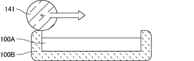
- the bonding roller 141 is used for a base material that has no step between the upper surface of the display unit (which may be a front plate) 100A and the upper surface of the frame unit 100B and has no unevenness on the surface. It is easy to affix the laminated film of Embodiment 1 by pressing down with. However, as shown in FIG. 8, when a protrusion exists on the outer periphery of the base material, the height of the protrusion on the outer periphery becomes larger than the thickness of the laminated film to be pressed in the sheet configuration of the laminated film of Embodiment 1.
- FIG. 7 is an explanatory diagram showing affixing of the laminated film to a substrate having no irregularities on the surface
- FIG. 8 is an explanatory diagram showing affixing of the laminated film to a substrate having irregularities on the surface.
- the laminated film of the third embodiment has a substrate pasting pressure-sensitive adhesive layer 16 of the optical film (functional film) 17 of the first embodiment in order to affix a functional film to a substrate having an uneven surface.
- a cushion layer (buffer layer) made of an elastic body is provided on the side opposite to the contacting side.
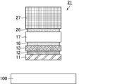
- FIG. 9 is a schematic cross-sectional view illustrating an example of a laminated film including the cushion layer according to Embodiment 3
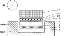
- FIG. 10 is a schematic cross-sectional view illustrating another example of the laminated film including the cushion layer according to Embodiment 3.
- FIG. The laminated film 21 in FIG. 9 has a configuration in which a cushion layer 27 is directly laminated on one surface of the optical film 17 via an adhesive layer 26.
- a separator film 29 is laminated on one surface of the optical film 17 via an adhesive layer 28, and a cushion is provided on the opposite side of the separator film 29 from the adhesive layer 28 via an adhesive layer 26.
- the layer 27 has a stacked structure.
- the cushion layer 27 preferably has flexibility and a hardness that can maintain the film shape when peeled.
- a foam of a resin material is suitable, and as the resin material, a urethane resin, a butadiene resin, or the like is suitably used.
- urethane foam (trade name: nipper lay, 5 mm thickness) manufactured by Nihon Hojo Co., Ltd. can be used.
- the thickness of the cushion layer 27 is appropriately set according to the level of the step existing on the surface of the base material.
- the cushion layer 27 is positioned at the upper end (base material) of the frame portion 100B. It is preferable to protrude from the upper end of the step on the surface. That is, the laminated film is not stuck to the base material 100 by the foreign matter removing adhesive layer 12 shown in FIG. 11, but the foreign matter removing adhesive layer 12 is peeled off from the surface of the base material 100 and the base material is attached.
- the pressure-sensitive adhesive layer 16 is brought into close contact and the optical film 17 shown in FIG.
- FIG. 11 is an explanatory diagram illustrating a state in which the laminated film is bonded to the base material by the foreign matter removing adhesive layer
- FIG. 12 is an explanatory diagram illustrating a state in which the optical film is bonded to the base material. .
- the cushion layer 27 is designed to protrude from the upper end of the frame portion 100B when the optical film 17 is bonded to the base material 100.
- the cushion layer 27 is usually designed to be the thickest when compared to the adhesive layer 16 for attaching a base material, the optical film 17, the adhesive layer 26, the adhesive layer 28, and the separator film 29.
- the cushion layer 27 is about 0.5 mm to 10 mm. Is set.
- the material of the adhesive layers 26 and 28 it is preferable to use an adhesive material suitable for an optical material.
- the layers below the optical film 17 and in the form of FIG. 10 the layers below the separator film 29 are cut according to the size of the affixing portion of the base material 100, and the paste margin considering the misalignment.
- the cushion layer 27 cut slightly smaller than the size of each of the above layers is pasted together while leaving Although the roll of the product becomes large, the cushion layer 27 may be cut at the same time after being produced by roll-to-roll.
- a bonding experiment was conducted using a display (manufactured by Sharp Corporation: monitor display LL-171G-W). Cutting of the film such as the optical film 17 was 3 mm inside from the surroundings. The level difference between the frame portion 100B and the display was about 2 mm. At the time of bonding, the laminated film protruded above the outer frame of about +3.5 mm. When a pressure was applied by the bonding roller, the pressure was transmitted to the optical film 17 through the cushion layer 27, so that the foreign film was not mixed, and there was no unevenness due to insufficient bonding pressure and no inclusion of bubbles.
- Embodiment 4 an example of a display device in which a frame portion (outer frame) forms a step will be described by exemplifying a liquid crystal display device.
- FIG. 13 is a schematic cross-sectional view showing a general configuration of a conventional liquid crystal display device.
- a step is formed at the boundary between the display surface of the liquid crystal panel 300 and the frame portion 100 ⁇ / b> B.
- the optical film 302A laminated via the plate 301 is made larger than the opening part of the frame part 100B opened corresponding to the image display area of the liquid crystal panel 300, and the end surface of the optical film 302A is the frame part 100B. It is designed not to be located in the opening. In such a configuration, it is necessary to remove the frame part 100B when replacing the optical film 302A, and it may be necessary to destroy the frame part 100B.
- FIG. 14 is a schematic cross-sectional view showing the configuration of the liquid crystal display device of the fourth embodiment.
- a step with a height of, for example, 0.1 to 20 mm is formed between the top of the protruding portion of the frame portion 100B and the surface of the liquid crystal panel 300.
- the width of the opening portion of the frame portion 100B is defined as A
- the width of the optical film 302B disposed in the opening portion is defined as B
- the liquid crystal panel 300 satisfies the relationship of AB> 0.
- An optical film 302B is disposed on the outermost surface. With such a configuration, the optical film 302B can be replaced without removing the outer frame 100B.
- a low reflection film such as a film having a moth-eye structure, an anti-glare (AG) film, a polarizing plate, a circular polarizing plate, an antifouling film, a hard coat (HC) film, a SAM film, or any other optical In the film, the reattachment can be simplified.
- liquid crystal display device is exemplified as the display device of the fourth embodiment
- a thin display device such as an organic EL display device (OLED) or a MEMS (Micro Electro-Mechanical System) shutter type display device is used. (FDP) or a display device with a touch panel may be used.
- OLED organic EL display device
- MEMS Micro Electro-Mechanical System
- FDP Display Device with a touch panel
- the shape of the optical film 302B in plan view is generally preferably a rectangle having substantially the same shape as the display area, but even if there is a handle portion for peeling off by hand for replacement.
- the handle portion can be formed by providing a protruding portion on a part of the long side or the short side of the portion (display portion) corresponding to the display area of the optical film 302B.
- a protruding portion As the shape of the protruding portion, a rectangular shape, a square shape, a semicircular shape, a trapezoid shape, or a shape obtained by rounding these corners can be used.
- the dent line may be a straight line or an intermittent dotted line.
- Embodiment 5 demonstrates the film sticking method in case the sticking surface of a base material is a curved surface.
- a weak adhesive layer made of a silicon-based slightly adhesive material is generally used.
- this silicon-based weakly adhesive layer is weak in adhesiveness (adhesion), it is in a close contact state when air is pushed out from the interface, and is particularly suitable for application to a flat glass plate.
- peeling occurs at the end due to the elastic force of the film.
- peeling occurs even when it is attached to the surface of a polymer (resin material), the surface of an uneven surface (for example, an AG film), or the like.
- the adhesive strength of the adhesive material is reduced on a hydrophobic surface with many weak C—H bonds. Since the slightly adhesive material is designed to have a low adhesion force, a slight decrease in adhesion force leads to peeling. On the uneven surface, the amount of deformation of the slightly adhesive material is small and cannot follow the unevenness, so that bubbles are easily drawn and stress starts to be peeled off from the peripheral portion.
- the laminated film of the present invention it is possible to use a strong adhesive layer for attaching a functional film while preventing foreign matters from being mixed. Therefore, the laminated film of the present invention can be attached to a curved surface.
- FIG. 15 is a schematic side view illustrating the configuration of a jig for bonding to a curved substrate.
- the bonding jig has a structure in which a curved surface bonding roll 142 and a columnar support drum 143 are arranged to face each other.
- the curved surface bonding roll 142 is coupled to an elastic body such as a spring or a piston, and is driven up and down (in the direction of the arrow in FIG. 15) with a constant pressure.
- a curved substrate 144 such as a curved display to which a film is attached is disposed.
- the support drum 143 is selected according to the curvature of the curved substrate 144, but the curved bonding roll 142 is separated from the drive system and is free in the rotation direction, or both of them can be adjusted using an adjustment jig. The difference in curvature may be eliminated.
- the film is attached by passing a laminated film including the foreign substance removing film 13 and the optical film 17 between the curved bonding roll 142 and the support drum 143 in a state where the curved substrate 144 is disposed on the support drum 143. Is done.
- the curvature of the support drum 143 and the curved substrate 144 is 30 mm (phi) or more.
- the film after bonding may peel that the said curvature is less than 30 mmphi.
- a strong pressure-sensitive adhesive manufactured by Lintec Corporation, MO3014
- TAC triacetyl cellulose
- Example 1 As Example 1, an example of actually manufacturing the laminated film according to Embodiment 1 is shown. 16 is a schematic cross-sectional view showing the laminated film of Example 1. FIG. The laminated film of Example 1 has the configuration shown in FIG. 16, and the material and thickness of each layer are as follows.
- Separator film 11 PET film, thickness 38 ⁇ m Foreign matter removing adhesive layer 12: manufactured by Fujimori Kogyo Co., Ltd., (trade name) ZBO-0421, thickness 21 ⁇ m Foreign matter removing film 13: PET film, thickness 38 ⁇ m Adhesive layer 16 for substrate pasting: manufactured by Lintec Corporation, (trade name) MO3014, thickness 50 ⁇ m Optical film 17: moth-eye film, thickness 70 ⁇ m Adhesive layer 31: adhesive for moth-eye film (manufactured by Lintec), thickness 25 ⁇ m Protective film 33: PET film, thickness 100 ⁇ m
- PET film is slightly inferior in optical properties compared to PEN film and COP film, but it is excellent in mechanical strength and industrially mass-produced, so it is particularly suitable for films that do not require much optical properties.
- Yes. (Characteristics of PET film) Tensile strength: 200-290MPs Transmittance: 89% Haze: 2-3% (Characteristics of PEN film) Tensile strength: 200-290MPs Transmittance: 89% Haze: 2-3% (Characteristics of COP film) Tensile strength: 60-80MPs Transmittance: 92% Haze: 0.1% or less
- the moth-eye film is a laminate having an upper layer portion made of an acrylate-based photocurable resin and a lower layer portion made of triacetyl cellulose (TAC). On the surface of the upper layer portion, protrusions with a height of 200 nm are provided at intervals of 200 nm, and the surface structure has a moth-eye shape.
- TAC triacetyl cellulose
- the material of the film for the optical element is selected according to the application, but a TAC film having a high transmittance (transmittance of 92%) is preferable. In order to improve water resistance and heat resistance, a COP film or the like may be used.
- the adhesive strength of each layer in the laminated film of Example 1 was as follows.
- the value of adhesive force was measured with the following measuring methods, using the board
- the value of the adhesive strength of the base material sticking adhesive layer 16 is the same as that of the same. It measured using the board
- the unit of adhesive strength is N / 25 mm width.
- the value of adhesive force was shown by the range.
- a film with a strip-like adhesive layer having a width of 25 mm was pasted on a horizontally fixed substrate. At this time, one end of the film was not attached to the substrate. One end that was not attached to the substrate was sandwiched by a chuck of a tensile tester (peeling test jig), and a 90 degree peel test (pulling rate 0.3 m / min) was performed.
- the adhesive strength is in the order of the foreign matter removing adhesive layer 12 ⁇ the base material attaching adhesive layer 16. Moreover, since workability
- the adhesive layer 16 for attaching the base material had a stronger bonding strength with the optical film 17 than the bonding strength with the foreign matter removing film 13.
- the optical film is exemplified as the functional film.
- the type of the functional film is not particularly limited.
- the protective film used for uses such as a building material and a showcase other than the optical film and protective film which are affixed on the surface of display apparatuses, such as a portable apparatus, a decoration film etc. are mentioned, for example.
- Examples of the optical film suitable for the present invention include the following films (1) to (7), and two or more of the following films (1) to (7) may be used in combination. In addition, it is preferable to apply this invention to a functional film with an expensive functional film with a bad yield.
- the antireflection film include a film having a moth-eye structure and a film formed by laminating thin films having a low refractive index.
- a film with a moth-eye structure has a structure in which a plurality of protrusions are arranged at a pitch and height of 100 nm to several hundreds of nanometers, and prevents the interface reflection by continuously changing the refractive index at the interface with the air layer. The function to perform is demonstrated.
- Examples of the water / oil repellent film include a film obtained by solubilizing a fluorine polymer, coating and drying, and a film made of a siloxane material in which molecules having fluorine side chains are chemically bonded to the surface of a substrate by a reactive group. And a film having a low surface tension surface obtained by polymerizing a fluorine-based monomer or oligomer.
- Commercially available products include, for example, soluble fluoropolymer Cytop (Asahi Glass Co., Ltd.), fluorosurf release agent (Fluorosurf Co., Ltd.) and the like.
- SAM film A wide viewing angle film that diffuses light traveling straight in all directions with a fine wedge-shaped slope structure.
- the processing yield can be improved by laminating in a film touch panel roll shape and dividing the film after the application of the adhesive is completed. This is because an appropriate strength can be obtained by thickening the film at the time of bonding. In particular, when it is attached to a large-sized display device such as for signage, the yield improvement effect is great.
- optical films for film building materials that cannot be used in clean rooms scattering prevention film, heat ray cut film, antifouling film, antiglare (AG) film, scratch resistant film, antifogging film, etc.
- the film structure or the film attaching method of the present invention is used, it is not necessary to use water, and foreign matter can be sufficiently prevented even outside the clean room.
- Thin glass (especially front plate) The processing yield can be improved by laminating the film in a roll form and dividing the film after the adhesive coating is completed. At the time of bonding, an appropriate strength can be obtained by increasing the thickness of the film, which makes it difficult to break.
- the foreign matter removing film is subjected to a surface treatment for reducing the bonding strength with the base material sticking adhesive layer at the interface in contact with the base material sticking adhesive layer.
- a surface treatment for reducing the bonding strength with the base material sticking adhesive layer at the interface in contact with the base material sticking adhesive layer. Examples of the surface treatment include coating.
- the foreign matter removing film is preferably colored.
- the functional film is preferably an optical film.
- the optical film include a film having a moth-eye structure.
- the functional film is preferably a protective film.
- the functional film may serve as an optical film and a protective film.
- the laminated film may further have a buffer layer on the side of the functional film opposite to the side in contact with the adhesive layer for attaching the base material.
- the adhesive layer for adhering the substrate is removed from the film for removing foreign matter by pulling the functional film in a direction that forms an angle of 0 ° or more and less than 90 ° with respect to the substrate. Peeling is preferable. The fewer the formation of V-shaped gaps due to the lifting of the functional film, the less the possibility of contamination.
- the foreign matter removing pressure-sensitive adhesive layer is peeled off by winding the foreign matter removing film with a take-up roller, and the base material sticking pressure-sensitive adhesive layer is adhered to the sticking roller. Is preferably performed by pressing.
- the winding speed of the foreign matter removing film is preferably the same as or faster than the attaching speed of the functional film.
- the base material has a curved surface shape.
- the base material is disposed on a support drum having a columnar shape, and the bonding roller disposed to face the support drum and the above
- the laminated film may be attached to the substrate by passing the laminated film between the support drum and the support drum.
- Still another aspect of the present invention is a display panel having an image display region, an optical film disposed on the outermost surface of the display panel, and an outer frame having a portion protruding from the outermost surface of the display panel.
- the optical film covers the image display area, and the outer frame may be a display device having an opening that exposes the entire area where the optical film is disposed.
Landscapes
- Engineering & Computer Science (AREA)
- Mechanical Engineering (AREA)
- Quality & Reliability (AREA)
- Laminated Bodies (AREA)
- Cleaning In General (AREA)
- Liquid Crystal (AREA)
Abstract
Description
(1)上記積層フィルムから上記表面保護フィルムを剥離し、上記異物除去用粘着層を露出させる
(2)露出した上記異物除去用粘着層を上記基材の表面に密着させ、上記基材に対して上記積層フィルムを貼り付ける
(3)上記基材の上記積層フィルムが貼り付けられた領域の近傍と、上記積層フィルムの最上部の上記機能性フィルムの端部とを接続部材で接続する
(4)上記接続部材によって上記基材と上記機能性フィルムとを接続したまま、上記基材貼り付け用粘着層を上記異物除去用フィルムから剥離する
(5)上記基材の表面から上記異物除去用粘着層を剥離し、上記基材の表面を露出させつつ、露出した上記基板の表面に、上記基材貼り付け用粘着層を密着させ、上記基材に対して上記機能性フィルムを貼り付ける
本明細書において、各「フィルム」は、その厚さによって限定されるものではなく、「シート」と呼ばれるものであってもよい。
(粘着力の測定方法)
水平に固定した基板上に、幅25mmの短冊状の粘着層付きのフィルムを貼り付ける。このとき、フィルムの一端は基板に貼り付けないようにする。引っ張り試験機(剥離試験治具)のチャックによって基板に貼り付けなかったフィルムの一端を挟み、90度剥離試験(引張り速度0.3m/min)を行う。
(1)積層フィルムの構成
図1は、実施形態1に係る積層フィルムを示した断面模式図である。実施形態1に係る積層フィルム20は、セパレーターフィルム(表面保護フィルム)11と、異物除去用粘着層12と、異物除去用フィルム13と、基材貼り付け用粘着層16と、光学フィルム(機能性フィルム)17と、が順に設けられた構成を有する。基材への貼り付け時には、光学フィルム17が積層フィルム20の最上部に位置する。なお、光学フィルム17の基材貼り付け用粘着層16が設けられていない側の表面上に、粘着層、及び、表面保護フィルムが積層されていてもよい。
図2は、実施形態1に係る積層フィルムを基材上に貼り付ける方法を説明するための断面模式図である。以下、図2に基づき、実施形態1に係る積層フィルムの貼り合わせの手順を説明する。
積層フィルム20と基材100との位置合わせを行う。この時点で、積層フィルム20の端部の一辺を、テープ30等の接続部材によって基材100に貼り付け、積層フィルム20を基材100に対して固定してもよい。基材100上に比較的大きな異物がある場合や、汚れが付着している場合には、積層フィルム20の貼り付け前に基材100の表面を清掃してもよい。なお、クリーンルーム中又は真空中のように人工的に異物が除去された環境以外では、通常、埃等の異物200が空気中に浮遊しており、図2の(a)に示したように、貼り合わせ対象となる基材100の表面にも異物200が付着している。基材100の種類は特に限定されず、例えば、ガラス板、樹脂フィルムが挙げられる。
セパレーターフィルム11を剥離し、異物除去用粘着層12を露出させる。その状態で、図2の(b)に示したように、積層フィルム20を基材100に貼り付ける。これによって、異物除去用粘着層12と基材100の表面とが密着し、基材100の表面に付着していた異物200が異物除去用粘着層12に吸着される。上記(1)位置合わせの時点でテープ30による固定を実施していないときには、積層フィルム20の端部の一辺を、基材100の積層フィルム20が貼り付けられた領域の近傍にテープ30によって貼り付け、積層フィルム20を基材100に対して固定する。テープ30は、積層フィルム20の最上部にある光学フィルム17の端部に貼り付けられる。また、セパレーターフィルム11を剥離しながら、露出した異物除去用粘着層12を順次ローラーで押しつけ、基材100への貼り付けを行うことが望ましい。これによって、基材100の表面と異物除去用粘着層12との間に気泡が入ることを防止できるので、基材100の表面全体から異物200を適切に除去することができる。
異物除去用フィルム13上を押さえた状態で、光学フィルム17を上方に引き上げることにより、図2の(c)に示したように、異物除去用フィルム13と光学フィルム17とを引き剥がす。これによって、積層フィルム20は、V字状に開いた状態になる。このとき、基材貼り付け用粘着層16は、光学フィルム17側にある。
異物除去用フィルム13の端部をテープ30から剥がす。次に、異物除去用フィルム13のテープ30側の端部を、基材100と光学フィルム17の間の領域から引っ張り出しつつ、貼り合わせローラーによって、基材100に光学フィルム17を順次押しつける。これによって、基材100と基材貼り付け用粘着層16とが密着し、図2の(d)に示したように、基材100の表面に、基材貼り付け用粘着層16を介して、光学フィルム17が貼り付けられる。異物除去用フィルム13を引っ張り出す際には引き出し棒を用いてもよい。この場合、基材100と光学フィルム17の間の領域に引き出し棒を差し込み、引き出し棒を異物除去用フィルム13に取り付けた後に、引き出し棒を引き抜くことで異物除去用フィルム13を剥離できる。引き出し棒としては、粘着部材(例えば、両面テープ)、フック(鉤部)等の取り付け手段を先端に備えるものが挙げられる。
最後に、テープ30を取り外せば、光学フィルム17の基材100への貼り付けが完了する。
実施形態2では、積層フィルムの貼り付けに関する機構及び治具の説明を行う。図3は、実施形態1に係る積層フィルムを貼り付けるための機構の一例を示した模式図である。図3に示したように、引き剥がしローラー43を回転させることによって異物除去用フィルム13を巻き取って基材100から引き剥がす。それと同時に、貼り合わせローラー41及び42を回転させながら異物除去用フィルム13の側へ移動させることによって、光学フィルム17を基材100に貼り付ける。このとき、引き剥がしローラー43の回転速度は、貼り合わせローラー41及び42の回転速度に対して、等速又はより速く設定される。また、引き剥がしローラー43の配置は、光学フィルム17との接触を避けるため、基材100に接しない最低限の高さにすることが好ましい。光学フィルム17には、ばね、トルクモータ等の張力(テンション)を付与する機構によってテンションが掛けられる。光学フィルム17を引っ張る方向の基材100に対する角度は、異物除去用フィルム13を引き剥がす方向の基材100に対する角度よりも大きくされ、かつ貼り合わせローラー41に光学フィルム17が巻き付かない程度に小さくされる。また、貼り付け前の光学フィルム17の下方に異物が入り込むことを防止する観点から、光学フィルム17を引っ張る角度は、基材100に対する鉛直方向よりも小さいことが好ましい。なお、貼り合わせローラー42を用いずに、平滑な表面を有する机、定盤等の平面で基材100を支持してもよい。
実施形態3では、表面に段差を有する基材に対して、機能性フィルムを貼り付ける場合について説明する。表面に段差を有する基材としては、表示部の周囲にフレーム部(外枠)を備える表示装置が挙げられる。このような表示装置では、表示部とフレーム部の境界に段差があり、矩形状の表示部の周囲4辺がいずれも段差となっている場合もある。特に、ノートパソコンの画面、モニター、テレビ等の中型~大型の表示装置において、段差が存在することが多い。図7に示したように、表示部(前面板であってもよい)100Aの上面とフレーム部100Bの上面との間に段差がなく、表面に凹凸がない基材については、貼り合わせローラー141で押さえつけることによって実施形態1の積層フィルムを貼り付けることは容易である。しかしながら、図8に示したように、基材の外周に出っ張りが存在すると、実施形態1の積層フィルムのシート構成では、押しつける積層フィルムの厚さよりも外周の出っ張りの高さの方が大きくなる。貼り合わせローラー141の幅は、一般的に、押しつける基材の幅よりも広いため、外周の出っ張りがあると、貼り合わせローラー141が当たり、ワークの表面を押さえつけることができずに、貼り付けがうまくいかない場合がある。図7は、表面に凹凸がない基材に対する積層フィルムの貼り付けを示した説明図であり、図8は、表面に凹凸がある基材に対する積層フィルムの貼り付けを示した説明図である。
実施形態4では、フレーム部(外枠)が段差を形成している表示装置の形態について、液晶表示装置を例示して説明する。
実施形態5では、基材の貼り付け面が曲面である場合のフィルム貼り付け方法について説明する。フィルムの貼り付けには、一般的にシリコン系微粘着材料からなる弱粘着層が使用される。このシリコン系の弱粘着層は、粘(接)着力が弱いものの、界面から空気を押し出すと密着状態となり、特に平坦なガラス板への貼り付けには適しているが、貼り付け面が曲面の場合には、フィルムの弾性力のために、端部で剥離が生じてしまう。また、高分子(樹脂材料)の表面や、凹凸表面を有するフィルム(例えば、AGフィルム)の表面等に貼り付けた場合にも、剥離が生じてしまう。樹脂材料の場合、弱いC-H結合の多い、ハイドロホービックな表面では、粘着材料の密着力が低下する。微粘着材料は、密着力が低い設計であるため、少しの密着力の低下が、剥離へとつながる。凹凸表面では、微粘着材料の変形量が少なく凹凸に追随できないため、気泡を引き込みやすくなり、応力の掛り易い、周辺部分から剥離が始まる。
実施例1として、実施形態1に係る積層フィルムを実際に製造した例を示す。図16は、実施例1の積層フィルムを示した断面模式図である。実施例1の積層フィルムは、図16に示した構成を有し、各層の材質及び厚さは、以下のとおりである。
セパレーターフィルム11:PETフィルム、厚さ38μm
異物除去用粘着層12:藤森工業社製、(商品名)ZBO-0421、厚さ21μm
異物除去用フィルム13:PETフィルム、厚さ38μm
基材貼り付け用粘着層16:リンテック社製、(商品名)MO3014、厚さ50μm
光学フィルム17:モスアイフィルム、厚さ70μm
粘着層31:モスアイフィルム用粘着剤(リンテック社製)、厚さ25μm
保護フィルム33:PETフィルム、厚さ100μm
(PETフィルムの特性)
引張り強度:200~290MPs
透過率:89%
ヘイズ:2~3%
(PENフィルムの特性)
引張り強度:200~290MPs
透過率:89%
ヘイズ:2~3%
(COPフィルムの特性)
引張り強度:60~80MPs
透過率:92%
ヘイズ:0.1%以下
異物除去用粘着層12(セパレーターフィルム11との界面):0.3~0.4
基材貼り付け用粘着層16(異物除去用フィルム13との界面):1~2
粘着層31(光学フィルム17との界面):0.1~0.2
水平に固定した基板上に、幅25mmの短冊状の粘着層付きのフィルムを貼り付けた。このとき、フィルムの一端は基板に貼り付けないようにした。引っ張り試験機(剥離試験治具)のチャックによって基板に貼り付けなかった一端を挟み、90度剥離試験(引張り速度0.3m/min)を行った。
(1)反射防止フィルム
反射防止フィルムとしては、モスアイ(蛾の目)構造を有するフィルム、低屈折率の薄膜を積層して形成されたフィルム等が挙げられる。モスアイ構造を有するフィルムは、複数の突起が100nm~数百nmのピッチ及び高さで配置された構造を有し、空気層との界面で屈折率を連続的に変化させることによって界面反射を防止する機能を発揮するものである。
(2)円偏光板
液晶パネルの表面に円偏光板を配置することで、外部から液晶パネルに入射して液晶パネルの内部で反射された光が、外部に出射することを防止できる。すなわち、表示画面における外光の映り込みを防止できる。その理由は、液晶パネル内部で反射された偏光は、位相差がλ/2変化することによって偏光状態が90度旋回し、円偏光板によって遮断されるためである。上記(1)の反射防止フィルムと組み合わせると、表面反射及び内部反射の両方を抑制でき、表示品位の向上に効果的である。
(3)防汚性、耐擦傷性改善フィルム
撥水撥油膜が塗布されたものが挙げられる。撥水撥油膜としては、例えば、フッ素ポリマーを可溶化して塗布乾燥して得られた膜、フッ素系側鎖を有する分子を反応基によって基板の表面に化学結合させたシロキサン系材料からなる膜、フッ素系のモノマー、オリゴマーを重合して得られる低表面張力の表面を有する膜が挙げられる。市販品としては、例えば、可溶性のフッ素ポリマーのサイトップ(旭硝子社製)、フッ素化合物の離型処理剤であるフロロサーフ(フロロサーフ社製)等が挙げられる。
(4)SAMフィルム
直進光を微細構造の楔状の斜面構造で、全方位に拡散させる広視野角フィルムである。
(5)フィルムタッチパネル
ロール状で貼り合わせ、粘着剤の塗工まで終わってからフィルムを分断することで、加工歩留まりを改善することができる。これは、貼り合わせの際に、フィルムが厚くなることで適度な強度が得られるためである。特に、サイネージ用のような大型サイズの表示装置に貼り付ける場合に、歩留りの改善効果が大きい。
(6)クリーンルームが使えない用途のフィルム
建材用の光学フィルム(飛散防止フィルム、熱線カットフィルム、防汚性フィルム、防眩(AG)フィルム、耐傷性フィルム、防曇フィルム等)については、現状は水洗して、水貼りで対応しているが、異物の混入が避けられず、また、水の使用による現場での養生の手間もかかる。本発明のフィルム構造又はフィルム貼り付け方法を用いれば、水の使用が不要であり、クリーンルーム外であっても、異物の混入を充分に防止できる。
(7)薄板ガラス(特に前面板)
ロール状で張り合わせ、粘着剤塗工まで終わってからフィルムを分断することで、加工歩留まりを改善することができる。貼り合せの際に、フィルムが厚くなることで適度な強度が得られるため、割れにくくなる。
以下に、本発明の積層フィルムの好ましい態様の例を挙げる。各例は、本発明の要旨を逸脱しない範囲において適宜組み合わされてもよい。
12:異物除去用粘着層
13:異物除去用フィルム
16:基材貼り付け用粘着層
17:光学フィルム
20、21、22:積層フィルム
26、28:粘着層
27:クッション層(緩衝層)
29:セパレーターフィルム
30:テープ
31:粘着層
33:保護フィルム
41、42、141、241:貼り合わせローラー
43:引き剥がしローラー
51:側板
52:カバー
53:バネ
100:基材
100A:表示部
100B:フレーム部(外枠)
102:固定台
103:ガイドレール
104:スライダー
105:接続治具
106:貼り付け治具
107:テーブル
142:曲面貼り合わせロール
143:支持ドラム
144:曲面基板
200:異物
211:セパレーターフィルム
216:粘着層
217:光学フィルム
A,B,C:ローラー
300:液晶パネル
301:偏光板
302A、302B:光学フィルム
Claims (14)
- 表面保護フィルムと、
異物除去用粘着層と、
異物除去用フィルムと、
基材貼り付け用粘着層と、
機能性フィルムと、を順に有し、
前記基材貼り付け用粘着層は、前記異物除去用フィルムとの接合強度よりも前記機能性フィルムとの接合強度が強い
ことを特徴とする積層フィルム。 - 前記異物除去用フィルムは、前記基材貼り付け用粘着層と接する界面に、前記基材貼り付け用粘着層との接合強度を低下させる表面処理がなされていることを特徴とする請求項1記載の積層フィルム。
- 表面保護フィルムと、
異物除去用粘着層と、
異物除去用フィルムと、
基材貼り付け用粘着層と、
機能性フィルムと、を順に有し、
前記基材貼り付け用粘着層の粘着力は、前記異物除去用粘着層の粘着力よりも強力である
ことを特徴とする積層フィルム。 - 前記異物除去用フィルムは、着色されていることを特徴とする請求項1~3のいずれかに記載の積層フィルム。
- 前記機能性フィルムは、光学フィルムであることを特徴とする請求項1~4のいずれかに記載の積層フィルム。
- 前記機能性フィルムは、保護フィルムであることを特徴とする請求項1~4のいずれかに記載の積層フィルム。
- 前記積層フィルムは、更に、前記機能性フィルムの前記基材貼り付け用粘着層と接する側とは反対側に、緩衝層を有することを特徴とする請求項1~6のいずれかに記載の積層フィルム。
- 請求項1~7のいずれかに記載の積層フィルムに含まれる機能性フィルムを、基材に対して貼り付けるフィルム貼り付け方法であって、
下記(1)~(5)の手順を含むことを特徴とするフィルム貼り付け方法。
(1)前記積層フィルムから前記表面保護フィルムを剥離し、前記異物除去用粘着層を露出させる
(2)露出した前記異物除去用粘着層を前記基材の表面に密着させ、前記基材に対して前記積層フィルムを貼り付ける
(3)前記基材の前記積層フィルムが貼り付けられた領域の近傍と、前記積層フィルムの最上部の前記機能性フィルムの端部とを接続部材で接続する
(4)前記接続部材によって前記基材と前記機能性フィルムとを接続したまま、前記基材貼り付け用粘着層を前記異物除去用フィルムから剥離する
(5)前記基材の表面から前記異物除去用粘着層を剥離し、前記基材の表面を露出させつつ、露出した前記基板の表面に、前記基材貼り付け用粘着層を密着させ、前記基材に対して前記機能性フィルムを貼り付ける - 前記手順(4)において、前記基材に対して0°以上、90°未満の角度を形成する方向に前記機能性フィルムを引っ張ることによって前記基材貼り付け用粘着層を前記異物除去用フィルムから剥離することを特徴とする請求項8記載のフィルム貼り付け方法。
- 前記手順(5)において、前記異物除去用粘着層の剥離は、前記異物除去用フィルムを巻き取りローラーにより巻き取ることによって行われ、かつ前記基材貼り付け用粘着層の密着は、貼り付けローラーにより押し当てることによって行われることを特徴とする請求項8又は9記載のフィルム貼り付け方法。
- 前記異物除去用フィルムの巻き取り速度は、前記機能性フィルムの貼り付け速度と同じ、又は、より速いことを特徴とする請求項10記載のフィルム貼り付け方法。
- 前記手順(5)において、先端に粘着部材が取り付けられた引き出し棒を用いることを特徴とする請求項8~11のいずれかに記載のフィルム貼り付け方法。
- 前記手順(5)において、先端に鉤部が設けられた引き出し棒を用いることを特徴とする請求項8~11のいずれかに記載のフィルム貼り付け方法。
- 前記基材は、曲面形状を有するものであり、
前記手順(2)において、円柱形状を有する支持ドラム上に前記基材を配置し、前記支持ドラムに対向して配置された貼り合わせローラーと前記支持ドラムとの間に、前記積層フィルムを通過させることよって、前記基材に対して前記積層フィルムを貼り付けることを特徴とする請求項8~13のいずれかに記載のフィルム貼り付け方法。
Priority Applications (3)
| Application Number | Priority Date | Filing Date | Title |
|---|---|---|---|
| US14/777,545 US10046543B2 (en) | 2014-02-18 | 2015-02-18 | Laminated film and film attachment method |
| CN201580000547.4A CN105121152A (zh) | 2014-02-18 | 2015-02-18 | 层叠膜和膜贴附方法 |
| JP2015532213A JP5856358B1 (ja) | 2014-02-18 | 2015-02-18 | 積層フィルム及びフィルム貼り付け方法 |
Applications Claiming Priority (2)
| Application Number | Priority Date | Filing Date | Title |
|---|---|---|---|
| JP2014028776 | 2014-02-18 | ||
| JP2014-028776 | 2014-02-18 |
Publications (1)
| Publication Number | Publication Date |
|---|---|
| WO2015125813A1 true WO2015125813A1 (ja) | 2015-08-27 |
Family
ID=53878313
Family Applications (1)
| Application Number | Title | Priority Date | Filing Date |
|---|---|---|---|
| PCT/JP2015/054404 Ceased WO2015125813A1 (ja) | 2014-02-18 | 2015-02-18 | 積層フィルム及びフィルム貼り付け方法 |
Country Status (4)
| Country | Link |
|---|---|
| US (1) | US10046543B2 (ja) |
| JP (1) | JP5856358B1 (ja) |
| CN (1) | CN105121152A (ja) |
| WO (1) | WO2015125813A1 (ja) |
Cited By (1)
| Publication number | Priority date | Publication date | Assignee | Title |
|---|---|---|---|---|
| JPWO2017002741A1 (ja) * | 2015-07-02 | 2018-06-07 | シャープ株式会社 | フィルム貼り付け器具、及び、フィルム貼り付けユニット |
Families Citing this family (4)
| Publication number | Priority date | Publication date | Assignee | Title |
|---|---|---|---|---|
| CN106381086A (zh) * | 2016-11-14 | 2017-02-08 | 绍兴市上虞区三口胶粘制品厂 | 粘尘纸及其生产工艺 |
| CN109624462A (zh) * | 2018-10-25 | 2019-04-16 | 惠州市浩明科技股份有限公司 | 抗静电保护膜 |
| JP2022020286A (ja) * | 2020-07-20 | 2022-02-01 | 株式会社ディスコ | 保護部材形成装置で用いるシート、及び保護部材形成方法 |
| CN114872315A (zh) * | 2022-06-13 | 2022-08-09 | 深圳市志凌伟业技术股份有限公司 | 一种应用于胶片保护的方法 |
Citations (4)
| Publication number | Priority date | Publication date | Assignee | Title |
|---|---|---|---|---|
| JP2003534954A (ja) * | 2000-05-30 | 2003-11-25 | ヴィー・エー・テー・オートモーティヴ・システムス・アクチェンゲゼルシャフト | 接合フィルム、その製造法およびその使用 |
| JP2005125526A (ja) * | 2003-10-21 | 2005-05-19 | Lintec Corp | キャスト製膜用工程フィルム |
| JP2007172241A (ja) * | 2005-12-21 | 2007-07-05 | Toshiba Corp | スクリーンフィルム |
| JP2014004834A (ja) * | 2012-06-22 | 2014-01-16 | Lg Electronics Inc | ミラー効果を有する外装フィルム及びその製造方法 |
Family Cites Families (11)
| Publication number | Priority date | Publication date | Assignee | Title |
|---|---|---|---|---|
| JPH07318919A (ja) | 1994-05-25 | 1995-12-08 | Casio Comput Co Ltd | 光学フィルムの貼り付け方法 |
| JPH0850290A (ja) | 1994-08-05 | 1996-02-20 | Casio Comput Co Ltd | 偏光板の貼付方法およびその装置 |
| JP3425267B2 (ja) | 1995-03-29 | 2003-07-14 | 日東電工株式会社 | 精密電子部品の異物除去用粘着テ―プ |
| JP2006119186A (ja) | 2004-10-19 | 2006-05-11 | Hitachi Maxell Ltd | 画面保護シート |
| JP4365312B2 (ja) | 2004-12-27 | 2009-11-18 | 日東電工株式会社 | 異物除去シート |
| JP3141815U (ja) * | 2008-01-18 | 2008-05-22 | 株式会社パワーサポート | 粘着セパレータ付き保護フィルム |
| CN201538078U (zh) * | 2009-05-13 | 2010-08-04 | 胡瑞根 | 无尘贴屏幕保护膜套装 |
| JP2010286664A (ja) | 2009-06-11 | 2010-12-24 | Sharp Corp | フィルム貼付け方法およびフィルム貼付け装置 |
| US11472098B2 (en) * | 2010-06-22 | 2022-10-18 | Zagg Inc | Protective layers for dry application to protected surfaces, installation assemblies and kits including the layers, devices protected with the layers, and associated methods |
| JP5750980B2 (ja) | 2011-04-12 | 2015-07-22 | 大日本印刷株式会社 | パターン構造層付き長尺体およびパターン構造層の貼り合せ方法 |
| CN203110429U (zh) * | 2013-02-20 | 2013-08-07 | 周德峰 | 屏幕保护膜 |
-
2015
- 2015-02-18 US US14/777,545 patent/US10046543B2/en active Active
- 2015-02-18 CN CN201580000547.4A patent/CN105121152A/zh active Pending
- 2015-02-18 JP JP2015532213A patent/JP5856358B1/ja not_active Expired - Fee Related
- 2015-02-18 WO PCT/JP2015/054404 patent/WO2015125813A1/ja not_active Ceased
Patent Citations (4)
| Publication number | Priority date | Publication date | Assignee | Title |
|---|---|---|---|---|
| JP2003534954A (ja) * | 2000-05-30 | 2003-11-25 | ヴィー・エー・テー・オートモーティヴ・システムス・アクチェンゲゼルシャフト | 接合フィルム、その製造法およびその使用 |
| JP2005125526A (ja) * | 2003-10-21 | 2005-05-19 | Lintec Corp | キャスト製膜用工程フィルム |
| JP2007172241A (ja) * | 2005-12-21 | 2007-07-05 | Toshiba Corp | スクリーンフィルム |
| JP2014004834A (ja) * | 2012-06-22 | 2014-01-16 | Lg Electronics Inc | ミラー効果を有する外装フィルム及びその製造方法 |
Cited By (1)
| Publication number | Priority date | Publication date | Assignee | Title |
|---|---|---|---|---|
| JPWO2017002741A1 (ja) * | 2015-07-02 | 2018-06-07 | シャープ株式会社 | フィルム貼り付け器具、及び、フィルム貼り付けユニット |
Also Published As
| Publication number | Publication date |
|---|---|
| US10046543B2 (en) | 2018-08-14 |
| US20160347032A1 (en) | 2016-12-01 |
| JPWO2015125813A1 (ja) | 2017-03-30 |
| JP5856358B1 (ja) | 2016-02-09 |
| CN105121152A (zh) | 2015-12-02 |
Similar Documents
| Publication | Publication Date | Title |
|---|---|---|
| JP6322278B2 (ja) | 積層フィルム及びフィルム貼り付け方法 | |
| JP6405045B2 (ja) | フィルム貼り付け方法 | |
| JP5856358B1 (ja) | 積層フィルム及びフィルム貼り付け方法 | |
| JP5167319B2 (ja) | 光学機能フィルム、及びこれを用いた液晶表示装置の製造方法 | |
| KR102436860B1 (ko) | 광학 필름 세트 및 그의 제조 방법 | |
| TW201903437A (zh) | 光學膜、剝離方法及光學顯示面板之製造方法 | |
| KR20160002889A (ko) | 광학 적층체 및 그것을 이용한 표시 장치 | |
| TW201922492A (zh) | 影像顯示裝置用積層體 | |
| JP2009237489A (ja) | 表面保護フィルム付き偏光板の製造方法 | |
| CN108885298A (zh) | 光学薄膜、剥离方法以及光学显示面板的制造方法 | |
| JP2017024262A (ja) | 透明な粘着剤層を有する導電性フィルム積層体 | |
| WO2016031978A1 (ja) | 基板の貼合装置及び積層体の製造方法並びに画像表示装置の製造方法 | |
| JP6480582B2 (ja) | フィルム貼り付け器具、及び、フィルム貼り付けユニット | |
| KR20090110635A (ko) | 양면 점착 시트, 이를 이용한 표시 장치 및 그 제조 방법 | |
| KR20160053949A (ko) | 광학용 점착 시트 및 그 제조 방법 | |
| TW201805701A (zh) | 光學顯示面板之製造方法與光學顯示面板之製造系統 | |
| JP2017187516A (ja) | 基板の貼合装置及び貼合方法並びに画像表示装置 | |
| US20150124382A1 (en) | Display device and method for producing same | |
| TW201823036A (zh) | 光學膜組件以及其用途 | |
| JP2016065910A (ja) | 基板の貼合装置及び貼合方法並びに画像表示装置 | |
| JP6562377B2 (ja) | 基板の貼合装置及び貼合方法 | |
| US11997810B2 (en) | Display device including a bonding member | |
| JP2016095331A (ja) | 基板の剥離装置及び剥離方法 | |
| WO2016031979A1 (ja) | 基板の貼合装置及び積層体の製造方法並びに画像表示装置の製造方法 |
Legal Events
| Date | Code | Title | Description |
|---|---|---|---|
| WWE | Wipo information: entry into national phase |
Ref document number: 201580000547.4 Country of ref document: CN |
|
| ENP | Entry into the national phase |
Ref document number: 2015532213 Country of ref document: JP Kind code of ref document: A |
|
| WWE | Wipo information: entry into national phase |
Ref document number: 14777545 Country of ref document: US |
|
| 121 | Ep: the epo has been informed by wipo that ep was designated in this application |
Ref document number: 15752278 Country of ref document: EP Kind code of ref document: A1 |
|
| NENP | Non-entry into the national phase |
Ref country code: DE |
|
| 122 | Ep: pct application non-entry in european phase |
Ref document number: 15752278 Country of ref document: EP Kind code of ref document: A1 |