WO2015122281A1 - バーナタイル、バーナ及び炉 - Google Patents
バーナタイル、バーナ及び炉 Download PDFInfo
- Publication number
- WO2015122281A1 WO2015122281A1 PCT/JP2015/052463 JP2015052463W WO2015122281A1 WO 2015122281 A1 WO2015122281 A1 WO 2015122281A1 JP 2015052463 W JP2015052463 W JP 2015052463W WO 2015122281 A1 WO2015122281 A1 WO 2015122281A1
- Authority
- WO
- WIPO (PCT)
- Prior art keywords
- burner tile
- burner
- inorganic fiber
- main hole
- inorganic
- Prior art date
Links
Images


Classifications
-
- F—MECHANICAL ENGINEERING; LIGHTING; HEATING; WEAPONS; BLASTING
- F23—COMBUSTION APPARATUS; COMBUSTION PROCESSES
- F23M—CASINGS, LININGS, WALLS OR DOORS SPECIALLY ADAPTED FOR COMBUSTION CHAMBERS, e.g. FIREBRIDGES; DEVICES FOR DEFLECTING AIR, FLAMES OR COMBUSTION PRODUCTS IN COMBUSTION CHAMBERS; SAFETY ARRANGEMENTS SPECIALLY ADAPTED FOR COMBUSTION APPARATUS; DETAILS OF COMBUSTION CHAMBERS, NOT OTHERWISE PROVIDED FOR
- F23M5/00—Casings; Linings; Walls
- F23M5/02—Casings; Linings; Walls characterised by the shape of the bricks or blocks used
- F23M5/025—Casings; Linings; Walls characterised by the shape of the bricks or blocks used specially adapted for burner openings
-
- B—PERFORMING OPERATIONS; TRANSPORTING
- B32—LAYERED PRODUCTS
- B32B—LAYERED PRODUCTS, i.e. PRODUCTS BUILT-UP OF STRATA OF FLAT OR NON-FLAT, e.g. CELLULAR OR HONEYCOMB, FORM
- B32B18/00—Layered products essentially comprising ceramics, e.g. refractory products
-
- C—CHEMISTRY; METALLURGY
- C04—CEMENTS; CONCRETE; ARTIFICIAL STONE; CERAMICS; REFRACTORIES
- C04B—LIME, MAGNESIA; SLAG; CEMENTS; COMPOSITIONS THEREOF, e.g. MORTARS, CONCRETE OR LIKE BUILDING MATERIALS; ARTIFICIAL STONE; CERAMICS; REFRACTORIES; TREATMENT OF NATURAL STONE
- C04B35/00—Shaped ceramic products characterised by their composition; Ceramics compositions; Processing powders of inorganic compounds preparatory to the manufacturing of ceramic products
- C04B35/01—Shaped ceramic products characterised by their composition; Ceramics compositions; Processing powders of inorganic compounds preparatory to the manufacturing of ceramic products based on oxide ceramics
- C04B35/10—Shaped ceramic products characterised by their composition; Ceramics compositions; Processing powders of inorganic compounds preparatory to the manufacturing of ceramic products based on oxide ceramics based on aluminium oxide
- C04B35/111—Fine ceramics
-
- C—CHEMISTRY; METALLURGY
- C04—CEMENTS; CONCRETE; ARTIFICIAL STONE; CERAMICS; REFRACTORIES
- C04B—LIME, MAGNESIA; SLAG; CEMENTS; COMPOSITIONS THEREOF, e.g. MORTARS, CONCRETE OR LIKE BUILDING MATERIALS; ARTIFICIAL STONE; CERAMICS; REFRACTORIES; TREATMENT OF NATURAL STONE
- C04B35/00—Shaped ceramic products characterised by their composition; Ceramics compositions; Processing powders of inorganic compounds preparatory to the manufacturing of ceramic products
- C04B35/71—Ceramic products containing macroscopic reinforcing agents
- C04B35/78—Ceramic products containing macroscopic reinforcing agents containing non-metallic materials
- C04B35/80—Fibres, filaments, whiskers, platelets, or the like
-
- F—MECHANICAL ENGINEERING; LIGHTING; HEATING; WEAPONS; BLASTING
- F23—COMBUSTION APPARATUS; COMBUSTION PROCESSES
- F23D—BURNERS
- F23D14/00—Burners for combustion of a gas, e.g. of a gas stored under pressure as a liquid
- F23D14/46—Details, e.g. noise reduction means
- F23D14/48—Nozzles
- F23D14/58—Nozzles characterised by the shape or arrangement of the outlet or outlets from the nozzle, e.g. of annular configuration
-
- F—MECHANICAL ENGINEERING; LIGHTING; HEATING; WEAPONS; BLASTING
- F27—FURNACES; KILNS; OVENS; RETORTS
- F27D—DETAILS OR ACCESSORIES OF FURNACES, KILNS, OVENS, OR RETORTS, IN SO FAR AS THEY ARE OF KINDS OCCURRING IN MORE THAN ONE KIND OF FURNACE
- F27D1/00—Casings; Linings; Walls; Roofs
- F27D1/04—Casings; Linings; Walls; Roofs characterised by the form, e.g. shape of the bricks or blocks used
-
- F—MECHANICAL ENGINEERING; LIGHTING; HEATING; WEAPONS; BLASTING
- F27—FURNACES; KILNS; OVENS; RETORTS
- F27D—DETAILS OR ACCESSORIES OF FURNACES, KILNS, OVENS, OR RETORTS, IN SO FAR AS THEY ARE OF KINDS OCCURRING IN MORE THAN ONE KIND OF FURNACE
- F27D7/00—Forming, maintaining, or circulating atmospheres in heating chambers
- F27D7/02—Supplying steam, vapour, gases, or liquids
-
- F—MECHANICAL ENGINEERING; LIGHTING; HEATING; WEAPONS; BLASTING
- F27—FURNACES; KILNS; OVENS; RETORTS
- F27D—DETAILS OR ACCESSORIES OF FURNACES, KILNS, OVENS, OR RETORTS, IN SO FAR AS THEY ARE OF KINDS OCCURRING IN MORE THAN ONE KIND OF FURNACE
- F27D99/00—Subject matter not provided for in other groups of this subclass
- F27D99/0001—Heating elements or systems
- F27D99/0033—Heating elements or systems using burners
-
- C—CHEMISTRY; METALLURGY
- C04—CEMENTS; CONCRETE; ARTIFICIAL STONE; CERAMICS; REFRACTORIES
- C04B—LIME, MAGNESIA; SLAG; CEMENTS; COMPOSITIONS THEREOF, e.g. MORTARS, CONCRETE OR LIKE BUILDING MATERIALS; ARTIFICIAL STONE; CERAMICS; REFRACTORIES; TREATMENT OF NATURAL STONE
- C04B2235/00—Aspects relating to ceramic starting mixtures or sintered ceramic products
- C04B2235/02—Composition of constituents of the starting material or of secondary phases of the final product
- C04B2235/50—Constituents or additives of the starting mixture chosen for their shape or used because of their shape or their physical appearance
- C04B2235/52—Constituents or additives characterised by their shapes
- C04B2235/5208—Fibers
- C04B2235/5216—Inorganic
- C04B2235/522—Oxidic
- C04B2235/5224—Alumina or aluminates
-
- C—CHEMISTRY; METALLURGY
- C04—CEMENTS; CONCRETE; ARTIFICIAL STONE; CERAMICS; REFRACTORIES
- C04B—LIME, MAGNESIA; SLAG; CEMENTS; COMPOSITIONS THEREOF, e.g. MORTARS, CONCRETE OR LIKE BUILDING MATERIALS; ARTIFICIAL STONE; CERAMICS; REFRACTORIES; TREATMENT OF NATURAL STONE
- C04B2235/00—Aspects relating to ceramic starting mixtures or sintered ceramic products
- C04B2235/02—Composition of constituents of the starting material or of secondary phases of the final product
- C04B2235/50—Constituents or additives of the starting mixture chosen for their shape or used because of their shape or their physical appearance
- C04B2235/52—Constituents or additives characterised by their shapes
- C04B2235/5208—Fibers
- C04B2235/5216—Inorganic
- C04B2235/522—Oxidic
- C04B2235/5228—Silica and alumina, including aluminosilicates, e.g. mullite
-
- C—CHEMISTRY; METALLURGY
- C04—CEMENTS; CONCRETE; ARTIFICIAL STONE; CERAMICS; REFRACTORIES
- C04B—LIME, MAGNESIA; SLAG; CEMENTS; COMPOSITIONS THEREOF, e.g. MORTARS, CONCRETE OR LIKE BUILDING MATERIALS; ARTIFICIAL STONE; CERAMICS; REFRACTORIES; TREATMENT OF NATURAL STONE
- C04B2235/00—Aspects relating to ceramic starting mixtures or sintered ceramic products
- C04B2235/02—Composition of constituents of the starting material or of secondary phases of the final product
- C04B2235/50—Constituents or additives of the starting mixture chosen for their shape or used because of their shape or their physical appearance
- C04B2235/52—Constituents or additives characterised by their shapes
- C04B2235/5208—Fibers
- C04B2235/5252—Fibers having a specific pre-form
- C04B2235/5256—Two-dimensional, e.g. woven structures
-
- C—CHEMISTRY; METALLURGY
- C04—CEMENTS; CONCRETE; ARTIFICIAL STONE; CERAMICS; REFRACTORIES
- C04B—LIME, MAGNESIA; SLAG; CEMENTS; COMPOSITIONS THEREOF, e.g. MORTARS, CONCRETE OR LIKE BUILDING MATERIALS; ARTIFICIAL STONE; CERAMICS; REFRACTORIES; TREATMENT OF NATURAL STONE
- C04B2235/00—Aspects relating to ceramic starting mixtures or sintered ceramic products
- C04B2235/60—Aspects relating to the preparation, properties or mechanical treatment of green bodies or pre-forms
- C04B2235/616—Liquid infiltration of green bodies or pre-forms
-
- C—CHEMISTRY; METALLURGY
- C04—CEMENTS; CONCRETE; ARTIFICIAL STONE; CERAMICS; REFRACTORIES
- C04B—LIME, MAGNESIA; SLAG; CEMENTS; COMPOSITIONS THEREOF, e.g. MORTARS, CONCRETE OR LIKE BUILDING MATERIALS; ARTIFICIAL STONE; CERAMICS; REFRACTORIES; TREATMENT OF NATURAL STONE
- C04B2235/00—Aspects relating to ceramic starting mixtures or sintered ceramic products
- C04B2235/70—Aspects relating to sintered or melt-casted ceramic products
- C04B2235/74—Physical characteristics
- C04B2235/75—Products with a concentration gradient
-
- C—CHEMISTRY; METALLURGY
- C04—CEMENTS; CONCRETE; ARTIFICIAL STONE; CERAMICS; REFRACTORIES
- C04B—LIME, MAGNESIA; SLAG; CEMENTS; COMPOSITIONS THEREOF, e.g. MORTARS, CONCRETE OR LIKE BUILDING MATERIALS; ARTIFICIAL STONE; CERAMICS; REFRACTORIES; TREATMENT OF NATURAL STONE
- C04B2235/00—Aspects relating to ceramic starting mixtures or sintered ceramic products
- C04B2235/70—Aspects relating to sintered or melt-casted ceramic products
- C04B2235/74—Physical characteristics
- C04B2235/77—Density
-
- C—CHEMISTRY; METALLURGY
- C04—CEMENTS; CONCRETE; ARTIFICIAL STONE; CERAMICS; REFRACTORIES
- C04B—LIME, MAGNESIA; SLAG; CEMENTS; COMPOSITIONS THEREOF, e.g. MORTARS, CONCRETE OR LIKE BUILDING MATERIALS; ARTIFICIAL STONE; CERAMICS; REFRACTORIES; TREATMENT OF NATURAL STONE
- C04B2235/00—Aspects relating to ceramic starting mixtures or sintered ceramic products
- C04B2235/70—Aspects relating to sintered or melt-casted ceramic products
- C04B2235/94—Products characterised by their shape
-
- C—CHEMISTRY; METALLURGY
- C04—CEMENTS; CONCRETE; ARTIFICIAL STONE; CERAMICS; REFRACTORIES
- C04B—LIME, MAGNESIA; SLAG; CEMENTS; COMPOSITIONS THEREOF, e.g. MORTARS, CONCRETE OR LIKE BUILDING MATERIALS; ARTIFICIAL STONE; CERAMICS; REFRACTORIES; TREATMENT OF NATURAL STONE
- C04B2237/00—Aspects relating to ceramic laminates or to joining of ceramic articles with other articles by heating
- C04B2237/30—Composition of layers of ceramic laminates or of ceramic or metallic articles to be joined by heating, e.g. Si substrates
- C04B2237/32—Ceramic
- C04B2237/34—Oxidic
- C04B2237/343—Alumina or aluminates
-
- C—CHEMISTRY; METALLURGY
- C04—CEMENTS; CONCRETE; ARTIFICIAL STONE; CERAMICS; REFRACTORIES
- C04B—LIME, MAGNESIA; SLAG; CEMENTS; COMPOSITIONS THEREOF, e.g. MORTARS, CONCRETE OR LIKE BUILDING MATERIALS; ARTIFICIAL STONE; CERAMICS; REFRACTORIES; TREATMENT OF NATURAL STONE
- C04B2237/00—Aspects relating to ceramic laminates or to joining of ceramic articles with other articles by heating
- C04B2237/30—Composition of layers of ceramic laminates or of ceramic or metallic articles to be joined by heating, e.g. Si substrates
- C04B2237/32—Ceramic
- C04B2237/38—Fiber or whisker reinforced
-
- C—CHEMISTRY; METALLURGY
- C04—CEMENTS; CONCRETE; ARTIFICIAL STONE; CERAMICS; REFRACTORIES
- C04B—LIME, MAGNESIA; SLAG; CEMENTS; COMPOSITIONS THEREOF, e.g. MORTARS, CONCRETE OR LIKE BUILDING MATERIALS; ARTIFICIAL STONE; CERAMICS; REFRACTORIES; TREATMENT OF NATURAL STONE
- C04B2237/00—Aspects relating to ceramic laminates or to joining of ceramic articles with other articles by heating
- C04B2237/50—Processing aspects relating to ceramic laminates or to the joining of ceramic articles with other articles by heating
- C04B2237/58—Forming a gradient in composition or in properties across the laminate or the joined articles
-
- F—MECHANICAL ENGINEERING; LIGHTING; HEATING; WEAPONS; BLASTING
- F23—COMBUSTION APPARATUS; COMBUSTION PROCESSES
- F23M—CASINGS, LININGS, WALLS OR DOORS SPECIALLY ADAPTED FOR COMBUSTION CHAMBERS, e.g. FIREBRIDGES; DEVICES FOR DEFLECTING AIR, FLAMES OR COMBUSTION PRODUCTS IN COMBUSTION CHAMBERS; SAFETY ARRANGEMENTS SPECIALLY ADAPTED FOR COMBUSTION APPARATUS; DETAILS OF COMBUSTION CHAMBERS, NOT OTHERWISE PROVIDED FOR
- F23M2900/00—Special features of, or arrangements for combustion chambers
- F23M2900/05021—Wall blocks adapted for burner openings
Definitions
- the present invention relates to a burner tile on which a burner is installed, and more particularly to a burner tile using an inorganic fiber molded body.
- the present invention also relates to a burner having this burner tile and a furnace having this burner.
- the perimeter of the burner that is mounted and inserted on the ceiling or side wall of a heating furnace or heat treatment furnace is surrounded by burner tiles as refractory materials.
- burner tiles plastic refractory stamped molded products or castable cast molded products are widely used.
- plastic refractory stamping moldings require a high degree of skill in molding.
- castable castings sometimes experience explosions due to poor drying.
- the burner tile has a problem that since the burner is frequently switched between burning and extinguishing, the thermal shock to the burner tile is large, and cracking and layering are liable to occur.
- Patent Document 1 ceramic fiber blankets are laminated in a cross or radial or mosaic shape, and the fibers of the ceramic fiber blanket are inserted into a trumpet-shaped or cylindrical burner insertion hole that expands on the inner surface of the furnace formed in the center of the burner tile. A ceramic fiber burner tile with a tip located is described.
- Patent Document 2 describes a burner tile in which an inorganic fiber cloth is wound in a burner tile made of a refractory material and an inorganic fiber cloth.
- Patent Document 3 discloses an inorganic fiber molded body obtained by impregnating an inorganic fiber needle blanket with an inorganic sol and then drying, and having an bulk density of 0.08 to 0.20 g / cm 3. Is used as a heat insulating material such as a burner tile.
- Patent Document 5 the surrounding wall portion made of a heat-resistant material, the inorganic fiber molding blanket held in a compressed state in the hollow portion formed in the surrounding wall portion, and the restoring force of the inorganic fiber molding blanket were held.
- a burner tile is described, characterized in that it comprises a liner member.
- the inner peripheral surface in contact with the core is composed of a continuous layer of inorganic fiber blanket, the continuous layer is adjacent along the plane passing through the axis of the main hole for the burner, and the bulk density becomes closer to the axis.
- Increasing burner tiles are listed.
- the burner tile described in Patent Document 4 has less than 15 inorganic binders on the outermost surface of the molded body, and retains the outer shape of the product when forming a repelling needling blanket into a block shape, etc. There was a problem that it was difficult to do.
- a burner tile according to a first aspect of the present invention is a burner tile having a main hole for a burner, which is made of an inorganic fiber molded body and penetrates in a furnace inside / outside direction, and at least the inside of the burner tile surrounds the main hole. And an outer mantle portion surrounding the outer periphery of the inner mantle portion, in which the inorganic fiber plate is laminated with the plate surface substantially radial to the main hole,
- the inorganic fiber blanket is characterized in that the outer periphery of the inner cannula is rotated a plurality of times.
- the burner tile according to the second aspect of the invention is a burner tile having a main hole for a burner that is made of an inorganic fiber molded body and penetrates in the furnace inside / outside direction. It is a high-bulk-density part having a bulk density larger than that of an intermediate part between the outer surface of the main body part.
- the burner of the present invention has the burner tile of the first or second invention.
- the furnace of the present invention also has such a burner tile.
- the burner tile according to a first aspect of the present invention is an arrangement step of disposing the inorganic fiber plate body at least inside the furnace of the core type having the shape of the main hole so that the plate surface is in a radial direction, and at least the plate body A winding step of forming an inorganic fiber wound body by winding an inorganic fiber laminate around the outer periphery, and pressing and compressing the inorganic fiber wound body in a centripetal direction with a shaping plate, the shaping plate being a core type A crimping step for forming a pressed body in which the inorganic fiber wound body is held in a compressed state by being connected to the impregnated body, an impregnation step for impregnating the compressed body with an inorganic binder-containing liquid, and an impregnation with the inorganic binder-containing liquid
- the pressing body is manufactured by a method including a drying step of drying the pressed body, a demolding step of removing the core mold and the shaped plate from the
- the burner tile of the first invention can also be manufactured by a method of fitting the inner mantle portion to the outer mantle portion.
- the inner cover includes an arrangement step of arranging the inorganic fiber plate body at least inside the furnace of the core type having the shape of the main hole so that the plate surface is in a radial direction, and at least on the outer periphery of the plate body.
- a winding step of winding an inorganic fiber laminate to form an inorganic fiber wound body, an impregnation step of impregnating the inorganic fiber wound body with an inorganic binder-containing liquid, and an inorganic fiber wound body impregnated with the inorganic binder-containing liquid It can manufacture by the method which has a drying process which dries, and the baking process which bakes an inorganic fiber winding body after that.
- the outer cover part is a winding step in which an inorganic fiber laminate is wound around the outer periphery of a core mold having the shape of the inner cover part to form an inorganic fiber wound body, and the inorganic fiber wound body is formed in a centripetal direction with a shaping plate.
- a burner tile according to a second aspect of the present invention is a winding step of forming an inorganic fiber wound body by winding an inorganic fiber laminated body around the outer periphery of the core mold having the shape of the main hole, and forming the inorganic fiber wound body with a shaping plate
- the burner tile of the second invention can also be manufactured by a method of fitting the inner mantle portion to the outer mantle portion.
- the inner sleeve includes a winding step in which an inorganic fiber laminate is wound around the outer periphery of the core mold having the shape of the main hole to form an inorganic fiber wound body, and an inorganic binder-containing liquid is applied to the inorganic fiber wound body. It can be produced by a method comprising an impregnation step for impregnation, a drying step for drying the inorganic fiber wound body impregnated with the inorganic binder-containing liquid, and then a firing step for firing the inorganic fiber wound body.
- the outer cover part is a winding step in which an inorganic fiber laminate is wound around the outer periphery of a core mold having the shape of the inner cover part to form an inorganic fiber wound body, and the inorganic fiber wound body is formed in a centripetal direction with a shaping plate.
- a pressing process in which the inorganic fiber wound body is pressed into a compressed body held in a compressed state by connecting the shaped plate to a core mold, and the pressing body is inorganic.
- An impregnation step for impregnating the binder-containing liquid a drying step for drying the pressed body impregnated with the inorganic binder-containing liquid, a demolding step for removing the core mold and the shaping plate from the pressed body after drying, and thereafter And a method having a firing step of firing the pressed body.
- the burner tile of the present invention is composed of inorganic fibers, it has good fire resistance, heat resistance, and thermal shock resistance, and has uniform thermal conductivity.
- the inorganic fiber is a matrix material, it is lightweight and easy to handle, and preheating at the time of temperature rise is unnecessary.
- the burner of the present invention has such a burner tile.
- the furnace of the present invention has this burner tile.
- the inner peripheral surface of the main hole is constituted by an inner mantle portion made of a laminate of inorganic fiber plates laminated with the plate surface in the radial direction, and the inner mantle portion is surrounded by the outer mantle portion. Therefore, even if the crystallization of the inorganic fiber in the inner sheath progresses over time, the inner sheath can be prevented from peeling off or falling off. Further, by forming the high bulk density portion on the inner peripheral surface of the main hole, the wind erosion resistance of the inner peripheral surface of the main hole is improved.
- the inner peripheral surface of the main hole is excellent in wind erosion resistance.
- the outer periphery of the inner sheath portion is surrounded by the outer sheath portion in which the inorganic fiber blanket circulates a plurality of times, the space between the inorganic fiber plate bodies in the inner sheath portion is sealed, and the heat insulation is excellent.
- FIG. 2 is a sectional view taken along line II-II in FIG.
- FIG. 3 is a sectional view taken along line III-III in FIG. 1. It is sectional drawing explaining the inner peripheral area
- 6a is a cross-sectional view of the core mold in the longitudinal direction
- FIG. 6b is a view taken along the line VIb-VIb of FIG. 6a showing the core mold. It is sectional drawing explaining the manufacturing method of a burner tile. It is a perspective view explaining the manufacturing method of a burner tile.
- FIG. 18a is a cross-sectional view of a burner tile according to another embodiment.
- FIG. 18b is a cross-sectional view taken along line XVIIIb-XVIIIb of FIG. 18a. It is a perspective view of the burner tile which concerns on embodiment.
- FIG. 2 is a sectional view taken along line XX-XX in FIG.
- FIG. 3 is a sectional view taken along line XXI-XXI in FIGS. 22a is a cross-sectional view of the core mold in the longitudinal direction
- FIG. 22b is a view taken along the line XXIIb-XXIIb of FIG. 22a showing the core mold.
- the burner tile 1 has a main body portion 2 made of an inorganic fiber molded body and a main hole 3 penetrating the main body portion 2. The end of the burner is inserted into the main hole 3.
- the diameter of the main hole 3 has a tapered shape that gradually increases in the right direction in FIG. 2, but is not limited thereto.
- a portion along the inner peripheral surface 3 f of the main hole 3 in the main body portion 2 is a high bulk density portion 4 having a high bulk density.
- the burner tile 1 is manufactured through a process in which an inorganic fiber aggregate is formed into a burner tile shape, an inorganic binder is attached, and then dried and fired.
- the high bulk density portion 4 is formed along the inner peripheral surface 3f by attaching a large amount of the inorganic binder to the portion along the inner peripheral surface 3f of the main hole.
- the main body 2 is divided into three equal parts in the radial direction with respect to the axial center of the main hole 3, and the one-third area closest to the main hole 2 is the inner peripheral area 2a.
- the outermost 3 area is the outer peripheral area 2c
- the 3 area between the areas 2a and 2c is the intermediate area 2b
- the inner peripheral area 2a extends from the main hole inner peripheral face 3f in the thickness direction.
- the range of Di is not particularly limited as long as it is larger than Dm, but is usually 0.3 g / cm 3 or more, preferably 0.4 g / cm 3 or more, while 3.0 g / cm 3 or less, preferably 2 .0g / cm 3 or less, more preferably 1.0 g / cm 3 or less, particularly preferably 0.8 g / cm 3 or less.
- the range of Dm is not particularly limited as long as it is smaller than Di, but is usually 0.1 g / cm 3 or more, preferably 0.15 g / cm 3 or more, particularly preferably 0.2 g / cm 3 or more, It is 2.0 g / cm 3 or less, preferably 1.0 g / cm 3 or less, more preferably 0.5 g / cm 3 or less, and particularly preferably 0.3 g / cm 3 or less.
- the intermediate area 2b the bulk is preferable that the density has a different inorganic binder supported inorganic fiber aggregate layer to each other, more preferably, 0.10g / cm3 ⁇ 0.18g / cm 3 inorganic binder supported inorganic fiber aggregate layer And an inorganic binder-carrying inorganic fiber aggregate layer having a bulk density of 0.19 to 0.25 g / cm 3 , particularly preferably one having the above laminated structure repeatedly.
- Di-Dm preferably 0.05 g / cm 3 or more, more preferably 0.10 g / cm 3 or more, more preferably 0.15 g / cm 3 or more.
- Di-Dm is preferably 3.0 g / cm 3 or less, more preferably 2.0 g / cm 3 or less, and still more preferably 1.0 g / cm 3 or less.
- Dm / Di is preferably 0.1 to 0.9, more preferably 0.2 to 0.8.
- the bulk density decreases linearly from the inner peripheral surface 3f side to the outer surface, but is not limited to this.
- the bulk density may decrease relatively rapidly from the inner peripheral side to the intermediate region, and the bulk density may gradually decrease from the intermediate region to the outer surface.
- the bulk density may increase again in the vicinity of the outer surface as shown in FIG.
- the bulk density in the vicinity of the outer surface is increased in this manner, deformation of the outer surface when the outer surface of the burner tile is touched is reduced, and handling of the burner tile is facilitated.
- Do there is no particular limitation on the range of Do, but usually 0.1 g / cm 3 or more, preferably Is 0.3 g / cm 3 or more, while 3.0 g / cm 3 or less, preferably 2.0 g / cm 3 or less, more preferably 1.0 g / cm 3 or less, and particularly preferably 0.5 g / cm 3. 3 or less.
- This burner tile 1 is excellent in wind erosion resistance because the high bulk density portion 4 is provided along the inner peripheral surface 3f of the main hole.
- the burner tile 1 is light in weight and excellent in thermal shock resistance since the bulk density of the intermediate region 3b is small.
- Having a wound layer inorganic fiber molded body composed of a plurality of inorganic binder-carrying inorganic fiber aggregate layers having different bulk densities is preferable in terms of satisfying uniform thermal conductivity, and improves both wind erosion resistance and impact relaxation properties. It is preferable in that it can be performed.
- an inorganic binder-carrying inorganic fiber assembly layer 101 having a bulk density greater than 0.25 g / cm 3 and a bulk density of 0.19 to 0.25 g / cm 3 . It is preferable to have an inorganic binder-carrying inorganic fiber assembly layer 102, and it is more preferable to have an inorganic binder-carrying inorganic fiber assembly layer 103 having a bulk density of 0.10 g / cm 3 to 0.18 g / cm 3 .
- By containing an inorganic binder in the inorganic fiber molded body it is preferable in terms of improving fire resistance, heat resistance, wind erosion resistance and thermal shock resistance.
- FIGS. 6a is a sectional view in the axial center direction of the core mold 9 used for forming the burner tile 1, and is a sectional view taken along the line VIa-VIa in FIG. 6b.
- 6b is a view taken in the direction of arrows VIb-VIb in FIG. 6a.
- the core mold 9 has a front part 10 and a rear part 20 assembled to the front part 10.
- the front part 10 has a cylindrical shape and is manufactured by a punching plate having a large number of small holes.
- the front part 10 includes a tapered portion 11 that expands in diameter toward the front side, a cylindrical portion 12 that continues to the front side of the tapered portion 11, and a plurality of pieces that are provided in the centripetal direction on the front end surface of the cylindrical portion 12 (this In the embodiment, the three spokes 13), the boss 14 in which the tip end side of each spoke 13 in the centripetal direction continues, the bolt insertion hole 15 provided through the boss 14, and the flange provided on the outer periphery of the cylindrical portion 12 16 and an inward flange portion 17 projecting from the rear side of the taper portion 11 to the inner peripheral side.
- the rear part 20 has a cylindrical shape and is manufactured by a punching plate having a large number of small holes.
- the rear part 20 is provided on a small-diameter first cylindrical portion 21, a large-diameter second cylindrical portion 22 connected to the rear side of the first cylindrical portion 21, and an outer periphery on the rear side of the second cylindrical portion 22.
- Flange 23 a plurality of spokes 24 provided in the centripetal direction from the front side of the first cylindrical portion 21, a boss 25 in which the tip side in the centripetal direction of each spoke 24 continues, and the axis of the front part 10 from the boss 25.
- a long bolt 26 erected so as to pass therethrough.
- the first cylindrical portion 21 of the rear part 20 is brought into contact with the inward flange portion 17 of the front part 10, the tip of the long bolt 26 is passed through the bolt insertion hole 15, and the nut 27 is screwed into the tip of the long bolt 26.
- the front part 10 and the rear part 20 are assembled and integrated to form a substantially cylindrical core mold 9.
- the parts 10 and 20 are preferably made of metal or synthetic resin, particularly metal.
- the first inorganic fiber laminate 30 is wound around the outer periphery of the front part 10.
- the taper portion 11 is wound with an inorganic fiber laminate cut into a fan shape, and then is wound with a rectangular strip-like inorganic fiber laminate that is divided into three axial directions along the taper side, and the cylindrical portion 12 is covered with a rectangular strip-like inorganic fiber.
- the outer peripheral surface of the wound body of the inorganic fiber laminate 30 is formed as shown in FIGS. It is preferable that the cylindrical surface be coaxial with the axial line of the front part 10.
- the second inorganic fiber laminate 31 made of inorganic fibers is wound around the outer periphery of the rear part 20 and the outer periphery of the wound body of the inorganic fiber laminate 30.
- the front end side becomes the narrow part 31a
- the part following it becomes the medium width part 31b
- the part following this medium width part 31b becomes the full width part 31c. .
- the inorganic fiber laminate 30 may be a laminate of two or more inorganic fiber blankets having different densities.
- the width of the narrow portion 31a is the same as the axial length of the first cylindrical portion 21 of the rear part 20, and the width of the middle width portion 31b is the axial length of the first cylindrical portion 21 and the second cylindrical portion 22. The same.
- the width of the full width portion 31 c is the same as the distance between the flanges 16 and 23.
- the winding diameter becomes substantially equal to the diameter of the second cylindrical portion 22. Therefore, the intermediate width portion 31b is wound across the outer periphery of the wound body of the narrow width portion 31a and the outer periphery of the second cylindrical portion 22. When all of the intermediate width portion 31 b is wound, the winding diameter thereof is substantially equal to the winding diameter of the wound body of the first inorganic fiber laminate 30. Therefore, the entire width portion 31c is wound across the outer peripheral surface of the wound body of the intermediate width portion 31b and the outer peripheral surface of the wound body of the inorganic fiber laminate 30, and the wound body 32 shown in FIGS. Form.
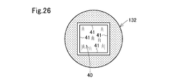
- End plates 50 and 40 are attached to flanges 16 and 23 of the core mold 9 having the wound body 32 by bolts (not shown).
- Each of the end plates 40 and 50 has a square plate shape, and ribs 41 and 51 are erected on the outer peripheral edges of the four sides. Small holes 42 and 52 are respectively provided in the ribs 41 and 51 in a direction parallel to the plate plate surface.
- the end plate 50 is provided with a circular through-hole 53 having a diameter approximately equal to the inner diameter of the cylindrical portion 12 of the core mold 9.
- the wound body 32 After attaching the end plates 40 and 50 to the core mold 9, the wound body 32 is placed on a horizontal work table so that the axial direction is horizontal. A shaped plate is pressed against the wound body 32 from above.
- the shaping plate has a rectangular frame-shaped frame and a mesh stretched on the frame. A punching plate may be used instead of the mesh.
- the shaped plate is disposed horizontally such that the long side direction is parallel to the axis of the wound body 32, and is pressed against the wound body 32 from above. After the wound body 32 is compressed to the specified thickness, the end plates 40 and 50 and the shaping plate are connected.
- the shaping plate is pressed against the remaining three directions on the outer peripheral surface of the wound body 32 and connected to the end plates 40 and 50.
- This pressed product is immersed in a binder solution containing an inorganic sol.
- a binder solution containing an inorganic sol it is preferable to immerse the pressing body in the binder liquid so that the axial center line direction of the pressing body is the vertical direction, and the end plate 50 with the through-hole 53 is downward.
- the binder liquid passes through the small holes in the front part 10 and the rear part 20 of the core mold 9 and penetrates into the inside of the compression body from the inner peripheral surface of the compression body, and permeates through the shaping plate to form the compression body. It penetrates into the inside of the compression body from the outer peripheral surface.
- the binder liquid penetrates directly into the compression body from the exposed surface not covered with the shaping plate or the end plates 40 and 50.
- the pressing body is pulled up from the binder liquid.
- the immersion time is short, the binder liquid penetrates only to the inner peripheral side and the outer peripheral side of the pressing body, and the pressing body is pulled up from the binder liquid with no or little binder liquid penetrating into the intermediate region. It is preferable.
- region 2b becomes low, while handling property improves by weight reduction, the alumina sol usage fee which is a raw material can be reduced, and manufacturing cost can be reduced.
- the pressed body After sucking and discharging the binder liquid for a predetermined time, the pressed body is transferred into a dryer (not shown), and is preferably dried at a temperature of 100 ° C. or higher. Thereafter, the compacted body is taken out from the dryer, allowed to cool, then the shaping plate is removed, and the core mold 9 is removed. At this time, the adhesive sheet wound around the wound body 32 and the release sheet wound around the core mold 9 are also removed.
- the pressed body thus dried and demolded is transferred to a firing furnace (not shown), fired, and the inorganic binder is baked onto the inorganic fibers. Thereby, a burner tile body is obtained.
- a main hole 3 for burner arrangement is formed by removing the core mold 9.
- the protruding portion (burr) is cut out from the burner tile body, and the burner tile body is shaped to a standard size, and pilot burner holes and site holes are drilled as necessary.
- a high-speed shearing device such as a band saw is used to process the shape of the connecting portion with the burner.
- pilot burner holes and site holes are provided on the burner tile, it is preferable to load the burner tile into a box-shaped guide with a set angle and position, and perform drilling with a cork borer. It is not limited to.
- the burner tile 1 manufactured in this way the excess binder liquid that has permeated into the pressing body is sucked and discharged to the inner hole side.
- the high bulk density portion 4 is formed along the inner peripheral surface of the main hole 3 of the burner tile 1. Since the high bulk density portion 4 has a high bulk density, it has excellent wind erosion resistance.
- This burner tile 1 is composed of inorganic fibers and an inorganic binder, is excellent in fire resistance, heat resistance, and thermal shock resistance, and does not require preheating at the time of temperature increase.
- region 2b is small, it is lightweight and is excellent in handling property.
- FIG. 11 is a longitudinal sectional view of the furnace wall of the furnace 80 provided with the burner and the burner tile 1.
- the burner tile 1 is arranged inside the furnace at a burner installation port 81 provided in the iron skin 85 of the furnace 80.
- a burner tip 83 of the burner 82 is inserted into the main hole 3 of the burner tile 1.
- a fireproof and heat insulating fiber molded body 84 such as alumina fiber is disposed around the burner tile 1.
- the burner tile 1 is provided with a pilot burner hole 86.
- the shape of the burner tile 1 is an example of the burner tile of the present invention, and the burner tile of the present invention may have other shapes. 12 and 13 show examples of other burner tile shapes.
- the main hole 3A has an equal-diameter cylindrical shape inside the furnace.
- the main hole 3B has a hemispherical shell shape inside the furnace.
- the main hole may have a tapered shape whose diameter increases from one end side toward the other end side.
- the burner tile is manufactured by winding the inorganic fiber laminate.
- the plate-like inorganic fiber laminate 90 is laminated to form a cube or a rectangular parallelepiped.
- the burner tile may be manufactured by forming a main hole 3 by perforating it.
- a burner tile can be manufactured by alternately laminating long and thin rectangular plate-like inorganic fiber laminates 91 to form a rectangular parallelepiped shape, and forming main holes 3 by perforating the rectangular parallelepiped shape.
- the aspect which winds an inorganic fiber laminated body from the point of the simplicity of the manufacturing process of a burner tile, and the durable improvement of the manufactured burner tile is preferable.
- the needle inorganic fiber aggregate is deformed by an external pressure when the outer shape of the burner tile 1 is formed into a quadrangular prism shape, and as a result, there is a tendency that a gap is generated between the needle inorganic fiber aggregates.
- a needle inorganic fiber assembly having a relatively high bulk density is obtained by having a structure in which a needle inorganic fiber assembly having a relatively low bulk density and a needle inorganic fiber assembly having a relatively high bulk density are laminated.
- the gap formed by deforming the body is moderately deformed by the needle inorganic fiber aggregate having a relatively low bulk density, so that the gap is filled, and as a result, a burner tile can be formed in which no gap is generated between the layers.
- a burner tile can be formed in which no gap is generated between the layers.
- the burner tile 1E has a main hole 3E penetrating in the furnace inside / outside direction.
- the tip end side of the burner is inserted into the main hole 3E from the outside of the furnace.
- the diameter of the main hole 3E is larger on the inner side of the furnace on the right side than on the outer side of the left side of FIG. 21, but is not limited thereto.
- This burner tile 1E has an inner canopy 120 and an outer canopy 130 surrounding the inner canopy 120.
- the inner jacket portion 120 surrounds the inside of the furnace in the main hole 3E.
- the outer jacket portion 130 surrounds the outer side of the furnace in the main hole 3 ⁇ / b> E and also surrounds the outer peripheral side of the inner jacket portion 120.
- the outer diameter of the inner canal portion 120 is slightly smaller than the outer diameter on the distal end side (furnace inner side). Thereby, it is prevented that the inner jacket part 120 moves to the inside of a furnace.
- the inner jacket portion 120 includes a first plate 121 having a triangular or trapezoidal cross section perpendicular to the axis of the main hole 3E, and a second plate 122 having a rectangular cross section perpendicular to the axis of the main hole 3E. Alternating layers are stacked.
- the first plate 121 having a triangular or trapezoidal cross section is arranged so that the apex side of the triangle or the short side of the trapezoid faces the inner peripheral surface of the main hole 3E.
- the second plate body 122 having a rectangular cross section is arranged so that one short side of the rectangle faces the inner peripheral surface of the main hole 3E.
- the plate bodies 121 and 122 have the longitudinal direction as the axial direction of the main hole 3E.
- a winding body composed of a laminate of the plate bodies 121 and 122 surrounding the main hole 3E is configured.
- the plate surfaces of the plate bodies 121 and 122 are substantially in the radial direction with respect to the main hole 3E.
- the outer jacket 130 is formed by rotating a mat-like inorganic fiber molded body (blanket) 131 around the rear of the main hole 3E and the outer periphery of the inner jacket 120 a plurality of times.
- the inner peripheral surface of the main hole 3E is constituted by the outer cover portion 130 outside the furnace of the burner tile 1E.
- the inner jacket portion 120 is disposed from the front end surface inside the furnace of the burner tile 1E to the middle of the furnace inside / outside direction.
- the jacket portion 130 is formed by winding an inorganic fiber molded body (blanket) around a core mold.
- the inner canopy portion 120 is disposed only on the inner side of the furnace and the outer portion of the inner peripheral surface of the main hole 3E is formed by the outer mantle portion 130, the shape accuracy of the inner peripheral surface of the main hole outside the furnace can be increased.
- the burner nozzle can be coaxially arranged with the main hole 3E with high accuracy.
- the outer shape of the burner tile 1E is a rectangular parallelepiped shape. As shown in FIG. 21, when the thickness of the burner tile 1E is T 0 and the average thickness of the inner sleeve 120 is T 1 in a cross section where the thickness is the smallest in the radial direction from the axis of the main hole 3E, T 1 /
- the percentage of T 0 is preferably 20 to 70%, particularly 30 to 60%.
- the portion along the inner peripheral surface 3f of the main hole 3E is a high bulk density portion 4 having a high bulk density, as in FIG.
- this burner tile 1E is formed by forming a burner tile-shaped molded body using the inorganic fiber blanket plates 121 and 122 and the blanket 131, and then attaching an inorganic binder, and then drying and firing. It is manufactured through the process of.
- the high bulk density portion 4 is formed along the inner peripheral surface 3f by attaching a large amount of the inorganic binder to the portion along the inner peripheral surface 3f of the main hole.
- the longitudinal sectional view of the burner tile 1E according to this embodiment and the furnace wall provided with the burner tile 1E is the same as FIG.
- the inner peripheral surface of the main hole that comes into contact with the combustion gas G is constituted by an inner sheath portion 120 in which inorganic fiber plate bodies 121 and 122 are laminated with the respective plate surfaces as radial directions.
- the interface between the inner jacket portion 120 and the outer jacket portion 130 is separated from the inner peripheral surface of the main hole 3E. Therefore, even when the burner is operated for a long period of time and the crystallization of the inorganic fibers constituting the plate bodies 121 and 122 proceeds, the soundness of the bonding surface between the inner sheath portion 120 and the outer sheath portion 130 is maintained, and the plate body The falling off of 121 and 122 is prevented.
- the burner flame may be eccentric with respect to the traveling direction and local heating may occur, but the inorganic fibers constituting the inner wall are divided in the circumferential direction, and further the compression in the shrinking direction of the inorganic fibers. Because it has been made, falling off is prevented.
- the overlapping surface of the plate bodies 121 and 122 constituting the inner sheath portion 120 extends in the radial direction, but the outer sheath portion 130 is obtained by rotating the outer periphery of the inner sheath portion 120 a plurality of times around the inorganic fiber laminate. Therefore, heat transfer from the overlapping surfaces of the plates 121 and 22 is blocked by the mantle 130, and the heat insulating property of the burner tile 1E is good. Since the high bulk density portion 4 is formed along the inner peripheral surface of the main hole 3E, wind erosion on the inner peripheral surface of the main hole 3E is prevented even when the gas G is ejected at a high flow rate.
- the burner tip 83 can be installed coaxially with the main hole 3E with high accuracy.
- the shape of the burner tile 1E is an example of the burner tile of the third invention, and the burner tile of the third invention may have other shapes.
- the main hole may have a tapered shape whose diameter increases from one end side toward the other end side.
- FIGS. 22a is a cross-sectional view in the axial direction of the core mold 109 used for forming the burner tile 1E, and is a cross-sectional view taken along the line XXIIa-XXIIa in FIG. 22b.
- 22b is a cross-sectional view taken along line XXIIb-XXIIb of FIG. 22a.
- the core mold 109 has a front part 110 and a rear part 111 assembled to the front part 110.
- the front part 110 has a cylindrical shape and is manufactured by a punching plate having a large number of small holes.
- the front part 110 includes a cylindrical part 112, a plurality of (three in this embodiment) spokes 113 provided in the centripetal direction on the front end surface of the cylindrical part 112, and a boss in which the front side in the centripetal direction of each spoke 113 is connected.
- the rear part 111 has a cylindrical shape and is manufactured by a punching plate having a large number of small holes.
- the rear part 111 is provided on the outer periphery on the rear side of the first cylindrical portion 111a having a small diameter, the second cylindrical portion 111b having a large diameter connected to the rear side of the first cylindrical portion 111a, and the second cylindrical portion 111b.
- Flange 111c a plurality of spokes 111d provided in the centripetal direction from the front side of the first cylindrical portion 111a, a boss 111e in which the front end side in the centripetal direction of each spoke 111d is continuous, and an axis of the front part 110 from the boss 111e And a long bolt 111f erected so as to pass therethrough.
- the first cylindrical portion 111a of the rear part 111 is brought into contact with the inward flange portion 117 of the front part 110, the tip of the long bolt 111f is passed through the bolt insertion hole 115, and the nut 118 is screwed to the tip of the long bolt 111f.
- the parts 110 and 111 are preferably made of metal or synthetic resin, particularly metal.
- plate bodies 121 and 122 made of inorganic fiber blankets are respectively attached to the outer periphery of the front part 110.
- the plate surfaces 121, 122 are alternately stacked in the circumferential direction so that the plate surface is in a radial direction with respect to the axis of the core mold 109, and surrounds the front part 110.
- the means for compressing the plates 121 and 122 is not particularly limited, but can be achieved by using an auxiliary device such as a tightening belt, tightening to a predetermined compression rate, and fixing with a bandage or tape (not shown). it can.
- the compression ratio is preferably 10% or more from the required physical properties such as wind erosion resistance, and is preferably 50% or less in order to prevent the fibers from being crushed by compression.
- an inorganic fiber laminate (blanket) 131 is wound around the outer periphery of the rear part 111 and the outer periphery of the wound body of the inorganic fiber plate bodies 121 and 122.
- the inorganic fiber laminated body 131 has a narrow width portion 131a at the front end side, a portion subsequent to the narrow width portion 131b, and a portion subsequent to the medium width portion 131b as a full width portion 131c.
- the inorganic fiber laminate 131 may be a laminate of two or more inorganic fiber blankets having different densities.
- the winding diameter becomes substantially equal to the diameter of the second cylindrical part 111b. Therefore, the intermediate width portion 131b is wound across the outer periphery of the wound body of the narrow width portion 131a and the outer periphery of the second cylindrical portion 111b. When all of the intermediate width portion 131b is wound, the winding diameter is substantially equal to the outer diameter of the winding body of the plate bodies 121 and 122. Therefore, the full width portion 131c is wound over the outer peripheral surface of the wound body of the middle width portion 131b and the outer peripheral surface of the winding body of the plate bodies 121 and 122, and the wound body 132 shown in FIGS. Form.
- the wound body 132 After attaching the end plates 40 and 50 to the core mold 109, the wound body 132 is placed on a horizontal work table so that the axial direction is horizontal. A shaped plate is pressed against the wound body 132 from above.
- the shaping plate has a rectangular frame-shaped frame and a mesh stretched on the frame. A punching plate may be used instead of the mesh.
- the shaped plate is arranged horizontally so that the long side direction is parallel to the axis of the wound body 132, and is pressed against the wound body 132 from above. After the wound body 132 is compressed to the specified thickness, the end plates 40 and 50 and the shaping plate are connected.
- the shaping plate is pressed against the remaining three directions of the outer peripheral surface of the wound body 132 and connected to the end plates 40 and 50.
- This pressed product is immersed in a binder solution containing an inorganic sol.
- a binder solution containing an inorganic sol it is preferable to immerse the pressing body in the binder liquid so that the axial center line direction of the pressing body is the vertical direction, and the end plate 50 with the through-hole 53 is downward.
- the binder liquid passes through the small holes in the front part 110 and the rear part 20 of the core mold 109 and penetrates into the inside of the compression body from the inner peripheral surface of the compression body, and permeates through the shaping plate. It penetrates into the inside of the compression body from the outer peripheral surface.
- the binder liquid penetrates directly into the compression body from the exposed surface not covered with the shaping plate or the end plates 40 and 50.
- the pressing body is pulled up from the binder liquid.
- the immersion time can be adjusted as appropriate according to the size and structure of the pressed body or the composition of the binder liquid, but air bubbles can be visually confirmed from the pressed body after the pressed body has penetrated the binder liquid. It is preferable to carry out to such an extent that it disappears. It should be noted that the immersion time is short, the binder liquid penetrates only to the inner peripheral side and the outer peripheral side of the pressing body, and the pressing body is pulled up from the binder liquid with no or little binder liquid penetrating into the intermediate region. May be.
- region 1b becomes low, and handling property improves by weight reduction.
- the amount of alumina sol used as a raw material can be reduced, and the manufacturing cost can be reduced.
- the pressed body After sucking and discharging the binder liquid for a predetermined time, the pressed body is transferred into a dryer (not shown), and is preferably dried at a temperature of 100 ° C. or higher. Thereafter, the compressed body is taken out from the dryer, allowed to cool, then the shaping plate is removed, and the core mold 109 is removed. At this time, the adhesive sheet wound around the wound body 132 and the release sheet wound around the core mold 109 are also removed.
- the pressed body thus dried and demolded is transferred to a firing furnace (not shown), fired, and the inorganic binder is baked onto the inorganic fibers. Thereby, a burner tile body is obtained.
- a main hole 3E for burner arrangement is formed by removing the core mold 109.
- the protruding portion (burr) is cut out from the burner tile body, the burner tile body is shaped to a standard size, and pilot burner holes and site holes are drilled as necessary to burner tile 1E.
- a high-speed shearing device such as a band saw is used to process the shape of the connecting portion with the burner.
- pilot burner holes and site holes are provided on the burner tile, it is preferable to load the burner tile into a box-shaped guide with a set angle and position, and perform drilling with a cork borer. It is not limited to.
- the burner tile 1E manufactured in this way the excess binder liquid that has permeated into the pressing body is sucked and discharged to the inner hole side.
- the high bulk density portion 4 (FIG. 4) is formed along the inner peripheral surface of the main hole 3E of the burner tile 1E. Since the high bulk density portion 4 has a high bulk density, it has excellent wind erosion resistance.
- This burner tile 1E is composed of inorganic fibers and an inorganic binder, is excellent in fire resistance, heat resistance, and thermal shock resistance, and does not require preheating at the time of temperature rise. Moreover, since the bulk density of the intermediate
- the outer jacket portion 130 that forms the outside of the furnace in the inner peripheral surface of the main hole 3E is formed according to the shape of the core mold 109, and thus has a highly round cylindrical shape.
- the burner tile 1E is equally divided into three in the radial direction with respect to the axis of the main hole 3E, and the 1/3 region closest to the main hole 3E is the inner peripheral region. 1a, the outermost 1/3 region is defined as the outer peripheral region 1c, the 1/3 region between the regions 1a and 1c is defined as the intermediate region 1b, and the thickness direction from the inner peripheral surface 3f of the inner peripheral region 1a to the thickness direction
- This burner tile 1E also preferably has a plurality of inorganic binder-carrying inorganic fiber aggregate layers having different bulk densities in the intermediate region 1b.
- the bulk density may decrease linearly from the inner peripheral surface 3f side to the outer surface, and is relatively abrupt from the inner peripheral side to the intermediate region as shown in FIG. Further, the bulk density may be decreased, and the bulk density may be gradually decreased from the intermediate region to the outer surface.
- the bulk density may increase again in the vicinity of the outer surface as shown in FIG.
- the bulk density in the vicinity of the outer surface is increased in this manner, deformation of the outer surface when the outer surface of the burner tile is touched is reduced, and handling of the burner tile is facilitated.
- a preferable range of Do is the same as that of the burner tile 1.
- This burner tile 1E is excellent in wind erosion resistance because the high bulk density portion 4 is provided along the inner peripheral surface 3f of the main hole.
- the burner tile 1E is light in weight and excellent in thermal shock resistance because the bulk density of the intermediate region 1b is small.
- Having a wound layer inorganic fiber molded body composed of a plurality of inorganic binder-carrying inorganic fiber aggregate layers having different bulk densities is preferable in terms of satisfying uniform thermal conductivity, and improves both wind erosion resistance and impact relaxation properties. It is preferable in that it can be performed.
- the needle inorganic fiber aggregate (blanket) is deformed by an external pressure when the outer shape of the burner tiles 1 and 1E is formed into a quadrangular prism shape, and as a result, there is a tendency that a gap is generated between the needle inorganic fiber aggregates.
- a needle inorganic fiber assembly having a relatively high bulk density is obtained by having a structure in which a needle inorganic fiber assembly having a relatively low bulk density and a needle inorganic fiber assembly having a relatively high bulk density are laminated.
- the gap formed by deforming the body is moderately deformed by the needle inorganic fiber aggregate having a relatively low bulk density, so that the gap is filled, and as a result, a burner tile can be formed in which no gap is generated between the layers.
- a burner tile can be formed in which no gap is generated between the layers.
- the outer shape of the burner tiles 1 and 1E is a quadrangular prism shape, but the outer shape of the burner tile may be a polygonal column shape such as a columnar shape or a hexagonal column.
- the columnar burner tile is preferably manufactured through a process of forming a substantially cylindrical compressed body using two shaped plates of a half-cylindrical shape (divided into two parts), and a quarter-cylindrical shape. It is also preferable to manufacture through a process of forming a substantially cylindrical pressing body using four (four-divided shape) shaping plates. It is preferable that the hexagonal columnar burner tile is manufactured through a process of forming a compressed body by pressing and compressing the wound body from six directions with six shaping plates.
- a hexagonal columnar or octagonal columnar burner tile may be manufactured by cutting a square columnar burner tile.
- the pressing body is immersed in the binder liquid, but the binder liquid may be impregnated on the inner peripheral surface side and the outer peripheral surface side by spraying, coating, or the like.
- the binder liquid may be impregnated into the wound body before forming the inorganic fiber mat or the pressed body.
- This burner tile 1F is composed of a cylindrical body along the inner peripheral surface of the main hole inside the furnace, and a main body in which the cylindrical body is detachably fitted.
- a slip-out preventing means for preventing the slip-out is provided.
- This burner tile 1F has an inner mantle portion 150 (tubular body) and an outer mantle portion 160 (main body) into which the inner mantle portion 150 is inserted, like the burner tile 1E.
- the inner sleeve 150 (cylindrical body) includes a first plate 121 having a triangular or trapezoidal cross section perpendicular to the axis of the main hole 3E, and a second plate having a rectangular cross section perpendicular to the axis of the main hole. It is manufactured by alternately laminating the bodies 122 and retaining the shape in a cylindrical shape, impregnating with a binder liquid, drying and firing. A projecting portion 152 from the outer peripheral surface on the rear end side of the inner canopy portion 150 projects in the radial direction. This convex portion is integrated with at least one of the plates 121 and 122. Note that a plurality of convex portions, grooves extending in the direction parallel to the axial center line, and key grooves may be provided.
- the first plate 121 having a triangular or trapezoidal cross section is arranged so that the apex side of the triangle or the short side of the trapezoid faces the inner peripheral surface of the main hole.
- the second plate body 122 having a rectangular cross section is arranged so that one short side of the rectangle faces the inner peripheral surface of the main hole.
- the plate bodies 121 and 122 each have the longitudinal direction as the axial direction of the main hole.
- the outer mantle portion 160 (main body) has an inner hole 161 into which the inner mantle portion 150 is inserted.
- a groove 162 extending in a direction parallel to the axis of the inner hole 161 is provided on the inner peripheral surface of the inner hole 161.
- the innermost part of the groove 162 is a key groove 162 a extending in the circumferential direction of the inner hole 161.
- an inorganic fiber molded body (blanket) is wound around a core mold similar to that shown in FIG. 22a, and end plates 40 and 50 are attached to the core mold as shown in FIG. And it is set as the crimping
- the pressed body is impregnated with a binder solution, dried, demolded, and fired.
- a groove 162 and a key groove 162 a are formed by cutting the inner peripheral surface of the outer cover portion 160. Further, the groove 162 and the key groove 162a may be formed at the time of molding the mantle part by providing a convex part of the same size on the mold.
- the convex portion 152 is engaged with the groove 162, the inner canopy portion 150 is engaged with the inner hole 161 of the outer sheath portion 160, and then the inner canopy portion 150 is rotated in the circumferential direction so that the convex portion 152 is engaged with the key groove 162a.
- the groove 162 is filled with the filler of the inorganic fiber laminate.
- the burner tile 1F is configured.
- the inorganic fiber laminate sheet 151 is wound around the outer periphery of the inner canopy 150, and the outer periphery of the inner canopy 150 and the inner holes 161 of the outer canopy 160 are formed. It is preferable to interpose the inorganic fiber laminate sheet 151 in the gap.
- the inner canopy portion 150 is easily held in the inner hole 161 of the outer mantle portion 160 by the restoring force (repulsive force) of the inorganic fiber laminate sheet 151.
- the restoring force repulsive force
- seat 151 you may restrain with the rope for binding (illustration omitted) which lose
- the amount of binder attached is increased on the inner peripheral surface side of the main hole, and a high bulk density is formed along the inner peripheral surface of the main hole.
- the cylindrical body 170 constitutes the inner peripheral surface inside the furnace of the main hole 3 of the burner tile 1G.
- the main body 180 has an inner hole 181 into which the cylindrical body 170 is inserted.
- a groove 182 extending in the axial direction of the inner hole 181 is provided on the inner peripheral surface of the inner hole 181.
- Key grooves 182a and 182b extending in the circumferential direction of the inner hole 181 are provided in the middle and the innermost part of the groove 182 in the longitudinal direction.
- two convex portions 171 and 172 project from the axial center line direction of the cylindrical body 170 with a gap therebetween.
- the cylindrical body 170 is rotated in the circumferential direction so that the convex portions 171 and 172 are engaged with the key grooves 182a and 182b. Then, the burner tile 1G is formed by filling the groove 182 with the filler of the inorganic fiber laminate.
- the cylindrical body 170 can be taken out from the main body 180 and repaired or exchanged.
- the cylindrical body 170 has a tapered shape having a larger diameter toward the inside of the furnace, and is easily moved to the inside of the furnace. For this reason, the cylindrical body 170 is prevented from moving in the furnace direction by providing and engaging two convex portions 171 and 172 and key grooves 182a and 182b, respectively.
- the number of convex portions and key grooves may be one, or may be three or more.
- a plurality of grooves extending in the direction parallel to the axial line may be provided.
- the groove 182 and the key grooves 182a and 182b can be formed by cutting. Further, the groove 182 and the key grooves 182a and 182b may be formed at the time of molding the mantle part by providing a convex part of the same size on the mold.
- the cylindrical body 170 with the convex portions 171 and 172 In order to manufacture the cylindrical body 170 with the convex portions 171 and 172, as shown in FIG. 30, a cylindrical body having a circumferential ridge portion 173 on the outer peripheral surface is manufactured, and the circumferential ridge portion 173 is cut.
- the convex portions 171 and 172 may be formed by processing.
- the cylindrical body 170 with convex portions can also be manufactured by providing a concave hole 174 on the outer peripheral surface of the cylindrical body 170 and fitting a piece 175 made of inorganic fiber into the concave hole 174. .
- the wide portion 176a of the band-like sheet 176 made of inorganic fibers having the wide portion 176a and the narrow portion 176b is attached to the outer surface of the tubular body 170 with an inorganic adhesive, and the narrow portion 176b is zigzag
- the cylindrical body 170 with a convex portion can also be produced by folding and bonding the wide portion 176a with an inorganic adhesive.
- the burner tile is divided into three equal parts in the radial direction with respect to the axial center of the main hole, and the 1/3 region closest to the main hole side
- the outer peripheral region 1c is the outermost region 1c
- the third region between the regions 1a and 1c is the intermediate region 1b
- the inner peripheral region 1a has an inner peripheral surface 3f.
- the inorganic fiber plates 121 and 122 and the laminates 30, 31, and 131 are preferably manufactured based on JP2011-208344, but are not limited thereto.
- the inorganic fiber laminate is preferably composed of a needle inorganic fiber aggregate such as a needle blanket in which an inorganic fiber having an alumina weight fraction of 65% by weight or more is subjected to a needling treatment, and particularly two or more kinds of needle inorganic fibers. It is preferable that the aggregate is laminated.
- the inorganic fiber constituting the needle inorganic fiber aggregate is preferably an alumina fiber having an alumina weight fraction of 65% by weight or more, specifically, alumina / silica, zirconia containing these, spinel, titania alone, or the like
- an alumina / silica-based fiber, particularly a polycrystalline alumina / silica-based fiber is particularly preferable in terms of heat resistance, fiber strength (toughness), and safety.
- composition ratio (weight ratio) of alumina / silica fiber is preferably in the range of 65 to 98/35 to 2 called mullite composition or high alumina composition, more preferably 70 to 95/30 to 5, particularly preferably in the range of 70 to 74/30 to 26.
- the inorganic fiber constituting the needle blanket is 80% by weight or more, preferably 90% by weight or more, and particularly preferably the total amount thereof is a polycrystalline alumina / silica fiber having the above mullite composition.
- the inorganic fiber laminate constituting the plate bodies 121 and 122 and the laminates 30, 31 and 131 is preferably composed of at least one of needle inorganic fiber aggregates A, B, C, and D described later.
- the inorganic fiber laminates 31 and 131 are preferably composed of at least one of the needle inorganic fiber assemblies B and C.
- a needle blanket made of inorganic fibers having an alumina weight of less than 65% may be provided.
- the needle mark density of the needle inorganic fiber assembly A is 1.0 stroke / cm 2 or more, preferably 1.5 stroke / cm 2 or more, while it is less than 5.0 stroke / cm 2 , preferably Is 3.0 strokes / cm 2 or less.
- the shape deformation performance of the wound body 132 is good, which is preferable.
- the bulk density of the needle inorganic fiber aggregate A is preferably 0.02 to 0.10 g / cm 3 , more preferably 0.04 to 0.08 g / cm 3 . When the bulk density is within this range, the handling property in the step of shaping the wound body 132 is good, which is preferable.
- the surface density of the needle inorganic fiber aggregate A is preferably 800 to 1400 g / m 2 , particularly 900 to 1300 g / m 2 , and particularly preferably 1000 to 1200 g / m 2 .
- the handling property in the step of shaping the wound body 132 is good, which is preferable.
- the thickness of the needle inorganic fiber assembly A is not particularly limited, but is usually preferably about 35 to 60 mm.
- the needle mark density of the needle inorganic fiber assembly B is more than 5.0 shots / cm 2 , preferably 6.0 shots / cm 2 or more, while it is 10.0 shots / cm 2 or less, preferably 9.0 strokes / cm 2 or less.
- the shape retention performance of the burner tile and the shape deformation performance of the burner tile are good, which is preferable.
- the bulk density of the needle inorganic fiber aggregate B is preferably 0.06 to 0.16 g / cm 3 , and more preferably 0.08 to 0.14 g / cm 3 .
- the shape retention performance of the burner tile is good, which is preferable.
- the surface density of the needle inorganic fiber aggregate B is preferably 2200 to 3600 g / m 2 , particularly 2300 to 3500 g / m 2 , particularly 2400 to 3200 g / m 2 .
- the shape retention performance of the burner tile is good, which is preferable.
- the thickness of the needle inorganic fiber aggregate B is not particularly limited, but is usually preferably about 20 to 30 mm.
- the needle mark density of the needle inorganic fiber assembly C is more than 10.0 shots / cm 2 , preferably 12.0 shots / cm 2 or more, while it is 17.0 shots / cm 2 or less, preferably 16.0 strikes / cm 2 or less.
- the needle mark density is in this range, the wind erosion resistance of the burner tile becomes good, which is preferable.
- the bulk density of the needle inorganic fiber assembly C is preferably 0.120 ⁇ 0.175g / cm 3, more preferably 0.135 ⁇ 0.19g / cm 3. When the bulk density is within this range, the wind erosion resistance of the burner tile becomes good, which is preferable.
- the surface density of the needle inorganic fiber assembly C is, 1000 ⁇ 2000g / m 2, in particular 1200 ⁇ 1800g / m 2, it is preferred especially is 1400 ⁇ 1600g / m 2.
- the areal density is within this range, the wind erosion resistance of the burner tile becomes good, which is preferable.
- the thickness of the needle inorganic fiber aggregate C is not particularly limited, but is usually preferably about 8.0 to 12.0 mm.
- needle inorganic fiber aggregate D The needle mark density and bulk density of the needle inorganic fiber aggregate D are the same as those of the needle inorganic fiber aggregate D.
- the thickness of the needle inorganic fiber aggregate D is not particularly limited, but is preferably about 8 to 15 mm.
- a laminated mat having a three-layer structure of needle inorganic fiber aggregate C / needle inorganic fiber aggregate A / needle inorganic fiber aggregate B is wound around the core mold 9 or the needle inorganic fiber aggregate A , B, and C are preferably individually wound around the core mold 9 to form a wound body of the first inorganic fiber laminate 30.
- a laminated body having a two-layer structure of needle inorganic fiber aggregate A / needle inorganic fiber aggregate B may be wound, or the needle inorganic fiber aggregates A and B are individually wound. May be.
- one needle inorganic fiber aggregate is individually wound, it can be easily wound around a core shape having a complicated shape.
- the plate bodies 121 and 122 are preferably composed of needle inorganic fiber assemblies B or D.
- a laminated mat having a two-layer structure of the needle inorganic fiber assembly A / needle inorganic fiber assembly B is used as the winding body of the plate bodies 121 and 122.
- the wound body of the inorganic fiber laminated body 131 is formed by winding or individually winding the needle inorganic fiber aggregates A and B around the plate bodies 121 and 122.
- the inorganic binder constituting the inorganic binder liquid is not particularly limited as long as it forms an oxide after firing, such as an inorganic sol and a metal salt, or a mixture thereof.
- Examples of the inorganic sol include alumina sol, zirconia sol, titania sol, magnesia sol, and calcia sol.
- Examples of the metal salt include organic acid salts such as formic acid, acetic acid, citric acid, oxalic acid, benzoic acid and malic acid, and mineral salts such as nitric acid.
- alumina sol is preferable in that the coefficient of thermal expansion is close to that of the inorganic fiber aggregate.
- a plurality of inorganic sols may be used as the inorganic binder.
- the concentration of the inorganic binder liquid is preferably 6 to 14% by weight, particularly 8 to 11% by weight as the solid content.
- the viscosity of the binder liquid is preferably adjusted to 5 to 200 cp.
- the adhesion rate of the inorganic binder in the outermost layer and the innermost layer in the wound bodies 32, 132 is 1.0 times or more and 2.0 times, respectively, compared with the adhesion rate at the midpoint between the outermost layer and the innermost layer in the thickness direction. From the standpoint of maintaining the outer shape of the burner tile, it is preferably 1.5 times or more and 10.0 times or less. This ratio is particularly preferably 1.1 times or more and 1.9 times or less and 3.0 times or more and 8.0 times or less, respectively.
- the adhesion rate of an inorganic binder means the ratio which represented the weight of the inorganic binder solid content with respect to the weight of an inorganic fiber with the percentage as a following formula.
- (Attachment rate) (inorganic binder solid content weight) / (inorganic fiber aggregate weight) ⁇ 100
- Examples of the method for measuring the adhesion rate of the inorganic binder to the inorganic fibers include a firing method, which can be specifically measured by a method described in a known document (International Publication No. 2013/035645).
- additives such as a dispersant may be added to the binder liquid as long as the effects of the present invention are not impaired.
- the drying conditions are not particularly limited. Specifically, the outermost layer is contacted with hot air of 60 ° C. to 200 ° C., or left in an atmosphere of 100 ° C. to 200 ° C. for about 2 to 5 hours. The method of letting it be mentioned. This is preferable because the amount of the outermost inorganic sol can be increased.
- the suction dehydration step and the drying step may be performed at the same time, so that the work efficiency is improved.
- baking is preferably performed at 600 ° C. to 1200 ° C. in an oxygen-containing atmosphere such as air in which the organic component is completely lost and corundumization of an inorganic binder such as alumina sol is performed.
- the burr 1a is cut off by an NT cutter or the like, or the burner tile outer surface is shaped into a standard shape.
- a burner tile is installed at the tip of a pipe that can transfer compressed air so that the flame opening faces upward, and the front side (furnace inside) opening of the main hole is an inorganic fiber molded body having a density of 0.17.0 g / cm 3. It was closed at. Thereafter, compressed air of 0.1 MPa is blown from the lower part into the burner tile, the detergent foam is applied to the outer surface of the burner tile, the presence or absence of bubble expansion is visually observed, and the presence or absence of splitting is confirmed.
- Burner tile 1 was manufactured using core mold 9 having the shape shown in FIG.
- the dimensions of each part of the core mold 9 are as follows.
- Axial length of front part 10 192 mm
- Maximum inner diameter of front part 10 122mm
- Minimum inner diameter of front part 10 85mm
- Axial length of rear part 20 106mm
- Maximum inner diameter of rear part 20 85mm
- Minimum inner diameter of rear part 20 61mm
- Alumina fiber needle blanket (Mitsubishi Resin Corporation MAFTEC (registered trademark), hereinafter referred to as needle blanket A)) having a thickness of 50 mm and a needle mark density of 3.0 strokes / cm 2 is 320 mm wide and 2000 mm long.
- An alumina fiber needle blanket (Mitsubishi Resin Corporation MAFTEC (registered trademark) 8P25T or less needle blanket B) having a needle mark density of 6.0 mm / cm 2 was cut into a width of 320 mm and a length of 2500 mm. Further, using an inner die, an alumina fiber needle blanket (Mitsubishi Resin Co., Ltd.
- MAFTEC registered trademark
- needle blanket C MAFTEC (registered trademark), hereinafter referred to as needle blanket C) having a thickness of 10 mm and a needle mark density of 12.0 strokes / cm 2 is center angle 55 degrees.
- a semicircle with a central angle of 55 degrees and a radius of 363 mm was cut out into a sector shape.
- a sector shape was cut out from a semicircle with a center angle of 65 degrees and a radius of 565 mm, and a semicircle with a center angle of 65 degrees and a radius of 408 mm was cut out.
- the core mold 9 was wound once with a glass cloth having a thickness of 0.5 mm (manufactured by Chuko Kasei Co., Ltd .: Chuko Flow (registered trademark) G type fabric) as a release sheet. Thereafter, the first inorganic fiber laminate 30 was formed by winding the fan shape of the needle blanket C around the corresponding core type portion (front part 10) at the portion expected to be exposed to the severest wind speed. Thereafter, the needle blanket A was superposed on the needle blanket B to form a second inorganic fiber laminate 31, which was wound as shown in FIG. 8 to produce a wound body 32 having a diameter of 330 mm and a length of 320 mm.
- the shaped plate After attaching the end plates 40 and 50 to both end faces of the wound body 32 as shown in FIG. 9, the shaped plate is pressed against the wound body 32 and connected to the end plates 40 and 50, and a square with a side of 254 mm. A columnar pressing body was used.
- the pressed body was dipped in alumina sol (Nissan Chemical Co., Ltd., alumina sol 200) having a solid content concentration of 8% by weight for 30 minutes and then lifted and dehydrated at a negative pressure of -17.5 to -22.5 kPa for 45 minutes. Thereafter, the pressed body was surrounded by a box, and while the suction was continued, 100-140 ° C. warm air was introduced into the box for 4 hours to dry it. After drying, the shaped plate was removed and the core mold 9 was removed. Subsequently, it baked at 1000 degreeC in the air atmosphere for 3 hours.
- alumina sol Nisan Chemical Co., Ltd., alumina sol 200
- the burrs at the four corners of the burner tile body after firing were cut off with a cutter, and then the outer shape was shaped with a band saw to 254 ⁇ 254 ⁇ 298 mm.
- pilot burner holes and site holes were drilled with a cork borer using a front plate for installing burner tiles, and the burner tiles shown in Table 1 were manufactured.
- Example 4 (cylindrical burner tile)
- the shaft center is molded to ⁇ 100 mm, then the needle blanket B is wound to ⁇ 300 mm, and the alumina sol is impregnated only by a thickness of 50 mm on the outer peripheral portion (dropwise method) and then dried. did.
- burner tiles shown in Table 1 were produced in the same manner as in Example 3.
- Burner tiles shown in Table 1 were produced in the same manner as in Example 1 except that the inorganic sol (alumina sol) was not impregnated in Example 1.
- Axial length of front part 10 276 mm
- Maximum inner diameter of front part 10 140mm
- Minimum inner diameter of front part 10 140mm
- Axial length of rear part 20 237mm
- Maximum inner diameter of rear part 20 118mm Minimum inner diameter of rear part 20: 71mm
- An alumina fiber needle blanket (Mitsubishi Resin Co., Ltd. MAFTEC (registered trademark), hereinafter referred to as needle blanket A)) having a thickness of 50 mm and a needle mark density of 3.0 strokes / cm 2 is 320 mm wide, 2500 mm long, and thick.
- An alumina fiber needle blanket (Mitsubishi Resin Corporation MAFTEC (registered trademark) 8P25T or less needle blanket B) having a needle mark density of 6.0 mm / cm 2 was cut into a width of 533 mm and a length of 3200 mm.
- a glass cloth manufactured by Chuko Kasei Co., Ltd .: Chuko Flow (registered trademark) G type fabric
- a strip blanket B and a triangular pyramid cut out with a thickness of 12.5 mm and a needle mark density of 6.0 strokes / cm 2 .
- a pair of modules each having a pair of alumina fiber needle blankets (Mitsubishi Resin Co., Ltd. MAFTEC (registered trademark) 8P12.5T or less needle blanket D) fixed thereto was arranged radially.
- the shaped plate After attaching the end plates 40 and 50 to both end faces of the wound body 132 as shown in FIG. 25, the shaped plate is pressed against the wound body 132 and connected to the end plates 40 and 50, and a square having a side of 323 mm. A columnar pressing body was used.
- the outer shape was shaped to 323 mm ⁇ 323 mm ⁇ 513 mm with a band saw.
- pilot burner holes and site holes were drilled with a cork borer using a front plate for installing burner tiles, and the burner tiles shown in Table 2 were manufactured.
- the obtained burner tile was subjected to physical properties tests (falling ball impact test, thermal shock resistance test), burner combustion test 1 and burner combustion test 2 (presence / absence of internal wall peeling and splitting / not splitting after each test). The results are shown in Table 2.
- the physical property test and burner combustion test 2 were performed under the following conditions.
- Thermal shock resistance test A sample cut out to a predetermined size from a created burner tile along a plane passing through the axis of the core is left in an electric furnace heated to 1500 ° C. for 15 minutes. Then, it takes out from an electric furnace and leaves still for 15 minutes in the air. After repeating this operation 10 times, the appearance such as peeling and cracking was visually observed. A state in which cracks having a depth or width of 10 mm or more and peeling were observed was indicated by ⁇ , and a state in which cracks were not observed was indicated by ⁇ .
- Burner combustion test 2 Using a burner with the following specifications, burning and extinguishing for 5 minutes were repeated 10 times. Subsequently, it was burned in a test furnace at a furnace temperature of 1350 ° C. for 720 hours. Burner specifications: Model: Square type (323mm square x 513mm) Capacity: 850000 kcal / h Fuel: 13A city gas Air temperature: 400 ° C Combustion air ratio: 1.0 to 1.1
- the evaluation (inner wall observation) after the burner combustion tests 1 and 2 was performed as follows.
- the inner peripheral surface of the main hole is visually observed and the presence or absence of peeling is observed.
- the inner wall state was judged as good, and otherwise it was judged as bad.
- Example 3 A conventionally known silica-alumina castable was used and cast into a mold to form an inner cylinder. Then, the blanket A shown in Table 2 was manufactured by winding blanket A around the inner cylinder, and then surrounding the upper, lower, left, and right and front surfaces with a vacuum foam molding. About the burner tile obtained above, the physical property test and the burner combustion test were evaluated in the same manner as in Example 7. Table 2 shows the results.
- Burner tiles were manufactured using the core mold 109.
- the dimensions of each part of the core mold 109 are as follows.
- Axial length of front part 10 276 mm
- Maximum inner diameter of front part 10 140mm
- Minimum inner diameter of front part 10 140mm
- Axial length of rear part 20 237mm
- Maximum inner diameter of rear part 20 118mm Minimum inner diameter of rear part 20: 71mm
- a glass cloth manufactured by Chuko Kasei Co., Ltd .: Chuko Flow (registered trademark) G type fabric
- alumina fiber needle blanket Mitsubishi Resin Co., Ltd. MAFTEC (registered) with a strip-like thickness of 25 mm and a needle mark density of 6.0 strokes / cm 2.
- Trademarks 8P25T or less Needle blankets B were arranged in 34 pairs radially.
- the radially arranged modules were compressed using an auxiliary tool such as a fastening rope to a compression rate of 25% to form an inner canopy.
- 8 needle blankets B were cut out to a length of 161.5 mm and a width of 513 mm.
- the eight needle blankets were compressed and fixed to a thickness of 161.5 mm to produce a block.
- Four pairs of the blocks were produced, and each block was arranged so that the stacking direction of adjacent blocks was vertical, thereby obtaining a square columnar block having a side of 323 mm.
- the center of the columnar block is processed so that the inner cannula is accommodated, and after processing, the four pairs of blocks forming the columnar block from the outside of the inner cannula are fixed from the outside, thereby A square columnar block with a side of 323 mm was obtained.
- Pilot burner holes and site holes were drilled with a cork borer using a front plate for burner tile installation, and burner tiles shown in Table 2 were produced.
- the obtained burner tile was subjected to physical properties tests (falling ball impact test, thermal shock resistance test), burner combustion test 1 and burner combustion test 2 (presence / absence of internal wall peeling and splitting / not splitting after each test). The results are shown in Table 2.
- Comparative Example 6 In Comparative Example 4, the burner shown in Table 2 was carried out in the same manner as in Comparative Example 4 except that a step of impregnating alumina sol only by about 5 mm on the surface of the formed inner cylinder for combustion by brush application method was added. Tiles were manufactured. The obtained burner tile was subjected to physical properties tests (falling ball impact test, thermal shock resistance test), burner combustion test 1 and burner combustion test 2 (presence / absence of internal wall peeling and splitting / not splitting after each test). The results are shown in Table 2.
- all the burner tiles according to the examples are excellent in wind erosion resistance and thermal shock resistance.
- it has an inner mantle that surrounds the main hole, and an outer mantle that surrounds the outer periphery of the inner mantle, in which the inorganic fiber plate body has a plate surface substantially radial to the main hole.
- the burner tile according to Example 7, in which the inorganic fiber blanket is rotated around the outer periphery of the inner sheath part a plurality of times, is wind resistant and heat resistant. It can be seen that it has excellent impact properties, low heat shrinkage, and product appearance moldability.
Landscapes
- Engineering & Computer Science (AREA)
- Chemical & Material Sciences (AREA)
- Ceramic Engineering (AREA)
- Mechanical Engineering (AREA)
- General Engineering & Computer Science (AREA)
- Manufacturing & Machinery (AREA)
- Materials Engineering (AREA)
- Structural Engineering (AREA)
- Organic Chemistry (AREA)
- Combustion & Propulsion (AREA)
- Chemical Kinetics & Catalysis (AREA)
- Furnace Housings, Linings, Walls, And Ceilings (AREA)
- Gas Burners (AREA)
Abstract
Description
第2発明のバーナタイルは、無機繊維成形体よりなり、炉内外方向に貫通する、バーナ用の主孔を有するバーナタイルにおいて、該主孔の内周面に沿う部分が、該内周面と本体部外面との中間の中間部よりも嵩密度が大きい高嵩密度部となっていることを特徴とする。
無機繊維の板体121,122及び積層体30, 31,131は、特開2011-208344に基づいて製造されたものが好ましいが、これに限定されない。無機繊維積層体は、アルミナ重量分率が65重量%以上である無機繊維についてニードリング処理が施されたニードルブランケットなどのニードル無機繊維集合体よりなることが好ましく、特に2種以上のニードル無機繊維集合体を積層したものであることが好ましい。
ニードル無機繊維集合体Aのニードル痕密度は、1.0打/cm2以上であり、好ましくは1.5打/cm2以上であり、一方、5.0打/cm2未満であり、好ましくは3.0打/cm2以下である。ニードル無機繊維集合体Aのニードル痕密度がこの範囲にあることにより、巻回体132の形状変形性能が良好であり、好ましい。
ニードル無機繊維集合体Bのニードル痕密度は、5.0打/cm2より多く、好ましくは6.0打/cm2以上であり、一方、10.0打/cm2以下であり、好ましくは9.0打/cm2以下である。ニードル痕密度がこの範囲にあることにより、バーナタイルの形状保持性能およびバーナタイルの形状変形性能が良好であり、好ましい。
ニードル無機繊維集合体Cのニードル痕密度は、10.0打/cm2より多く、好ましくは12.0打/cm2以上であり、一方、17.0打/cm2以下であり、好ましくは16.0打/cm2以下である。ニードル痕密度がこの範囲にあることにより、バーナタイルの耐風食性が良好となり、好ましい。
ニードル無機繊維集合体Dのニードル痕密度および嵩密度は、ニードル無機繊維集合体Dと同様である。
無機バインダー液を構成する無機バインダーとしては、特段の制限はなく、無機質ゾルおよび金属塩、またはその混合物など焼成後に酸化物を形成するものであればよい。以下、具体例を挙げて記述するが、本発明はこれに限定されるものではない。
(添着率)=(無機バインダー固形分重量)/(無機繊維集合体重量)×100
無機繊維に対する無機バインダーの添着率の測定方法としては焼成法が挙げられ、具体的には公知文献(国際公開第2013/035645号)に記載の方法により測定することができる。
離型シートとしては、特段の制限はないが、フッ素樹脂等よりなる合成樹脂シート、ガラスクロスなどが挙げられる。
乾燥条件としては、特段の制限はないが、具体的には、最外層を60℃~200℃の熱風を接触させる方法、又は100℃~200℃の雰囲気下で、2~5時間程度静置させる方法が挙げられる。このようにすると、最外側の無機質ゾルの添着量を増加させることができ、好ましい。吸引脱水工程と乾燥工程とを同時に行ってもよく、このようにすれば作業効率が向上する。
押縮体を焼成することにより、無機質ゾルに含まれる揮発性の分散剤の除去や、水などにより濡れた際の無機質ゾルの再溶解、再溶解に伴う無機繊維成形体構造の崩れを防ぐ事が出来る。本発明においては、有機分が完全に消失し、アルミナゾル等の無機バインダーのコランダム化が為される空気などの酸素含有雰囲気中にて600℃~1200℃で焼成することが好ましい。
必要に応じて、本発明に係るバーナタイルに対して後加工を行なってもよい。例えば、バリ1aをNTカッターなどにより切落としたり、バーナタイル外面を整形して規格形状とする。
主孔内壁の最表面から火炎方向と垂直方向に5mmの厚み位置かつ火炎方向に平行の開口部最前部10mmの円周を4分割して、測定サンプルを切り出し、各サンプルの重量を測定する。その後、タフダイン(クボタシーアイ株式会社)塗布により表面を疎水性とし、メスシリンダ内の水中に投入し、水液面位置の上昇から体積を測定する。上記重量をこの体積で除算することにより高嵩密度部の嵩密度を算出した。
測定手順は次の通りである。
1) バーナタイルから所定サイズ(幅20mm×長さ50mm×厚さ5mm)のサンプルを切出す。
2) サンプル表面にタフダイン(クボタシーアイ株式会社)を塗布する。(表面に孔が無い様に、表面が平滑になるまで、場合によっては複数回塗布する。)
3) サンプルを十分に乾燥させる。
4) 乾燥後のサンプルの重量を測る。
5) 水を入れたメスシリンダに上記サンプルを投入し、体積増加を目盛りから読み取る。
6) 測定重量[g]を測定体積[mL]で割ることで嵩密度[g/mL]を求める。
下記仕様のバーナを用い、5分間の燃焼、消火を10回繰り返した。次いで、試験炉内で炉内温度1400℃で32時間燃焼させた。
1.四角型(254mm四角×298mm)2.円筒型(φ300mm×218mm)
容量:1.500000kcal/h、2.600000kcal/h
燃料:13A都市ガス
空気温度:1.400℃ 2.400℃
燃焼空気比:1.0~1.1
燃焼試験前後のバーナタイルについて、主孔の炉内側の開口径を内パスにより測定し、半径の変化の有無を確認する。
燃焼試験前後のバーナタイルについて、主孔内周面を目視にて観察し、剥離の有無を観察する。
圧縮空気を移送できる配管の先端にバーナタイルを火炎開口部が上向きとなる様に設置し、主孔のフロント側(炉内側)開口部を密度0.17.0g/cm3の無機繊維成形体にて塞いだ。その後、0.1MPaの圧縮空気をバーナタイル内に下部から送風し、バーナタイル外表面に洗剤泡を塗布し、気泡膨張の有無を目視にて観察し、割裂の有無を確認する。
焼成工程前後のバーナタイルにおいて、主孔のフロント側(炉内側)開口部を正面に位置させた際の目地開きの有無を目視にて観察する。
図6に示す形状のコア型9を用いてバーナタイル1を製造した。コア型9の各部分の寸法は次の通りである。
フロントパーツ10の軸方向長さ:192mm
フロントパーツ10の最大内径:122mm
フロントパーツ10の最小内径:85mm
リアパーツ20の軸方向長さ:106mm
リアパーツ20の最大内径:85mm
リアパーツ20の最小内径:61mm
厚さ50mm、ニードル痕密度 3.0打/cm2であるアルミナ繊維ニードルブランケット(三菱樹脂株式会社 MAFTEC(登録商標)。以下ニードルブランケットA))を320mm幅、2000mm長さに、また、厚さ25mm、ニードル痕密度 6.0打/cm2であるアルミナ繊維ニードルブランケット(三菱樹脂株式会社 MAFTEC(登録商標) 8P25T 以下ニードルブランケットB)を320mm幅2500mm長さに切出した。また、内抜き型を用いて、厚さ10mm、ニードル痕密度 12.0打/cm2であるアルミナ繊維ニードルブランケット(三菱樹脂株式会社 MAFTEC(登録商標)。以下ニードルブランケットC)を中心角度55度、半径520mmの半円から、中心角55度、半径363mmの半円をくり抜いた扇形に切出した。同様の操作で中心角度65度、半径565mmの半円から、中心角65度、半径408mmの半円をくり抜いた扇形を切出した。
実施例1において、厚み10.0mmのニードルブランケットCの代わりに厚みを12.5mmとしたニードルブランケットCを用いたこと以外は実施例1と同様にして、表1に示すバーナタイルを製造した。
前記ニードルブランケットAを190mm幅600mm長さに、前記ニードルブランケットBを240mm幅2500mm長さに切り出し、切出した。また、内抜き型を用いてニードルブランケットCを中心角度250度、半径112mmの半円から、中心角250度、半径51mmの半円をくり抜いた扇形を切出した。同様の操作でニードルブランケットCから中心角度65度、半径461mmの半円から、中心角65度、半径331mmの半円をくり抜いた扇形を切出した。切出したニードルブランケットを実施例1と同様の順番で巻付けた。また、賦形板として半円形状のもの2枚を用いた。それ以外は実施例1と同様にして表1に示すバーナタイルを製造した。
実施例3と同様の方法で、軸心からφ100mmまで成形し、その後ニードルブランケットBをφ300mmまで巻付け、外周部の厚さ50mm分にのみアルミナゾルを塗布(ドロップワイズ法)で含浸した後、乾燥した。それ以外は実施例3と同様にして表1に示すバーナタイルを製造した。
実施例1においてニードルブランケットAを使用しなかったこと以外は実施例1と同様にして表1に示すバーナタイルを製造した。
実施例1においてニードルブランケットBの代わりに、溶融法で製造されたセラミックファイバーブランケット(アルミナ/シリカ重量比=48/52)を用いたこと以外は実施例1と同様にして表1に示すバーナタイルを製造した。
実施例1において無機質ゾル(アルミナゾル)を含浸しなかったこと以外は実施例1と同様にして表1に示すバーナタイルを製造した。
従来公知のシリカ-アルミナ系キャスタブルを使用し、型枠へ流し込み成形をして、表1に示すバーナタイルを製造した。

なかでも、特定の3種のブランケットを用いた実施例1~4に係るバーナタイルは、耐風食性、耐熱衝撃性、低熱収縮率、製品外観成型性に優れるものである。まず、セルフニードリングにより強固な構造となっているニードルブランケットCを最内壁に設置することで耐風食性が向上する。また、半バルク体であるニードルブランケットAを層間に挟みこむことで、繊維集合体の反発力が小さくなり、即ち、成型性が向上する。さらに、繊維中ムライト結晶の結晶化を進行させたニードルブランケットAおよびBを成型体マトリックスとすることで、加熱した際に、熱収縮を起こしにくい構成となっている。
図24に示す形状のコア型109を用いてバーナタイル1Eを製造した。コア型109の各部分の寸法は次の通りである。
フロントパーツ10の最大内径:140mm
フロントパーツ10の最小内径:140mm
リアパーツ20の軸方向長さ:237mm
リアパーツ20の最大内径:118mm
リアパーツ20の最小内径:71mm
厚さ50mm、ニードル痕密度 3.0打/cm2であるアルミナ繊維ニードルブランケット(三菱樹脂株式会社 MAFTEC(登録商標)。以下ニードルブランケットA))を320mm幅、2500mm長さに、また、厚さ25mm、ニードル痕密度 6.0打/cm2であるアルミナ繊維ニードルブランケット(三菱樹脂株式会社 MAFTEC(登録商標) 8P25T 以下ニードルブランケットB)を533mm幅3200mm長さに切出した。
その後、ニードルブランケットAをニードルブランケットBの上に重ね合せて第2の無機繊維積層体131を形成し、図24のように、上記で得られた内套部の外側に巻付け、直径460mm、長さ533mmの巻回体132を製作した。
重量550gの鋼球を1mの高さから、製品側面中央部に垂直に落下させ、外観(破壊)状態を観察した。
作成したバーナタイルから、炉心の軸線を通る平面に沿って所定の大きさに切出したサンプルを、1500℃に加熱された電気炉内に15分間静置する。その後、電気炉より取出し、空気中で15分間静置する。この操作を10回繰り返した後、目視にて、剥離や亀裂など外観状態を観察した。10mm以上の深さまたは幅の亀裂、及び、剥離が見られた状態を○、見られない状態を×とした。
下記仕様のバーナを用い、5分間の燃焼、消火を10回繰り返した。次いで、試験炉内で、炉内温度1350℃、720時間燃焼させた。
バーナ仕様:
型式:四角型(323mm四角×513mm )
容量:850000kcal/h
燃料:13A都市ガス
空気温度:400℃
燃焼空気比:1.0~1.1
燃焼試験前後のバーナタイルについて、主孔内周面を目視にて観察し、剥離の有無を観察する。目視にて認識できる深さ方向の局部的な侵食、または、広がり方向の脱落が認められない場合、内壁状態は良好と判断し、そうでない場合は、不良と判断した。
従来公知のシリカ-アルミナ系キャスタブルを使用し、型枠へ流し込み成形をして内筒を製作した。その後、上記内筒にブランケットAを巻付け、ついで上下左右前後面をバキュームフォーム成型体で囲うことで、表2に示すバーナタイルを製造した。上記で得られたバーナタイルについて、実施例7と同様に物性試験及びバーナ燃焼試験の評価を行なった。表2に結果を示す。
ブランケットBを300mmの正方形に12枚切出し、各正方形ブランケットB間にアルミナゾルを塗布・接着させることでモジュールを製作した。一方、ブランケットBにアルミナゾルを浸漬し、その後乾燥させることで上記正方形と同寸法の無機繊維成型体を2枚製作した。その後、上記モジュールと上記無機繊維成型体間にアルミナゾルを塗布し、無機繊維成型体を上下から挟みこみ、さらに20%圧縮することにより無機繊維ブロックを製作した。上記無機繊維ブロックにフライス盤により実施例7と同寸法の燃焼用内筒を形成することで表2に示すバーナタイルを製造した。上記で得られたバーナタイルについて、実施例7と同様に物性試験及びバーナ燃焼試験の評価を行なった。表2に結果を示す。
コア型109を用いてバーナタイルを製造した。
コア型109の各部分の寸法は次の通りである。
フロントパーツ10の最大内径:140mm
フロントパーツ10の最小内径:140mm
リアパーツ20の軸方向長さ:237mm
リアパーツ20の最大内径:118mm
リアパーツ20の最小内径:71mm
コア型に離型シートとして厚さ0.5mmのガラスクロス(中興化成株式会社製:チューコーフロー(登録商標)Gタイプファブリック)を1周巻いた。その後、最も過酷な風速に晒されることが予想される部分には、短冊状にした厚さ25mm、ニードル痕密度 6.0打/cm2であるアルミナ繊維ニードルブランケット(三菱樹脂株式会社 MAFTEC(登録商標) 8P25T 以下ニードルブランケットB)を放射状に34対配置した。放射状配置したモジュールは締結用ロープ等の補助道具を用いて圧縮率25%となるように圧縮し、内套部を形成した。
比較例4において、形成された燃焼用内筒の表面約5mm分にのみアルミナゾルを塗布(刷毛塗り法)で含浸する工程を追加した以外は、比較例4と同様に行い、表2に示すバーナタイルを製造した。得られたバーナタイルについて、物性試験(落球衝撃試験、耐熱衝撃性試験)、バーナ燃焼試験1及びバーナ燃焼試験2(各試験後の内壁剥離有無及び割裂有無)を行なった。結果を表2に示す。

なかでも、主孔を取り囲む内套部と、該内套部の外周を取り囲む外套部とを有し、該内套部では、無機繊維製板体が、板面を主孔に対し略放射方向として積層され、さらには所定の圧縮率で充填されており、該外套部では、無機繊維ブランケットが該内套部の外周を複数回周回である実施例7に係るバーナタイルは、耐風食性、耐熱衝撃性、低熱収縮率、製品外観成型性に優れるものであることが判る。
本出願は、2014年2月12日付で出願された日本特許出願2014-024487及び2015年1月7日付で出願された日本特許出願2015-001634に基づいており、その全体が引用により援用される。
3,3E 主孔
3f 主孔の内周面
4 高嵩密度部
9,109 コア型
10,110 フロントパーツ
20,111 リアパーツ
31,131 無機繊維積層体
32,132 巻回体
40,50 エンドプレート
80 炉
82 バーナ
120,150 内套部
121,122 無機繊維積層体よりなる板体
130,160 外套部
Claims (17)
- 無機繊維成形体よりなり、炉内外方向に貫通した、バーナ用の主孔を有するバーナタイルにおいて、
該バーナタイルの少なくとも炉内側は、該主孔を取り囲む内套部と、該内套部の外周を取り囲む外套部とを有し、
該内套部では、無機繊維製板体が、板面を主孔に対し略放射方向として積層されており、
該外套部では、無機繊維ブランケットが該内套部の外周を複数回周回している
ことを特徴とするバーナタイル。 - 前記主孔の内周面に沿う部分が、該内周面とバーナタイル外面との中間の中間部よりも嵩密度が大きい高嵩密度部となっていることを特徴とする請求項1に記載のバーナタイル。
- 前記内套部は、バーナタイルの炉内側にのみ配置されており、
該バーナタイルの炉外側は、前記外套部が主孔の内周面を構成していることを特徴とする請求項1又は2に記載のバーナタイル。 - 前記バーナタイルの主孔の軸心から放射方向において最も厚みが小さくなる断面において、バーナタイルの厚みをT0とし、内套部の平均厚みをT1とした場合、T1/T0の百分比は20~70%であることを特徴とする請求項1~3のいずれか1項に記載のバーナタイル。
- 前記内套部を構成する前記無機繊維製板体として、主孔の軸心線と垂直な断面が三角形又は台形である板体と、該断面が長方形である板体とが設けられていることを特徴とする請求項1~4のいずれか1項に記載のバーナタイル。
- 無機繊維成形体よりなり、炉内外方向に貫通した、バーナ用の主孔を有するバーナタイルにおいて、
該主孔の内周面に沿う部分が、該内周面とバーナタイル外面との中間の中間部よりも嵩密度が大きい高嵩密度部となっていることを特徴とするバーナタイル。 - 前記バーナタイルの外周側は密度が異なる複数の無機繊維ブランケットを重ね合わせて周回させることにより形成されていることを特徴とする請求項1~6のいずれかに記載のバーナタイル。
- 前記主孔の軸心線と垂直な断面におけるバーナタイル外形が方形となるように賦形されていることを特徴とする、請求項1ないし7のいずれか1項に記載のバーナタイル。
- 前記主孔の内周面に沿う部分の嵩密度が0.3~1.0g/cm3であることを特徴とする請求項1ないし8のいずれか1項に記載のバーナタイル。
- 前記主孔の軸心と垂直な断面を、主孔側の内周領域と、外面側の外周領域と、それらの間の中間領域との3領域に3等分した場合、
前記主孔内周面から5mmまでの範囲における嵩密度をDiとし、該中間領域の嵩密度をDmとしたときに、
Di-Dmが0.05~3.0g/cm3であることを特徴とする請求項1ないし9のいずれか1項に記載のバーナタイル。 - Dm/Diが0.1~0.9であることを特徴とする請求項10に記載のバーナタイル。
- 前記バーナタイルは、無機繊維と、該無機繊維を結着する無機バインダーが酸化して生じたバインダー由来物とを含んでおり、前記主孔の内周面に沿う部分の単位体積当りのバインダー由来物量が前記中間領域の単位体積当りのバインダー由来物量よりも多いことを特徴とする請求項9ないし11のいずれか1項に記載のバーナタイル。
- 前記無機繊維はアルミナ質繊維であることを特徴とする請求項1ないし12のいずれか1項に記載のバーナタイル。
- 前記アルミナ質繊維は、アルミナ重量分率65重量%以上の結晶質アルミナ・シリカ繊維であることを特徴とする請求項13に記載のバーナタイル。
- 前記主孔の炉内側の内周面に沿う筒状体と、該筒状体が着脱可能に嵌め込まれた本体とで構成されており、
該筒状体が本体から炉内側に抜け出すことを防止するための抜け出し防止手段が設けられていることを特徴とする請求項1ないし14のいずれか1項に記載のバーナタイル。 - 請求項1ないし15のいずれか1項に記載のバーナタイルを含むバーナ。
- 請求項16に記載のバーナを備えた炉。
Priority Applications (6)
| Application Number | Priority Date | Filing Date | Title |
|---|---|---|---|
| EP15748689.5A EP3106752B1 (en) | 2014-02-12 | 2015-01-29 | Burner tile, burner, and furnace |
| KR1020167021718A KR102288856B1 (ko) | 2014-02-12 | 2015-01-29 | 버너 타일, 버너 및 로 |
| EP18166516.7A EP3372897B1 (en) | 2014-02-12 | 2015-01-29 | Burner tile, burner, and furnace |
| JP2015562778A JP6409786B2 (ja) | 2014-02-12 | 2015-01-29 | バーナタイル、バーナ及び炉 |
| US15/114,582 US10527283B2 (en) | 2014-02-12 | 2015-01-29 | Burner tile, burner, and furnace |
| CN201580005162.7A CN105934631B (zh) | 2014-02-12 | 2015-01-29 | 燃烧器砖、燃烧器以及炉 |
Applications Claiming Priority (4)
| Application Number | Priority Date | Filing Date | Title |
|---|---|---|---|
| JP2014024487 | 2014-02-12 | ||
| JP2014-024487 | 2014-02-12 | ||
| JP2015001634 | 2015-01-07 | ||
| JP2015-001634 | 2015-01-07 |
Publications (1)
| Publication Number | Publication Date |
|---|---|
| WO2015122281A1 true WO2015122281A1 (ja) | 2015-08-20 |
Family
ID=53800029
Family Applications (1)
| Application Number | Title | Priority Date | Filing Date |
|---|---|---|---|
| PCT/JP2015/052463 WO2015122281A1 (ja) | 2014-02-12 | 2015-01-29 | バーナタイル、バーナ及び炉 |
Country Status (7)
| Country | Link |
|---|---|
| US (1) | US10527283B2 (ja) |
| EP (2) | EP3106752B1 (ja) |
| JP (1) | JP6409786B2 (ja) |
| KR (1) | KR102288856B1 (ja) |
| CN (1) | CN105934631B (ja) |
| TW (1) | TWI636228B (ja) |
| WO (1) | WO2015122281A1 (ja) |
Cited By (3)
| Publication number | Priority date | Publication date | Assignee | Title |
|---|---|---|---|---|
| JP2019052831A (ja) * | 2017-09-19 | 2019-04-04 | 中外炉工業株式会社 | リジェネバーナ、その燃料ノズル及びノズルチップ |
| JP2022010303A (ja) * | 2017-09-19 | 2022-01-14 | 中外炉工業株式会社 | ノズルチップの製造方法及び燃料ノズルの製造方法 |
| WO2022176918A1 (ja) * | 2021-02-18 | 2022-08-25 | マフテック株式会社 | バーナ用耐火物、バーナ用耐火物の製造方法、リジェネバーナ、および、工業炉 |
Families Citing this family (6)
| Publication number | Priority date | Publication date | Assignee | Title |
|---|---|---|---|---|
| WO2017195606A1 (ja) * | 2016-05-09 | 2017-11-16 | 三菱ケミカル株式会社 | スキッドパイプ及びその断熱保護部材の施工方法 |
| JP1582341S (ja) * | 2017-01-20 | 2017-07-31 | ||
| JP1582342S (ja) * | 2017-01-20 | 2017-07-31 | ||
| KR102088034B1 (ko) * | 2019-05-14 | 2020-03-11 | 장근수 | 내열성이 강화된 버너 타일 |
| EP4001729B1 (en) * | 2019-07-19 | 2024-04-17 | MAFTEC Co., Ltd. | Heat insulating protective member and installing the same |
| CN113956061B (zh) * | 2021-11-12 | 2023-08-22 | 中国航空制造技术研究院 | 一种连续纤维增强陶瓷基复合材料螺钉的制备方法 |
Citations (12)
| Publication number | Priority date | Publication date | Assignee | Title |
|---|---|---|---|---|
| JPS6159113A (ja) * | 1984-01-13 | 1986-03-26 | ラフアルジユ・リフラクテ−ル | ガス用の通路を構成する炉部品及びその製造方法 |
| JPH01150712A (ja) * | 1987-12-08 | 1989-06-13 | Ngk Insulators Ltd | 多重構造のバーナータイル |
| JPH03121336U (ja) * | 1990-03-20 | 1991-12-12 | ||
| JPH0539918A (ja) * | 1990-11-02 | 1993-02-19 | Chamottewaren & Thonoefenfab August Rath Jun Ag | 繊維製バーナーブロツクおよびこの繊維製バーナーブロツクを備えたバーナー |
| JPH06281132A (ja) * | 1991-04-12 | 1994-10-07 | Sumitomo Metal Ind Ltd | セラミックファイバー製バーナータイル |
| JPH09264528A (ja) * | 1996-03-29 | 1997-10-07 | Nichias Corp | バーナータイル |
| JPH10205715A (ja) * | 1997-01-16 | 1998-08-04 | Nippon Steel Chem Co Ltd | バーナタイル |
| JP2000193232A (ja) * | 1998-12-22 | 2000-07-14 | Chiyoda Corp | バーナタイルの支持構造 |
| JP2002295805A (ja) * | 2001-03-29 | 2002-10-09 | Noritake Co Ltd | 焼成炉 |
| JP2008190761A (ja) * | 2007-02-02 | 2008-08-21 | Nippon Steel Engineering Co Ltd | バーナータイル |
| JP2011208344A (ja) * | 2010-03-09 | 2011-10-20 | Mitsubishi Plastics Inc | 軽量無機繊維成形体、及びその製造方法 |
| WO2013035645A1 (ja) * | 2011-09-07 | 2013-03-14 | 三菱樹脂株式会社 | 無機繊維成形体及びその製造方法 |
Family Cites Families (12)
| Publication number | Priority date | Publication date | Assignee | Title |
|---|---|---|---|---|
| US3346016A (en) * | 1964-01-02 | 1967-10-10 | Johns Manville | High temperature thermal insulation |
| US3528400A (en) * | 1964-12-21 | 1970-09-15 | Corning Glass Works | Lamellar ceramic body |
| US4800054A (en) * | 1987-06-05 | 1989-01-24 | Roestenberg Jerome R | Method for shaping a molding compound applied to a surface for modifying the surface |
| JPH0740831Y2 (ja) * | 1989-04-28 | 1995-09-20 | 日本碍子株式会社 | バーナータイル |
| JPH0769051B2 (ja) | 1990-06-19 | 1995-07-26 | 品川白煉瓦株式会社 | バーナータイル |
| JPH0769051A (ja) | 1993-08-31 | 1995-03-14 | Tokai Kogyo Kk | 自動車用スライドガラスの窓枠およびその製造方法 |
| JP2000009305A (ja) | 1998-06-19 | 2000-01-14 | Nichias Corp | バーナー構造体およびその施工方法 |
| DE10046094C2 (de) | 2000-09-18 | 2002-09-19 | Siemens Ag | Hitzeschildstein zur Auskleidung einer Brennkammerwand |
| JP2010255792A (ja) * | 2009-04-27 | 2010-11-11 | Three M Innovative Properties Co | 耐熱性パッキング部材及び延焼防止工法 |
| CN201463564U (zh) | 2009-06-02 | 2010-05-12 | 黄冈市华窑中洲窑炉有限公司 | 高压旋流喷火砖 |
| US20140272363A1 (en) * | 2011-09-08 | 2014-09-18 | Mitsubishi Plastics, Inc. | Inorganic fiber molded body |
| WO2015057345A1 (en) * | 2013-10-14 | 2015-04-23 | Bloom Engineering Company, Inc. | Burner port block assembly |
-
2015
- 2015-01-29 EP EP15748689.5A patent/EP3106752B1/en active Active
- 2015-01-29 KR KR1020167021718A patent/KR102288856B1/ko active IP Right Grant
- 2015-01-29 EP EP18166516.7A patent/EP3372897B1/en active Active
- 2015-01-29 WO PCT/JP2015/052463 patent/WO2015122281A1/ja active Application Filing
- 2015-01-29 JP JP2015562778A patent/JP6409786B2/ja active Active
- 2015-01-29 US US15/114,582 patent/US10527283B2/en active Active
- 2015-01-29 CN CN201580005162.7A patent/CN105934631B/zh active Active
- 2015-02-11 TW TW104104617A patent/TWI636228B/zh active
Patent Citations (12)
| Publication number | Priority date | Publication date | Assignee | Title |
|---|---|---|---|---|
| JPS6159113A (ja) * | 1984-01-13 | 1986-03-26 | ラフアルジユ・リフラクテ−ル | ガス用の通路を構成する炉部品及びその製造方法 |
| JPH01150712A (ja) * | 1987-12-08 | 1989-06-13 | Ngk Insulators Ltd | 多重構造のバーナータイル |
| JPH03121336U (ja) * | 1990-03-20 | 1991-12-12 | ||
| JPH0539918A (ja) * | 1990-11-02 | 1993-02-19 | Chamottewaren & Thonoefenfab August Rath Jun Ag | 繊維製バーナーブロツクおよびこの繊維製バーナーブロツクを備えたバーナー |
| JPH06281132A (ja) * | 1991-04-12 | 1994-10-07 | Sumitomo Metal Ind Ltd | セラミックファイバー製バーナータイル |
| JPH09264528A (ja) * | 1996-03-29 | 1997-10-07 | Nichias Corp | バーナータイル |
| JPH10205715A (ja) * | 1997-01-16 | 1998-08-04 | Nippon Steel Chem Co Ltd | バーナタイル |
| JP2000193232A (ja) * | 1998-12-22 | 2000-07-14 | Chiyoda Corp | バーナタイルの支持構造 |
| JP2002295805A (ja) * | 2001-03-29 | 2002-10-09 | Noritake Co Ltd | 焼成炉 |
| JP2008190761A (ja) * | 2007-02-02 | 2008-08-21 | Nippon Steel Engineering Co Ltd | バーナータイル |
| JP2011208344A (ja) * | 2010-03-09 | 2011-10-20 | Mitsubishi Plastics Inc | 軽量無機繊維成形体、及びその製造方法 |
| WO2013035645A1 (ja) * | 2011-09-07 | 2013-03-14 | 三菱樹脂株式会社 | 無機繊維成形体及びその製造方法 |
Cited By (6)
| Publication number | Priority date | Publication date | Assignee | Title |
|---|---|---|---|---|
| JP2019052831A (ja) * | 2017-09-19 | 2019-04-04 | 中外炉工業株式会社 | リジェネバーナ、その燃料ノズル及びノズルチップ |
| JP2022010303A (ja) * | 2017-09-19 | 2022-01-14 | 中外炉工業株式会社 | ノズルチップの製造方法及び燃料ノズルの製造方法 |
| JP7174915B2 (ja) | 2017-09-19 | 2022-11-18 | 中外炉工業株式会社 | ノズルチップの製造方法及び燃料ノズルの製造方法 |
| WO2022176918A1 (ja) * | 2021-02-18 | 2022-08-25 | マフテック株式会社 | バーナ用耐火物、バーナ用耐火物の製造方法、リジェネバーナ、および、工業炉 |
| JP2022126509A (ja) * | 2021-02-18 | 2022-08-30 | マフテック株式会社 | リジェネバーナ用耐火物ユニット及びその製造方法 |
| JP7267330B2 (ja) | 2021-02-18 | 2023-05-01 | マフテック株式会社 | リジェネバーナ用耐火物ユニット及びその製造方法 |
Also Published As
| Publication number | Publication date |
|---|---|
| CN105934631A (zh) | 2016-09-07 |
| TWI636228B (zh) | 2018-09-21 |
| EP3372897B1 (en) | 2020-09-09 |
| KR102288856B1 (ko) | 2021-08-10 |
| US20160348905A1 (en) | 2016-12-01 |
| EP3106752B1 (en) | 2020-01-08 |
| US10527283B2 (en) | 2020-01-07 |
| EP3372897A3 (en) | 2018-11-07 |
| EP3372897A2 (en) | 2018-09-12 |
| TW201541046A (zh) | 2015-11-01 |
| JP6409786B2 (ja) | 2018-10-24 |
| CN105934631B (zh) | 2018-07-06 |
| EP3106752A1 (en) | 2016-12-21 |
| KR20160122719A (ko) | 2016-10-24 |
| JPWO2015122281A1 (ja) | 2017-03-30 |
| EP3106752A4 (en) | 2017-11-08 |
Similar Documents
| Publication | Publication Date | Title |
|---|---|---|
| JP6409786B2 (ja) | バーナタイル、バーナ及び炉 | |
| US7939157B2 (en) | Honeycomb structure and method for manufacturing the same | |
| EP2098276B1 (en) | Plugged honeycomb structure | |
| JP5527487B2 (ja) | 無機繊維成形体及びその製造方法 | |
| US8951323B2 (en) | Multiple layer mat and exhaust gas treatment device | |
| EP2603676B1 (en) | Mounting mat with flexible edge protection and exhaust gas treatment device incorporating the mounting mat | |
| EP1600433B1 (en) | Honeycomb structure | |
| DE102017002850B4 (de) | Wabenstruktur | |
| WO2021014989A1 (ja) | 断熱保護部材、その製造方法、施工方法、炉内部材及び加熱炉 | |
| EP2127720A1 (en) | Honeycomb structure | |
| JPH0769051B2 (ja) | バーナータイル | |
| JP2022010303A (ja) | ノズルチップの製造方法及び燃料ノズルの製造方法 | |
| KR20230010248A (ko) | 버너용 내화물, 버너용 내화물의 제조 방법, 리제너레이티브 버너, 및, 공업로 | |
| JP5324355B2 (ja) | ハニカム構造体 | |
| EP3192630B1 (en) | Extrusion die | |
| JP2015140678A (ja) | 排ガス浄化装置及び保持シール材 | |
| EP2508242B1 (en) | Plugged honeycomb structure | |
| JP2016175789A (ja) | ハニカム構造体 |
Legal Events
| Date | Code | Title | Description |
|---|---|---|---|
| 121 | Ep: the epo has been informed by wipo that ep was designated in this application |
Ref document number: 15748689 Country of ref document: EP Kind code of ref document: A1 |
|
| ENP | Entry into the national phase |
Ref document number: 2015562778 Country of ref document: JP Kind code of ref document: A |
|
| REEP | Request for entry into the european phase |
Ref document number: 2015748689 Country of ref document: EP |
|
| WWE | Wipo information: entry into national phase |
Ref document number: 2015748689 Country of ref document: EP |
|
| WWE | Wipo information: entry into national phase |
Ref document number: 15114582 Country of ref document: US |
|
| ENP | Entry into the national phase |
Ref document number: 20167021718 Country of ref document: KR Kind code of ref document: A |
|
| NENP | Non-entry into the national phase |
Ref country code: DE |