WO2015122124A1 - Appareil d'affichage d'image de périphérie de véhicule et procédé d'affichage d'image de périphérie de véhicule - Google Patents
Appareil d'affichage d'image de périphérie de véhicule et procédé d'affichage d'image de périphérie de véhicule Download PDFInfo
- Publication number
- WO2015122124A1 WO2015122124A1 PCT/JP2015/000279 JP2015000279W WO2015122124A1 WO 2015122124 A1 WO2015122124 A1 WO 2015122124A1 JP 2015000279 W JP2015000279 W JP 2015000279W WO 2015122124 A1 WO2015122124 A1 WO 2015122124A1
- Authority
- WO
- WIPO (PCT)
- Prior art keywords
- image
- vehicle
- bird
- eye view
- moving body
- Prior art date
Links
- 238000000034 method Methods 0.000 title claims description 23
- 240000004050 Pentaglottis sempervirens Species 0.000 claims description 97
- 235000004522 Pentaglottis sempervirens Nutrition 0.000 claims description 97
- 230000002093 peripheral effect Effects 0.000 claims description 17
- 238000006243 chemical reaction Methods 0.000 claims description 15
- 238000001514 detection method Methods 0.000 claims description 10
- 230000015654 memory Effects 0.000 description 22
- 230000008569 process Effects 0.000 description 10
- 238000003384 imaging method Methods 0.000 description 8
- 230000008859 change Effects 0.000 description 3
- 230000004048 modification Effects 0.000 description 3
- 238000012986 modification Methods 0.000 description 3
- 230000000007 visual effect Effects 0.000 description 3
- 238000005516 engineering process Methods 0.000 description 2
- 230000006870 function Effects 0.000 description 2
- 230000005540 biological transmission Effects 0.000 description 1
- 238000004590 computer program Methods 0.000 description 1
- 238000010586 diagram Methods 0.000 description 1
Images


Classifications
-
- B—PERFORMING OPERATIONS; TRANSPORTING
- B60—VEHICLES IN GENERAL
- B60R—VEHICLES, VEHICLE FITTINGS, OR VEHICLE PARTS, NOT OTHERWISE PROVIDED FOR
- B60R1/00—Optical viewing arrangements; Real-time viewing arrangements for drivers or passengers using optical image capturing systems, e.g. cameras or video systems specially adapted for use in or on vehicles
- B60R1/20—Real-time viewing arrangements for drivers or passengers using optical image capturing systems, e.g. cameras or video systems specially adapted for use in or on vehicles
- B60R1/22—Real-time viewing arrangements for drivers or passengers using optical image capturing systems, e.g. cameras or video systems specially adapted for use in or on vehicles for viewing an area outside the vehicle, e.g. the exterior of the vehicle
- B60R1/23—Real-time viewing arrangements for drivers or passengers using optical image capturing systems, e.g. cameras or video systems specially adapted for use in or on vehicles for viewing an area outside the vehicle, e.g. the exterior of the vehicle with a predetermined field of view
- B60R1/27—Real-time viewing arrangements for drivers or passengers using optical image capturing systems, e.g. cameras or video systems specially adapted for use in or on vehicles for viewing an area outside the vehicle, e.g. the exterior of the vehicle with a predetermined field of view providing all-round vision, e.g. using omnidirectional cameras
-
- G—PHYSICS
- G06—COMPUTING; CALCULATING OR COUNTING
- G06T—IMAGE DATA PROCESSING OR GENERATION, IN GENERAL
- G06T3/00—Geometric image transformation in the plane of the image
- G06T3/40—Scaling the whole image or part thereof
- G06T3/4038—Scaling the whole image or part thereof for image mosaicing, i.e. plane images composed of plane sub-images
-
- H—ELECTRICITY
- H04—ELECTRIC COMMUNICATION TECHNIQUE
- H04N—PICTORIAL COMMUNICATION, e.g. TELEVISION
- H04N7/00—Television systems
- H04N7/18—Closed-circuit television [CCTV] systems, i.e. systems in which the video signal is not broadcast
-
- B—PERFORMING OPERATIONS; TRANSPORTING
- B60—VEHICLES IN GENERAL
- B60R—VEHICLES, VEHICLE FITTINGS, OR VEHICLE PARTS, NOT OTHERWISE PROVIDED FOR
- B60R2300/00—Details of viewing arrangements using cameras and displays, specially adapted for use in a vehicle
- B60R2300/30—Details of viewing arrangements using cameras and displays, specially adapted for use in a vehicle characterised by the type of image processing
-
- B—PERFORMING OPERATIONS; TRANSPORTING
- B60—VEHICLES IN GENERAL
- B60R—VEHICLES, VEHICLE FITTINGS, OR VEHICLE PARTS, NOT OTHERWISE PROVIDED FOR
- B60R2300/00—Details of viewing arrangements using cameras and displays, specially adapted for use in a vehicle
- B60R2300/60—Details of viewing arrangements using cameras and displays, specially adapted for use in a vehicle characterised by monitoring and displaying vehicle exterior scenes from a transformed perspective
- B60R2300/607—Details of viewing arrangements using cameras and displays, specially adapted for use in a vehicle characterised by monitoring and displaying vehicle exterior scenes from a transformed perspective from a bird's eye viewpoint
-
- B—PERFORMING OPERATIONS; TRANSPORTING
- B60—VEHICLES IN GENERAL
- B60R—VEHICLES, VEHICLE FITTINGS, OR VEHICLE PARTS, NOT OTHERWISE PROVIDED FOR
- B60R2300/00—Details of viewing arrangements using cameras and displays, specially adapted for use in a vehicle
- B60R2300/70—Details of viewing arrangements using cameras and displays, specially adapted for use in a vehicle characterised by an event-triggered choice to display a specific image among a selection of captured images
Definitions
- This disclosure relates to a display device (Display Apparatus) and a display method (Display Method) for displaying an image obtained by photographing a peripheral region of a vehicle using an in-vehicle camera on a display screen.
- Patent Document 1 a technique for displaying an overhead image of a peripheral region in the front-rear and left-right directions of the vehicle has been proposed (Patent Document 1) even though the vehicle-mounted cameras are not mounted on the left and right sides of the vehicle.
- Patent Document 1 a technique for displaying an overhead image of a peripheral region in the front-rear and left-right directions of the vehicle.
- the bird's-eye view image obtained from the front vehicle-mounted camera also includes an image of a region diagonally forward in the left and right directions of the vehicle.
- This diagonally forward area eventually becomes an area in the left-right direction of the vehicle as the vehicle moves forward. Therefore, if an image of a region diagonally forward of the vehicle included in the overhead image is stored, it can be used as an overhead image in the left-right direction of the vehicle after the vehicle has advanced.
- the image of the corresponding part may be cut out and used from the overhead view image stored before the forward movement. In this way, it is possible to display a bird's-eye view of the surrounding area in the front-rear and left-right directions of the vehicle without mounting on-vehicle cameras on the left and right sides of the vehicle.
- the bird's-eye view image displayed in the left-right direction of the vehicle is a past bird's-eye view image that was actually taken a little while ago. Therefore, an image cut out from a past bird's-eye view image and displayed in the left-right direction of the vehicle is called a “history image”.
- the positional relationship between the host vehicle and the moving body and the positional relationship change by changing the line of sight of the image of the on-vehicle camera and displaying the overhead image. It is possible to correctly display the state of going. After that, when the moving body enters the blind spot of the in-vehicle camera as the vehicle moves, the overhead image obtained by converting the line of sight of the in-vehicle camera cannot display the moving body. Need arises. However, since the history image is an image taken a while ago, the correct position of the moving body is not always displayed.
- the position of the moving object displayed using the history image gradually moves in the opposite direction to the traveling direction of the vehicle as the vehicle progresses, but moves in the opposite direction by the amount of movement of the vehicle. Because it only does, it will appear as if the moving body has stopped against the ground. For this reason, even if the moving body is approaching to the immediate vicinity of the vehicle, the moving body is stopped, so that it may be misunderstood by the driver unless it contacts the vehicle.
- An object is to provide a technique capable of displaying an image.
- a vehicle peripheral image display device and a vehicle peripheral image display method are provided as follows.
- a photographic overhead view image is generated by performing line-of-sight conversion on a captured image obtained by the in-vehicle camera, and the obtained photographic overhead view image is stored. Further, when a moving body is present in the photographic overhead image, the position of the moving body in the photographic overhead image is also stored. Then, movement information relating to the amount of movement of the vehicle is acquired, and a history image, which is an image of a portion where the blind spot area of the vehicle is photographed, is cut out from the stored photographing bird's-eye view image and displayed together with the photographing bird's-eye view image Display above. At this time, if a moving object exists in the history image, the moving object is displayed in a display mode different from that in the case where the moving object exists in the captured overhead image.
- the driver can recognize that the moving body is displayed by the history image.
- the driver tries to confirm the moving body by, for example, direct visual observation, so that misunderstanding of the position of the moving body can be avoided.
- FIG. 1 shows a vehicle 1 (also referred to as a host vehicle) equipped with an image display device 100.
- the image display device 100 is also referred to as a vehicle periphery image display device.
- the vehicle 1 includes an in-vehicle camera 10F mounted in front of the vehicle 1, an in-vehicle camera 10R mounted in the rear of the vehicle 1, a display screen 11 mounted in the vehicle interior, and an image display device 100.
- the vehicle-mounted cameras 10F and 10R are described as being mounted on the front and rear of the vehicle 1, respectively.
- the vehicle 1 mounted with either the vehicle-mounted camera 10F or the vehicle-mounted camera 10R is described. Also, the present disclosure can be applied.
- the image display device 100 When the image display device 100 receives an image of the periphery of the vehicle 1 taken by the in-vehicle cameras 10F and 10R, the image display device 100 converts the image into an overhead view image taken from above the vehicle 1, and then displays the obtained image. It is displayed on the screen 11.
- the vehicle 1 is also equipped with a steering angle sensor 12 for detecting the steering angle of the steering handle 2, a vehicle speed sensor 13 for detecting the vehicle speed, a shift position sensor 14 for detecting a shift position of a transmission (not shown), and the like. Yes.
- the outputs of the steering angle sensor 12, the vehicle speed sensor 13, and the shift position sensor 14 are input to the image display device 100, and the image display device 100 determines the movement amount (movement speed and movement direction) of the vehicle 1 based on these outputs. ) Related movement information.
- the image display apparatus 100 is based on the movement information of the vehicle 1 and the bird's-eye view images obtained by the in-vehicle cameras 10F and 10R.
- a bird's-eye view image for (region) is generated and displayed on the display screen 11.
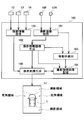
- FIG. 2 shows a rough internal configuration of the image display apparatus 100 of the present embodiment.
- the image display apparatus 100 of the present embodiment includes a captured image acquisition unit 101, a captured overhead image generation unit 102, a moving body detection unit 103, a captured overhead image storage unit 104, and a movement information acquisition unit 105. And a display image generation unit 106.
- these six “sections” are abstractions in which the interior of the image display apparatus 100 is classified for convenience, focusing on the function of the image display apparatus 100 displaying an image around the vehicle 1 on the display screen 11. This does not represent that the image display device 100 is physically divided into six parts. Therefore, these “units” can be realized as software components as computer programs executed by the CPU, or can be realized as hardware components as electronic circuits including LSIs and memories. Further, it can be realized by combining these.
- the captured image acquisition unit 101 is connected to the in-vehicle camera 10F and the in-vehicle camera 10R, and acquires a captured image obtained by capturing an area in front of the vehicle 1 from obliquely above from the in-vehicle camera 10F at a constant cycle (about 30 Hz).
- a captured image obtained by capturing an area behind the vehicle 1 from obliquely above is acquired at a constant period (about 30 Hz).
- the photographed bird's-eye view image generation unit 102 receives the images taken by the in-vehicle cameras 10F and 10R from the photographed image acquisition unit 101 and generates an overhead image. That is, the photographed image obtained by the in-vehicle camera 10F is an image obtained by photographing an area in front of the vehicle 1 from obliquely above, and the photographed image is obtained from above the vehicle 1 by performing line-of-sight conversion described later on this image. Such a bird's-eye view image is generated. Similarly, the image captured by the in-vehicle camera 10 ⁇ / b> R is an image obtained by capturing an area behind the vehicle 1 from obliquely above, and this image is converted into an overhead view image captured from above the vehicle 1.
- the photographing overhead image generation unit 102 is also referred to as a photographing overhead image generation device / means.
- an overhead image is generated not only in the front-rear direction area of the vehicle 1 but also in the left-right direction area of the vehicle 1 and displayed on the display screen 11.
- the bird's-eye view image displayed in the front-rear direction of the vehicle 1 is an image obtained by line-of-sight conversion of the current image captured by the in-vehicle cameras 10F and 10R.
- the bird's-eye view image displayed in the left-right direction of the vehicle 1 is an image synthesized from the past bird's-eye view images displayed in the front-rear direction of the vehicle 1 based on the movement information of the vehicle 1.
- the bird's-eye view image displayed in the front-rear direction of the vehicle 1 is referred to as a “shooting bird's-eye view image” in order to distinguish it from the synthesized bird's-eye view image displayed in the left-right direction of the vehicle 1.
- the term “overhead image” simply refers to an image viewed from above the vehicle 1, and accordingly, both the imaged bird's-eye view image and the history image correspond to the “overhead image”.
- the shooting bird's-eye view image generation unit 102 outputs the generated shooting bird's-eye view image to the moving object detection unit 103, the shooting bird's-eye view image storage unit 104, and the display image generation unit 106.
- the moving body detection unit 103 analyzes the shooting overhead image supplied from the shooting overhead image generation unit 102 and detects a moving body in the shooting overhead image.
- the moving object can be detected by comparing an image received in the past with a newly received image.
- the moving body detection unit 103 is described as detecting a moving body from the captured bird's-eye view image.
- the captured image acquisition unit 101 receives the in-vehicle camera 10F, A moving image in the captured image may be detected by receiving a captured image by 10R.
- the moving body detection unit 103 is also referred to as a moving body detection device / means.
- the photographic overhead image storage unit 104 stores the photographic overhead image supplied from the photographic overhead image generation unit 102. Further, when a moving body is detected by the moving body detection unit 103 in the captured bird's-eye view image, the position where the moving body is detected in the captured bird's-eye view image is also stored in association with the captured bird's-eye view image.
- the photographing overhead image storage unit 104 is also referred to as a photographing overhead image storage device / means.
- the moving body detection unit 103 detects a moving body using an image (photographed images by the in-vehicle cameras 10F and 10R) before the line-of-sight of the captured overhead image is not a captured overhead image, the captured image is captured. By performing line-of-sight conversion on the position of the moving body detected in the position, the position of the moving body in the captured bird's-eye view image can be obtained.
- the movement information acquisition unit 105 is connected to the steering angle sensor 12, the vehicle speed sensor 13, and the shift position sensor 14.
- the movement information acquisition unit 105 acquires movement information of the vehicle 1 based on the outputs of these sensors.
- the movement information of the vehicle 1 is information such as whether the vehicle 1 is moving forward, backward, or stopped, whether the vehicle 1 is moving straight, or whether it is turning right Whether the vehicle is turning left, or if it is turning, information on the magnitude of the turn, information on the moving speed of the vehicle 1, and the like.
- the movement information acquisition unit 105 outputs the acquired movement information of the vehicle 1 to the display image generation unit 106.
- the movement information acquisition unit 105 is also referred to as movement information acquisition device / means.
- the display image generation unit 106 uses the shooting overhead image from the shooting overhead image generation unit 102, the movement information from the movement information acquisition unit 105, and the past shooting overhead image stored in the shooting overhead image storage unit 104. Thus, a bird's-eye view image of the peripheral region over the entire circumference of the vehicle 1 is generated and displayed on the display screen 11.
- the front and rear areas of the vehicle 1 are the imaging areas of the in-vehicle cameras 10F and 10R, and therefore, an overhead image (captured overhead image) obtained by line-of-sight conversion of the images captured by the in-vehicle cameras 10F and 10R may be displayed.
- the areas in the right and left directions of the vehicle 1 are blind spots of the in-vehicle cameras 10F and 10R, a bird's-eye view image cannot be obtained simply by performing line-of-sight conversion on the images captured by the in-vehicle cameras 10F and 10R.
- the display image generation unit 106 is also referred to as a shooting overhead image display unit / device / means or a history image display unit / device / means.
- a method for generating a bird's-eye view image in an area in the left-right direction of the vehicle 1 will be described.
- a photographed bird's-eye view image is generated by performing line-of-sight conversion on images taken by the in-vehicle cameras 10F and 10R.
- a method will be described.
- a method for generating a bird's-eye view image in an area in the left-right direction of the vehicle 1 will be described.
- FIG. 3A shows a plurality of round marks drawn in a lattice pattern at equal intervals on the ground in front of the vehicle 1 as viewed from above the vehicle 1.
- two alternate long and short dash lines extending obliquely from the in-vehicle camera 10F represent the boundary between the imaging region and the blind spot region of the in-vehicle camera 10F.
- a round mark displayed with a thick solid line indicates that the mark is within the imaging region of the in-vehicle camera 10F
- a round mark displayed with a thin broken line indicates that the mark is mounted on the vehicle. It represents that it is in the blind spot area of the camera 10F.
- the in-vehicle camera 10F (or the in-vehicle camera 10R) images such a ground from obliquely above.
- FIG. 3B shows a captured image obtained by the in-vehicle camera 10F.
- the photographed image shows a mark on the ground that exists within the photographing range of the in-vehicle camera 10F.
- the mark a on the photographed image is the mark A on the ground in FIG. 3A
- the mark b on the photographed image is the mark B on the ground.
- the mark c and the mark d on the photographed image are the marks C and D on the ground.
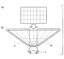
- the captured image shown in FIG. 4A is converted into an overhead image as shown in FIG.
- the bird's-eye view image thus obtained becomes an image that spreads in the left-right direction as the position is further away. This is because the imaging range of the in-vehicle camera 10F (or in-vehicle camera 10R) is widened on both the left and right sides (see FIG. 3A).
- FIG. 4B a region that extends to the left in the overhead image is displayed as region L, and a region that extends to the right is displayed as region R.
- both the region L and the region R are in the imaging region of the in-vehicle camera 10F.
- the region L becomes a blind spot region in the left direction of the vehicle 1
- the region R becomes a blind spot region in the right direction of the vehicle 1.
- a bird's-eye view image (shooting bird's-eye view image) obtained by line-of-sight conversion of the photographed image of the in-vehicle camera 10F is stored, and the current blind spot area is selected from the past photographed bird's-eye images as the vehicle 1 moves.
- the image (history image) of the part corresponding to is cut out and displayed. In this way, it is possible to display a bird's-eye view image also in the left and right area of the vehicle 1.
- the above is the basic concept of displaying a bird's-eye view image of the left and right region of the vehicle 1 using the history image.
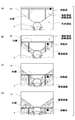
- FIG. 5 shows a state in which the bird's-eye view around the vehicle 1 displayed on the display screen 11 changes as the vehicle 1 moves forward.
- the front portion of the vehicle 1 is enlarged and displayed.
- two white lines are drawn on the ground in front of the vehicle 1 in parallel to the traveling direction of the vehicle 1, and one line is perpendicular to the traveling direction of the vehicle 1 on the back side.
- the white line is drawn. Further, here, it is assumed that a photographed bird's-eye view image generated by line-of-sight conversion in the past has not yet been stored.
- FIG. 5A shows an overhead view image around the vehicle 1 displayed on the display screen 11 first.
- a shooting overhead image generated by line-of-sight conversion of a captured image of the in-vehicle camera 10 ⁇ / b> F is displayed in the imaging area in front of the vehicle 1.
- a moving object is shown on the white line.
- no history image is displayed in the left and right blind spot areas of the vehicle 1.
- FIG. 5B shows an overhead view image around the vehicle 1 displayed on the display screen 11 with the vehicle 1 slightly advanced.
- the position of the white line is slightly closer to the vehicle 1 as the vehicle 1 slightly moves forward.
- the moving body that was on the white line has moved to the near side of the white line.
- the captured bird's-eye view image is an image obtained by line-of-sight conversion of the current image photographed by the in-vehicle camera 10F
- the fact that the moving body is in front of the white line in the photographed bird's-eye view image is also the photographed image of the in-vehicle camera 10F. It can be considered that the moving body is in front of the white line. Therefore, on the display screen 11 shown in FIG. 5B, it can be considered that the position where the moving object actually exists is correctly displayed.
- the left and right blind spot areas of the vehicle 1 are images (corresponding to images) of the corresponding part from the past photographing bird's-eye images displayed in FIG. Image) is cut out and displayed.
- the history image is displayed with diagonal lines in order to distinguish the captured overhead image from the history image.
- FIG. 5C shows a bird's-eye view of the surroundings of the vehicle 1 displayed on the display screen 11 in a state where the vehicle 1 has further advanced a little.
- a white line ahead of the vehicle 1 is displayed at a position closer to the vehicle 1.
- the white line in the imaging area in front of the vehicle 1 is a slight part, and most of the white line exists in the left and right blind spot areas of the vehicle 1.
- the blind spot area since a history image obtained by cutting out the corresponding portion from the past shooting overhead image displayed in FIG. 5A or 5B is displayed, You can confirm the position of the white line with.
- the moving object is also displayed on the display screen 11 shown in FIG.
- the position of the moving body shown in FIG. 5C is not changed from the position of the moving body shown in FIG. This is because the moving body image in FIG. 5C is a history image cut out from the image displayed in the photographic overhead image in FIG. 5B, and the image in FIG. 5C is displayed. It is because it is a past image from the point of view.
- the moving body is actually moving further from the time when the image of FIG. 5B is displayed. If the moving direction and moving speed of the moving body do not change, the moving body at the time when the image of FIG. 5C is displayed should be present at the position of the white circle indicated by the broken line in the figure. . That is, in this case, the driver misunderstands that the position of the moving body is farther than the actual position.
- FIG. 5D shows a bird's-eye view image around the vehicle 1 displayed on the display screen 11 in a state where the vehicle 1 has advanced a little further from the state shown in FIG. 5C.
- the entire white line is displayed as a history image.
- a moving object is also displayed in the image of FIG. 5D, but since this moving object is displayed as a history image, the position of the moving object with respect to the white line is displayed in the image of FIG. 5B. It has not changed from where it was. However, if the moving direction and moving speed of the moving body do not change, the moving body should actually exist at the position of the white circle indicated by the broken line in the figure.
- the moving direction and moving speed of the moving body are not always constant. Therefore, it is difficult to estimate the actual position of the moving body.
- the image display device 100 of the present embodiment has the following: Execute image display processing.
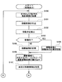
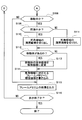
- Image display processing of this embodiment 6 and 7 show flowcharts of image display processing executed by the image display apparatus 100 of the present embodiment.
- each section is expressed as S100, for example.
- each section can be divided into a plurality of subsections, while a plurality of sections can be combined into one section.
- each section can be referred to as a device, module, or means.
- each of the above sections or a combination thereof includes not only (i) a section of software combined with a hardware unit (eg, a computer), but also (ii) hardware (eg, an integrated circuit, As a section of (wiring logic circuit), it can be realized with or without the function of related devices.
- the hardware section can be included inside the microcomputer.
- the image display process when the image display process is started, first, captured images of the front and rear of the vehicle 1 are acquired from the in-vehicle camera 10F and the in-vehicle camera 10R (S100). Then, the captured images acquired from the in-vehicle cameras 10F and 10R are line-of-sight-converted to generate shooting overhead images for the shooting areas in front and rear of the vehicle 1 (S101).
- a moving body is detected from the overhead images taken from the front and rear of the vehicle 1 (S102). Any known method may be used to detect the moving object. And it is judged whether the mobile body was detected (S103). As a result, when the moving object is not detected (S103: NO), the front and rear shooting overhead images are stored in the memory in a state where the shooting timing can be identified (for example, together with the time stamp) (S104). . On the other hand, when the moving body is detected (S103: YES), the photographing overhead image and the position of the moving body in the photographing overhead image are stored in the memory in a state where the photographing timing can be identified ( S105).
- the position of the shooting bird's-eye image and the moving object is determined for the front shooting bird's-eye image. It memorize
- the frame memory is a memory area used for displaying an image on the display screen 11.
- An image displayed on the display screen 11 is generated on the frame memory.
- the image is displayed on the display screen 11 by outputting the data in the frame memory as a video signal.
- Each address on the frame memory corresponds to each pixel on the display screen 11.
- the front bird's-eye view image is written in each address of the frame memory corresponding to the shooting area of the in-vehicle camera 10F on the display screen 11, and the rear address is written in each address of the frame memory corresponding to the shooting area of the in-vehicle camera 10R.
- the image display device 100 acquires movement information (also referred to as movement data) of the vehicle 1 (S107).
- the movement information of the vehicle 1 is information (or data) acquired from the steering angle sensor 12, the vehicle speed sensor 13, the shift position sensor 14, or the like.
- the display mode of the moving object in the history image is changed to a special mode different from the normal mode (S113).
- the color of the moving object in the history image is changed (for example, changed to red) and displayed, the moving object is displayed surrounded by a red frame or a white frame, and the moving object image is displayed in advance. It replaces the stored graphic image and displays it.
- the operation for changing the display mode of the moving object is not performed.
- the history image obtained in this way is written in the frame memory corresponding to the blind spot area of the in-vehicle camera 10F and the in-vehicle camera 10R on the display screen 11 (S114).
- the history image changed to the special mode is written.
- the image displayed on the display screen 11 is displayed on the frame memory by writing the history image. Complete.
- the image display device 100 outputs the image on the frame memory to the display screen 11 (S115). As a result, a bird's-eye view image as if the periphery of the vehicle 1 was viewed from above is displayed on the display screen 11.
- the series of processing for writing the history image (S109 to S114) is not performed, and the image on the frame memory is output to the display screen 11. (S115).
- the display screen 11 displays an image in which only the captured bird's-eye images displayed before and after the vehicle 1 are updated.
- the history image is displayed in the blind spot area on the display screen 11.
- the history image remaining on the frame memory is displayed in the blind spot area of the display screen 11 for a predetermined time after the vehicle 1 is stopped, but after the predetermined time has elapsed, the history image on the frame memory is displayed. May be deleted so that the history image is not displayed on the display screen 11.
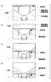
- FIG. 8 illustrates a bird's-eye view image displayed on the display screen 11 by the image display process of the present embodiment described above.
- FIG. 8 illustrates a bird's-eye view image displayed on the display screen 11 by the image display process of the present embodiment described above.
- two white lines parallel to the traveling direction of the vehicle 1 and right angles to the two white lines are present on the ground in front of the vehicle 1. It is assumed that a single white line is drawn. Further, it is assumed that the moving body is moving in the same manner as in the case shown in FIG. In FIG. 5, the history image is displayed with a diagonal line, but in FIG. 8, the history image is displayed without a diagonal line in order to avoid complexity.
- the moving body when the moving body enters the blind spot area and is displayed as a history image, in this embodiment, the moving body is displayed in a mode different from the normal mode.
- the moving body is displayed in a color different from normal, such as red or yellow. For this reason, the driver thinks what happened and confirms the surroundings of the vehicle 1 by looking directly at the moving body, not through the display screen 11, so that the correct position of the moving body is recognized. Can do.
- the moving body is displayed on the display screen 11 in a mode different from the normal mode.
- the driver tries to visually confirm the moving body, and as a result, the correct position of the moving body is obtained. Recognize For this reason, even if the moving body is not displayed at the correct position on the display screen 11, it is possible to prevent the driver from misunderstanding the position of the moving body.
- FIG. 9 shows a modification in which a history image is displayed in such a mode.
- the moving body is present in the captured bird's-eye view image, and is not present in the left-right history image of the vehicle 1. For this reason, any history image in the left-right direction is displayed in the same mode as in the normal mode, similar to the captured bird's-eye view image.
- the history image on the right side of the vehicle 1 is displayed in a mode different from the normal mode, for example, a reddish color or a yellowish color.
- the left side history image of the vehicle 1 is displayed in the same mode as usual.
- the history image on the right side of the vehicle 1 is displayed on the display screen 11 in a mode different from the normal mode, so it is thought that what has happened, and the region on the right side of the vehicle 1 is directly checked by visual observation. . As a result, it is possible to recognize the correct position of the moving body.
- the history image on the side where the moving body is present with respect to the vehicle 1 is displayed in a mode different from the normal mode. Therefore, for example, as shown in FIGS. 9B to 9D, when there is a portion where no history image is displayed in the blind spot area on the side of the vehicle 1, only the portion of the history image is normally displayed. Is displayed in a different mode.
- the entire blind spot area on the side where the moving object exists may be displayed in a mode different from the normal mode.
- the history image on the side where the moving body exists is displayed in a mode different from the normal mode, and the mobile body itself is displayed in a mode different from the normal mode.
Abstract
L'invention concerne un appareil d'affichage servant à afficher une image de périphérie de véhicule, qui convertit en ligne de vision une image capturée par une caméra montée sur véhicule pour générer une image capturée du dessus, et qui stocke l'image capturée du dessus ainsi générée. Si un corps mobile quelconque est présent dans l'image capturée du dessus, l'appareil d'affichage stocke également la position du corps mobile dans l'image capturée du dessus. L'appareil d'affichage acquiert des informations de mouvement de véhicule, découpe, dans l'image du dessus capturée stockée, une partie de celle-ci qui est une image d'historique obtenue par capture de l'image d'une zone d'angle mort du véhicule, et affiche, sur un écran d'affichage, l'image d'historique en même temps que l'image capturée du dessus. À ce moment-là, si le corps mobile est présent dans l'image d'historique, l'appareil d'affichage affiche le corps mobile dans un mode d'affichage différent du mode d'affichage utilisé dans le cas où le corps mobile est présent dans l'image capturée du dessus.
Priority Applications (2)
| Application Number | Priority Date | Filing Date | Title |
|---|---|---|---|
| DE112015000763.6T DE112015000763T5 (de) | 2014-02-12 | 2015-01-22 | Fahrzeugumgebungsbildanzeigevorrichtung undFahrzeugumgebungsbildanzeigeverfahren |
| CN201580008224.XA CN106031166B (zh) | 2014-02-12 | 2015-01-22 | 车辆周边图像显示装置和车辆周边图像显示方法 |
Applications Claiming Priority (2)
| Application Number | Priority Date | Filing Date | Title |
|---|---|---|---|
| JP2014024013A JP6375633B2 (ja) | 2014-02-12 | 2014-02-12 | 車両周辺画像表示装置、車両周辺画像表示方法 |
| JP2014-024013 | 2014-02-12 |
Publications (1)
| Publication Number | Publication Date |
|---|---|
| WO2015122124A1 true WO2015122124A1 (fr) | 2015-08-20 |
Family
ID=53799877
Family Applications (1)
| Application Number | Title | Priority Date | Filing Date |
|---|---|---|---|
| PCT/JP2015/000279 WO2015122124A1 (fr) | 2014-02-12 | 2015-01-22 | Appareil d'affichage d'image de périphérie de véhicule et procédé d'affichage d'image de périphérie de véhicule |
Country Status (4)
| Country | Link |
|---|---|
| JP (1) | JP6375633B2 (fr) |
| CN (1) | CN106031166B (fr) |
| DE (1) | DE112015000763T5 (fr) |
| WO (1) | WO2015122124A1 (fr) |
Families Citing this family (5)
| Publication number | Priority date | Publication date | Assignee | Title |
|---|---|---|---|---|
| DE102017130173A1 (de) * | 2017-02-24 | 2018-08-30 | Denso Ten Limited | Ladeunterstützungsvorrichtung |
| JP6859216B2 (ja) * | 2017-07-03 | 2021-04-14 | トヨタ自動車株式会社 | 車両周辺表示装置 |
| JP6741364B2 (ja) | 2017-08-03 | 2020-08-19 | 三菱電機株式会社 | 車両周辺画像表示装置および車両周辺画像表示方法 |
| WO2020213111A1 (fr) * | 2019-04-18 | 2020-10-22 | 三菱電機株式会社 | Dispositif de génération d'image d'environnement de véhicule, système d'affichage d'environnement de véhicule et procédé d'affichage d'environnement de véhicule |
| JP7299193B2 (ja) * | 2020-04-16 | 2023-06-27 | トヨタ自動車株式会社 | 表示制御装置、表示制御方法及びプログラム |
Citations (6)
| Publication number | Priority date | Publication date | Assignee | Title |
|---|---|---|---|---|
| JP2003030627A (ja) * | 2001-07-16 | 2003-01-31 | Denso Corp | 車両周辺画像処理装置及び記録媒体 |
| JP2003191810A (ja) * | 2001-12-26 | 2003-07-09 | Denso Corp | 車両周辺監視システム及び車両移動状態検出装置 |
| JP2004260694A (ja) * | 2003-02-27 | 2004-09-16 | Nippon Soken Inc | 車両周辺画像処理システム |
| JP2005138716A (ja) * | 2003-11-06 | 2005-06-02 | Denso Corp | 駐車支援装置 |
| JP2006279752A (ja) * | 2005-03-30 | 2006-10-12 | Denso Corp | 車両直下画像表示制御装置および車両直下画像表示制御プログラム |
| JP2008227646A (ja) * | 2007-03-09 | 2008-09-25 | Clarion Co Ltd | 障害物検知装置 |
Family Cites Families (8)
| Publication number | Priority date | Publication date | Assignee | Title |
|---|---|---|---|---|
| JP4156214B2 (ja) * | 2001-06-13 | 2008-09-24 | 株式会社デンソー | 車両周辺画像処理装置及び記録媒体 |
| JP4657765B2 (ja) * | 2005-03-09 | 2011-03-23 | 三菱自動車工業株式会社 | ノーズビューシステム |
| JP2007076425A (ja) * | 2005-09-12 | 2007-03-29 | Aisin Aw Co Ltd | 駐車支援方法及び駐車支援装置 |
| JP2007249814A (ja) * | 2006-03-17 | 2007-09-27 | Denso Corp | 画像処理装置及び画像処理プログラム |
| JP4038529B1 (ja) * | 2006-12-05 | 2008-01-30 | 株式会社ナビタイムジャパン | ナビゲーションシステム、携帯端末装置および周辺画像表示方法 |
| JP5035284B2 (ja) * | 2009-03-25 | 2012-09-26 | 株式会社日本自動車部品総合研究所 | 車両周辺表示装置 |
| US9418556B2 (en) * | 2010-12-30 | 2016-08-16 | Wise Automotive Corporation | Apparatus and method for displaying a blind spot |
| JP5962927B2 (ja) * | 2011-09-30 | 2016-08-03 | パナソニックIpマネジメント株式会社 | 俯瞰画像生成装置、俯瞰画像生成方法、および俯瞰画像生成プログラム |
-
2014
- 2014-02-12 JP JP2014024013A patent/JP6375633B2/ja active Active
-
2015
- 2015-01-22 CN CN201580008224.XA patent/CN106031166B/zh active Active
- 2015-01-22 WO PCT/JP2015/000279 patent/WO2015122124A1/fr active Application Filing
- 2015-01-22 DE DE112015000763.6T patent/DE112015000763T5/de not_active Withdrawn
Patent Citations (6)
| Publication number | Priority date | Publication date | Assignee | Title |
|---|---|---|---|---|
| JP2003030627A (ja) * | 2001-07-16 | 2003-01-31 | Denso Corp | 車両周辺画像処理装置及び記録媒体 |
| JP2003191810A (ja) * | 2001-12-26 | 2003-07-09 | Denso Corp | 車両周辺監視システム及び車両移動状態検出装置 |
| JP2004260694A (ja) * | 2003-02-27 | 2004-09-16 | Nippon Soken Inc | 車両周辺画像処理システム |
| JP2005138716A (ja) * | 2003-11-06 | 2005-06-02 | Denso Corp | 駐車支援装置 |
| JP2006279752A (ja) * | 2005-03-30 | 2006-10-12 | Denso Corp | 車両直下画像表示制御装置および車両直下画像表示制御プログラム |
| JP2008227646A (ja) * | 2007-03-09 | 2008-09-25 | Clarion Co Ltd | 障害物検知装置 |
Also Published As
| Publication number | Publication date |
|---|---|
| DE112015000763T5 (de) | 2016-11-03 |
| JP2015154125A (ja) | 2015-08-24 |
| JP6375633B2 (ja) | 2018-08-22 |
| CN106031166B (zh) | 2018-12-25 |
| CN106031166A (zh) | 2016-10-12 |
Similar Documents
| Publication | Publication Date | Title |
|---|---|---|
| WO2016002163A1 (fr) | Dispositif d'affichage d'image et procédé d'affichage d'image | |
| JP5143235B2 (ja) | 制御装置および車両周囲監視装置 | |
| JP5729158B2 (ja) | 駐車支援装置および駐車支援方法 | |
| JP7069548B2 (ja) | 周辺監視装置 | |
| JP6213567B2 (ja) | 予測進路提示装置及び予測進路提示方法 | |
| US20200082185A1 (en) | Periphery monitoring device | |
| JP2005112004A (ja) | 車両後退支援装置および方法 | |
| WO2015122124A1 (fr) | Appareil d'affichage d'image de périphérie de véhicule et procédé d'affichage d'image de périphérie de véhicule | |
| US10099617B2 (en) | Driving assistance device and driving assistance method | |
| JP6586849B2 (ja) | 情報表示装置及び情報表示方法 | |
| JP5516988B2 (ja) | 駐車支援装置 | |
| JP2006268076A (ja) | 運転支援システム | |
| US20170259830A1 (en) | Moving amount derivation apparatus | |
| JP6471522B2 (ja) | カメラパラメータ調整装置 | |
| JP6778620B2 (ja) | 区画線検出装置、区画線検出システム、及び区画線検出方法 | |
| WO2015133072A1 (fr) | Dispositif et procédé d'affichage d'image de périphérie de véhicule | |
| JP2015171106A (ja) | 車両周辺画像表示装置、車両周辺画像表示方法 | |
| JP6327115B2 (ja) | 車両周辺画像表示装置、車両周辺画像表示方法 | |
| JP2022023870A (ja) | 表示制御装置 | |
| JP2007134961A (ja) | 車両検出装置及びこれを用いた車両用表示装置 | |
| JP2005182305A (ja) | 車両走行支援装置 | |
| WO2017122688A1 (fr) | Dispositif de détection d'anomalie d'objectif de caméra embarquée | |
| JP2008294616A (ja) | 運転支援システム及び車両 | |
| JP4857159B2 (ja) | 車両運転支援装置 | |
| JP7137356B2 (ja) | 車載用故障検出装置、及び故障検出方法 |
Legal Events
| Date | Code | Title | Description |
|---|---|---|---|
| 121 | Ep: the epo has been informed by wipo that ep was designated in this application |
Ref document number: 15749074 Country of ref document: EP Kind code of ref document: A1 |
|
| WWE | Wipo information: entry into national phase |
Ref document number: 112015000763 Country of ref document: DE |
|
| 122 | Ep: pct application non-entry in european phase |
Ref document number: 15749074 Country of ref document: EP Kind code of ref document: A1 |