WO2015122124A1 - Vehicle periphery image display apparatus and vehicle periphery image display method - Google Patents
Vehicle periphery image display apparatus and vehicle periphery image display method Download PDFInfo
- Publication number
- WO2015122124A1 WO2015122124A1 PCT/JP2015/000279 JP2015000279W WO2015122124A1 WO 2015122124 A1 WO2015122124 A1 WO 2015122124A1 JP 2015000279 W JP2015000279 W JP 2015000279W WO 2015122124 A1 WO2015122124 A1 WO 2015122124A1
- Authority
- WO
- WIPO (PCT)
- Prior art keywords
- image
- vehicle
- bird
- eye view
- moving body
- Prior art date
Links
- 238000000034 method Methods 0.000 title claims description 23
- 240000004050 Pentaglottis sempervirens Species 0.000 claims description 97
- 235000004522 Pentaglottis sempervirens Nutrition 0.000 claims description 97
- 230000002093 peripheral effect Effects 0.000 claims description 17
- 238000006243 chemical reaction Methods 0.000 claims description 15
- 238000001514 detection method Methods 0.000 claims description 10
- 230000015654 memory Effects 0.000 description 22
- 230000008569 process Effects 0.000 description 10
- 238000003384 imaging method Methods 0.000 description 8
- 230000008859 change Effects 0.000 description 3
- 230000004048 modification Effects 0.000 description 3
- 238000012986 modification Methods 0.000 description 3
- 230000000007 visual effect Effects 0.000 description 3
- 238000005516 engineering process Methods 0.000 description 2
- 230000006870 function Effects 0.000 description 2
- 230000005540 biological transmission Effects 0.000 description 1
- 238000004590 computer program Methods 0.000 description 1
- 238000010586 diagram Methods 0.000 description 1
Images


Classifications
-
- B—PERFORMING OPERATIONS; TRANSPORTING
- B60—VEHICLES IN GENERAL
- B60R—VEHICLES, VEHICLE FITTINGS, OR VEHICLE PARTS, NOT OTHERWISE PROVIDED FOR
- B60R1/00—Optical viewing arrangements; Real-time viewing arrangements for drivers or passengers using optical image capturing systems, e.g. cameras or video systems specially adapted for use in or on vehicles
- B60R1/20—Real-time viewing arrangements for drivers or passengers using optical image capturing systems, e.g. cameras or video systems specially adapted for use in or on vehicles
- B60R1/22—Real-time viewing arrangements for drivers or passengers using optical image capturing systems, e.g. cameras or video systems specially adapted for use in or on vehicles for viewing an area outside the vehicle, e.g. the exterior of the vehicle
- B60R1/23—Real-time viewing arrangements for drivers or passengers using optical image capturing systems, e.g. cameras or video systems specially adapted for use in or on vehicles for viewing an area outside the vehicle, e.g. the exterior of the vehicle with a predetermined field of view
- B60R1/27—Real-time viewing arrangements for drivers or passengers using optical image capturing systems, e.g. cameras or video systems specially adapted for use in or on vehicles for viewing an area outside the vehicle, e.g. the exterior of the vehicle with a predetermined field of view providing all-round vision, e.g. using omnidirectional cameras
-
- G—PHYSICS
- G06—COMPUTING; CALCULATING OR COUNTING
- G06T—IMAGE DATA PROCESSING OR GENERATION, IN GENERAL
- G06T3/00—Geometric image transformation in the plane of the image
- G06T3/40—Scaling the whole image or part thereof
- G06T3/4038—Scaling the whole image or part thereof for image mosaicing, i.e. plane images composed of plane sub-images
-
- H—ELECTRICITY
- H04—ELECTRIC COMMUNICATION TECHNIQUE
- H04N—PICTORIAL COMMUNICATION, e.g. TELEVISION
- H04N7/00—Television systems
- H04N7/18—Closed-circuit television [CCTV] systems, i.e. systems in which the video signal is not broadcast
-
- B—PERFORMING OPERATIONS; TRANSPORTING
- B60—VEHICLES IN GENERAL
- B60R—VEHICLES, VEHICLE FITTINGS, OR VEHICLE PARTS, NOT OTHERWISE PROVIDED FOR
- B60R2300/00—Details of viewing arrangements using cameras and displays, specially adapted for use in a vehicle
- B60R2300/30—Details of viewing arrangements using cameras and displays, specially adapted for use in a vehicle characterised by the type of image processing
-
- B—PERFORMING OPERATIONS; TRANSPORTING
- B60—VEHICLES IN GENERAL
- B60R—VEHICLES, VEHICLE FITTINGS, OR VEHICLE PARTS, NOT OTHERWISE PROVIDED FOR
- B60R2300/00—Details of viewing arrangements using cameras and displays, specially adapted for use in a vehicle
- B60R2300/60—Details of viewing arrangements using cameras and displays, specially adapted for use in a vehicle characterised by monitoring and displaying vehicle exterior scenes from a transformed perspective
- B60R2300/607—Details of viewing arrangements using cameras and displays, specially adapted for use in a vehicle characterised by monitoring and displaying vehicle exterior scenes from a transformed perspective from a bird's eye viewpoint
-
- B—PERFORMING OPERATIONS; TRANSPORTING
- B60—VEHICLES IN GENERAL
- B60R—VEHICLES, VEHICLE FITTINGS, OR VEHICLE PARTS, NOT OTHERWISE PROVIDED FOR
- B60R2300/00—Details of viewing arrangements using cameras and displays, specially adapted for use in a vehicle
- B60R2300/70—Details of viewing arrangements using cameras and displays, specially adapted for use in a vehicle characterised by an event-triggered choice to display a specific image among a selection of captured images
Definitions
- This disclosure relates to a display device (Display Apparatus) and a display method (Display Method) for displaying an image obtained by photographing a peripheral region of a vehicle using an in-vehicle camera on a display screen.
- Patent Document 1 a technique for displaying an overhead image of a peripheral region in the front-rear and left-right directions of the vehicle has been proposed (Patent Document 1) even though the vehicle-mounted cameras are not mounted on the left and right sides of the vehicle.
- Patent Document 1 a technique for displaying an overhead image of a peripheral region in the front-rear and left-right directions of the vehicle.
- the bird's-eye view image obtained from the front vehicle-mounted camera also includes an image of a region diagonally forward in the left and right directions of the vehicle.
- This diagonally forward area eventually becomes an area in the left-right direction of the vehicle as the vehicle moves forward. Therefore, if an image of a region diagonally forward of the vehicle included in the overhead image is stored, it can be used as an overhead image in the left-right direction of the vehicle after the vehicle has advanced.
- the image of the corresponding part may be cut out and used from the overhead view image stored before the forward movement. In this way, it is possible to display a bird's-eye view of the surrounding area in the front-rear and left-right directions of the vehicle without mounting on-vehicle cameras on the left and right sides of the vehicle.
- the bird's-eye view image displayed in the left-right direction of the vehicle is a past bird's-eye view image that was actually taken a little while ago. Therefore, an image cut out from a past bird's-eye view image and displayed in the left-right direction of the vehicle is called a “history image”.
- the positional relationship between the host vehicle and the moving body and the positional relationship change by changing the line of sight of the image of the on-vehicle camera and displaying the overhead image. It is possible to correctly display the state of going. After that, when the moving body enters the blind spot of the in-vehicle camera as the vehicle moves, the overhead image obtained by converting the line of sight of the in-vehicle camera cannot display the moving body. Need arises. However, since the history image is an image taken a while ago, the correct position of the moving body is not always displayed.
- the position of the moving object displayed using the history image gradually moves in the opposite direction to the traveling direction of the vehicle as the vehicle progresses, but moves in the opposite direction by the amount of movement of the vehicle. Because it only does, it will appear as if the moving body has stopped against the ground. For this reason, even if the moving body is approaching to the immediate vicinity of the vehicle, the moving body is stopped, so that it may be misunderstood by the driver unless it contacts the vehicle.
- An object is to provide a technique capable of displaying an image.
- a vehicle peripheral image display device and a vehicle peripheral image display method are provided as follows.
- a photographic overhead view image is generated by performing line-of-sight conversion on a captured image obtained by the in-vehicle camera, and the obtained photographic overhead view image is stored. Further, when a moving body is present in the photographic overhead image, the position of the moving body in the photographic overhead image is also stored. Then, movement information relating to the amount of movement of the vehicle is acquired, and a history image, which is an image of a portion where the blind spot area of the vehicle is photographed, is cut out from the stored photographing bird's-eye view image and displayed together with the photographing bird's-eye view image Display above. At this time, if a moving object exists in the history image, the moving object is displayed in a display mode different from that in the case where the moving object exists in the captured overhead image.
- the driver can recognize that the moving body is displayed by the history image.
- the driver tries to confirm the moving body by, for example, direct visual observation, so that misunderstanding of the position of the moving body can be avoided.
- FIG. 1 shows a vehicle 1 (also referred to as a host vehicle) equipped with an image display device 100.
- the image display device 100 is also referred to as a vehicle periphery image display device.
- the vehicle 1 includes an in-vehicle camera 10F mounted in front of the vehicle 1, an in-vehicle camera 10R mounted in the rear of the vehicle 1, a display screen 11 mounted in the vehicle interior, and an image display device 100.
- the vehicle-mounted cameras 10F and 10R are described as being mounted on the front and rear of the vehicle 1, respectively.
- the vehicle 1 mounted with either the vehicle-mounted camera 10F or the vehicle-mounted camera 10R is described. Also, the present disclosure can be applied.
- the image display device 100 When the image display device 100 receives an image of the periphery of the vehicle 1 taken by the in-vehicle cameras 10F and 10R, the image display device 100 converts the image into an overhead view image taken from above the vehicle 1, and then displays the obtained image. It is displayed on the screen 11.
- the vehicle 1 is also equipped with a steering angle sensor 12 for detecting the steering angle of the steering handle 2, a vehicle speed sensor 13 for detecting the vehicle speed, a shift position sensor 14 for detecting a shift position of a transmission (not shown), and the like. Yes.
- the outputs of the steering angle sensor 12, the vehicle speed sensor 13, and the shift position sensor 14 are input to the image display device 100, and the image display device 100 determines the movement amount (movement speed and movement direction) of the vehicle 1 based on these outputs. ) Related movement information.
- the image display apparatus 100 is based on the movement information of the vehicle 1 and the bird's-eye view images obtained by the in-vehicle cameras 10F and 10R.
- a bird's-eye view image for (region) is generated and displayed on the display screen 11.
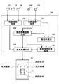
- FIG. 2 shows a rough internal configuration of the image display apparatus 100 of the present embodiment.
- the image display apparatus 100 of the present embodiment includes a captured image acquisition unit 101, a captured overhead image generation unit 102, a moving body detection unit 103, a captured overhead image storage unit 104, and a movement information acquisition unit 105. And a display image generation unit 106.
- these six “sections” are abstractions in which the interior of the image display apparatus 100 is classified for convenience, focusing on the function of the image display apparatus 100 displaying an image around the vehicle 1 on the display screen 11. This does not represent that the image display device 100 is physically divided into six parts. Therefore, these “units” can be realized as software components as computer programs executed by the CPU, or can be realized as hardware components as electronic circuits including LSIs and memories. Further, it can be realized by combining these.
- the captured image acquisition unit 101 is connected to the in-vehicle camera 10F and the in-vehicle camera 10R, and acquires a captured image obtained by capturing an area in front of the vehicle 1 from obliquely above from the in-vehicle camera 10F at a constant cycle (about 30 Hz).
- a captured image obtained by capturing an area behind the vehicle 1 from obliquely above is acquired at a constant period (about 30 Hz).
- the photographed bird's-eye view image generation unit 102 receives the images taken by the in-vehicle cameras 10F and 10R from the photographed image acquisition unit 101 and generates an overhead image. That is, the photographed image obtained by the in-vehicle camera 10F is an image obtained by photographing an area in front of the vehicle 1 from obliquely above, and the photographed image is obtained from above the vehicle 1 by performing line-of-sight conversion described later on this image. Such a bird's-eye view image is generated. Similarly, the image captured by the in-vehicle camera 10 ⁇ / b> R is an image obtained by capturing an area behind the vehicle 1 from obliquely above, and this image is converted into an overhead view image captured from above the vehicle 1.
- the photographing overhead image generation unit 102 is also referred to as a photographing overhead image generation device / means.
- an overhead image is generated not only in the front-rear direction area of the vehicle 1 but also in the left-right direction area of the vehicle 1 and displayed on the display screen 11.
- the bird's-eye view image displayed in the front-rear direction of the vehicle 1 is an image obtained by line-of-sight conversion of the current image captured by the in-vehicle cameras 10F and 10R.
- the bird's-eye view image displayed in the left-right direction of the vehicle 1 is an image synthesized from the past bird's-eye view images displayed in the front-rear direction of the vehicle 1 based on the movement information of the vehicle 1.
- the bird's-eye view image displayed in the front-rear direction of the vehicle 1 is referred to as a “shooting bird's-eye view image” in order to distinguish it from the synthesized bird's-eye view image displayed in the left-right direction of the vehicle 1.
- the term “overhead image” simply refers to an image viewed from above the vehicle 1, and accordingly, both the imaged bird's-eye view image and the history image correspond to the “overhead image”.
- the shooting bird's-eye view image generation unit 102 outputs the generated shooting bird's-eye view image to the moving object detection unit 103, the shooting bird's-eye view image storage unit 104, and the display image generation unit 106.
- the moving body detection unit 103 analyzes the shooting overhead image supplied from the shooting overhead image generation unit 102 and detects a moving body in the shooting overhead image.
- the moving object can be detected by comparing an image received in the past with a newly received image.
- the moving body detection unit 103 is described as detecting a moving body from the captured bird's-eye view image.
- the captured image acquisition unit 101 receives the in-vehicle camera 10F, A moving image in the captured image may be detected by receiving a captured image by 10R.
- the moving body detection unit 103 is also referred to as a moving body detection device / means.
- the photographic overhead image storage unit 104 stores the photographic overhead image supplied from the photographic overhead image generation unit 102. Further, when a moving body is detected by the moving body detection unit 103 in the captured bird's-eye view image, the position where the moving body is detected in the captured bird's-eye view image is also stored in association with the captured bird's-eye view image.
- the photographing overhead image storage unit 104 is also referred to as a photographing overhead image storage device / means.
- the moving body detection unit 103 detects a moving body using an image (photographed images by the in-vehicle cameras 10F and 10R) before the line-of-sight of the captured overhead image is not a captured overhead image, the captured image is captured. By performing line-of-sight conversion on the position of the moving body detected in the position, the position of the moving body in the captured bird's-eye view image can be obtained.
- the movement information acquisition unit 105 is connected to the steering angle sensor 12, the vehicle speed sensor 13, and the shift position sensor 14.
- the movement information acquisition unit 105 acquires movement information of the vehicle 1 based on the outputs of these sensors.
- the movement information of the vehicle 1 is information such as whether the vehicle 1 is moving forward, backward, or stopped, whether the vehicle 1 is moving straight, or whether it is turning right Whether the vehicle is turning left, or if it is turning, information on the magnitude of the turn, information on the moving speed of the vehicle 1, and the like.
- the movement information acquisition unit 105 outputs the acquired movement information of the vehicle 1 to the display image generation unit 106.
- the movement information acquisition unit 105 is also referred to as movement information acquisition device / means.
- the display image generation unit 106 uses the shooting overhead image from the shooting overhead image generation unit 102, the movement information from the movement information acquisition unit 105, and the past shooting overhead image stored in the shooting overhead image storage unit 104. Thus, a bird's-eye view image of the peripheral region over the entire circumference of the vehicle 1 is generated and displayed on the display screen 11.
- the front and rear areas of the vehicle 1 are the imaging areas of the in-vehicle cameras 10F and 10R, and therefore, an overhead image (captured overhead image) obtained by line-of-sight conversion of the images captured by the in-vehicle cameras 10F and 10R may be displayed.
- the areas in the right and left directions of the vehicle 1 are blind spots of the in-vehicle cameras 10F and 10R, a bird's-eye view image cannot be obtained simply by performing line-of-sight conversion on the images captured by the in-vehicle cameras 10F and 10R.
- the display image generation unit 106 is also referred to as a shooting overhead image display unit / device / means or a history image display unit / device / means.
- a method for generating a bird's-eye view image in an area in the left-right direction of the vehicle 1 will be described.
- a photographed bird's-eye view image is generated by performing line-of-sight conversion on images taken by the in-vehicle cameras 10F and 10R.
- a method will be described.
- a method for generating a bird's-eye view image in an area in the left-right direction of the vehicle 1 will be described.
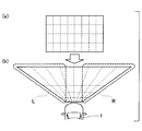
- FIG. 3A shows a plurality of round marks drawn in a lattice pattern at equal intervals on the ground in front of the vehicle 1 as viewed from above the vehicle 1.
- two alternate long and short dash lines extending obliquely from the in-vehicle camera 10F represent the boundary between the imaging region and the blind spot region of the in-vehicle camera 10F.
- a round mark displayed with a thick solid line indicates that the mark is within the imaging region of the in-vehicle camera 10F
- a round mark displayed with a thin broken line indicates that the mark is mounted on the vehicle. It represents that it is in the blind spot area of the camera 10F.
- the in-vehicle camera 10F (or the in-vehicle camera 10R) images such a ground from obliquely above.
- FIG. 3B shows a captured image obtained by the in-vehicle camera 10F.
- the photographed image shows a mark on the ground that exists within the photographing range of the in-vehicle camera 10F.
- the mark a on the photographed image is the mark A on the ground in FIG. 3A
- the mark b on the photographed image is the mark B on the ground.
- the mark c and the mark d on the photographed image are the marks C and D on the ground.
- the captured image shown in FIG. 4A is converted into an overhead image as shown in FIG.
- the bird's-eye view image thus obtained becomes an image that spreads in the left-right direction as the position is further away. This is because the imaging range of the in-vehicle camera 10F (or in-vehicle camera 10R) is widened on both the left and right sides (see FIG. 3A).
- FIG. 4B a region that extends to the left in the overhead image is displayed as region L, and a region that extends to the right is displayed as region R.
- both the region L and the region R are in the imaging region of the in-vehicle camera 10F.
- the region L becomes a blind spot region in the left direction of the vehicle 1
- the region R becomes a blind spot region in the right direction of the vehicle 1.
- a bird's-eye view image (shooting bird's-eye view image) obtained by line-of-sight conversion of the photographed image of the in-vehicle camera 10F is stored, and the current blind spot area is selected from the past photographed bird's-eye images as the vehicle 1 moves.
- the image (history image) of the part corresponding to is cut out and displayed. In this way, it is possible to display a bird's-eye view image also in the left and right area of the vehicle 1.
- the above is the basic concept of displaying a bird's-eye view image of the left and right region of the vehicle 1 using the history image.
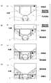
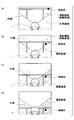
- FIG. 5 shows a state in which the bird's-eye view around the vehicle 1 displayed on the display screen 11 changes as the vehicle 1 moves forward.
- the front portion of the vehicle 1 is enlarged and displayed.
- two white lines are drawn on the ground in front of the vehicle 1 in parallel to the traveling direction of the vehicle 1, and one line is perpendicular to the traveling direction of the vehicle 1 on the back side.
- the white line is drawn. Further, here, it is assumed that a photographed bird's-eye view image generated by line-of-sight conversion in the past has not yet been stored.
- FIG. 5A shows an overhead view image around the vehicle 1 displayed on the display screen 11 first.
- a shooting overhead image generated by line-of-sight conversion of a captured image of the in-vehicle camera 10 ⁇ / b> F is displayed in the imaging area in front of the vehicle 1.
- a moving object is shown on the white line.
- no history image is displayed in the left and right blind spot areas of the vehicle 1.
- FIG. 5B shows an overhead view image around the vehicle 1 displayed on the display screen 11 with the vehicle 1 slightly advanced.
- the position of the white line is slightly closer to the vehicle 1 as the vehicle 1 slightly moves forward.
- the moving body that was on the white line has moved to the near side of the white line.
- the captured bird's-eye view image is an image obtained by line-of-sight conversion of the current image photographed by the in-vehicle camera 10F
- the fact that the moving body is in front of the white line in the photographed bird's-eye view image is also the photographed image of the in-vehicle camera 10F. It can be considered that the moving body is in front of the white line. Therefore, on the display screen 11 shown in FIG. 5B, it can be considered that the position where the moving object actually exists is correctly displayed.
- the left and right blind spot areas of the vehicle 1 are images (corresponding to images) of the corresponding part from the past photographing bird's-eye images displayed in FIG. Image) is cut out and displayed.
- the history image is displayed with diagonal lines in order to distinguish the captured overhead image from the history image.
- FIG. 5C shows a bird's-eye view of the surroundings of the vehicle 1 displayed on the display screen 11 in a state where the vehicle 1 has further advanced a little.
- a white line ahead of the vehicle 1 is displayed at a position closer to the vehicle 1.
- the white line in the imaging area in front of the vehicle 1 is a slight part, and most of the white line exists in the left and right blind spot areas of the vehicle 1.
- the blind spot area since a history image obtained by cutting out the corresponding portion from the past shooting overhead image displayed in FIG. 5A or 5B is displayed, You can confirm the position of the white line with.
- the moving object is also displayed on the display screen 11 shown in FIG.
- the position of the moving body shown in FIG. 5C is not changed from the position of the moving body shown in FIG. This is because the moving body image in FIG. 5C is a history image cut out from the image displayed in the photographic overhead image in FIG. 5B, and the image in FIG. 5C is displayed. It is because it is a past image from the point of view.
- the moving body is actually moving further from the time when the image of FIG. 5B is displayed. If the moving direction and moving speed of the moving body do not change, the moving body at the time when the image of FIG. 5C is displayed should be present at the position of the white circle indicated by the broken line in the figure. . That is, in this case, the driver misunderstands that the position of the moving body is farther than the actual position.
- FIG. 5D shows a bird's-eye view image around the vehicle 1 displayed on the display screen 11 in a state where the vehicle 1 has advanced a little further from the state shown in FIG. 5C.
- the entire white line is displayed as a history image.
- a moving object is also displayed in the image of FIG. 5D, but since this moving object is displayed as a history image, the position of the moving object with respect to the white line is displayed in the image of FIG. 5B. It has not changed from where it was. However, if the moving direction and moving speed of the moving body do not change, the moving body should actually exist at the position of the white circle indicated by the broken line in the figure.
- the moving direction and moving speed of the moving body are not always constant. Therefore, it is difficult to estimate the actual position of the moving body.
- the image display device 100 of the present embodiment has the following: Execute image display processing.
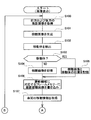
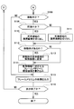
- Image display processing of this embodiment 6 and 7 show flowcharts of image display processing executed by the image display apparatus 100 of the present embodiment.
- each section is expressed as S100, for example.
- each section can be divided into a plurality of subsections, while a plurality of sections can be combined into one section.
- each section can be referred to as a device, module, or means.
- each of the above sections or a combination thereof includes not only (i) a section of software combined with a hardware unit (eg, a computer), but also (ii) hardware (eg, an integrated circuit, As a section of (wiring logic circuit), it can be realized with or without the function of related devices.
- the hardware section can be included inside the microcomputer.
- the image display process when the image display process is started, first, captured images of the front and rear of the vehicle 1 are acquired from the in-vehicle camera 10F and the in-vehicle camera 10R (S100). Then, the captured images acquired from the in-vehicle cameras 10F and 10R are line-of-sight-converted to generate shooting overhead images for the shooting areas in front and rear of the vehicle 1 (S101).
- a moving body is detected from the overhead images taken from the front and rear of the vehicle 1 (S102). Any known method may be used to detect the moving object. And it is judged whether the mobile body was detected (S103). As a result, when the moving object is not detected (S103: NO), the front and rear shooting overhead images are stored in the memory in a state where the shooting timing can be identified (for example, together with the time stamp) (S104). . On the other hand, when the moving body is detected (S103: YES), the photographing overhead image and the position of the moving body in the photographing overhead image are stored in the memory in a state where the photographing timing can be identified ( S105).
- the position of the shooting bird's-eye image and the moving object is determined for the front shooting bird's-eye image. It memorize
- the frame memory is a memory area used for displaying an image on the display screen 11.
- An image displayed on the display screen 11 is generated on the frame memory.
- the image is displayed on the display screen 11 by outputting the data in the frame memory as a video signal.
- Each address on the frame memory corresponds to each pixel on the display screen 11.
- the front bird's-eye view image is written in each address of the frame memory corresponding to the shooting area of the in-vehicle camera 10F on the display screen 11, and the rear address is written in each address of the frame memory corresponding to the shooting area of the in-vehicle camera 10R.
- the image display device 100 acquires movement information (also referred to as movement data) of the vehicle 1 (S107).
- the movement information of the vehicle 1 is information (or data) acquired from the steering angle sensor 12, the vehicle speed sensor 13, the shift position sensor 14, or the like.
- the display mode of the moving object in the history image is changed to a special mode different from the normal mode (S113).
- the color of the moving object in the history image is changed (for example, changed to red) and displayed, the moving object is displayed surrounded by a red frame or a white frame, and the moving object image is displayed in advance. It replaces the stored graphic image and displays it.
- the operation for changing the display mode of the moving object is not performed.
- the history image obtained in this way is written in the frame memory corresponding to the blind spot area of the in-vehicle camera 10F and the in-vehicle camera 10R on the display screen 11 (S114).
- the history image changed to the special mode is written.
- the image displayed on the display screen 11 is displayed on the frame memory by writing the history image. Complete.
- the image display device 100 outputs the image on the frame memory to the display screen 11 (S115). As a result, a bird's-eye view image as if the periphery of the vehicle 1 was viewed from above is displayed on the display screen 11.
- the series of processing for writing the history image (S109 to S114) is not performed, and the image on the frame memory is output to the display screen 11. (S115).
- the display screen 11 displays an image in which only the captured bird's-eye images displayed before and after the vehicle 1 are updated.
- the history image is displayed in the blind spot area on the display screen 11.
- the history image remaining on the frame memory is displayed in the blind spot area of the display screen 11 for a predetermined time after the vehicle 1 is stopped, but after the predetermined time has elapsed, the history image on the frame memory is displayed. May be deleted so that the history image is not displayed on the display screen 11.
- FIG. 8 illustrates a bird's-eye view image displayed on the display screen 11 by the image display process of the present embodiment described above.
- FIG. 8 illustrates a bird's-eye view image displayed on the display screen 11 by the image display process of the present embodiment described above.
- two white lines parallel to the traveling direction of the vehicle 1 and right angles to the two white lines are present on the ground in front of the vehicle 1. It is assumed that a single white line is drawn. Further, it is assumed that the moving body is moving in the same manner as in the case shown in FIG. In FIG. 5, the history image is displayed with a diagonal line, but in FIG. 8, the history image is displayed without a diagonal line in order to avoid complexity.
- the moving body when the moving body enters the blind spot area and is displayed as a history image, in this embodiment, the moving body is displayed in a mode different from the normal mode.
- the moving body is displayed in a color different from normal, such as red or yellow. For this reason, the driver thinks what happened and confirms the surroundings of the vehicle 1 by looking directly at the moving body, not through the display screen 11, so that the correct position of the moving body is recognized. Can do.
- the moving body is displayed on the display screen 11 in a mode different from the normal mode.
- the driver tries to visually confirm the moving body, and as a result, the correct position of the moving body is obtained. Recognize For this reason, even if the moving body is not displayed at the correct position on the display screen 11, it is possible to prevent the driver from misunderstanding the position of the moving body.
- FIG. 9 shows a modification in which a history image is displayed in such a mode.
- the moving body is present in the captured bird's-eye view image, and is not present in the left-right history image of the vehicle 1. For this reason, any history image in the left-right direction is displayed in the same mode as in the normal mode, similar to the captured bird's-eye view image.
- the history image on the right side of the vehicle 1 is displayed in a mode different from the normal mode, for example, a reddish color or a yellowish color.
- the left side history image of the vehicle 1 is displayed in the same mode as usual.
- the history image on the right side of the vehicle 1 is displayed on the display screen 11 in a mode different from the normal mode, so it is thought that what has happened, and the region on the right side of the vehicle 1 is directly checked by visual observation. . As a result, it is possible to recognize the correct position of the moving body.
- the history image on the side where the moving body is present with respect to the vehicle 1 is displayed in a mode different from the normal mode. Therefore, for example, as shown in FIGS. 9B to 9D, when there is a portion where no history image is displayed in the blind spot area on the side of the vehicle 1, only the portion of the history image is normally displayed. Is displayed in a different mode.
- the entire blind spot area on the side where the moving object exists may be displayed in a mode different from the normal mode.
- the history image on the side where the moving body exists is displayed in a mode different from the normal mode, and the mobile body itself is displayed in a mode different from the normal mode.
Abstract
A display apparatus for displaying a vehicle periphery image line-of-vision-converts a captured image of a vehicle-mounted camera to generate a captured-from-above image, and stores the generated captured-from-above image. If any movable body exists in the captured-from-above image, the display apparatus also stores the position of the movable body in the captured-from-above image. The display apparatus acquires vehicle movement information, cuts, out of the stored captured-from-above image, a part thereof that is a history image obtained by capturing the image of a vehicle blind spot area, and displays, on a display screen, the history image together with the captured-from-above image. At this moment, if the movable body exists in the history image, then the display apparatus displays the movable body in a different display mode from the display mode in the case where the movable body exists in the captured-from-above image.
Description
本開示は、2014年2月12日に出願された日本出願番号2014-24013号に基づくもので、ここにその記載内容を援用する。
This disclosure is based on Japanese Patent Application No. 2014-24013 filed on February 12, 2014, the contents of which are incorporated herein.
本開示は、車載カメラを用いて車両の周辺領域を撮影した画像を、表示画面上に表示する表示装置(Display Apparatus)および表示方法(Display Method)に関する。
This disclosure relates to a display device (Display Apparatus) and a display method (Display Method) for displaying an image obtained by photographing a peripheral region of a vehicle using an in-vehicle camera on a display screen.
車両の前後左右に搭載した車載カメラで得られた撮影画像に対して、あたかも車両を上方から見たような画像に視線変換する処理を施して、得られた画像(俯瞰画像)を表示する装置が知られている。車両の運転者は俯瞰画像で確認することができれば、周囲に存在する障害物と装置を搭載するホスト車両との位置関係や、路面に描かれた表示などとホスト車両との位置関係を、距離感も含めて容易に把握することが可能となる。
An apparatus for displaying captured images obtained by vehicle-mounted cameras mounted on the front, rear, left, and right sides of the vehicle, by converting the line of sight into an image as if the vehicle was viewed from above, and displaying the obtained image (overhead image) It has been known. If the driver of the vehicle can confirm the bird's-eye view image, the positional relationship between the obstacle present in the surroundings and the host vehicle on which the device is mounted, the positional relationship between the display drawn on the road surface and the host vehicle, etc. It is possible to easily grasp the feeling.
また、車両の左右には車載カメラを搭載しないにも拘わらず、車両の前後左右方向の周辺領域の俯瞰画像を表示する技術も提案されている(特許文献1)。この技術では、車両の左右方向の周辺領域については車載カメラで直接画像を撮影することはできないが、車両の前後に搭載した車載カメラの画像から、次のような原理で左右方向の俯瞰画像を生成する。
In addition, a technique for displaying an overhead image of a peripheral region in the front-rear and left-right directions of the vehicle has been proposed (Patent Document 1) even though the vehicle-mounted cameras are not mounted on the left and right sides of the vehicle. With this technology, it is not possible to directly capture images in the left and right peripheral areas of the vehicle with the in-vehicle camera, but from the images of the in-vehicle cameras mounted on the front and rear of the vehicle, the overhead view image in the left and right direction is obtained according to the following principle. Generate.
先ず、車両の前方の車載カメラによって得られた撮影画像には、車両の正面の領域だけでなく、その両側には斜め前方の領域も写っている。従って、前方の車載カメラから得られる俯瞰画像にも、車両の左右斜め前方の領域の画像が含まれている。そして、この斜め前方の領域は、車両が前進することによって、やがては車両の左右方向の領域となる。このことから、俯瞰画像中に含まれる車両の斜め前方の領域の画像を記憶しておけば、車両が前進した後は、車両の左右方向の俯瞰画像として用いることができる。
First, in the captured image obtained by the in-vehicle camera in front of the vehicle, not only the area in front of the vehicle but also the diagonally forward areas are shown on both sides. Therefore, the bird's-eye view image obtained from the front vehicle-mounted camera also includes an image of a region diagonally forward in the left and right directions of the vehicle. This diagonally forward area eventually becomes an area in the left-right direction of the vehicle as the vehicle moves forward. Therefore, if an image of a region diagonally forward of the vehicle included in the overhead image is stored, it can be used as an overhead image in the left-right direction of the vehicle after the vehicle has advanced.
車両が更に前進した場合には、その前進よりも前に記憶しておいた俯瞰画像の中から、該当する部分の画像を切り出して用いればよい。こうすれば、車両の左右には車載カメラを搭載しなくても、車両の前後左右方向の周辺領域の俯瞰画像を表示することができる。
When the vehicle further moves forward, the image of the corresponding part may be cut out and used from the overhead view image stored before the forward movement. In this way, it is possible to display a bird's-eye view of the surrounding area in the front-rear and left-right directions of the vehicle without mounting on-vehicle cameras on the left and right sides of the vehicle.
尚、車両の左右方向に表示される俯瞰画像は、実際には少し前に撮影されていた過去の俯瞰画像である。このことから、過去の俯瞰画像から切り出されて車両の左右方向に表示される画像は「履歴画像」と呼ばれる。
Note that the bird's-eye view image displayed in the left-right direction of the vehicle is a past bird's-eye view image that was actually taken a little while ago. Therefore, an image cut out from a past bird's-eye view image and displayed in the left-right direction of the vehicle is called a “history image”.
また、車両が後進している場合には、車両の後方の車載カメラによる俯瞰画像を記憶しておき、俯瞰画像の中から切り出した履歴画像を車両の左右方向部分に表示してやればよい。こうすれば、後進時にも車両の前後左右方向の俯瞰画像を表示することができる。
Further, when the vehicle is moving backward, it is only necessary to store a bird's-eye view image by an in-vehicle camera behind the vehicle and display a history image cut out from the bird's-eye view image in the left and right direction portion of the vehicle. By so doing, it is possible to display a bird's-eye view image in the front-rear and left-right directions of the vehicle even when the vehicle is traveling backward.
しかし、上述したように、車載カメラの死角となる領域を含めて俯瞰画像を表示するために履歴画像を利用する技術には、表示する領域内に移動体が存在する場合に、運転者に誤解を与える可能性がある。
However, as described above, in the technology that uses a history image to display a bird's-eye view image including an area that is a blind spot of an in-vehicle camera, the driver misunderstands when a moving object exists in the display area. May give.
これは次のような理由による。先ず、移動体が車載カメラの撮影範囲内にいる場合は、車載カメラの画像を視線変換して俯瞰画像を表示することで、ホスト車両と移動体との位置関係や、位置関係が変化していく様子を正しく表示することができる。 その後、車両が移動したことに伴って移動体が車載カメラの死角に入ると、車載カメラの画像を視線変換した俯瞰画像では移動体を表示することができなくなるので、履歴画像を用いて表示する必要が生じる。ところが、履歴画像は少し前に撮影された画像なので、移動体の正しい位置を表示しているとは限らない。また、履歴画像を用いて表示された移動体の位置は、車両の進行に伴って、車両の進行方向とは反対側に少しずつ移動していくが、車両が移動した分だけ反対方向に移動するだけなので、あたかも移動体が地面に対しては止まっているかのように見えてしまう。このため、実際には移動体が車両の直ぐ近くまで接近していたとしても、移動体が止まっているので車両に接触しないと、運転者に誤解させてしまう可能性がある。
This is due to the following reasons. First, when the moving body is within the shooting range of the on-vehicle camera, the positional relationship between the host vehicle and the moving body and the positional relationship change by changing the line of sight of the image of the on-vehicle camera and displaying the overhead image. It is possible to correctly display the state of going. After that, when the moving body enters the blind spot of the in-vehicle camera as the vehicle moves, the overhead image obtained by converting the line of sight of the in-vehicle camera cannot display the moving body. Need arises. However, since the history image is an image taken a while ago, the correct position of the moving body is not always displayed. In addition, the position of the moving object displayed using the history image gradually moves in the opposite direction to the traveling direction of the vehicle as the vehicle progresses, but moves in the opposite direction by the amount of movement of the vehicle. Because it only does, it will appear as if the moving body has stopped against the ground. For this reason, even if the moving body is approaching to the immediate vicinity of the vehicle, the moving body is stopped, so that it may be misunderstood by the driver unless it contacts the vehicle.
この開示は、従来技術が有する上述した課題に鑑みてなされたものであり、車両の周辺に移動体が存在する場合でも、運転者に誤解を与えることなく、履歴画像を用いて車両周辺の俯瞰画像を表示することが可能な技術の提供を目的とする。
This disclosure has been made in view of the above-described problems of the prior art, and even when a moving body exists around the vehicle, an overview of the surroundings of the vehicle using a history image without misleading the driver. An object is to provide a technique capable of displaying an image.
上述した課題を解決するために本開示の一つの例によれば、車両周辺画像表示装置および車両周辺画像表示方法は、次のように提供される。車載カメラによって得られた撮影画像を視線変換することによって撮影俯瞰画像を生成し、得られた撮影俯瞰画像を記憶する。また、撮影俯瞰画像に移動体が存在する場合には撮影俯瞰画像中での移動体の位置も記憶しておく。そして、車両の移動量に関する移動情報を取得して、記憶しておいた撮影俯瞰画像の中から、車両の死角領域を撮影した部分の画像である履歴画像を切り出して、撮影俯瞰画像と共に表示画面上に表示する。この時、履歴画像中に移動体が存在する場合には、その移動体が撮影俯瞰画像中に存在していた場合とは異なる表示モードで移動体を表示する。
In order to solve the above-described problem, according to one example of the present disclosure, a vehicle peripheral image display device and a vehicle peripheral image display method are provided as follows. A photographic overhead view image is generated by performing line-of-sight conversion on a captured image obtained by the in-vehicle camera, and the obtained photographic overhead view image is stored. Further, when a moving body is present in the photographic overhead image, the position of the moving body in the photographic overhead image is also stored. Then, movement information relating to the amount of movement of the vehicle is acquired, and a history image, which is an image of a portion where the blind spot area of the vehicle is photographed, is cut out from the stored photographing bird's-eye view image and displayed together with the photographing bird's-eye view image Display above. At this time, if a moving object exists in the history image, the moving object is displayed in a display mode different from that in the case where the moving object exists in the captured overhead image.
こうすれば、表示画面上での移動体の表示モードが変わるので、移動体が履歴画像によって表示されていることを運転者に認識させることができる。その結果、運転者は、例えば直接目視するなどして移動体を確認しようとするので、移動体の位置の誤解を回避することが可能となる。
In this way, since the display mode of the moving body on the display screen is changed, the driver can recognize that the moving body is displayed by the history image. As a result, the driver tries to confirm the moving body by, for example, direct visual observation, so that misunderstanding of the position of the moving body can be avoided.
本開示についての上記目的およびその他の目的、特徴や利点は、添付の図面を参照しながら下記の詳細な記述により、より明確になる。
本開示の実施形態の画像表示装置を搭載した車両を示す説明図、
画像表示装置の大まかな内部構成を示す説明図、
車両の前方の領域を撮影して得られる撮影画像を示した説明図、
撮影画像を俯瞰画像に変換する原理についての説明図、
車両の周辺に移動体が存在していると運転者に誤解を与える可能性がある理由についての比較説明図、
本実施形態の画像表示処理の前半部分のフローチャート図、
本実施形態の画像表示処理の後半部分のフローチャート図、
本実施形態の画像表示装置によって得られる履歴画像を例示した説明図、
本実施形態の画像表示装置によって得られる履歴画像の他の態様を例示した説明図。
The above and other objects, features and advantages of the present disclosure will become more apparent from the following detailed description with reference to the accompanying drawings.
Explanatory drawing which shows the vehicle carrying the image display apparatus of embodiment of this indication, An explanatory view showing a rough internal configuration of the image display device, Explanatory drawing which showed the picked-up image obtained by image | photographing the area | region ahead of a vehicle, Explanatory drawing about the principle of converting a shot image into a bird's-eye view image, Comparison explanatory diagram about the reason why there is a possibility of misleading the driver when there is a moving body around the vehicle, The flowchart figure of the first half part of the image display process of this embodiment, The flowchart figure of the latter half part of the image display process of this embodiment, Explanatory drawing which illustrated the history image obtained by the image display device of this embodiment, Explanatory drawing which illustrated the other aspect of the log | history image obtained by the image display apparatus of this embodiment.
以下では、上述した本開示の内容を明確にするために本開示の実施形態について説明する。
Hereinafter, embodiments of the present disclosure will be described in order to clarify the contents of the present disclosure described above.
A.装置構成 :
図1には、画像表示装置100を搭載した車両1(ホスト車両とも言及される)が示されている。尚、本実施形態では、画像表示装置100は、車両周辺画像表示装置とも言及される。 A. Device configuration :
FIG. 1 shows a vehicle 1 (also referred to as a host vehicle) equipped with animage display device 100. In the present embodiment, the image display device 100 is also referred to as a vehicle periphery image display device.
図1には、画像表示装置100を搭載した車両1(ホスト車両とも言及される)が示されている。尚、本実施形態では、画像表示装置100は、車両周辺画像表示装置とも言及される。 A. Device configuration :
FIG. 1 shows a vehicle 1 (also referred to as a host vehicle) equipped with an
図示されるように車両1は、車両1の前方に搭載された車載カメラ10Fと、車両1の後方に搭載された車載カメラ10Rと、車室内に搭載された表示画面11と、画像表示装置100などを備えている。尚、本実施形態では、車両1の前方および後方にそれぞれ車載カメラ10F,10Rが搭載されているものとして説明するが、車載カメラ10Fあるいは車載カメラ10Rの何れか一方を搭載した車両1に対しても、本開示を適用することができる。
As illustrated, the vehicle 1 includes an in-vehicle camera 10F mounted in front of the vehicle 1, an in-vehicle camera 10R mounted in the rear of the vehicle 1, a display screen 11 mounted in the vehicle interior, and an image display device 100. Etc. In the present embodiment, the vehicle-mounted cameras 10F and 10R are described as being mounted on the front and rear of the vehicle 1, respectively. However, the vehicle 1 mounted with either the vehicle-mounted camera 10F or the vehicle-mounted camera 10R is described. Also, the present disclosure can be applied.
画像表示装置100は、車載カメラ10F,10Rで撮影した車両1の周辺の画像を受け取ると、その画像を、車両1の上方から撮影したような俯瞰画像に変換した後、得られた画像を表示画面11に表示する。
When the image display device 100 receives an image of the periphery of the vehicle 1 taken by the in- vehicle cameras 10F and 10R, the image display device 100 converts the image into an overhead view image taken from above the vehicle 1, and then displays the obtained image. It is displayed on the screen 11.
また、車両1には、操舵ハンドル2の操舵角を検出する操舵角センサー12や、車速を検出する車速センサー13や、図示しない変速機のシフトポジションを検出するシフト位置センサー14などが搭載されている。操舵角センサー12や、車速センサー13、シフト位置センサー14の出力は画像表示装置100に入力されており、画像表示装置100は、これらの出力に基づいて車両1の移動量(移動速度および移動方向)に関する移動情報を取得する。
The vehicle 1 is also equipped with a steering angle sensor 12 for detecting the steering angle of the steering handle 2, a vehicle speed sensor 13 for detecting the vehicle speed, a shift position sensor 14 for detecting a shift position of a transmission (not shown), and the like. Yes. The outputs of the steering angle sensor 12, the vehicle speed sensor 13, and the shift position sensor 14 are input to the image display device 100, and the image display device 100 determines the movement amount (movement speed and movement direction) of the vehicle 1 based on these outputs. ) Related movement information.
そして、画像表示装置100は、車両1の移動情報と、車載カメラ10F,10Rによって得られた俯瞰画像とに基づいて、車載カメラ10F,10Rの死角になっている領域(車両1の左右方向の領域)についての俯瞰画像を生成して、表示画面11に表示する。
And the image display apparatus 100 is based on the movement information of the vehicle 1 and the bird's-eye view images obtained by the in- vehicle cameras 10F and 10R. A bird's-eye view image for (region) is generated and displayed on the display screen 11.
図2には、本実施形態の画像表示装置100の大まかな内部構成が示されている。図示されるように本実施形態の画像表示装置100は、撮影画像取得部101と、撮影俯瞰画像生成部102と、移動体検出部103と、撮影俯瞰画像記憶部104と、移動情報取得部105と、表示画像生成部106とを備えている。
FIG. 2 shows a rough internal configuration of the image display apparatus 100 of the present embodiment. As shown in the figure, the image display apparatus 100 of the present embodiment includes a captured image acquisition unit 101, a captured overhead image generation unit 102, a moving body detection unit 103, a captured overhead image storage unit 104, and a movement information acquisition unit 105. And a display image generation unit 106.
尚、これら6つの「部(セクション)」は、画像表示装置100が車両1の周辺の画像を表示画面11に表示する機能に着目して、画像表示装置100の内部を便宜的に分類した抽象的な概念であり、画像表示装置100が物理的に6つの部分に区分されることを表すものではない。従って、これらの「部」は、CPUで実行されるコンピュータープログラムとしてソフトウエアの構成要素として実現することもできるし、LSIやメモリーを含む電子回路としてハードウエアの構成要素として実現することもできるし、更にはこれらを組合せることによって実現することもできる。
Note that these six “sections” are abstractions in which the interior of the image display apparatus 100 is classified for convenience, focusing on the function of the image display apparatus 100 displaying an image around the vehicle 1 on the display screen 11. This does not represent that the image display device 100 is physically divided into six parts. Therefore, these “units” can be realized as software components as computer programs executed by the CPU, or can be realized as hardware components as electronic circuits including LSIs and memories. Further, it can be realized by combining these.
撮影画像取得部101は、車載カメラ10Fおよび車載カメラ10Rに接続されており、車載カメラ10Fから車両1の前方の領域を斜め上方から撮影した撮影画像を一定周期(約30Hz)で取得する。また、車載カメラ10Rからは、車両1の後方の領域を斜め上方から撮影した撮影画像を一定周期(約30Hz)で取得する。
The captured image acquisition unit 101 is connected to the in-vehicle camera 10F and the in-vehicle camera 10R, and acquires a captured image obtained by capturing an area in front of the vehicle 1 from obliquely above from the in-vehicle camera 10F at a constant cycle (about 30 Hz). In addition, from the in-vehicle camera 10 </ b> R, a captured image obtained by capturing an area behind the vehicle 1 from obliquely above is acquired at a constant period (about 30 Hz).
撮影俯瞰画像生成部102は、撮影画像取得部101から車載カメラ10F,10Rによる撮影画像を受け取って俯瞰画像を生成する。すなわち、車載カメラ10Fによって得られる撮影画像は、車両1の前方の領域を斜め上方から撮影した画像であるが、この画像に対して後述する視線変換を施すことにより、車両1の上方から撮影したような俯瞰画像を生成する。同様に、車載カメラ10Rによる撮影画像は、車両1の後方の領域を斜め上方から撮影した画像であるが、この画像を、車両1の上方から撮影したような俯瞰画像に変換する。車載カメラ10F,10Rによる撮影画像に視線変換を施して俯瞰画像を生成する方法については後述する。本実施形態では、撮影俯瞰画像生成部102は、撮影俯瞰画像生成デバイス/ミーンズとも言及される。
The photographed bird's-eye view image generation unit 102 receives the images taken by the in- vehicle cameras 10F and 10R from the photographed image acquisition unit 101 and generates an overhead image. That is, the photographed image obtained by the in-vehicle camera 10F is an image obtained by photographing an area in front of the vehicle 1 from obliquely above, and the photographed image is obtained from above the vehicle 1 by performing line-of-sight conversion described later on this image. Such a bird's-eye view image is generated. Similarly, the image captured by the in-vehicle camera 10 </ b> R is an image obtained by capturing an area behind the vehicle 1 from obliquely above, and this image is converted into an overhead view image captured from above the vehicle 1. A method for generating a bird's-eye view image by performing line-of-sight conversion on images captured by the in- vehicle cameras 10F and 10R will be described later. In the present embodiment, the photographing overhead image generation unit 102 is also referred to as a photographing overhead image generation device / means.
尚、後述するように、本実施形態の画像表示装置100では、車両1の前後方向の領域だけでなく、車両1の左右方向の領域についても俯瞰画像を生成して、表示画面11に表示することができる。ここで、車両1の前後方向に表示する俯瞰画像は、車載カメラ10F,10Rで撮影した現在の画像を視線変換した画像である。これに対し、車両1の左右方向に表示する俯瞰画像は、車両1の移動情報に基づいて、車両1の前後方向に表示した過去の俯瞰画像から合成した画像である。
As will be described later, in the image display device 100 according to the present embodiment, an overhead image is generated not only in the front-rear direction area of the vehicle 1 but also in the left-right direction area of the vehicle 1 and displayed on the display screen 11. be able to. Here, the bird's-eye view image displayed in the front-rear direction of the vehicle 1 is an image obtained by line-of-sight conversion of the current image captured by the in- vehicle cameras 10F and 10R. On the other hand, the bird's-eye view image displayed in the left-right direction of the vehicle 1 is an image synthesized from the past bird's-eye view images displayed in the front-rear direction of the vehicle 1 based on the movement information of the vehicle 1.
そこで以下では、車両1の前後方向に表示する俯瞰画像を、車両1の左右方向に表示する合成された俯瞰画像と区別するために「撮影俯瞰画像」と称することにする。また、単に「俯瞰画像」という時は、車両1の上方から見た画像を意味しており、従って、撮影俯瞰画像も履歴画像も「俯瞰画像」に該当する。撮影俯瞰画像生成部102は、生成した撮影俯瞰画像を、移動体検出部103と、撮影俯瞰画像記憶部104と、表示画像生成部106とに出力する。
Therefore, hereinafter, the bird's-eye view image displayed in the front-rear direction of the vehicle 1 is referred to as a “shooting bird's-eye view image” in order to distinguish it from the synthesized bird's-eye view image displayed in the left-right direction of the vehicle 1. The term “overhead image” simply refers to an image viewed from above the vehicle 1, and accordingly, both the imaged bird's-eye view image and the history image correspond to the “overhead image”. The shooting bird's-eye view image generation unit 102 outputs the generated shooting bird's-eye view image to the moving object detection unit 103, the shooting bird's-eye view image storage unit 104, and the display image generation unit 106.
移動体検出部103は、撮影俯瞰画像生成部102から供給された撮影俯瞰画像を解析して、撮影俯瞰画像中の移動体を検出する。移動体は、過去に受け取った画像と、新たに受け取った画像とを比較することによって検出することができる。
The moving body detection unit 103 analyzes the shooting overhead image supplied from the shooting overhead image generation unit 102 and detects a moving body in the shooting overhead image. The moving object can be detected by comparing an image received in the past with a newly received image.
尚、本実施形態では、移動体検出部103は、撮影俯瞰画像から移動体を検出するものとして説明するが、図中で破線の矢印で示すように、撮影画像取得部101から車載カメラ10F,10Rによる撮影画像を受け取って、撮影画像中の移動体を検出しても良い。移動体検出部103は、移動体検出デバイス/ミーンズとも言及される。
In the present embodiment, the moving body detection unit 103 is described as detecting a moving body from the captured bird's-eye view image. However, as indicated by the dashed arrows in the drawing, the captured image acquisition unit 101 receives the in-vehicle camera 10F, A moving image in the captured image may be detected by receiving a captured image by 10R. The moving body detection unit 103 is also referred to as a moving body detection device / means.
撮影俯瞰画像記憶部104は、撮影俯瞰画像生成部102から供給された撮影俯瞰画像を記憶する。また、その撮影俯瞰画像中で移動体検出部103によって移動体が検出された場合には、撮影俯瞰画像中で移動体が検出された位置も、撮影俯瞰画像に対応付けて記憶する。本実施形態では、撮影俯瞰画像記憶部104は、撮影俯瞰画像記憶デバイス/ミーンズとも言及される。
The photographic overhead image storage unit 104 stores the photographic overhead image supplied from the photographic overhead image generation unit 102. Further, when a moving body is detected by the moving body detection unit 103 in the captured bird's-eye view image, the position where the moving body is detected in the captured bird's-eye view image is also stored in association with the captured bird's-eye view image. In the present embodiment, the photographing overhead image storage unit 104 is also referred to as a photographing overhead image storage device / means.
尚、移動体検出部103が、撮影俯瞰画像ではなく、その撮影俯瞰画像が視線変換される前の画像(車載カメラ10F,10Rによる撮影画像)を用いて移動体を検出する場合は、撮影画像中で検出された移動体の位置に対して視線変換を施すことによって、撮影俯瞰画像中での移動体の位置を求めることができる。
Note that when the moving body detection unit 103 detects a moving body using an image (photographed images by the in- vehicle cameras 10F and 10R) before the line-of-sight of the captured overhead image is not a captured overhead image, the captured image is captured. By performing line-of-sight conversion on the position of the moving body detected in the position, the position of the moving body in the captured bird's-eye view image can be obtained.
移動情報取得部105は、操舵角センサー12や、車速センサー13や、シフト位置センサー14に接続されている。移動情報取得部105は、これらセンサーの出力に基づいて、車両1の移動情報を取得する。ここで、車両1の移動情報とは、車両1が前進しているのか、後進しているのか、停車しているのかといった情報や、車両1が真っ直ぐ進んでいるのか、右旋回しているのか、左旋回しているのか、旋回している場合には旋回の大きさに関する情報や、車両1の移動速度に関する情報などである。移動情報取得部105は、取得した車両1の移動情報を表示画像生成部106に出力する。移動情報取得部105は、移動情報取得デバイス/ミーンズとも言及される。
The movement information acquisition unit 105 is connected to the steering angle sensor 12, the vehicle speed sensor 13, and the shift position sensor 14. The movement information acquisition unit 105 acquires movement information of the vehicle 1 based on the outputs of these sensors. Here, the movement information of the vehicle 1 is information such as whether the vehicle 1 is moving forward, backward, or stopped, whether the vehicle 1 is moving straight, or whether it is turning right Whether the vehicle is turning left, or if it is turning, information on the magnitude of the turn, information on the moving speed of the vehicle 1, and the like. The movement information acquisition unit 105 outputs the acquired movement information of the vehicle 1 to the display image generation unit 106. The movement information acquisition unit 105 is also referred to as movement information acquisition device / means.
表示画像生成部106は、撮影俯瞰画像生成部102からの撮影俯瞰画像と、移動情報取得部105からの移動情報と、撮影俯瞰画像記憶部104に記憶されている過去の撮影俯瞰画像とを用いて、車両1の全周に亘る周辺領域についての俯瞰画像を生成して、表示画面11に表示する。
The display image generation unit 106 uses the shooting overhead image from the shooting overhead image generation unit 102, the movement information from the movement information acquisition unit 105, and the past shooting overhead image stored in the shooting overhead image storage unit 104. Thus, a bird's-eye view image of the peripheral region over the entire circumference of the vehicle 1 is generated and displayed on the display screen 11.
ここで、車両1の前方および後方の領域については、車載カメラ10F,10Rの撮影領域なので、車載カメラ10F,10Rによる撮影画像を視線変換した俯瞰画像(撮影俯瞰画像)を表示すればよい。しかし、車両1の右方向および左方向の領域については、車載カメラ10F,10Rの死角領域となるので、車載カメラ10F,10Rによる撮影画像を視線変換しただけでは俯瞰画像は得られない。そこで、撮影俯瞰画像記憶部104に記憶されている過去の撮影俯瞰画像の中から、車両1の移動情報に基づいて該当する部分の画像(履歴画像)を切り出すことによって、車両1の左右方向の領域についての俯瞰画像を生成する。本実施形態では、表示画像生成部106は、撮影俯瞰画像表示部/デバイス/ミーンズあるいは履歴画像表示部/デバイス/ミーンズとも言及される。
Here, the front and rear areas of the vehicle 1 are the imaging areas of the in- vehicle cameras 10F and 10R, and therefore, an overhead image (captured overhead image) obtained by line-of-sight conversion of the images captured by the in- vehicle cameras 10F and 10R may be displayed. However, since the areas in the right and left directions of the vehicle 1 are blind spots of the in- vehicle cameras 10F and 10R, a bird's-eye view image cannot be obtained simply by performing line-of-sight conversion on the images captured by the in- vehicle cameras 10F and 10R. Therefore, by cutting out an image (history image) of the corresponding part based on the movement information of the vehicle 1 from the past shooting bird's-eye images stored in the shooting bird's-eye image storage unit 104, An overhead image for the region is generated. In the present embodiment, the display image generation unit 106 is also referred to as a shooting overhead image display unit / device / means or a history image display unit / device / means.
以下では、車両1の左右方向の領域での俯瞰画像を生成する方法について説明するが、その準備として、先ず始めに、車載カメラ10F,10Rによる撮影画像を視線変換して撮影俯瞰画像を生成する方法について説明する。その後、かかる説明を踏まえて、車両1の左右方向の領域での俯瞰画像を生成する方法について説明する。
Hereinafter, a method for generating a bird's-eye view image in an area in the left-right direction of the vehicle 1 will be described. As a preparation for this, first, a photographed bird's-eye view image is generated by performing line-of-sight conversion on images taken by the in- vehicle cameras 10F and 10R. A method will be described. Then, based on this description, a method for generating a bird's-eye view image in an area in the left-right direction of the vehicle 1 will be described.
B.履歴画像を用いて車両の周辺の俯瞰画像を表示する原理 :
車両1の車載カメラ10F(あるいは車載カメラ10R)で撮影した地面に、複数の目印が等間隔で格子状に描かれていた場合について考える。 B. Principle of displaying a bird's-eye view of the surroundings of a vehicle using history images:
Consider a case where a plurality of landmarks are drawn in a grid pattern at equal intervals on the ground imaged by the in-vehicle camera 10F (or in-vehicle camera 10R) of the vehicle 1.
車両1の車載カメラ10F(あるいは車載カメラ10R)で撮影した地面に、複数の目印が等間隔で格子状に描かれていた場合について考える。 B. Principle of displaying a bird's-eye view of the surroundings of a vehicle using history images:
Consider a case where a plurality of landmarks are drawn in a grid pattern at equal intervals on the ground imaged by the in-
図3(a)には、車両1の前方の地面に等間隔で格子状に描かれた複数の丸い目印を、車両1の上方から見た状態で示されている。図中で、車載カメラ10Fから斜め方向に伸びる2本の一点鎖線は、車載カメラ10Fの撮影領域と死角領域との境界を表している。
FIG. 3A shows a plurality of round marks drawn in a lattice pattern at equal intervals on the ground in front of the vehicle 1 as viewed from above the vehicle 1. In the figure, two alternate long and short dash lines extending obliquely from the in-vehicle camera 10F represent the boundary between the imaging region and the blind spot region of the in-vehicle camera 10F.
また、丸い目印が太い実線で表示されているのは、その目印が車載カメラ10Fの撮影領域内にあることを表しており、丸い目印が細い破線で表示されているのは、その目印が車載カメラ10Fの死角領域内にあることを表している。車載カメラ10F(あるいは車載カメラ10R)は、このような地面を斜め上方から撮影する。
In addition, a round mark displayed with a thick solid line indicates that the mark is within the imaging region of the in-vehicle camera 10F, and a round mark displayed with a thin broken line indicates that the mark is mounted on the vehicle. It represents that it is in the blind spot area of the camera 10F. The in-vehicle camera 10F (or the in-vehicle camera 10R) images such a ground from obliquely above.
図3(b)には、車載カメラ10Fで得られる撮影画像が示されている。撮影画像には、車載カメラ10Fの撮影範囲内に存在する地面の目印が写っている。例えば、撮影画像上での目印aは、図3(a)の地面上の目印Aが写ったものであり、撮影画像上での目印bは、地面上の目印Bが写ったものである。同様に、撮影画像上での目印cおよび目印dは、地面上の目印Cおよび目印Dが写ったものである。
FIG. 3B shows a captured image obtained by the in-vehicle camera 10F. The photographed image shows a mark on the ground that exists within the photographing range of the in-vehicle camera 10F. For example, the mark a on the photographed image is the mark A on the ground in FIG. 3A, and the mark b on the photographed image is the mark B on the ground. Similarly, the mark c and the mark d on the photographed image are the marks C and D on the ground.
このように、車載カメラ10Fの撮影範囲内の地面上の座標と、撮影画像上の座標との間には1対1の対応関係が存在する。従って、この対応関係を利用すれば、図3(b)に例示した撮影画像を、図3(a)に例示したように車両1の上方から地面を見下ろしたような画像(俯瞰画像)に変換することができる。これが、車載カメラ10F(あるいは車載カメラ10R)の撮影画像を視線変換して俯瞰画像を生成する際の考え方である。
Thus, there is a one-to-one correspondence between the coordinates on the ground within the shooting range of the in-vehicle camera 10F and the coordinates on the shot image. Therefore, if this correspondence is used, the captured image illustrated in FIG. 3B is converted into an image (overhead image) in which the ground is looked down from above the vehicle 1 as illustrated in FIG. can do. This is the way of thinking when generating a bird's-eye view image by converting the line-of-sight of a captured image of the in-vehicle camera 10F (or in-vehicle camera 10R).
このような視線変換を行うことにより、図4(a)に示した撮影画像は、図4(b)に示すような俯瞰画像に変換される。こうして得られた俯瞰画像は、遠くの位置ほど左右方向に広がった画像となる。これは、車載カメラ10F(あるいは車載カメラ10R)の撮影範囲が左右両側に広がっていることによる(図3(a)参照)。図4(b)では、俯瞰画像中で左側に広がった領域を領域L、右側に広がった領域を領域Rと表示している。
By performing such line-of-sight conversion, the captured image shown in FIG. 4A is converted into an overhead image as shown in FIG. The bird's-eye view image thus obtained becomes an image that spreads in the left-right direction as the position is further away. This is because the imaging range of the in-vehicle camera 10F (or in-vehicle camera 10R) is widened on both the left and right sides (see FIG. 3A). In FIG. 4B, a region that extends to the left in the overhead image is displayed as region L, and a region that extends to the right is displayed as region R.
図4(b)に示した状態では、領域Lも領域Rも、車載カメラ10Fの撮影領域内にある。しかし、車両1が前進すれば、領域Lは車両1の左方向の死角領域となり、領域Rは車両1の右方向の死角領域となる。
In the state shown in FIG. 4B, both the region L and the region R are in the imaging region of the in-vehicle camera 10F. However, if the vehicle 1 moves forward, the region L becomes a blind spot region in the left direction of the vehicle 1, and the region R becomes a blind spot region in the right direction of the vehicle 1.
そこで、車載カメラ10Fの撮影画像を視線変換して得られた俯瞰画像(撮影俯瞰画像)を記憶しておき、車両1の移動に伴って、過去の撮影俯瞰画像の中から、現在の死角領域に対応する部分の画像(履歴画像)を切り出して表示してやる。こうすれば、車両1の左右方向の領域についても俯瞰画像を表示することが可能となる。以上が、履歴画像を用いて、車両1の左右方向の領域についての俯瞰画像を表示する基本的な考え方である。
Therefore, a bird's-eye view image (shooting bird's-eye view image) obtained by line-of-sight conversion of the photographed image of the in-vehicle camera 10F is stored, and the current blind spot area is selected from the past photographed bird's-eye images as the vehicle 1 moves. The image (history image) of the part corresponding to is cut out and displayed. In this way, it is possible to display a bird's-eye view image also in the left and right area of the vehicle 1. The above is the basic concept of displaying a bird's-eye view image of the left and right region of the vehicle 1 using the history image.
ところが、このようにして履歴画像を用いて車両1の周囲の俯瞰画像を表示した場合、表示範囲内に移動体が存在していると、運転者に誤解を与える可能性があった。この理由について、図5を用いて説明する。
However, when the bird's-eye view image around the vehicle 1 is displayed using the history image in this way, there is a possibility that the driver may be misunderstood if a moving object exists within the display range. The reason for this will be described with reference to FIG.
図5には、表示画面11に表示される車両1の周辺の俯瞰画像が、車両1の前進に伴って変化する様子が示されている。尚、図5では、車両1の前側の部分が拡大して表示されている。
FIG. 5 shows a state in which the bird's-eye view around the vehicle 1 displayed on the display screen 11 changes as the vehicle 1 moves forward. In FIG. 5, the front portion of the vehicle 1 is enlarged and displayed.
また、理解の便宜から、車両1の前方の地面には、車両1の進行方向と平行に2本の白線が描かれており、その奥側には、車両1の進行方向と直角に1本の白線が描かれているものとする。更に、ここでは、過去に視線変換して生成された撮影俯瞰画像は、まだ記憶されていないものとする。
Further, for convenience of understanding, two white lines are drawn on the ground in front of the vehicle 1 in parallel to the traveling direction of the vehicle 1, and one line is perpendicular to the traveling direction of the vehicle 1 on the back side. The white line is drawn. Further, here, it is assumed that a photographed bird's-eye view image generated by line-of-sight conversion in the past has not yet been stored.
図5(a)には、一番始めに表示画面11に表示された車両1の周囲の俯瞰画像が示されている。図示されるように、車両1の前方の撮影領域には、車載カメラ10Fの撮影画像を視線変換して生成した撮影俯瞰画像が表示されている。この撮影俯瞰画像には、白線上に移動体が写っている。また、上述したように、過去に生成した撮影俯瞰画像は記憶されていないものとしているから、車両1の左右の死角領域には履歴画像は表示されていない。
FIG. 5A shows an overhead view image around the vehicle 1 displayed on the display screen 11 first. As shown in the drawing, in the imaging area in front of the vehicle 1, a shooting overhead image generated by line-of-sight conversion of a captured image of the in-vehicle camera 10 </ b> F is displayed. In this photographed bird's-eye view image, a moving object is shown on the white line. Further, as described above, since the photographed bird's-eye view image generated in the past is not stored, no history image is displayed in the left and right blind spot areas of the vehicle 1.
図5(b)には、車両1が少し前進した状態で、表示画面11に表示される車両1の周囲の俯瞰画像が示されている。車両1の前方の撮影領域に表示される撮影俯瞰画像では、車両1が少し前進したことに伴って、白線の位置が少し車両1に近付いている。また、図5(a)では白線上にあった移動体は、白線よりも手前側に移動している。
FIG. 5B shows an overhead view image around the vehicle 1 displayed on the display screen 11 with the vehicle 1 slightly advanced. In the bird's-eye view image displayed in the shooting area in front of the vehicle 1, the position of the white line is slightly closer to the vehicle 1 as the vehicle 1 slightly moves forward. Further, in FIG. 5A, the moving body that was on the white line has moved to the near side of the white line.
前述したように撮影俯瞰画像は、車載カメラ10Fで撮影した現在の画像を視線変換した画像だから、撮影俯瞰画像で移動体が白線よりも手前側にあるということは、車載カメラ10Fの撮影画像でも移動体は白線より手前側にあると考えて良い。従って、図5(b)に示した表示画面11では、実際に移動体が存在する位置が正しく表示されていると考えて良い。
As described above, since the captured bird's-eye view image is an image obtained by line-of-sight conversion of the current image photographed by the in-vehicle camera 10F, the fact that the moving body is in front of the white line in the photographed bird's-eye view image is also the photographed image of the in-vehicle camera 10F. It can be considered that the moving body is in front of the white line. Therefore, on the display screen 11 shown in FIG. 5B, it can be considered that the position where the moving object actually exists is correctly displayed.
また、図5(b)に示した表示画面11では、車両1の左右の死角領域には、図5(a)で表示されていた過去の撮影俯瞰画像の中から該当する部分の画像(履歴画像)が切り出されて表示されている。尚、以下の図5(b)~図5(d)では、撮影俯瞰画像と履歴画像とを区別するために、履歴画像には斜線を付して表示してある。
Further, in the display screen 11 shown in FIG. 5B, the left and right blind spot areas of the vehicle 1 are images (corresponding to images) of the corresponding part from the past photographing bird's-eye images displayed in FIG. Image) is cut out and displayed. In FIG. 5B to FIG. 5D below, the history image is displayed with diagonal lines in order to distinguish the captured overhead image from the history image.
図5(c)には、車両1が更に少し前進した状態で、表示画面11に表示される車両1の周囲の俯瞰画像が示されている。車両1が前進したことに伴って、車両1の前方の白線が、更に車両1に近付いた位置に表示されている。この結果、車両1の前方の撮影領域内にある白線は僅かな部分となり、白線の大部分は車両1の左右の死角領域に存在している。しかし、死角領域についても、図5(a)あるいは図5(b)で表示されていた過去の撮影俯瞰画像の中から該当する部分を切り出した履歴画像が表示されているので、表示画面11上で白線の位置を確認することができる。
FIG. 5C shows a bird's-eye view of the surroundings of the vehicle 1 displayed on the display screen 11 in a state where the vehicle 1 has further advanced a little. As the vehicle 1 moves forward, a white line ahead of the vehicle 1 is displayed at a position closer to the vehicle 1. As a result, the white line in the imaging area in front of the vehicle 1 is a slight part, and most of the white line exists in the left and right blind spot areas of the vehicle 1. However, as for the blind spot area, since a history image obtained by cutting out the corresponding portion from the past shooting overhead image displayed in FIG. 5A or 5B is displayed, You can confirm the position of the white line with.
ここで、図5(c)に示した表示画面11にも移動体が表示されている。移動体と白線とを比較すれば明らかなように、図5(c)に示した移動体の位置は、図5(b)の移動体の位置から変わっていない。これは、図5(c)の移動体の画像は、図5(b)の撮影俯瞰画像に表示されていた画像の中から切り出された履歴画像であり、図5(c)の画像を表示した時点から見れば過去の画像であることによる。
Here, the moving object is also displayed on the display screen 11 shown in FIG. As is clear from the comparison between the moving body and the white line, the position of the moving body shown in FIG. 5C is not changed from the position of the moving body shown in FIG. This is because the moving body image in FIG. 5C is a history image cut out from the image displayed in the photographic overhead image in FIG. 5B, and the image in FIG. 5C is displayed. It is because it is a past image from the point of view.
もちろん、実際には移動体は、図5(b)の画像を表示した時点からは、更に移動していると考えられる。仮に、移動体の移動方向および移動速度が変わらないとすれば、図5(c)の画像を表示した時点での移動体は、図中に破線で示した白丸の位置に存在する筈である。すなわち、この場合、運転者は、移動体の位置を実際よりも遠くにあると誤解してしまうことになる。
Of course, it is considered that the moving body is actually moving further from the time when the image of FIG. 5B is displayed. If the moving direction and moving speed of the moving body do not change, the moving body at the time when the image of FIG. 5C is displayed should be present at the position of the white circle indicated by the broken line in the figure. . That is, in this case, the driver misunderstands that the position of the moving body is farther than the actual position.
図5(d)には、図5(c)に示した状態から、車両1が更に少し前進した状態で、表示画面11に表示される車両1の周囲の俯瞰画像が示されている。図示されるように、図5(d)の画像では、白線全体が履歴画像によって表示されている。
FIG. 5D shows a bird's-eye view image around the vehicle 1 displayed on the display screen 11 in a state where the vehicle 1 has advanced a little further from the state shown in FIG. 5C. As shown in the drawing, in the image of FIG. 5D, the entire white line is displayed as a history image.
また、図5(d)の画像にも移動体が表示されているが、この移動体は履歴画像によって表示されているので、白線に対する移動体の位置は、図5(b)の画像に表示されていた位置から変わっていない。しかし、移動体の移動方向および移動速度が変わらないとすれば、実際には、移動体は、図中に破線で示した白丸の位置に存在する筈である。
Further, a moving object is also displayed in the image of FIG. 5D, but since this moving object is displayed as a history image, the position of the moving object with respect to the white line is displayed in the image of FIG. 5B. It has not changed from where it was. However, if the moving direction and moving speed of the moving body do not change, the moving body should actually exist at the position of the white circle indicated by the broken line in the figure.
また、移動体が歩行者などの場合には、移動体の移動方向および移動速度が一定であるとは限らない。従って、実際の移動体の位置を推定することも困難となる。
In addition, when the moving body is a pedestrian or the like, the moving direction and moving speed of the moving body are not always constant. Therefore, it is difficult to estimate the actual position of the moving body.
このように、履歴画像を用いて車両1の周辺の死角領域の画像を表示する場合、移動体が死角領域に入ると正しい移動体の位置を表示することができなくなって、車両1の運転者に誤解を与える可能性がある。そこで、移動体が存在する場合にも運転者に誤解を与えることなく、履歴画像を用いて車両1の周辺の画像を表示するために、本実施形態の画像表示装置100では、次のような画像表示処理を実行する。
Thus, when displaying the image of the blind spot area around the vehicle 1 using the history image, if the mobile object enters the blind spot area, the correct position of the mobile object cannot be displayed, and the driver of the vehicle 1 May be misleading. Therefore, in order to display an image around the vehicle 1 using a history image without misleading the driver even when a moving object is present, the image display device 100 of the present embodiment has the following: Execute image display processing.
C.本実施形態の画像表示処理 :
図6および図7には、本実施形態の画像表示装置100が実行する画像表示処理のフローチャートが示されている。 C. Image display processing of this embodiment:
6 and 7 show flowcharts of image display processing executed by theimage display apparatus 100 of the present embodiment.
図6および図7には、本実施形態の画像表示装置100が実行する画像表示処理のフローチャートが示されている。 C. Image display processing of this embodiment:
6 and 7 show flowcharts of image display processing executed by the
ここで、この出願に記載されるフローチャート、あるいは、フローチャートの処理は、複数のセクション(あるいはステップと言及される)を含み、各セクションは、たとえば、S100と表現される。さらに、各セクションは、複数のサブセクションに分割されることができる、一方、複数のセクションが合わさって一つのセクションにすることも可能である。さらに、各セクションは、デバイス、モジュール、ミーンズとして言及されることができる。また、上記の複数のセクションの各々あるいは組合わさったものは、(i)ハードウエアユニット(例えば、コンピュータ)と組み合わさったソフトウエアのセクションのみならず、(ii)ハードウエア(例えば、集積回路、配線論理回路)のセクションとして、関連する装置の機能を含みあるいは含まずに実現できる。さらに、ハードウエアのセクションは、マイクロコンピュータの内部に含まれることもできる。
Here, the flowchart described in this application or the process of the flowchart includes a plurality of sections (or referred to as steps), and each section is expressed as S100, for example. Further, each section can be divided into a plurality of subsections, while a plurality of sections can be combined into one section. Further, each section can be referred to as a device, module, or means. In addition, each of the above sections or a combination thereof includes not only (i) a section of software combined with a hardware unit (eg, a computer), but also (ii) hardware (eg, an integrated circuit, As a section of (wiring logic circuit), it can be realized with or without the function of related devices. Furthermore, the hardware section can be included inside the microcomputer.
図示されるように、画像表示処理を開始すると、先ず始めに車載カメラ10Fおよび車載カメラ10Rから、車両1の前方および後方の撮影画像を取得する(S100)。そして、車載カメラ10F,10Rから取得した撮影画像を視線変換して、車両1の前方および後方の撮影領域についての撮影俯瞰画像を生成する(S101)。
As shown in the figure, when the image display process is started, first, captured images of the front and rear of the vehicle 1 are acquired from the in-vehicle camera 10F and the in-vehicle camera 10R (S100). Then, the captured images acquired from the in- vehicle cameras 10F and 10R are line-of-sight-converted to generate shooting overhead images for the shooting areas in front and rear of the vehicle 1 (S101).
続いて、車両1の前方および後方の撮影俯瞰画像の中から移動体を検出する(S102)。移動体の検出には、周知の何れの方法を用いてもよい。そして、移動体が検出されたか否かを判断する(S103)。その結果、移動体が検出されていなかった場合は(S103:NO)、前方および後方の撮影俯瞰画像を、撮影タイミングが識別可能な状態で(たとえば、タイムスタンプと共に)メモリーに記憶する(S104)。これに対して、移動体が検出されていた場合は(S103:YES)、撮影俯瞰画像と撮影俯瞰画像中での移動体の位置とを、撮影タイミングが識別可能な状態でメモリーに記憶する(S105)。
Subsequently, a moving body is detected from the overhead images taken from the front and rear of the vehicle 1 (S102). Any known method may be used to detect the moving object. And it is judged whether the mobile body was detected (S103). As a result, when the moving object is not detected (S103: NO), the front and rear shooting overhead images are stored in the memory in a state where the shooting timing can be identified (for example, together with the time stamp) (S104). . On the other hand, when the moving body is detected (S103: YES), the photographing overhead image and the position of the moving body in the photographing overhead image are stored in the memory in a state where the photographing timing can be identified ( S105).
たとえば、前方の撮影俯瞰画像で移動体が検出されており、後方の撮影俯瞰画像では移動体が検出されていなかった場合は、前方の撮影俯瞰画像については、撮影俯瞰画像および移動体の位置を記憶し(S105)、後方の撮影俯瞰画像については、撮影俯瞰画像を記憶する(S104)。
For example, if a moving object is detected in the front shooting bird's-eye image and a moving object is not detected in the rear shooting bird's-eye image, the position of the shooting bird's-eye image and the moving object is determined for the front shooting bird's-eye image. It memorize | stores (S105) and memorize | stores a photography bird's-eye view image about a back photography bird's-eye view image (S104).
その後、表示画面11上で車載カメラ10Fおよび車載カメラ10Rの撮影領域に対応するフレームメモリーに、前方および後方の撮影俯瞰画像を書き込む(S106)。ここで、フレームメモリーとは、表示画面11に画像を表示するために用いられるメモリー領域である。表示画面11に表示される画像はフレームメモリー上に生成される。そして、フレームメモリー上で画像が完成したら、フレームメモリーのデータを映像信号として出力することによって、表示画面11に画像が表示される。
Thereafter, the front and rear photographing overhead images are written in the frame memory corresponding to the photographing areas of the in-vehicle camera 10F and the in-vehicle camera 10R on the display screen 11 (S106). Here, the frame memory is a memory area used for displaying an image on the display screen 11. An image displayed on the display screen 11 is generated on the frame memory. When the image is completed on the frame memory, the image is displayed on the display screen 11 by outputting the data in the frame memory as a video signal.
フレームメモリー上の1つ1つのアドレスは、表示画面11上の1つ1つの画素と対応している。S106では、表示画面11上で車載カメラ10Fの撮影領域に対応するフレームメモリーの各アドレスには前方の撮影俯瞰画像を書き込み、車載カメラ10Rの撮影領域に対応するフレームメモリーの各アドレスには後方の撮影俯瞰画像を書き込む。
Each address on the frame memory corresponds to each pixel on the display screen 11. In S106, the front bird's-eye view image is written in each address of the frame memory corresponding to the shooting area of the in-vehicle camera 10F on the display screen 11, and the rear address is written in each address of the frame memory corresponding to the shooting area of the in-vehicle camera 10R. Write a bird's-eye view image.
続いて、画像表示装置100は、車両1の移動情報(移動データとも言う)を取得する(S107)。ここで、車両1の移動情報とは、操舵角センサー12や、車速センサー13、シフト位置センサー14などから取得された情報(あるいはデータ)である。
Subsequently, the image display device 100 acquires movement information (also referred to as movement data) of the vehicle 1 (S107). Here, the movement information of the vehicle 1 is information (or data) acquired from the steering angle sensor 12, the vehicle speed sensor 13, the shift position sensor 14, or the like.
そして、取得した移動情報に基づいて、車両1が移動中か否かを判断し(図7のS108)、車両1が移動中であった場合には(S108:YES)、前進中か否かを判断する(S109)。 その結果、車両1が前進中であった場合は(S109:YES)、車両1の前方に表示した過去の撮影俯瞰画像の中から、車両1の死角領域に対応する画像(履歴画像)を切り出す(S110)。
Based on the acquired movement information, it is determined whether or not the vehicle 1 is moving (S108 in FIG. 7). If the vehicle 1 is moving (S108: YES), it is determined whether or not the vehicle 1 is moving forward. Is determined (S109). As a result, when the vehicle 1 is moving forward (S109: YES), an image (history image) corresponding to the blind spot area of the vehicle 1 is cut out from the past shooting overhead image displayed in front of the vehicle 1. (S110).
これに対して、車両1が後進中であった場合は(S109:NO)、車両1の後方に表示した過去の撮影俯瞰画像の中から、車両1の死角領域に対応する画像(履歴画像)を切り出す(S111)。車両1の移動情報はS107で既に取得しているので、過去の撮影俯瞰画像の中から、現在の車両1の死角領域に該当する部分を決定することができる。
On the other hand, when the vehicle 1 is moving backward (S109: NO), an image (history image) corresponding to the blind spot area of the vehicle 1 from the past shooting overhead images displayed behind the vehicle 1 is displayed. Is cut out (S111). Since the movement information of the vehicle 1 has already been acquired in S107, it is possible to determine a portion corresponding to the current blind spot area of the vehicle 1 from the past photographed bird's-eye view images.
続いて、切り出した履歴画像中に移動体が存在するか否かを判断する(S112)。前述したように本実施形態の画像表示処理では、撮影俯瞰画像を記憶する際に、その撮影俯瞰画像中に移動体が存在するか否かを判断して(図6のS103)、移動体が存在する場合には、その移動体の位置も記憶している(S105)。このため、撮影俯瞰画像から切り出した履歴画像中に移動体が存在するか否かは、容易に判断することができる。
Subsequently, it is determined whether or not a moving object is present in the cut-out history image (S112). As described above, in the image display processing of the present embodiment, when a photographic bird's-eye view image is stored, it is determined whether or not a moving object exists in the photographic bird's-eye view image (S103 in FIG. 6). If it exists, the position of the moving body is also stored (S105). For this reason, it can be easily determined whether or not there is a moving object in the history image cut out from the photographed bird's-eye view image.
その結果、履歴画像中に移動体が存在していた場合は(図7のS112:YES)、履歴画像中の移動体の表示モードを、通常とは異なる特殊モードに変更する(S113)。例えば、履歴画像中の移動体の色を変更して(例えば赤色に変更して)表示したり、移動体を赤枠や白枠などで囲って表示したり、更には移動体の画像を予め記憶しておいた図形の画像に差し替えて表示したりする。これに対して、履歴画像中に移動体が存在しない場合は(S112:NO)、移動体の表示モードを変更する操作は行わない。
As a result, if a moving object is present in the history image (S112 in FIG. 7: YES), the display mode of the moving object in the history image is changed to a special mode different from the normal mode (S113). For example, the color of the moving object in the history image is changed (for example, changed to red) and displayed, the moving object is displayed surrounded by a red frame or a white frame, and the moving object image is displayed in advance. It replaces the stored graphic image and displays it. On the other hand, when there is no moving object in the history image (S112: NO), the operation for changing the display mode of the moving object is not performed.
そして、こうして得られた履歴画像を、表示画面11上で車載カメラ10Fおよび車載カメラ10Rの死角領域に対応するフレームメモリーに書き込む(S114)。履歴画像中に移動体が存在していた場合には、特殊モードに変更された履歴画像が書き込まれることになる。
Then, the history image obtained in this way is written in the frame memory corresponding to the blind spot area of the in-vehicle camera 10F and the in-vehicle camera 10R on the display screen 11 (S114). When there is a moving object in the history image, the history image changed to the special mode is written.
また、車両1の前方および後方の撮影俯瞰画像は、図6のS106で既にフレームメモリーに書き込まれているので、履歴画像が書き込まれることによって、フレームメモリー上では、表示画面11に表示する画像が完成する。
Also, since the bird's-eye view images of the front and rear of the vehicle 1 have already been written in the frame memory in S106 in FIG. 6, the image displayed on the display screen 11 is displayed on the frame memory by writing the history image. Complete.
そこで、画像表示装置100は、フレームメモリー上の画像を表示画面11に出力する(S115)。その結果、表示画面11には、車両1の周辺を上方から見たような俯瞰画像が表示される。
Therefore, the image display device 100 outputs the image on the frame memory to the display screen 11 (S115). As a result, a bird's-eye view image as if the periphery of the vehicle 1 was viewed from above is displayed on the display screen 11.
以上では、車両1が移動中と判断した場合に(S108:YES)、表示画面11の死角領域に対応するフレームメモリーに履歴画像を書き込む一連の処理(S109~S114)について説明した。
In the foregoing, a series of processes (S109 to S114) for writing a history image to the frame memory corresponding to the blind spot area of the display screen 11 when the vehicle 1 is determined to be moving (S108: YES) has been described.
これに対して、車両1が停止中と判断した場合は(S108:NO)、履歴画像を書き込む一連の処理(S109~S114)は行わずに、フレームメモリー上の画像を表示画面11に出力する(S115)。この結果、表示画面11には、車両1の前後に表示される撮影俯瞰画像だけが更新された画像が表示される。また、フレームメモリー上に前に書き込んだ履歴画像が残っている場合には、その履歴画像が、表示画面11上の死角領域に表示される。
On the other hand, when it is determined that the vehicle 1 is stopped (S108: NO), the series of processing for writing the history image (S109 to S114) is not performed, and the image on the frame memory is output to the display screen 11. (S115). As a result, the display screen 11 displays an image in which only the captured bird's-eye images displayed before and after the vehicle 1 are updated. In addition, when the history image previously written remains in the frame memory, the history image is displayed in the blind spot area on the display screen 11.
尚、車両1が停止してから所定時間の間は、フレームメモリー上に残っている履歴画像を表示画面11の死角領域に表示するが、所定時間が経過した後は、フレームメモリー上の履歴画像を消去して、表示画面11には履歴画像が表示されないようにしても良い。
The history image remaining on the frame memory is displayed in the blind spot area of the display screen 11 for a predetermined time after the vehicle 1 is stopped, but after the predetermined time has elapsed, the history image on the frame memory is displayed. May be deleted so that the history image is not displayed on the display screen 11.
以上のようにして、フレームメモリー上の画像を表示画面11に表示したら(S115)、車両1の周辺領域についての俯瞰画像の表示を終了するか否かを判断する(S116)。その結果、まだ表示を終了しない場合は(S116:NO)、処理の先頭に戻って、再び、車載カメラ10F,10Rによって得られた撮影画像を取得した後(図6のS100)、上述した続く一連の処理を実行する。これに対して、表示を終了すると判断した場合は(図7のS116:YES)、本実施形態の画像表示処理を終了する。
As described above, when the image on the frame memory is displayed on the display screen 11 (S115), it is determined whether or not the display of the overhead image for the peripheral area of the vehicle 1 is terminated (S116). As a result, if the display is not finished yet (S116: NO), the process returns to the top of the process, and again after acquiring the captured images obtained by the in- vehicle cameras 10F and 10R (S100 in FIG. 6), the above-described continues. A series of processing is executed. On the other hand, when it is determined that the display is to be ended (S116 in FIG. 7: YES), the image display process of the present embodiment is ended.
図8には、上述した本実施形態の画像表示処理によって表示画面11に表示される俯瞰画像が例示されている。説明の都合上、図8においても、図5に示した場合と同様に、車両1の前方の地面には、車両1の進行方向と平行な2本の白線と、それら2本の白線と直角な1本の白線とが描かれているものとする。また、移動体についても、図5に示した場合と全く同様に移動しているものとする。尚、図5では、履歴画像に斜線を付して表示したが、図8では、図示が煩雑となることを避けるため、履歴画像に斜線を付さずに表示している。
FIG. 8 illustrates a bird's-eye view image displayed on the display screen 11 by the image display process of the present embodiment described above. For convenience of explanation, also in FIG. 8, as in the case shown in FIG. 5, two white lines parallel to the traveling direction of the vehicle 1 and right angles to the two white lines are present on the ground in front of the vehicle 1. It is assumed that a single white line is drawn. Further, it is assumed that the moving body is moving in the same manner as in the case shown in FIG. In FIG. 5, the history image is displayed with a diagonal line, but in FIG. 8, the history image is displayed without a diagonal line in order to avoid complexity.
図8(a)と図5(a)、あるいは図8(b)と図5(b)とを比較すれば明らかなように、移動体が車載カメラ10Fの撮影領域内にある間は、本実施形態の画像表示処理で表示される俯瞰画像も、従来の俯瞰画像と同様である。
As apparent from a comparison between FIG. 8A and FIG. 5A, or FIG. 8B and FIG. 5B, while the moving body is in the imaging region of the in-vehicle camera 10F, this The bird's-eye view image displayed in the image display process of the embodiment is the same as the conventional bird's-eye view image.
図8(c)に示されるように、移動体が死角領域に入って履歴画像で表示されるようになると、本実施形態では、移動体が通常とは異なるモードで表示されている。図示した例では、移動体が赤色あるいは黄色などの通常とは異なる色で表示されている。このため運転者は、何が起こったのだろうと思って、表示画面11を介してではなく、移動体を直接目視しようとして車両1の周囲を確認するので、移動体の正しい位置を認識することができる。
As shown in FIG. 8C, when the moving body enters the blind spot area and is displayed as a history image, in this embodiment, the moving body is displayed in a mode different from the normal mode. In the illustrated example, the moving body is displayed in a color different from normal, such as red or yellow. For this reason, the driver thinks what happened and confirms the surroundings of the vehicle 1 by looking directly at the moving body, not through the display screen 11, so that the correct position of the moving body is recognized. Can do.
図8(d)についても同様に、表示画面11上では移動体が通常とは異なるモードで表示されるので、運転者が移動体を直接目視して確認しようとする結果、移動体の正しい位置を認識する。このため、たとえ表示画面11上では移動体が正しい位置に表示されていなくても、運転者が移動体の位置を誤解してしまうことを回避可能となる。
Similarly in FIG. 8D, the moving body is displayed on the display screen 11 in a mode different from the normal mode. As a result, the driver tries to visually confirm the moving body, and as a result, the correct position of the moving body is obtained. Recognize For this reason, even if the moving body is not displayed at the correct position on the display screen 11, it is possible to prevent the driver from misunderstanding the position of the moving body.
図8に示した例では、履歴画像中に移動体が存在する場合に、移動体だけを通常とは異なるモードで表示するものとして説明した。しかし、履歴画像中の移動体を通常とは異なるモードで表示することができれば十分である。例えば、履歴画像中に移動体が存在する場合には、その履歴画像全体を通常とは異なるモードで表示してもよい。
In the example shown in FIG. 8, it is assumed that when a moving object is present in the history image, only the moving object is displayed in a mode different from the normal mode. However, it is sufficient if the moving object in the history image can be displayed in a mode different from the normal mode. For example, when a moving body exists in the history image, the entire history image may be displayed in a mode different from the normal mode.
図9には、このようなモードで履歴画像が表示された変形例が示されている。図9(a)および図9(b)では、移動体は撮影俯瞰画像中に存在しており、車両1の左右方向の履歴画像中には存在していない。このため、左右方向の何れの履歴画像も撮影俯瞰画像と同様に、通常と同じモードで表示されている。
FIG. 9 shows a modification in which a history image is displayed in such a mode. In FIG. 9A and FIG. 9B, the moving body is present in the captured bird's-eye view image, and is not present in the left-right history image of the vehicle 1. For this reason, any history image in the left-right direction is displayed in the same mode as in the normal mode, similar to the captured bird's-eye view image.
しかし、図9(c)および図9(d)では、車両1に対して右側の履歴画像中に移動体が存在している。そこで、車両1の右側の履歴画像については、通常とは異なるモードで、例えば赤色がかった色彩で、あるいは黄色がかった色彩で表示する。また、車両1の左側の履歴画像については移動体が存在しないので、通常と同じモードで表示する。
However, in FIGS. 9C and 9D, there is a moving body in the history image on the right side of the vehicle 1. Therefore, the history image on the right side of the vehicle 1 is displayed in a mode different from the normal mode, for example, a reddish color or a yellowish color. Moreover, since there is no moving object, the left side history image of the vehicle 1 is displayed in the same mode as usual.
こうすれば、表示画面11上で車両1の右側の履歴画像が通常とは異なるモードで表示されるので、何が起こったのだろうと思って、車両1の右側の領域を直接目視によって確認する。その結果、移動体の正しい位置を認識することが可能となる。
By doing this, the history image on the right side of the vehicle 1 is displayed on the display screen 11 in a mode different from the normal mode, so it is thought that what has happened, and the region on the right side of the vehicle 1 is directly checked by visual observation. . As a result, it is possible to recognize the correct position of the moving body.
尚、図9では、車両1に対して移動体が存在する側の履歴画像を、通常とは異なるモードで表示するものとした。従って、例えば、図9(b)~図9(d)のように、車両1の側方の死角領域に履歴画像が表示されていない部分が存在する場合には、履歴画像の部分だけが通常とは異なるモードで表示される。
In FIG. 9, the history image on the side where the moving body is present with respect to the vehicle 1 is displayed in a mode different from the normal mode. Therefore, for example, as shown in FIGS. 9B to 9D, when there is a portion where no history image is displayed in the blind spot area on the side of the vehicle 1, only the portion of the history image is normally displayed. Is displayed in a different mode.
しかし、移動体が存在する側の死角領域全体を通常とは異なるモードで表示してもよい。このようにしても、移動体が存在する側の履歴画像が通常とは異なるモードで表示され、更に、移動体自体も通常とは異なるモードで表示される。その結果、運転者が直接目視によって移動体を確認しようとするので、移動体の正しい位置を認識することが可能となる。
However, the entire blind spot area on the side where the moving object exists may be displayed in a mode different from the normal mode. Even in this case, the history image on the side where the moving body exists is displayed in a mode different from the normal mode, and the mobile body itself is displayed in a mode different from the normal mode. As a result, since the driver tries to confirm the moving body by visual observation, the correct position of the moving body can be recognized.
本開示は、実施形態に準拠して記述されたが、本開示は当該実施形態や構造に限定されるものではないと理解される。本開示は、様々な変形例や均等範囲内の変形をも包含する。加えて、様々な組み合わせや形態、さらには、それらに一要素のみ、それ以上、あるいはそれ以下、を含む他の組み合わせや形態をも、本開示の範疇や思想範囲に入るものである。
Although the present disclosure has been described based on the embodiment, it is understood that the present disclosure is not limited to the embodiment or the structure. The present disclosure includes various modifications and modifications within the equivalent range. In addition, various combinations and forms, as well as other combinations and forms including only one element, more or less, are within the scope and spirit of the present disclosure.
Claims (4)
- 車載カメラ(10F,10R)を用いて車両(1)の周辺領域を撮影した画像を、表示画面(11)上に表示する車両周辺画像表示装置であって、
前記車載カメラによって得られた撮影画像に対して、該車載カメラに写った前記周辺領域を前記車両の上方から撮影した画像に変換する視線変換を施すことによって、撮影俯瞰画像を生成する撮影俯瞰画像生成部(102)と、
前記撮影俯瞰画像または前記撮影画像から移動体を検出する移動体検出部(103)と、 前記撮影俯瞰画像を記憶すると共に、該撮影俯瞰画像に前記移動体が存在する場合には該撮影俯瞰画像中での該移動体の位置も記憶する撮影俯瞰画像記憶部(104)と、
前記表示画面上で、前記車載カメラが撮影した前記周辺領域に対応する位置に前記撮影俯瞰画像を表示する撮影俯瞰画像表示部(106)と、
前記車両の移動量に関する移動情報を取得する移動情報取得部(105)と、
前記車両の周辺領域の中で前記車載カメラの死角となる死角領域については、前記車両が現在の位置に達する前に生成されて前記撮影俯瞰画像記憶部に記憶された前記撮影俯瞰画像の中から該死角領域を撮影した部分の画像である履歴画像を、前記移動情報に基づいて切り出して、前記表示画面上の該死角領域に対応する位置に表示する履歴画像表示部(106)と
を備え、
前記履歴画像表示部は、前記履歴画像中に前記移動体が存在する場合には、該移動体については、前記撮影俯瞰画像表示部が表示する表示モードとは異なる表示モードで表示する
車両周辺画像表示装置。 A vehicle peripheral image display device for displaying an image obtained by photographing a peripheral region of a vehicle (1) using an in-vehicle camera (10F, 10R) on a display screen (11),
A photographic bird's-eye view image that generates a photographic bird's-eye view image by performing line-of-sight conversion for converting the peripheral region captured by the vehicle-mounted camera into an image photographed from above the vehicle with respect to the photographed image obtained by the vehicle-mounted camera. A generator (102);
A moving body detection unit (103) that detects a moving body from the photographed bird's-eye view image or the photographed image, and stores the photographed bird's-eye view image, and when the moving object is present in the photographed bird's-eye view image, the photographed bird's-eye view image. A photographing overhead image storage unit (104) that also stores the position of the moving body in
A shooting bird's-eye view image display unit (106) for displaying the shooting bird's-eye view image at a position corresponding to the peripheral area shot by the vehicle-mounted camera on the display screen;
A movement information acquisition unit (105) for acquiring movement information relating to the amount of movement of the vehicle;
A blind spot area that is a blind spot of the in-vehicle camera in the peripheral area of the vehicle is generated from the photographed bird's-eye view image generated before the vehicle reaches the current position and stored in the photographed bird's-eye view image storage unit. A history image that is an image of a part where the blind spot area is imaged is cut out based on the movement information and displayed at a position corresponding to the blind spot area on the display screen;
When the moving object is present in the history image, the history image display unit displays the moving object in a display mode different from the display mode displayed by the photographing overhead image display unit. Display device. - 請求項1に記載の車両周辺画像表示装置であって、
前記車載カメラは、前記車両の前方または後方の少なくとも一方に搭載されている
車両周辺画像表示装置 The vehicle periphery image display device according to claim 1,
The vehicle-mounted camera is mounted on at least one of the front or rear of the vehicle. - 請求項2に記載の車両周辺画像表示装置であって、
前記履歴画像表示部は、
前記車両の右側方に存在する前記死角領域と、該車両の左側方に存在する前記死角領域のそれぞれについて前記履歴画像を表示しており、
前記履歴画像中に前記移動体が存在する場合には、該移動体が存在する側の前記履歴画像を、該移動体が存在しない側の前記履歴画像とは異なる表示モードで表示する
車両周辺画像表示装置。 The vehicle periphery image display device according to claim 2,
The history image display unit
The history image is displayed for each of the blind spot area present on the right side of the vehicle and the blind spot area present on the left side of the vehicle,
When the moving body exists in the history image, the history image on the side where the moving body exists is displayed in a display mode different from the history image on the side where the moving body does not exist. Display device. - 車載カメラを用いて車両の周辺領域を撮影した画像を、表示画面上に表示する車両周辺画像表示方法であって、
前記車載カメラによって得られた撮影画像に対して、該車載カメラに写った前記周辺領域を前記車両の上方から撮影した画像に変換する視線変換を施すことによって、撮影俯瞰画像を生成する撮影俯瞰画像生成工程(S101)と、
前記撮影俯瞰画像または前記撮影画像から移動体を検出する移動体検出工程(S102)と、 前記撮影俯瞰画像を記憶すると共に、該撮影俯瞰画像に前記移動体が存在する場合には該撮影俯瞰画像中での該移動体の位置も記憶する撮影俯瞰画像記憶工程(S104、S105)と、
前記表示画面上で、前記車載カメラが撮影した前記周辺領域に対応する位置に前記撮影俯瞰画像を表示する撮影俯瞰画像表示工程(S106)と、
前記車両の移動量に関する移動情報を取得する移動情報取得工程(S107)と、
前記車両の周辺領域の中で前記車載カメラの死角となる死角領域については、前記車両が現在の位置に達する前に生成されて前記撮影俯瞰画像記憶工程で記憶された前記撮影俯瞰画像の中から該死角領域を撮影した部分の画像である履歴画像を、前記移動情報に基づいて切り出して、前記表示画面上の該死角領域に対応する位置に表示する履歴画像表示工程(S110、S111、S113、S114)と
を備え、
前記履歴画像表示工程は、前記履歴画像中に前記移動体が存在する場合には、該移動体については、前記撮影俯瞰画像表示部が表示する第一の表示モードとは異なる第二の表示モードで表示する工程である
車両周辺画像表示方法。 A vehicle peripheral image display method for displaying an image obtained by photographing a peripheral region of a vehicle using an in-vehicle camera on a display screen,
A photographic bird's-eye view image that generates a photographic bird's-eye view image by performing line-of-sight conversion for converting the peripheral region captured by the vehicle-mounted camera into an image photographed from above the vehicle with respect to the photographed image obtained by the vehicle-mounted camera. Generating step (S101);
A moving body detection step (S102) for detecting a moving body from the photographed bird's-eye view image or the photographed image; storing the photographed bird's-eye view image; and if the moving object is present in the photographed bird's-eye view image, the photographed bird's-eye view image. A photographing overhead image storage step (S104, S105) for storing the position of the moving body in
On the display screen, a shooting overhead image display step (S106) for displaying the shooting overhead image at a position corresponding to the peripheral area captured by the in-vehicle camera;
A movement information acquisition step (S107) for acquiring movement information relating to the amount of movement of the vehicle;
A blind spot area that is a blind spot of the in-vehicle camera in the peripheral area of the vehicle is generated from the photographed bird's-eye view image generated before the vehicle reaches the current position and stored in the photographed bird's-eye view image storing step. A history image display step (S110, S111, S113, S110, S111, S113, and a history image that is an image of a portion of the blind spot area that is cut out based on the movement information and displayed at a position corresponding to the blind spot area on the display screen. S114) and
In the history image display step, when the moving body is present in the history image, the second display mode is different from the first display mode displayed by the photographing overhead image display unit for the moving body. A vehicle periphery image display method, which is a step of displaying at.
Priority Applications (2)
| Application Number | Priority Date | Filing Date | Title |
|---|---|---|---|
| CN201580008224.XA CN106031166B (en) | 2014-02-12 | 2015-01-22 | Vehicle-surroundings image display device and vehicle-surroundings image display method |
| DE112015000763.6T DE112015000763T5 (en) | 2014-02-12 | 2015-01-22 | Vehicle environment image display device and vehicle environment image display method |
Applications Claiming Priority (2)
| Application Number | Priority Date | Filing Date | Title |
|---|---|---|---|
| JP2014024013A JP6375633B2 (en) | 2014-02-12 | 2014-02-12 | Vehicle periphery image display device and vehicle periphery image display method |
| JP2014-024013 | 2014-02-12 |
Publications (1)
| Publication Number | Publication Date |
|---|---|
| WO2015122124A1 true WO2015122124A1 (en) | 2015-08-20 |
Family
ID=53799877
Family Applications (1)
| Application Number | Title | Priority Date | Filing Date |
|---|---|---|---|
| PCT/JP2015/000279 WO2015122124A1 (en) | 2014-02-12 | 2015-01-22 | Vehicle periphery image display apparatus and vehicle periphery image display method |
Country Status (4)
| Country | Link |
|---|---|
| JP (1) | JP6375633B2 (en) |
| CN (1) | CN106031166B (en) |
| DE (1) | DE112015000763T5 (en) |
| WO (1) | WO2015122124A1 (en) |
Families Citing this family (5)
| Publication number | Priority date | Publication date | Assignee | Title |
|---|---|---|---|---|
| DE102017130169A1 (en) * | 2017-02-24 | 2018-08-30 | Denso Ten Limited | CHARGING DEVICE SUPPORT |
| JP6859216B2 (en) * | 2017-07-03 | 2021-04-14 | トヨタ自動車株式会社 | Vehicle peripheral display device |
| CN110945866B (en) | 2017-08-03 | 2021-07-27 | 三菱电机株式会社 | Vehicle surrounding image display device and vehicle surrounding image display method |
| JP7203205B2 (en) * | 2019-04-18 | 2023-01-12 | 三菱電機株式会社 | Vehicle Periphery Image Generation Device, Vehicle Periphery Display System, and Vehicle Periphery Display Method |
| JP7299193B2 (en) * | 2020-04-16 | 2023-06-27 | トヨタ自動車株式会社 | Display control device, display control method and program |
Citations (6)
| Publication number | Priority date | Publication date | Assignee | Title |
|---|---|---|---|---|
| JP2003030627A (en) * | 2001-07-16 | 2003-01-31 | Denso Corp | Vehicle peripheral image processor and recording medium |
| JP2003191810A (en) * | 2001-12-26 | 2003-07-09 | Denso Corp | Vehicle surroundings monitoring system, and vehicle moving state detector |
| JP2004260694A (en) * | 2003-02-27 | 2004-09-16 | Nippon Soken Inc | Vehicle surrounding image processing system |
| JP2005138716A (en) * | 2003-11-06 | 2005-06-02 | Denso Corp | Parking support device |
| JP2006279752A (en) * | 2005-03-30 | 2006-10-12 | Denso Corp | Undervehicle image display controlling apparatus and its display controlling program |
| JP2008227646A (en) * | 2007-03-09 | 2008-09-25 | Clarion Co Ltd | Obstacle detector |
Family Cites Families (8)
| Publication number | Priority date | Publication date | Assignee | Title |
|---|---|---|---|---|
| JP4156214B2 (en) * | 2001-06-13 | 2008-09-24 | 株式会社デンソー | Vehicle periphery image processing apparatus and recording medium |
| JP4657765B2 (en) * | 2005-03-09 | 2011-03-23 | 三菱自動車工業株式会社 | Nose view system |
| JP2007076425A (en) * | 2005-09-12 | 2007-03-29 | Aisin Aw Co Ltd | Parking support method and parking support device |
| JP2007249814A (en) * | 2006-03-17 | 2007-09-27 | Denso Corp | Image-processing device and image-processing program |
| CN101583842B (en) * | 2006-12-05 | 2011-11-16 | 株式会社纳维泰 | Navigation system, portable terminal device, and peripheral-image display method |
| JP5035284B2 (en) * | 2009-03-25 | 2012-09-26 | 株式会社日本自動車部品総合研究所 | Vehicle periphery display device |
| WO2012091476A2 (en) * | 2010-12-30 | 2012-07-05 | 주식회사 와이즈오토모티브 | Apparatus and method for displaying a blind spot |
| CN103477634B (en) * | 2011-09-30 | 2016-11-23 | 松下知识产权经营株式会社 | Eye view image generating means and eye view image generate method |
-
2014
- 2014-02-12 JP JP2014024013A patent/JP6375633B2/en active Active
-
2015
- 2015-01-22 WO PCT/JP2015/000279 patent/WO2015122124A1/en active Application Filing
- 2015-01-22 CN CN201580008224.XA patent/CN106031166B/en active Active
- 2015-01-22 DE DE112015000763.6T patent/DE112015000763T5/en not_active Withdrawn
Patent Citations (6)
| Publication number | Priority date | Publication date | Assignee | Title |
|---|---|---|---|---|
| JP2003030627A (en) * | 2001-07-16 | 2003-01-31 | Denso Corp | Vehicle peripheral image processor and recording medium |
| JP2003191810A (en) * | 2001-12-26 | 2003-07-09 | Denso Corp | Vehicle surroundings monitoring system, and vehicle moving state detector |
| JP2004260694A (en) * | 2003-02-27 | 2004-09-16 | Nippon Soken Inc | Vehicle surrounding image processing system |
| JP2005138716A (en) * | 2003-11-06 | 2005-06-02 | Denso Corp | Parking support device |
| JP2006279752A (en) * | 2005-03-30 | 2006-10-12 | Denso Corp | Undervehicle image display controlling apparatus and its display controlling program |
| JP2008227646A (en) * | 2007-03-09 | 2008-09-25 | Clarion Co Ltd | Obstacle detector |
Also Published As
| Publication number | Publication date |
|---|---|
| JP2015154125A (en) | 2015-08-24 |
| DE112015000763T5 (en) | 2016-11-03 |
| CN106031166A (en) | 2016-10-12 |
| JP6375633B2 (en) | 2018-08-22 |
| CN106031166B (en) | 2018-12-25 |
Similar Documents
| Publication | Publication Date | Title |
|---|---|---|
| WO2016002163A1 (en) | Image display device and image display method | |
| JP5143235B2 (en) | Control device and vehicle surrounding monitoring device | |
| JP5729158B2 (en) | Parking assistance device and parking assistance method | |
| JP7069548B2 (en) | Peripheral monitoring device | |
| US20200082185A1 (en) | Periphery monitoring device | |
| JP6213567B2 (en) | Predicted course presentation device and predicted course presentation method | |
| JP2005112004A (en) | Vehicle reversing motion assisting device and vehicle reversing motion assisting method | |
| WO2015122124A1 (en) | Vehicle periphery image display apparatus and vehicle periphery image display method | |
| US10099617B2 (en) | Driving assistance device and driving assistance method | |
| JP6586849B2 (en) | Information display device and information display method | |
| JP5516988B2 (en) | Parking assistance device | |
| JP2006268076A (en) | Driving assistance system | |
| US20170259830A1 (en) | Moving amount derivation apparatus | |
| JP6471522B2 (en) | Camera parameter adjustment device | |
| WO2015133072A1 (en) | Vehicle peripheral image display device and method for displaying vehicle peripheral image | |
| JP6778620B2 (en) | Road marking device, road marking system, and road marking method | |
| JP2015171106A (en) | Vehicle peripheral image display device and vehicle peripheral image display method | |
| JP6327115B2 (en) | Vehicle periphery image display device and vehicle periphery image display method | |
| JP2022023870A (en) | Display control device | |
| JP2007134961A (en) | Vehicle detection device and display device for vehicle using the same | |
| JP2005182305A (en) | Vehicle travel support device | |
| WO2017122688A1 (en) | Device for detecting abnormality of lens of onboard camera | |
| JP2008294616A (en) | Driving support system and vehicle | |
| JP4857159B2 (en) | Vehicle driving support device | |
| JP7137356B2 (en) | In-vehicle failure detection device and failure detection method |
Legal Events
| Date | Code | Title | Description |
|---|---|---|---|
| 121 | Ep: the epo has been informed by wipo that ep was designated in this application |
Ref document number: 15749074 Country of ref document: EP Kind code of ref document: A1 |
|
| WWE | Wipo information: entry into national phase |
Ref document number: 112015000763 Country of ref document: DE |
|
| 122 | Ep: pct application non-entry in european phase |
Ref document number: 15749074 Country of ref document: EP Kind code of ref document: A1 |