WO2015118927A1 - 研磨用砥粒とその製造方法と研磨方法と研磨装置とスラリー - Google Patents
研磨用砥粒とその製造方法と研磨方法と研磨装置とスラリー Download PDFInfo
- Publication number
- WO2015118927A1 WO2015118927A1 PCT/JP2015/051175 JP2015051175W WO2015118927A1 WO 2015118927 A1 WO2015118927 A1 WO 2015118927A1 JP 2015051175 W JP2015051175 W JP 2015051175W WO 2015118927 A1 WO2015118927 A1 WO 2015118927A1
- Authority
- WO
- WIPO (PCT)
- Prior art keywords
- polishing
- abrasive
- polished
- component
- slurry
- Prior art date
Links
Images


Classifications
-
- B—PERFORMING OPERATIONS; TRANSPORTING
- B24—GRINDING; POLISHING
- B24B—MACHINES, DEVICES, OR PROCESSES FOR GRINDING OR POLISHING; DRESSING OR CONDITIONING OF ABRADING SURFACES; FEEDING OF GRINDING, POLISHING, OR LAPPING AGENTS
- B24B37/00—Lapping machines or devices; Accessories
- B24B37/11—Lapping tools
- B24B37/20—Lapping pads for working plane surfaces
- B24B37/24—Lapping pads for working plane surfaces characterised by the composition or properties of the pad materials
- B24B37/245—Pads with fixed abrasives
-
- B—PERFORMING OPERATIONS; TRANSPORTING
- B24—GRINDING; POLISHING
- B24B—MACHINES, DEVICES, OR PROCESSES FOR GRINDING OR POLISHING; DRESSING OR CONDITIONING OF ABRADING SURFACES; FEEDING OF GRINDING, POLISHING, OR LAPPING AGENTS
- B24B37/00—Lapping machines or devices; Accessories
- B24B37/04—Lapping machines or devices; Accessories designed for working plane surfaces
- B24B37/042—Lapping machines or devices; Accessories designed for working plane surfaces operating processes therefor
- B24B37/044—Lapping machines or devices; Accessories designed for working plane surfaces operating processes therefor characterised by the composition of the lapping agent
-
- C—CHEMISTRY; METALLURGY
- C09—DYES; PAINTS; POLISHES; NATURAL RESINS; ADHESIVES; COMPOSITIONS NOT OTHERWISE PROVIDED FOR; APPLICATIONS OF MATERIALS NOT OTHERWISE PROVIDED FOR
- C09G—POLISHING COMPOSITIONS; SKI WAXES
- C09G1/00—Polishing compositions
- C09G1/02—Polishing compositions containing abrasives or grinding agents
-
- C—CHEMISTRY; METALLURGY
- C09—DYES; PAINTS; POLISHES; NATURAL RESINS; ADHESIVES; COMPOSITIONS NOT OTHERWISE PROVIDED FOR; APPLICATIONS OF MATERIALS NOT OTHERWISE PROVIDED FOR
- C09K—MATERIALS FOR MISCELLANEOUS APPLICATIONS, NOT PROVIDED FOR ELSEWHERE
- C09K3/00—Materials not provided for elsewhere
- C09K3/14—Anti-slip materials; Abrasives
- C09K3/1454—Abrasive powders, suspensions and pastes for polishing
- C09K3/1472—Non-aqueous liquid suspensions
-
- H—ELECTRICITY
- H01—ELECTRIC ELEMENTS
- H01L—SEMICONDUCTOR DEVICES NOT COVERED BY CLASS H10
- H01L21/00—Processes or apparatus adapted for the manufacture or treatment of semiconductor or solid state devices or of parts thereof
- H01L21/02—Manufacture or treatment of semiconductor devices or of parts thereof
- H01L21/02002—Preparing wafers
- H01L21/02005—Preparing bulk and homogeneous wafers
- H01L21/02008—Multistep processes
- H01L21/0201—Specific process step
- H01L21/02024—Mirror polishing
Definitions
- the present invention relates to a polishing abrasive used to polish the surface of a material to be polished such as sapphire, silicon carbide (SiC) and gallium nitride (GaN), a method of manufacturing the same, a polishing method, a polishing apparatus and a polishing apparatus. It relates to a slurry.
- a polishing process is performed to planarize the surface of a semiconductor substrate (Semiconductor substrate).
- One conventionally employed method is a method of polishing a substrate of a material to be polished using an oily slurry containing diamond abrasive grains. The surface of the substrate of the material to be polished is mechanically scraped by the diamond abrasive. Diamond abrasives are harder than silicon carbide substrates. This method is a method in which the polishing rate is high and the target polishing amount can be reached in a short time. However, deep and large scratches may be generated on the surface of the substrate of the material to be polished. Therefore, it is difficult to obtain a high quality polished surface. Moreover, since the oily slurry is denatured by the heat of the polishing treatment, the diamond abrasive grains are aggregated. As a result, there is a problem that expensive diamond abrasive can not be reused.
- Patent Document 1 a technique employing a polishing method that produces a mechanochemical effect has been introduced.
- mechanochemical polishing the surface of the material to be polished is altered, and polishing is performed using abrasive grains softer than the material to be polished. Therefore, no large flaws are generated on the surface of the material to be polished.
- Patent Document 2 Patent Document 3
- Patent Document 4 Patent Document 4
- the dry polishing method (dry polishing) disclosed in Patent Document 1 generates high frictional heat between an object material and an abrasive particle to cause mechanochemical polishing. ) To improve the removal rate (removal rate). However, since the abrasive grains and the polishing debris exposed to high temperatures adhere to the inside of the polishing apparatus, it takes time to clean the apparatus. Therefore, there is a problem that productivity is bad.
- wet polishing shown in Patent Document 2 and Patent Document 3 improves the polishing rate by oxidizing the surface of the material to be polished by adding an oxidizing agent such as hydrogen peroxide to the polishing slurry.
- an oxidizing agent such as hydrogen peroxide
- the slurry containing the oxidizing agent deteriorates the working environment and increases the cost of waste solution treatment.
- the oxidizing agent can corrode the polishing apparatus.
- the wet polishing method disclosed in Patent Document 4 promotes mechanochemical polishing using a strongly alkaline slurry to improve the polishing rate.
- strongly alkaline slurries such as pH 10 to 14 degrade the working environment and increase the cost of waste liquid treatment.
- the present invention adopts a wet polishing method, utilizes a polishing method which produces a mechanochemical effect, and can realize a high quality and high polishing rate of a material to be polished. And a method of manufacturing the same.
- Another object of the present invention is to provide a polishing method, a polishing apparatus and a slurry for polishing, in which a material to be polished is wet-polished using a slurry which has little influence on the environment.
- a composite abrasive grain for polishing which is a particle in which a component having mechanical abrasivity and a component having chemical abrasivity are integrated, and the two components are joined by mechanical alloying treatment.
- a particle for polishing the surface of a material to be polished comprising a plurality of kinds of inorganic compound components bonded by mechanical alloying treatment, each inorganic compound component having a material-specific property of an individual component 5.
- ⁇ Configuration 7> The plurality of types of inorganic compound components are bonded in a state in which the material-specific properties of the individual components are retained, and each of the inorganic compound components is partially exposed on the outer surface of the particle. Polishing abrasive grains.
- ⁇ Configuration 8> 6 The abrasive grain according to Configuration 6 or 7, wherein a chemically reactive abrasive that produces a mechanochemical effect on the material to be polished is included in any of a plurality of types of inorganic compound components.
- ⁇ Configuration 9> 8 The abrasive grain according to configuration 8, wherein each of the plurality of types of inorganic compound components has the same Mohs hardness as the material to be polished or has a Mohs hardness lower than that of the material to be polished.
- ⁇ Configuration 10> The chemical reactive abrasive that causes a mechanochemical effect to the material to be polished and the component that mechanically scrapes the surface on which the mechanochemical effect of the material to be polished is included in any of a plurality of inorganic compound components The abrasive grain according to Configuration 8.
- ⁇ Structure 11> 10 The abrasive grain according to configuration 10, wherein the component that mechanically cuts the surface of the material to be polished is the same as the material to be polished or has a Mohs hardness lower than that of the material to be polished.
- the chemically reactive abrasive that produces a mechanochemical effect on the material to be polished is a component that reacts with the frictional heat generated during the polishing process to oxidize the polishing surface of the material to be polished. grain.
- Chemically reactive abrasives that produce a mechanochemical effect on the material to be polished include lithium, carbonates of alkaline earth metals, phosphates, fluorides, boron compounds, and silver chloride, silver bromide, silver iodide 10.
- ⁇ Configuration 14> Abrasive grains for polishing in which raw materials of a plurality of kinds of inorganic compound components are mixed, subjected to mechanical alloying treatment in a dry state, and each inorganic compound component is integrally bonded to each other through an amorphous layer. Manufacturing method.
- ⁇ Configuration 15> A polishing method for polishing a material to be polished using a slurry in which the abrasive grains for polishing according to any one of constitutions 1 to 12 are dispersed in pure water.
- a polishing pad which is made of any of synthetic fibers, glass fibers, natural fibers, synthetic resins, and natural resins, and the abrasive grains for polishing described in any one of constitutions 1 to 12 are dispersed and fixed on the surface;
- a holding device for resiliently pressing the material to be polished toward the surface of the polishing pad;
- an injector for supplying pure water to the polishing surface,
- maintenance apparatus is set to the level which generate
- Silicon carbide having a pH of 4 or more and 11 or less at 25 ° C. which is a suspension formed by dispersing the abrasive grain according to any one of constitutions 1 to 12 in neutral water. Or a slurry for polishing gallium nitride.
- ⁇ Configuration 20> The composite abrasive grain according to constitution 19, wherein the first abrasive is Al 2 O 3 , ZrSiO 4 or ZrO 2 and occupies 5 weight percent or more and 95 weight percent or less of the integrated particles.
- the second abrasive is one or two or more materials selected from the group of Cr 2 O 3 , Fe 2 O 3 and SiO 2 , and 5% by weight of the integrated particles
- composition 22 The composite abrasive grain according to configuration 19, wherein, when SiO 2 is selected as the second abrasive, an abrasive having a Mohs hardness greater than that of SiO 2 is selected as the first abrasive.
- the tribothermal agent is selected from the group of CaCO 3 , SrCO 3 , MgCO 3 , BaCO 3 , LiCO 3 , Li 2 CO 3 , Ca 3 (PO 4 ) 2 , Li 3 PO 4 and AlK (SO 4 ) 2
- the first abrasive is Al 2 O 3 , ZrSiO 4 or ZrO 2
- the second abrasive is one or more materials selected from the group of Cr 2 O 3 , Fe 2 O 3 and SiO 2
- the tribothermal agent is selected from the group of CaCO 3 , SrCO 3 , MgCO 3 , BaCO 3 , LiCO 3 , Li 2 CO 3 , Ca 3 (PO 4 ) 2 , Li 3 PO 4 and AlK (SO 4 ) 2
- ⁇ Configuration 25> The first polishing agent, the second polishing agent, and the frictional thermal reaction agent according to Configuration 1 or 6 are combined by a mechanical alloy method and integrated into particles of an average particle diameter of 0.05 ⁇ m to 100 ⁇ m. Composite abrasive grains.
- ⁇ Composition 26> A composite in which the first polishing agent, the second polishing agent, and the frictional thermal reaction agent according to constitution 19 or 24 are combined by a mechanical alloy method and integrated into particles of an average particle diameter of 0.05 ⁇ m to 100 ⁇ m. Method of manufacturing abrasive grains.
- ⁇ Configuration 28> When a slurry is prepared by dispersing the above-mentioned composite abrasive grains in 100 ml of pure water at a concentration of 15% by weight, the composite abrasive according to constitution 19 or 24 such that the pH at 25 degrees Celsius is 5 or more and 9 or less. Polishing method for wet polishing sapphire, which selected the composition of particles.
- ⁇ Configuration 29> A slurry for wet polishing sapphire, wherein the apparent specific volume (static method) of the composite abrasive according to aspect 19 or 24 is from 0.5 ml / g to 200 ml / g.
- a polishing apparatus comprising: a composite abrasive particle dispersed on the upper surface of the pad by using and pressing; and a pressing device for generating friction between the material to be polished and the abrasive.
- ⁇ Structure 31> The composite abrasive grains described in constitution 1 or 6 are dispersed and fixed on a pad made of any of synthetic fiber, glass fiber, natural fiber, synthetic resin, and natural resin, and pure water is placed on the pad.
- Polishing apparatus comprising: a supply device; and a pressing device for elastically pressing the material to be polished against the pad to generate friction between the composite abrasive particles dispersed on the upper surface of the pad and the material to be polished .
- ⁇ Configuration 32> Abrasive grains made of silicon carbide or gallium nitride as a material to be polished, which react with a component that exerts a chemical polishing action on the material to be polished and frictional heat generated when polishing the material to be polished.
- the above-mentioned reaction accelerator promoting chemical polishing action is directly combined with each other by mechanical alloying treatment while being retained with the material-specific properties of the individual components, and integrated as a whole in the form of particles.
- ⁇ Configuration 33> An abrasive comprising silicon carbide or gallium nitride as a material to be polished, wherein the component exerts a mechanical polishing action on the material to be polished, and the component exerts a chemical polishing action on the material to be polished Abrasive grains that are directly combined with each other by mechanical alloying and integrated into a particle as a whole while retaining the material-specific properties of each individual component.
- ⁇ Configuration 34> An abrasive comprising silicon carbide or gallium nitride as a material to be polished, wherein the component exerts a mechanical polishing action on the material to be polished, and the component exerts a chemical polishing action on the material to be polished And a component containing a reaction accelerator that promotes the chemical polishing action in response to the frictional heat generated when polishing the material to be polished, while maintaining the inherent properties of the individual components.
- Abrasive grains that are directly bonded to one another by alloying treatment and integrated into a particle as a whole.
- An abrasive comprising silicon carbide or gallium nitride as a material to be polished,
- the component which reacts by the frictional heat generated at the time of the polishing treatment to oxidize the polishing surface of the material to be polished and the component which promotes the oxidizing action of the polishing surface by the frictional heat generated at the time of polishing are materials specific to each component.
- ⁇ Configuration 36> An abrasive comprising silicon carbide or gallium nitride as a material to be polished, The component which reacts by the frictional heat generated at the time of polishing processing and oxidizes the polishing surface of the material to be polished, the component which promotes the oxidation action of the polishing surface by the frictional heat generated at polishing, and the polishing surface of the oxidized material to be polished
- a polishing abrasive in which components to be mechanically removed are directly combined with each other by mechanical alloying processing to be integrated as a whole in the form of particles while retaining the material-specific properties of the individual components.
- ⁇ Structure 37> The component exhibiting the mechanical polishing action is SiC, Al 2 O 3 , ZrSiO 4 , ZrO 2 or a silicate compound other than these, and the new Mohs hardness is 9 or more and 13 or less, and the first The polishing abrasive according to any one of Configurations 33, 34, or 36, wherein the component of the composition comprises 5 to 95 wt.
- ⁇ Configuration 38> The component which exerts the mechanical polishing action is talc, mica or a silicate compound other than these, which has a New Mohs hardness of less than 9, and the first component is the total weight of abrasive grains for polishing.
- the abrasive grain as described in composition 33, 34 or 36 which occupies 5 weight percent or more and 95 weight percent or less.
- ⁇ Configuration 39> An oxide of a transition metal element or a group 12 element (zinc group element) on the periodic table, wherein the component exhibiting the chemical polishing action is present between the third to eleventh groups on the periodic table except Zr.
- ⁇ Configuration 40> The polishing abrasive grain according to any one of constitutions 32 to 34, wherein the component exerting the chemical polishing action is MnO 2 and occupies 5 weight percent or more and 95 weight percent or less with respect to the total weight of the polishing abrasive grain. .
- the above reaction accelerator is poorly soluble in pure water and is an alkali metal salt or an alkaline earth metal salt, and the above reaction accelerator is 5% by weight based on the total weight of abrasive grains for polishing
- ⁇ Configuration 42> The abrasive grain according to any one of the constitutions 32 or 33 to 36, wherein the reaction accelerator is CaCO 3 and occupies 5 weight percent or more and 95 weight percent or less with respect to the total weight of the abrasive grain.
- ⁇ Structure 43> The polishing abrasive grain according to any one of the constitutions 32 to 42, which is used for wet polishing of silicon carbide or gallium nitride and is integrated in the form of particles having an average particle diameter of 0.05 ⁇ m or more and 100 ⁇ m or less.
- ⁇ Configuration 44> The abrasive grain for polishing according to any one of the constitutions 32 to 42, wherein a part of any mixed component is exposed on the outer surface of the abrasive grain for polishing.
- ⁇ Structure 45> A method for producing a polishing abrasive, comprising integrating two or more components that exert a polishing action on a silicon carbide or gallium nitride material by mechanical alloying treatment.
- ⁇ Structure 46> A polishing method for dispersing silicon carbide or gallium nitride by dispersing the polishing abrasive according to any one of configurations 32 to 44 in pure water.
- ⁇ Configuration 47> A polishing method using silicon carbide or gallium nitride as a material to be polished, wherein the pure water is locally supplied to the contact surface between the material to be polished and the abrasive grains described in any one of constitutions 32 to 44. Method.
- a polishing pad made of any of synthetic fibers, glass fibers, natural fibers, synthetic resins, and natural resins, and having the abrasive grains for polishing described in any one of constitutions 32 to 36 dispersed and fixed on the surface;
- a holding device for resiliently pressing the material to be polished toward the surface of the polishing pad;
- an injector for supplying pure water to the polishing surface,
- maintenance apparatus is a polishing apparatus set to the level which generate
- Silicon carbide having a pH of 4 or more and 11 or less at 25 ° C. which is a suspension formed by dispersing the abrasive grain according to any one of constitutions 32 to 36 in neutral water. Or a slurry for polishing gallium nitride.
- polishing abrasive of the present invention plural kinds of components are directly bonded to each other by mechanical alloying treatment and integrated in the form of particles. Since the bonding energy between the components is large, the polishing abrasive does not decompose during the polishing process. A mechanochemical effect is produced by the component that exerts a chemical polishing action on the material to be polished, and even a polishing abrasive having a Mohs hardness lower than that of the material to be polished can be polished at a high polishing rate.
- the reaction accelerator reacts with heat generated by the friction between the outer surface of the polishing abrasive and the material to be polished, and promotes the chemical polishing action.
- the polishing rate can be further improved. Since a plurality of types of components are bonded while retaining the material-specific properties of the individual components, each component acts in a chain to promote polishing. Since a plurality of types of components are directly bonded to each other and integrated in the form of particles as a whole, the abrasive grains exhibit their respective functions in a chain. High-speed polishing is possible by using a component that exhibits a mechanical polishing action that has a relatively high hardness. The use of one having a relatively low hardness of the component exerting the mechanical polishing action enables high quality polishing. The slurry obtained by dispersing the above-mentioned abrasive grains in pure water is substantially harmless.
- polishing abrasives in which a plurality of types of components are integrated in the form of particles can sufficiently exert a chemical polishing action by effectively utilizing thermal energy even in wet polishing.
- FIG. 9A is a polishing rate comparison diagram of GaN
- FIG. 9B is a polishing rate comparison diagram of sapphire. It is data which show the relationship between the polishing rate when replacing the reaction promoter and the temperature after the polishing treatment. It is a comparison figure which shows the relationship between polishing pressure and a polishing rate. It is a comparison figure which shows the relationship between the polishing rate of various abrasive grains, and surface roughness. It is a comparison figure which shows the polishing rate of the abrasive grain of a comparative example, and the relationship of surface roughness. It is the comparison figure of the polishing rate graphed. It is the comparison figure of the surface roughness after grinding which was graphed.
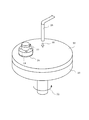
- FIG. 1 is an external view showing a schematic structure of a polishing abrasive according to the present invention.
- the polishing abrasive 10 of the present invention is used to polish various materials such as sapphire, silicon carbide and gallium nitride.
- the first component 12, the second component 13 and the reaction accelerator 14 each retain the material-specific properties of the individual components. As it is, they are directly coupled to each other by mechanical alloying processing.
- the first component 12 is a component that exerts a mechanical polishing action on the material to be polished.
- the second component 13 is a component that exerts a chemical polishing action on the material to be polished.
- the reaction accelerator 14 is a component that promotes the above-mentioned chemical polishing action in response to the frictional heat generated when the material to be polished is polished.
- the polishing abrasive 10 is obtained by integrating these components in the form of particles.
- the chemical polishing action includes an action of causing a mechanochemical effect on the surface of the material to be polished to deteriorate it.
- the chemical polishing action also includes an action of reacting with the frictional heat generated at the time of polishing treatment to oxidize the polishing surface of the material to be polished.
- the direct bonding of the plurality of components above means that materials other than the plurality of components are not used in bonding. It means that it bonds without using bonding materials, such as an adhesive agent.
- an amorphous layer 15 is formed at the boundary as shown in FIG. 1C.
- the components are bonded together through the amorphous layer 15.
- the inorganic compound components are bonded by the chemical activity of the amorphous layer 15 generated on the crystal surface by the mechanical alloying process. Due to this bonding force, each inorganic compound component is not easily separated either before or during polishing.
- each inorganic compound component is exhibited in a chain at the portion of the abrasive grains for polishing which is in contact with the material to be polished.
- the amorphous layer 15 formed on various places of the crystal surface of the second component and the third component also has the effect of enhancing the chemical polishing action of these.
- To be integrated in the form of particles means that it is selected to have a size and shape suitable for use as abrasive grains.
- the abrasive grains may be selected to have an average particle size of 10 ⁇ m or less.
- those having a larger particle size can also be used. Therefore, the polishing abrasive of the present invention can meet various surface roughness requirements.
- the abrasive grains for polishing may be in the form of an integrated block.
- the outer shape of the polishing abrasive may not be circular.
- Plural kinds of components are combined by mechanical alloying processing. Thus, multiple types of components are combined while retaining the material-specific properties of the individual components.
- a plurality of types of components are combined because the material-specific properties of each component are combined to polish the material to be polished.
- the polishing abrasive of the present invention does not use a chemical slurry containing an acid, an alkali, an oxidizing agent or the like when performing wet polishing. It has a feature that abrasive grains can be dispersed and used in neutral water.
- the first component exerts a mechanical polishing action on the material to be polished.
- the new Mohs hardness (modified Mohs hardness) of the first component 12 is selected according to the hardness of the material to be polished. For example, when the material to be polished is silicon carbide or gallium nitride, the composite particle is silicon carbide or gallium nitride at a high mechanical speed such that the new Mohs hardness of 7 or more and 13 or less is 7 or more. This is to provide the minimum hardness required for polishing.
- the reason for setting the new Mohs hardness to 13 or less is to use silicon carbide or gallium nitride particles having a hardness equal to or less than the hardness so as to polish the surface of silicon carbide or gallium nitride without significant damage.
- silicic acid compounds are suitable.
- SiC, Al 2 O 3 , ZrSiO 4 , ZrO 2 , talc or mica are suitable.
- Silicate compounds other than these are also applicable.
- soft talc or mica is suitable when obtaining a high-quality polished surface. That is, a silicate compound having a new Mohs hardness of less than 9 is suitable. When sapphire having a new Mohs hardness of 9 is polished, the new Mohs hardness of abrasive grains for polishing is preferably 7 or more and 9 or less.
- the first component 12 preferably accounts for 5 weight percent or more and 95 weight percent or less, where the total weight of the integrated particles is 100. If the blending ratio of the first component 12 is less than 5%, the hardness of the polishing abrasive may be insufficient. Also, if the blending ratio of the first component 12 exceeds 95%, the second component may be insufficient, and the improvement of the polishing rate by the chemical polishing action may be insufficient.
- the second component 13 produces a mechanochemical effect on the material to be polished.
- the cause of mechanochemical effect on the material to be polished means that at least the bonds between molecules or atoms on the surface of the material to be polished are cut or oxidized, and some molecules or atoms are combined with other molecules or atoms. It refers to acting as a replacement. In this way, by chemically altering the surface of the material to be polished, it is possible to peel off the altered portion with an abrasive that is equal to or softer than the material to be polished. Thereby, the surface of the material to be polished is planarized.
- this second component makes it possible to carry out polishing treatment at a high polishing rate (polishing rate per unit time) which could not be obtained so far.
- the second component 13 may be Cr 2 O 3 , Fe 2 O 3 , TiO 2 , ZnO, NiO, SnO 2 , Sb 2 O 3 , CuO, Co 3. It is preferable to select and use one or more oxides selected from the group of O 4 , CeO 2 , Pr 6 O 11 and MnO 2 .
- the second component is an oxide or double oxide of a transition metal element existing between Groups 3 and 11 on the periodic table except Zr or a Group 12 element (zinc group element) on the periodic table. is there.
- the multiple oxide is one in which any two or more of these oxides form a solid solution.
- Materials selected as the second component 13 include substances that easily oxidize silicon carbide or gallium nitride at high temperatures.
- the second components 13 listed in the above examples are all oxides, in particular MnO 2 is well known as a solid oxidizing agent, and the highly active manganese dioxide produced by the electrolytic process is suitable. Manganese dioxide is reacted by the frictional heat generated at the time of polishing treatment to oxidize the C surface of silicon carbide and to react solidly with the Si surface. The oxidized polished surface can be efficiently removed mechanically with a component of Mohs hardness equal to or less than silicon carbide.
- a material which is likely to have isomorphous substitution with aluminum ion (Al 3 + ) of sapphire is preferable.
- This material is a material whose ion radius is similar to that of aluminum (Al).
- silica (SiO 2 ) causes the substitution that occurs upon dehydration of the siloxane. Due to this chemical reaction, the surface of the material to be polished (sapphire) is altered, and efficient polishing is possible with the first abrasive having a hardness equal to or less than that of the material to be polished.
- the second component 13 preferably occupies 5 weight percent or more and 95 weight percent or less, where the total weight of the integrated particles is 100.
- the blending ratio of the second component 13 is less than 5%, the chemical polishing action may be insufficient and a sufficiently high polishing rate may not be maintained. If the proportion of the second component 13 exceeds 95%, the hardness of the abrasive grains may be insufficient as a whole.
- the reaction accelerator 14 is poorly soluble in pure water used as a slurry, and is made of an alkali metal salt or an alkaline earth metal salt.
- the reaction accelerator 14 is not liquid but solid. If the reaction accelerator 14 is solid, it can be integrated with the first component 12 and the second component 13 by mechanical energy to obtain abrasive grains. On the other hand, when the reaction accelerator 14 is a liquid or a material which is easily dissolved in water, the abrasive grains are decomposed in the slurry. Furthermore, the waste solution adversely affects the environment.
- the reaction accelerator 14 is one kind selected from the group of CaCO 3 , SrCO 3 , MgCO 3 , BaCO 3 , LiCO 3 , LiCO 3 , Ca 3 (PO 4 ) 2 , Li 3 PO 4 , AlK (SO 4 ) 2 Or it is preferable that they are 2 or more types of materials. It is sparingly soluble in pure water, and alkali metal salts or alkaline earth metal salts are suitable. Any material can promote the polishing function of the second component 13 by the frictional heat generated at the time of polishing. In addition, inorganic compounds that are poorly soluble in pure water and stable in air such as CaF 2 , Na 3 AlF 6 , Na 2 B 4 O 7 , AgCl, AgBr, Agl, etc. are suitable.
- the material selected as the reaction accelerator 14 has a solubility in pure water of 0.1 or less except for LiCO 3 and AlK (SO 4 ) 2 . That is, the amount dissolved in 100 grams of pure water at 25 degrees Celsius is 0.1 grams or less.
- the solubility of LiCO 3 in pure water is 1.33
- the solubility of AlK (SO 4 ) 2 is 6.74, which is larger than other materials.
- polishing abrasives they do not separate during polishing and dissolve in large amounts in pure water. That is, the reaction accelerator is made difficult to dissolve in pure water by unifying by mechanical processing. Therefore, the abrasive grains for polishing could be circulated together with the slurry and used repeatedly for polishing.
- “poorly soluble” means that the amount dissolved in 100 grams of pure water at 25 degrees Celsius is 7 grams or less.
- the reaction accelerator 14 preferably accounts for 5 weight percent or more and 95 percent or less, where the total weight of the integrated particles is 100. If the blending ratio of the reaction accelerator 14 is less than 5% by weight, the effect of promoting the polishing function of the second component 13 may be insufficient. If the proportion of the reaction accelerator 14 exceeds 95 weight percent, the amount of the second component 13 may be insufficient.
- lithium carbonate and alkaline earth carbonate are selected as reaction accelerators.
- the abrasive for polishing is rubbed on the material to be polished and frictional heat is locally generated.
- carbon dioxide is released from lithium carbonate and alkaline earth carbonate.
- the lithium oxide and the alkaline earth oxide produced here react instantaneously with the water to generate a high heat of hydration, and at the same time, the strongly alkaline substance lithium hydroxide and the alkaline earth hydroxide are produced.
- This phenomenon occurs in a minute region on the surface of the material in contact with the abrasive grains. Since the abrasive grains for polishing contain a component that causes a mechanochemical effect and a component that exerts a mechanical polishing action on the material to be polished, the mechanochemical effect is promoted in a chained manner, and that portion is efficient. It is scraped off.
- a fluorine compound or a halogen compound is selected as the reaction accelerator, it is considered that the following reaction occurs.
- atoms lose their covalent bond and are in a state called dangling bond.
- the electrons on the dangling bond are chemically active because they are unstable.
- fluorine ions are generated by the frictional heat.
- the dangling bond bonds with fluorine.
- a fluorine atom with high electronegativity distorts the crystal structure of the surface of the material to be polished. Thereby, the mechanochemical effect on the surface of the material to be polished is promoted.
- FIG. 2 is a schematic perspective view showing an example of a polishing apparatus using the polishing abrasive of the present invention.
- the polishing platen 20 is rotationally driven in the direction of the arrow 32.
- the upper surface of the polishing platen 20 is covered by a polishing pad 22.
- the holding device 24 is a device for pressing and supporting the material to be polished 26 (silicon carbide substrate or gallium nitride substrate) against the polishing pad 22.
- abrasive grains are supplied from the injector 28 in the direction of the arrow 30 together with the slurry.
- the material to be polished 26 pressed against the surface of the polishing pad 22 is polished in contact with the polishing abrasive.
- the slurry and the polishing abrasive are continuously supplied in fixed amounts during the polishing process.
- the polishing abrasive of the present invention can be used, for example, in polishing processes for sapphire substrates and silicon carbide or gallium nitride substrates for power devices.
- the sapphire substrate has a new Mohs hardness of 9.
- the silicon carbide substrate and the gallium nitride substrate have a new Mohs hardness of 13.
- polishing is performed until the surface roughness of the silicon carbide or gallium nitride substrate reaches 0.010 ⁇ m or less.
- a suspension obtained by dispersing abrasive grains for polishing in pure water can be supplied to a polishing surface to perform polishing treatment. Neutral water can be used for the slurry.
- a surfactant or a chelating agent may be added to the water to disperse the abrasive grains for polishing.
- the suspension produced by dispersing the polishing abrasive grain of the present invention in neutral water has a pH at 25 degrees Celsius of 4 or more and 11 or less, as described later. That is, the slurry can be kept in the weakly acidic or weakly alkaline range.
- the above-mentioned various substrates are double-sided polished so as to adjust their shapes first. This is called roughing. After that, intermediate processing is performed to reduce scratches caused by rough processing. Finally, finish processing is performed to polish the surface to atomic level flatness.
- diamond abrasive is used to polish a silicon carbide or gallium nitride substrate.
- the diamond abrasive has a Vickers hardness higher than that of a silicon carbide or gallium nitride substrate, it causes damage reaching a deep part from the surface, which is called a saw mark. In order to repair this polishing mark, it is necessary to perform long intermediate processing thereafter.
- the use of diamond abrasive for roughing is to improve the polishing rate as much as possible.
- the polishing abrasive of the present invention solves this problem.
- the use of the polishing abrasive of the present invention makes it possible to carry out roughing and intermediate processing all at once because a sufficiently high polishing rate can be obtained.
- the polishing abrasive grain of the present invention is polished using Component 3 which is as soft as silicon carbide or a gallium nitride substrate or softer than this.
- a polishing slurry in which the polishing abrasive of the present invention is dispersed at a concentration of 15% by weight in 100 ml of pure water is used.
- the pH of the slurry at 25 degrees Celsius is 4 or more and 11 or less.
- the waste liquid after the polishing treatment for 4 hours had a pH of about 8.
- the pH of the waste liquid is most preferably 5 or more and 9 or less, and was within this range when materials other than LiCO 3 and Ca 3 (PO 4 ) 2 were used.
- LiCO 3 and Ca 3 (PO 4 ) 2 were used as reaction accelerators, the pH was about 10-11. All of them are in the range of weak acidity to weak alkalinity, which can suppress the adverse effect on the working environment.
- waste liquid treatment is simplified.
- the above slurry contains 5 weight percent or more of abrasive grains for polishing with respect to 100 parts of pure water, and the apparent specific volume (static method) of the abrasive grains for polishing is 0.5 ml / g or more and 200 ml / g or less It is preferable to adjust so that If the apparent specific volume (static method) is less than 0.5 ml / g, the components of the polishing abrasive will separate. Even if the apparent specific volume (static method) exceeds 200 ml / g, there is no improvement in the polishing rate, the abrasive grains become excessive in the slurry and the sedimentation becomes intense.
- the holding device 24 is preferably made of synthetic fiber, glass fiber, natural fiber, synthetic resin, natural resin or the like.
- frictional heat can be generated effectively to realize a high polishing rate. It is preferable that frictional heat be generated between the abrasive grains for polishing and the material to be polished above a temperature at which a chemical reaction by the reaction accelerator occurs.
- the polishing abrasive of the present invention can also be used for dry polishing.
- the substrate is a polishing pad
- the polishing abrasive is dispersed and fixed to the surface of the pad with an appropriate density to obtain a polishing member. What fixed and disperse
- the abrasive grains and the plastic before solidification are mixed and then cured by a predetermined method to obtain an abrasive member.
- an abrasive member may be used.
- This polishing member is suitable for dry polishing, but can also be wet polished by supplying pure water to the polishing surface during polishing processing.
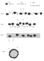
- FIG. 3 is an explanatory view of a conventional mechanochemical polishing method. These are all listed as comparative examples.
- the abrasive shown in FIG. 3A is a mixture of a plurality of abrasives.
- a abrasive 16 and B abrasive 18 are mixed and supplied to the polishing apparatus together with the slurry.
- the B abrasive 18 has a function of promoting the polishing action of the A abrasive 16.
- the specific gravity of the A abrasives 16 and B is different, as shown in FIG. 3B, both are separated in the slurry.
- FIG. 3C shows an example using a slurry 17 that promotes the polishing action of the A abrasive material 16.
- This method solves the above problems and is widely used in recent years.
- the slurry 17 is a strongly alkaline one or an oxidizing agent, and is a corrosive solution, the working environment is deteriorated.
- the treatment cost of the waste liquid after the polishing treatment is large.
- FIG. 3D shows an example in which the A abrasive 16 is fixed to the surface of the polymer material 19. It is difficult to obtain such abrasive grains having an average particle size suitable for the lapping process of hard and brittle materials. That is, only a large size can be obtained. In addition, the specific gravity is reduced as a whole, and it is washed away from the polishing apparatus. Since the polishing abrasive of the present invention has a heavy specific gravity, it stays on the upper surface of the pad of the polishing apparatus for a long time to improve the polishing rate.
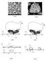
- FIG. 4A and Fig. 4B are microphotographs of abrasive grains of the present invention, and Fig. 4A and the subsequent figures are explanatory views of the abrading action.
- FIG. 4A is a microphotograph showing the abrasive grain of Example 1.
- FIG. Immediately after the integration treatment abrasive grains of various sizes are mixed. Those having an average particle diameter of 5 to 6 ⁇ m and a particle diameter of about 1 ⁇ m are also mixed.
- Fig 4B is a partial enlarged view thereof. This is a photograph of one polishing abrasive having an outer diameter of about 6 ⁇ m.
- the three types of previously crushed components are mixed and strongly integrated with each other.
- Each of the three components is integrated in the form of particles while retaining the inherent physical and chemical properties inherent in the components.
- the abrasive grains of the example are integrated with a force that does not separate even after being used for the polishing process. For example, the surface condition of the polishing abrasive collected after polishing the silicon carbide substrate for 4 hours was also indistinguishable from this photograph.
- the abrasive grain of Example 1 is obtained by integrating aluminum oxide (Al 2 O 3 ), manganese dioxide (MnO 2 ) and calcium carbonate (CaCO 3 ). These were mixed in proportions of 50 parts by weight, 37.5 parts by weight, and 12.5 parts by weight, respectively. These were ground to a powder having an outer diameter of 1 ⁇ m or less by a ball milling method, and mechanical impact was continued for about 0.5 hours to obtain abrasive grains. Among them, polishing abrasives having an average particle size of 1 ⁇ m were selected and used. The abrasive grains for polishing obtained by the above method were supplied to the apparatus shown in FIG. 2 together with pure water, and the silicon carbide substrate was polished for 4 hours. The slurry containing the abrasive grains is supplied onto the polishing pad 22 during the polishing process and sequentially discharged. The discharged slurry was collected again, supplied onto the polishing pad 22 and could be used repeatedly.
- Al 2 O 3 aluminum oxide
- Al 2 O 3 aluminum oxide
- SiO 2 silicon oxide
- CaCO 3 calcium carbonate
- a method is known in which a plurality of inorganic compound components are bonded using an adhesive such as a resin.
- an adhesive such as a resin
- the bonding force of an adhesive such as a resin can not prevent the plurality of inorganic compound components from being separated from each other by an external force received during polishing.
- a method of sintering and integrating the respective components is conceivable.
- the inorganic compound components mix with each other, and the inherent properties of the individual inorganic compound components are largely lost. Therefore, the function of the abrasive grain of the present invention can not be exhibited effectively. That is, a sufficiently efficient polishing rate can not be realized.
- the components are degraded or decomposed by the heat of about 1000 ° C. received in the sintering process.
- the mechanical alloying process does not add heat that degrades or decomposes each component.
- the respective components of the polishing abrasive of this example are uniformly mixed, part of each of the components is exposed on the outer surface of the polishing abrasive.
- the abrasive grains are in direct continuous contact with the material to be rolled as it rolls.
- the abrasive grains themselves generate heat due to frictional heat, and the chemically reactive abrasive is directly heated by the frictional heat to produce a mechanochemical effect on the surface of the workpiece.
- the component of the abrasive grains for polishing which mechanically cuts the surface of the material to be polished contacts the portion where the mechanochemical effect is occurring. From this, the portion where the mechanochemical effect of the material to be polished is generated is scraped.
- the abrasive grains move in such a manner as to roll on the surface of the material to be polished.
- the chemically reactive abrasive and the component having the function of mechanically scraping the abrasive are alternately repeated and brought into contact with the surface of the abrasive.
- the polishing process proceeds efficiently in a chain.
- polishing can also be coated with one of the components. In this case, the other components are not exposed to the outer surface of the abrasive grain.
- the coating breaks down and all components are exposed to the surface during the polishing process, the above-mentioned effect occurs.
- all the components may not be exposed on the surface of the abrasive grain for polishing.
- FIG. 4E is a cross-sectional view of the vicinity of the surface of the workpiece when the workpiece is polished with the polishing abrasive of the example. Only the hatched portion near the surface of the material to be polished 26 is scraped off.
- FIG. 4F is a cross-sectional view of the vicinity of the surface of the material to be polished when the surface of the material to be polished 26 is polished with the diamond abrasive grains 36. In this case, deep polishing marks 38 occur on the surface of the material to be polished 26. This has been the most problematic in the past.
- FIG. 5A is a diagram comparing the components of the polishing abrasive before and after the silicon carbide substrate is polished for 4 hours.
- the upper part of FIG. 5A shows the proportion of each component of the polishing abrasive before polishing treatment.
- the lower part shows the proportion of each component of the polishing abrasive after the polishing treatment.
- the polishing abrasive of the example has no significant change in the component ratio before and after the polishing treatment.
- the abrasive grain of the present invention has high mechanical strength and can be used repeatedly since it is not broken even by the polishing treatment.
- FIG. 5B is a diagram comparing the components of the composite abrasive before and after polishing the sapphire substrate for 4 hours.
- the proportions of aluminum (Al), silicon (Si) and calcium (Ca) in the total were 38.2 wt%, 43.8 wt%, and 17.9 wt%, respectively.
- After the polishing treatment they were 41.2 wt%, 42.3 wt%, and 16.5 wt%.
- the ratio of the components other than the aluminum component to the total was almost unchanged.
- the cause of the increase in the proportion of the aluminum component is considered to be because polishing debris obtained by polishing sapphire is newly included.
- Mullite is a compound of aluminum oxide and silicon dioxide. Its chemical formula is represented by 3Al 2 O 3 ⁇ 2SiO 2 ⁇ 2Al 2 O 3 ⁇ SiO 2 or Al 6 O 13 Si 2,.
- the friction between the composite abrasive and the material to be polished generates frictional heat of several hundred degrees Celsius locally. The heat diffuses due to the slurry, but the minute region where the composite abrasive and the material to be polished are in contact becomes high temperature. As a result of the reaction of the material to be polished and the aluminum oxide being promoted by calcium carbonate, it can be judged that mullite is formed.
- FIG. 6 is a characteristic comparison diagram of waste liquid resulting from polishing processing using various abrasive grains.
- the temperature was raised from room temperature to about 30 ° C. to 40 ° C. by the polishing process, so the influence by the reaction accelerator could be confirmed .
- the residue of the slurry discharged after the polishing process except pure water is shavings of a silicon carbide or gallium nitride substrate.
- the residue is a solid component and can be removed from the waste by a filter.
- most of the waste liquid had a pH of about 7.5.
- the drainage is neutral and easy to treat, and there is no problem of environmental pollution.
- the maximum pH is 11.2, which can be processed without problems.
- FIG. 7 is a comparison diagram of polishing rates when the first component is replaced and SiC is polished.
- the portion denoted as Sample 1-1 shows the result of using polishing abrasives in which Al 2 O 3 , MnO 2 and CaCO 3 are integrated for polishing silicon carbide.
- the operating conditions of the polishing apparatus are 50 revolutions per minute (rpm) of the polishing table 20, 100 revolutions of the holding unit 24 per minute, and the holding unit 24 polishes the workpiece 26.
- the polishing pressure for pressing in the direction of the platen 20 was 160 grams per square centimeter (g / cm 2 ).
- the abrasive grains are mixed in pure water at 15% by weight.
- the slurry thus prepared was supplied onto the polishing pad 22 from the injector 28 at a rate of 10 milliliters per minute (ml / min).
- sample 2-1 shows the result of using polishing abrasives in which ZrO 2 , MnO 2 and CaCO 3 are integrated for polishing silicon carbide.
- Sample 2-2 has a first component of ZrSiO 4
- sample 2-3 has a first component of mica
- sample 2-4 has a first component of talc.
- the first component has no action to produce a mechanochemical effect.
- the new Mohs hardness of the first component ZrO 2 is 11.
- the new Mohs hardness of silicon carbide is 13. Silicon carbide can not be polished with the first component alone.
- the polishing abrasive in which the first component ZrO 2 , the second component MnO 2 and the reaction accelerator CaCO are integrated has the highest polishing rate as shown in the figure. While the polishing rate when using the conventional diamond abrasive shown in Comparative Example 6 of FIG. 8 is 0.26 ( ⁇ m / min), the polishing rate of Sample 1-1 is about 2 .8 times 0.72 ( ⁇ m / min). The action of the first component on gallium nitride is substantially similar. Therefore, this experiment is not shown for gallium nitride.
- FIG. 8 is a comparison diagram of polishing rates when the second component is replaced and the SiC is polished.
- the portion denoted as Sample 1-1 shows the result of using polishing abrasives in which Al 2 O 3 , MnO 2 and CaCO 3 are integrated for polishing silicon carbide.
- the example of FIG. 8 shows an example in which the first component and the reaction accelerator are the same and the second component is replaced in order.
- Sample 3-1 has TiO 2 as the second component, ZnO has the second component as sample 3-2, NiO as the second component as sample 3-3, SnO 2 as the second component as sample 3-4.
- Sample 3-5 is the second component Sb 2 O 3
- sample 3-6 is the second component CuO
- sample 3-7 is the second component Co 3 O 4
- sample 3-8 is the second The component is CeO 2
- the sample 3-9 is a complex oxide in which the second component is Pr 6 O 11 and the sample 3-10 is a second component Ti—Cr—Sb.
- Samples 3-11 and 3-12 are abrasive grains having a two-component structure.
- Sample 3-11 shows the result of using a polishing abrasive in which aluminum oxide (Al 2 O 3 ) and manganese dioxide (MnO 2 ) are mechanically bonded and integrated in the same manner as the present invention.
- Samples 3-12 show the results of using a polishing abrasive in which calcium carbonate (CaCO 3 ) and manganese dioxide (MnO 2 ) are mechanically bonded and integrated in the same manner as the present invention. Even in the case of two components, it was possible to obtain the same polishing rate as when using conventional diamond abrasive grains.
- Comparative Example 1 shows the results of using a polishing abrasive in which aluminum oxide (Al 2 O 3 ) and calcium carbonate (CaCO 3 ) are mechanically bonded and integrated in the same manner as the present invention.
- Comparative Example 2 shows the results of using a mere mixture (not integrated) of aluminum oxide (Al 2 O 3 ), manganese dioxide (MnO 2 ) and calcium carbonate (CaCO 3 ) in the slurry.
- Comparative Example 3 shows the result of using only manganese dioxide (MnO 2 ) as the abrasive.
- Comparative Example 4 shows the result of using only aluminum oxide (Al 2 O 3 ) as the abrasive.
- Comparative Example 5 shows the result of using only calcium carbonate (CaCO 3 ) as the abrasive.
- Comparative Example 6 shows the results of using an oil-based slurry using diamond abrasive grains having an average particle size of 1 to 3 ⁇ m, using a metal platen as a polishing apparatus.
- Sample 1-1 shown in FIG. 8 exhibits a very high polishing rate, and can be said to be sufficiently effective for polishing SiC. It can be said that Samples 3-11 and 3-12 also have higher polishing rates than in the prior art, and their practicability is sufficiently high.
- the polishing rates of other samples are as follows when using diamond abrasives. However, these samples have the advantage of not producing harmful waste liquid and the advantage that the polishing surface is of extremely high quality, and can be said to be superior to the conventional method. That is, since the second abrasive grains are integrated with the abrasive grains for polishing, there is an effect that the second abrasive grains are not easily eluted in the slurry and the slurry is not largely contaminated.
- All samples use a slurry containing pure water as a dispersion medium, which does not deteriorate the working environment and facilitates waste liquid treatment.
- the surface of the metal platen used for polishing should be as flat as required for polished surfaces of silicon carbide and gallium nitride. However, maintaining its flatness is not easy.
- the resin pad is merely to apply pressure to press the polishing abrasive on the polishing surface of silicon carbide or gallium nitride. Therefore, a highly accurate structure is not required. Resin pads are inexpensive and easy to maintain.
- FIG. 9 is a comparison diagram of polishing rates of gallium nitride GaN when the second component is replaced.
- the abrasive grains of Samples 1-1 and 3-1 to 3-11 each have the same structure as the abrasive grains of the same sample name in FIG.
- Sample 1-1 showed a very high polishing rate.
- Samples 3-9 and 3-10 also showed high polishing rates.
- Samples 3-2, 3-3-3-4, 3-6 also exhibited high polishing rates comparable to Comparative Example 8.
- the other samples have a low polishing rate, but have no harmful waste solution and an advantage that the polishing surface has a very high quality, as in the case of FIG.
- the first component has a low New Mohs hardness such as talc and mica, a polishing rate comparable to or higher than that of diamond abrasive can be realized. In addition, it is very effective because a very high quality polishing surface can be obtained.
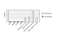
- FIG. 9B is a comparison diagram of the results of polishing treatment of sapphire using various abrasive grains.
- the portion denoted as sample 1 shows the result of using composite abrasives in which Al 2 O 3 , SiO 2 and CaCO 3 are integrated for polishing sapphire.
- the portion denoted as sample 2 shows the result of using composite abrasives in which Al 2 O 3 , Fe 2 O 3 and CaCO 3 are integrated for polishing sapphire.
- sample 3 shows the result of using composite abrasives in which Al 2 O 3 , Cr 2 O 3 and CaCO 3 are integrated for polishing sapphire.
- sapphire wafers were polished with GC (green carbonite) having an average particle size of # 325, and those having a surface roughness Ra of 0.22 ⁇ m were used as the polishing agent.
- the operating conditions of the polishing apparatus are 50 revolutions per minute (rpm) of the polishing table 20, 100 revolutions of the holding device 24, and the direction of the polishing plate 26 with the holding device 24.
- the polishing pressure for pressing the was 160 grams per square centimeter (g / cm 2).
- the composite abrasive is mixed in pure water at 15% by weight.
- the slurry thus prepared was supplied onto the polishing pad 22 from the injector 28 at a rate of 1 milliliter per minute (ml / min).
- Ref 1 shows the result of using only aluminum oxide (Al 2 O 3 ) as an abrasive.
- ref2 shows the results of only silicon oxide (SiO 2) was abrasive.
- ref3 shows the results of only calcium carbonate (CaCO 3) was abrasive.
- Ref 4 shows the result of using a composite abrasive in which aluminum oxide (Al 2 O 3 ) and silicon oxide (SiO 2 ) are mechanically combined and integrated in the same manner as the present invention.
- ref5 shows the results of using the composite abrasive particles mechanically coupled integrated aluminum oxide (Al 2 O 3) and calcium carbonate (CaCO 3) in the present invention the same method.
- ref6 shows the results of using the composite abrasive particles mechanically coupled integrated silicon oxide (SiO 2) and calcium carbonate (CaCO 3) in the present invention the same method.
- Ref 7 shows the result of using a mixture (not integrated) of aluminum oxide (Al 2 O 3 ), silicon oxide (SiO 2 ) and calcium carbonate (CaCO 3 ) in the slurry.
- Ref 8 shows the result of using a diamond abrasive having an average particle size of 1 to 3 ⁇ m.
- a resin pad was used as a polishing pad, and a slurry in which abrasive grains were mixed in pure water was used.
- ref 9 shows the result of using an oily slurry, using a diamond abrasive having an average particle diameter of 1 to 3 ⁇ m, using a metal platen in a polishing apparatus.
- the polishing rates of all the examples were 1 ⁇ m / min when using the composite abrasive grain of sample 1, but in the examples of ref1 to ref8, all were approximately at about 1 min / min. It can not exceed 0.3 ⁇ m. Also in the example of ref 9, the polishing rate is 0.8 ⁇ m / min, which is less than the polishing rate of the present invention.
- the example of ref 9 is a method known to have the highest polishing rate.
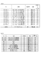
- FIG. 10 is data showing the relationship between the polishing rate of SiC and the temperature after the polishing process when the reaction promoter is replaced.
- the comparative example 1 is an example using the abrasive grain which does not contain a reaction promoter.
- Samples 11 to 18 are experimental results of polishing abrasives using Al 2 O 3 as the first component and MnO 2 as the second component and using different reaction promoters. The results of measuring the polishing rate and the temperature of the slurry after polishing silicon carbide for 4 hours were displayed.
- Sample 19 is an example using a polishing abrasive in which only a reaction promoter (CaCO 3 ) and the second component MnO 2 are integrated.
- Sample 20 is an example using a polishing abrasive in which only a reaction accelerator (CaCO 3 ) and the first component Al 2 O 3 are integrated.
- the polishing rate in the case of Comparative Example 1 was 0.31 ⁇ m / min, and the temperature of the slurry after polishing was 27 ° C.
- the temperature of the slurry after polishing was 27 ° C.
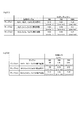
- FIG. 10B is a table showing the relationship between the temperature of the slurry after polishing and the polishing rate.
- Experimental Examples 1 to 8 experimental results using composite abrasives using Al 2 O 3 as the first abrasive and SiO 2 as the second abrasive and using different reaction accelerators respectively It is.
- Each of these composite abrasive grains is composed of 50% by weight of the first abrasive, 37.5% by weight of the second abrasive, and 12.5% by weight of the reaction accelerator, as a percentage of the total. ing.
- the polishing conditions are all the same.
- the material to be polished has a surface roughness Ra of 0.22 ⁇ m after polishing a sapphire wafer with GC (green carbonite) of average particle size # 325.
- the temperature of the slurry before polishing was 25 degrees Celsius.
- the temperature of the slurry after polishing the sapphire for 1 hour was measured.
- the polishing rate is obtained by measuring the thickness of the material to be polished after polishing and calculating the polishing amount per minute (min).
- ref1 is a comparative example using an abrasive that does not use a reaction accelerator.
- Ref 2 is a comparative example using only a reaction promoter (CaCO 3 ) and a second polishing agent SiO 2 .
- Ref 3 is a comparative example using only a reaction promoter (CaCO 3 ) and the first abrasive Al 2 O 3 .
- the polishing rate in the case of ref1 was 0.40 ⁇ m / min, and the temperature of the slurry after polishing was 27 ° C.
- the slurry was heated to 41 degrees Celsius by the heat generation of the reaction accelerator for ref2 (without the first abrasive) and ref3 (without the second abrasive).
- the polishing rate is not very high. This proves that only the composite abrasive grain of the present invention in which the first abrasive, the second abrasive and the reaction accelerator are combined has a sufficiently high polishing rate.
- the particles having a Mohs hardness of 13 or less are ZrSiO 4 , Al 2 O 3 , ZrO 2, and SiC. These components act to apply a physical force to silicon carbide or gallium nitride to form a plastic deformation layer (amorphous layer).
- the second component having the property of causing a mechanochemical effect after the alteration of the plastically degraded layer, the first component acts to mechanically peel off the plastically deformed layer. If the plastically deformed layer is formed of the first component in the material to be polished, the crystal structure of that portion is broken, so it is considered that the mechanochemical effect by the second component is likely to be generated. When the plastically altered layer is altered, it is possible to peel it off with the first abrasive having a hardness lower than that of the material to be polished. This action is the same as in the case where the material to be polished is sapphire.
- Al 2 O 3 has a new Mohs hardness of 9.
- ZrSiO 4 and ZrO 2 have a new Mohs hardness of 8. Since neither particle has a new Mohs hardness higher than silicon carbide or gallium nitride, the generation of polishing marks is suppressed. Since Al 2 O 3 is harder than the ZrSiO 4, than abrasive grains using ZrSiO 4, a high polishing rate towards the abrasive grains using Al 2 O 3.
- the mechanochemical abrasive is Cr 2 O 3 , Fe 2 O 3 , TiO 2 , ZnO, NiO, SnO 2 , Sb 2 O 3 , CuO, Co 3 O 4 , CeO 2 , Pr 6 O 11 and MnO 2 . Both are susceptible to oxidation reaction with silicon carbide or gallium nitride in a high temperature atmosphere. It is also prone to cause solid phase reaction. This chemical reaction is considered to alter the polished surface of silicon carbide or gallium nitride. This is as introduced in the prior art document.
- the mechanochemical abrasive for sapphire is Cr 2 O 3 , Fe 2 O 3 or SiO 2 . These abrasives are susceptible to isomorphous substitution with sapphire (Al 2 O 3 ). Homomorphic substitution is a phenomenon in which substances having similar ion radii are mutually replaced by an ion group when pressure or heat is applied from the outside.
- Substances with an ionic radius close to that of sapphire (six-coordination) Al 3 + (ion radius 0.54 ⁇ (angstrom)) are hexacoordinated Fe 3 + (ion radius 0.55 ⁇ ) or Fe 2 O 3 , Cr 2 O 3 hexacoordinate Cr 3 + (ion radius 0.62 ⁇ ). These groups of ions undergo isomorphic substitution. This chemical reaction is considered to alter the polished surface of sapphire.
- SiO 2 undergoes the following chemical reaction.
- SiO 4 tetrahedrons having a silanol group ⁇ Si—OH
- Al 3 + participates in the dehydration condensation reaction in the form of Al (OH) 3 .
- the SiO 4 linkage is incorporated into the crystal structure of sapphire.
- hexacoordinated Si 4 + ion radius of 0.40 ⁇
- tetracoordinated Al 3 + ion radius of 0.39 ⁇
- the abrasive grains for polishing form a plastic deformation layer on the polished surface of silicon carbide or gallium nitride, and cause a mechanochemical effect at the portion where the high temperature strong alkaline atmosphere is formed by the reaction accelerator, and carbonize it. Polish silicon and gallium nitride. By this heat generation, the slurry after polishing became 30 degrees Celsius to 40 degrees Celsius. The strong alkaline atmosphere is generated in a very narrow area around the abrasive grains and does not greatly affect the pH of the entire slurry.
- FIG. 11 is data showing the relationship between the polishing pressure and the polishing rate of Samples 1 to 3. This example is to confirm the change of the polishing rate due to the change of the polishing pressure.
- three types of polishing pressure per one square centimeter 500 g / cm 2 , 750 g / cm 2 ) and 1000 g / cm 2 are used as the holding device 24 presses the material 26 in the direction of the polishing platen 20.
- the experimental results of The plate rotation number was 50 rotations per minute, the carrier rotation number was 100 rotations per minute, the slurry concentration was 15%, and the slurry supply amount was 10 ml per minute.
- the polishing rate of the SiC substrate is improved.
- the polishing rate is 0.72 ⁇ m / min ( ⁇ m / min)
- the polishing pressure is 1000 g / cm 2 .
- the result was that the polishing rate was 1.39 ⁇ m / min.
- the polishing rate was approximately doubled.
- the surface roughness of the silicon carbide substrate after polishing can be 0.003 ⁇ m without any polishing marks.
- polishing abrasives efficiently scrape the polishing surface of the workpiece.
- any of the polishing abrasives of Samples 1 to 3 high-quality polishing of the material to be polished can be performed at a higher speed than any of the conventional methods.
- FIG. 12 is a comparison diagram showing the relationship between the polishing rate and surface roughness of various composite abrasives.
- This example shows the polishing rates of various abrasive particles and the surface roughness of the material to be polished after polishing when pure water is used as a slurry.
- a single body of SiO 2 , MnO 2 , CeO 2 , TiO 2 and an example using diamond abrasives were included.
- Abrasive grains other than diamond abrasive grains have a very low polishing rate and become impractical for polishing SiC.
- the abrasive grains of the present invention show a polishing rate higher than that of the diamond abrasive grains, even when pure water is used for the slurry.
- the surface roughness of the polished SiC substrate is significantly smaller than that of the diamond abrasive. That is, a high quality polished surface can be obtained.
- FIG. 13 is a comparison diagram showing the relationship between the polishing rate of the abrasive grains of the comparative example and the surface roughness.
- the results of polishing a SiC substrate with SiO 2 , MnO 2 , CeO 2 , TiO 2 , and H 2 O 2 as an oxidant included in a slurry are shown.
- polishing is slightly possible.
- this polishing rate it takes too much time to polish and is not practical.
- FIG. 14 is a graph comparing the polishing rates.
- FIG. 15 is a graph comparing the surface roughness after polishing. The results of FIGS. 12 and 13 are shown graphically in FIGS. 14 and 15, respectively.
- the polishing abrasive of the present invention can realize a polishing rate equal to or higher than that of diamond abrasive.
- an overwhelmingly high-quality polished surface can be obtained as compared with the roughness of the polished surface by the diamond abrasive grains.
- the region in which the reaction accelerator generates frictional heat and the region in which manganese dioxide exerts an oxidizing action are extremely narrow. Moreover, the time for the effect to appear is also very short.
- the frictional heat promotes the oxidizing action of the second component, and the first component immediately contacts the corresponding surface in that state, thereby enabling effective polishing by interaction. Even if the reaction promoter, the oxidizing agent and the mechanical abrasive alternately contact the surface of the material to be polished for an irregular period of time, sufficient interaction does not appear. That is, there is a significant difference between the case where these particles are dispersed in the slurry and the case of the integrated polishing abrasive as in the present invention. This is the reason why the polishing abrasive of the present invention has dramatically improved the polishing rate.
- the intermediate process for polishing the material to be polished is compressed in a short time, and the polishing surface having high flatness is generated, so that the finishing process can be significantly shortened. Therefore, the present invention can greatly contribute to the cost reduction of the polishing process which greatly affects the production cost of this type of substrate. Further, since the abrasive grains for polishing are dispersed in neutral water without using a strongly acidic or strongly alkaline aqueous solution, the waste liquid is weakly acidic or weakly alkaline and does not adversely affect the environment.
- polishing abrasive of the present invention enables high-quality, high-speed polishing even with other materials.
- examples in which two-component or three-component inorganic compounds are combined are shown.
- polishing abrasives in which four or more types of inorganic compound components are integrally bonded to each other via an amorphous layer also have the same function.
- the mixing ratio and the combination of components may be freely selected according to the type of the material to be polished.
- the polishing abrasive of the present invention can be widely used in the polishing process of sapphire, silicon carbide or gallium nitride used for substrates for power devices, other electronic component materials, electrically insulating materials and the like. Furthermore, the abrasive grain of the present invention can also be used for high quality grinding of biomaterials such as metals, ceramics, or artificial bones. In addition, it can be used for polishing hard materials such as tungsten. And, compared to the conventional polishing method, the polishing time can be shortened significantly, and the cost of the product can be reduced significantly.
Abstract
Description
さらに、本発明は、環境に影響の少ないスラリーを使用して被研磨材を湿式研磨する研磨方法と研磨装置と研磨用のスラリーを提供することを目的とする。
被研磨材と等しいかもしくは被研磨材よりもモース硬度が低い粒子状の第1の研磨剤と、上記被研磨材を化学的に変質させる粒子状の第2の研磨剤とを、メカニカルアロイ法により粒子状に一体化させた研磨用砥粒。
上記第1の研磨剤は、上記一体化された粒子の5重量パーセント以上95重量パーセント以下を占める構成1に記載の研磨用砥粒。
上記第2の研磨剤は、上記一体化された粒子の5重量パーセント以上95重量パーセント以下を占める構成1に記載の研磨用砥粒。
上記第1の研磨剤と第2の研磨剤とを、平均粒径0.05μm以上100μm以下の粒子状に一体化させた構成1乃至3のいずれかに記載の研磨用砥粒。
機械的研磨性を持った成分と化学的研磨性を持った成分とが一体化した粒子であって、メカニカルアロイング処理によって両成分が接合したことを特徴とする研磨用複合砥粒。
被研磨材の表面を研磨するための粒子であって、この粒子は、メカニカルアロイング処理により結合された複数種類の無機化合物成分を含み、各無機化合物成分は、個々の成分の物質固有の性質を保持した状態で、相互に非晶質層を介して一体に結合している構成1乃至5のいずれかに記載の研磨用砥粒。
上記複数種類の無機化合物成分は、個々の成分の物質固有の性質を保持した状態で結合され、各無機化合物成分は、それぞれその一部が粒子の外表面に露出している構成6に記載の研磨用砥粒。
複数種類の無機化合物成分のいずれかに、被研磨材に対してメカノケミカル効果を生じさせる化学反応性研磨材が含まれている構成6または7に記載の研磨用砥粒。
複数種類の無機化合物成分はいずれも、被研磨材とモース硬度が等しいかもしくは被研磨材よりもモース硬度が低い構成8に記載の研磨用砥粒。
複数種類の無機化合物成分のいずれかに、被研磨材に対してメカノケミカル効果を生じさせる化学反応性研磨材と、被研磨材のメカノケミカル効果を生じた表面を機械的に削る成分が含まれている構成8に記載の研磨用砥粒。
被研磨材の表面を機械的に削る成分は、被研磨材と等しいかもしくは被研磨材よりもモース硬度が低い構成10に記載の研磨用砥粒。
被研磨材に対してメカノケミカル効果を生じさせる化学反応性研磨材は、研磨処理時に発生する摩擦熱により反応して被研磨材の研磨面を酸化させる成分である構成10に記載の研磨用砥粒。
被研磨材に対してメカノケミカル効果を生じさせる化学反応性研磨材は、リチウム,アルカリ土類金属の炭酸塩,リン酸塩,フッ化物,ホウ素化合物,及び塩化銀,臭化銀,ヨウ化銀等のハロゲン化合物、氷晶石,又はミョウバンの中から選択された1種または2種以上の難溶性の塩である構成10に記載の研磨用砥粒。
複数種類の無機化合物成分の原料を混合し、乾式状態でメカニカルアロイング処理を行い、各無機化合物成分を、相互に非晶質層を介して一体に結合させて粒子状にする研磨用砥粒の製造方法。
純水中に、構成1乃至12のいずかに記載の研磨用砥粒を分散させたスラリーを使用して、被研磨材を研磨する研磨方法。
基材に、構成1乃至12のいずかに記載の研磨用砥粒を分散させて固定した研磨部材。
合成繊維、ガラス繊維、天然繊維、合成樹脂、天然樹脂のいずれかにより構成され、構成1乃至12のいずかに記載の研磨用砥粒を表面に分散させて固定した研磨パッドと、
被研磨材を研磨パッド表面に向かって弾力を用いて押しつける保持装置と、
研磨面に純水を供給する注液器とを備え、
上記保持装置による弾力は、上記研磨用砥粒と上記被研磨材との間に、上記反応促進剤による化学反応が生じる温度以上に摩擦熱を発生させるレベルに設定される研磨装置。
中性の水の中に、構成1乃至12のいずかに記載の研磨用砥粒を分散させて生成した懸濁液であって、摂氏25度におけるpHが4以上11以下の、炭化ケイ素または窒化ガリウムを研磨するためのスラリー。
サファイアを湿式研磨するための砥粒であって、
モース硬度が7以上9以下の粒子状の第1の研磨剤と、
上記被研磨材に対してメカノケミカルな作用を有する粒子状の第2の研磨剤と、
スラリーのために使用する純水に対して難溶性のものであって、アルカリ金属塩またはアルカリ土類金属塩からなる粒子状の摩擦熱反応剤の混合物が、
メカニカルアロイ法により直接結合され粒子状に一体化されている複合砥粒。
上記第1の研磨剤は、Al2O3、ZrSiO4またはZrO2であって、上記一体化された粒子の5重量パーセント以上95重量パーセント以下を占める構成19に記載の複合砥粒。
上記第2の研磨剤は、Cr2O3、Fe2O3、SiO2の群の中から選択された、一種または2種以上の材料であって、上記一体化された粒子の5重量パーセント以上95重量パーセント以下を占める構成19に記載の複合砥粒。
上記第2の研磨剤としてSiO2を選択したとき、上記第1の研磨剤として、SiO2よりもモース硬度が大きいものが選択される構成19に記載の複合砥粒。
上記摩擦熱反応剤は、CaCO3、SrCO3、MgCO3、BaCO3、Li2CO3、Ca3(PO4)2、Li3PO4及びAlK(SO4)2の群の中から選択された、一種または2種以上の材料であって、上記一体化された粒子の5重量パーセント以上95重量パーセント以下を占める構成19に記載の複合砥粒。
上記第1の研磨剤は、Al2O3、ZrSiO4またはZrO2であって、
上記第2の研磨剤は、Cr2O3、Fe2O3、SiO2の群の中から選択された、一種または2種以上の材料であって、
上記摩擦熱反応剤は、CaCO3、SrCO3、MgCO3、BaCO3、Li2CO3、Ca3(PO4)2、Li3PO4及びAlK(SO4)2の群の中から選択された、一種または2種以上の材料である構成19に記載の複合砥粒。
構成1または6に記載の第1の研磨剤と第2の研磨剤と摩擦熱反応剤とを、メカニカルアロイ法により結合させて平均粒径0.05μm以上100μm以下の粒子状に一体化させた複合砥粒。
構成19または24に記載の第1の研磨剤と第2の研磨剤と摩擦熱反応剤とを、メカニカルアロイ法により結合させて平均粒径0.05μm以上100μm以下の粒子状に一体化する複合砥粒の製造方法。
純水中に構成19または24に記載の複合砥粒を分散させたスラリーを使用して、上記被研磨材を湿式研磨する研磨方法。
100ミリリットルの純水中に上記複合砥粒を15重量パーセントの濃度で分散させてスラリーを構成したとき、摂氏25度におけるpHが5以上9以下となるように構成19または24に記載の複合砥粒の配合を選定した、サファイアを湿式研磨する研磨方法。
構成19または24に記載の複合砥粒のみかけ比容(静置法)が、0.5ml/g以上200ml/g以下であるようにした、サファイアを湿式研磨するためのスラリー。
合成繊維、ガラス繊維、天然繊維、合成樹脂、天然樹脂のいずれかにより構成されるパッド上に構成9乃至11のいずれかに記載のスラリーを供給する装置と、被研磨材を上記パッドに弾力を用いて押しつけて、上記パッドの上面に分散した複合砥粒と上記被研磨材との間に摩擦を発生させる押圧装置とを備えた研磨装置。
合成繊維、ガラス繊維、天然繊維、合成樹脂、天然樹脂のいずれかにより構成されるパッド上に構成1または6に記載の複合砥粒を分散させて固定し、かつ、上記パッド上に純水を供給する装置と、被研磨材を上記パッドに弾力を用いて押しつけて、上記パッドの上面に分散した複合砥粒と上記被研磨材との間に摩擦を発生させる押圧装置とを備えた研磨装置。
炭化ケイ素または窒化ガリウムを被研磨材とする砥粒であって、上記被研磨材に対して化学的研磨作用を発揮する成分と、上記被研磨材を研磨する際に発生する摩擦熱に反応して上記の化学的研磨作用を促進する反応促進剤とが、それぞれ個々の成分の物質固有の性質を保持したまま、メカニカルアロイング処理によって相互に直接結合されて全体として粒子状に一体化されている研磨用砥粒。
炭化ケイ素または窒化ガリウムを被研磨材とする砥粒であって、上記被研磨材に対して機械的研磨作用を発揮する成分と、上記被研磨材に対して化学的研磨作用を発揮する成分とが、それぞれ個々の成分の物質固有の性質を保持したまま、メカニカルアロイング処理によって相互に直接結合して全体として粒子状に一体化されている研磨用砥粒。
炭化ケイ素または窒化ガリウムを被研磨材とする砥粒であって、上記被研磨材に対して機械的研磨作用を発揮する成分と、上記被研磨材に対して化学的研磨作用を発揮する成分と、上記被研磨材を研磨する際に発生する摩擦熱に反応して上記化学的研磨作用を促進する反応促進剤とを含む成分が、それぞれ個々の成分の物質固有の性質を保持したまま、メカニカルアロイング処理によって相互に直接結合して全体として粒子状に一体化されている研磨用砥粒。
炭化ケイ素または窒化ガリウムを被研磨材とする砥粒であって、
研磨処理時に発生する摩擦熱により反応して被研磨材の研磨面を酸化させる成分と、研磨時に発生する摩擦熱によって研磨面の酸化作用を促進する成分とが、それぞれ個々の成分の物質固有の性質を保持したまま、メカニカルアロイング処理によって相互に直接結合して全体として粒子状に一体化されている研磨用砥粒。
炭化ケイ素または窒化ガリウムを被研磨材とする砥粒であって、
研磨処理時に発生する摩擦熱により反応して被研磨材の研磨面を酸化させる成分と、研磨時に発生する摩擦熱によって研磨面の酸化作用を促進する成分と、酸化した被研磨材の研磨面を機械的に除去する成分とが、それぞれ個々の成分の物質固有の性質を保持したまま、メカニカルアロイング処理によって相互に直接結合して全体として粒子状に一体化されている研磨用砥粒。
上記機械的研磨作用を発揮する成分が、SiC、Al2O3、ZrSiO4、ZrO2またはこれら以外のケイ酸塩化合物であって、新モース硬度が9以上13以下のもので、上記第1の成分は研磨用砥粒の全重量に対して5重量パーセント以上95重量パーセント以下を占める構成33、34または36に記載の研磨用砥粒。
上記機械的研磨作用を発揮する成分が、タルク、雲母またはこれら以外のケイ酸塩化合物であって、新モース硬度が9未満のもので、上記第1の成分は研磨用砥粒の全重量に対して5重量パーセント以上95重量パーセント以下を占める構成33、34または36に記載の研磨用砥粒。
上記化学的研磨作用を発揮する成分が、Zrを除く周期表上第3族から第11族までの間に存在する遷移金属元素若しくは周期表上第12族元素(亜鉛族元素)の、酸化物または複酸化物であって、上記第2の成分は研磨用砥粒の全重量に対して5重量パーセント以上95重量パーセント以下を占める構成32乃至34のいずれかに記載の研磨用砥粒。
上記化学的研磨作用を発揮する成分はMnO2であって、研磨用砥粒の全重量に対して5重量パーセント以上95重量パーセント以下を占める構成32乃至34のいずれかに記載の研磨用砥粒。
上記反応促進剤が、純水に対して難溶性のもので、かつ、アルカリ金属塩またはアルカリ土類金属塩であって、上記反応促進剤は研磨用砥粒の全重量に対して5重量パーセント以上95重量パーセント以下を占める構成32または33乃至36のいずれかに記載の研磨用砥粒。
上記反応促進剤はCaCO3であって、研磨用砥粒の全重量に対して5重量パーセント以上95重量パーセント以下を占める構成32または33乃至36のいずれかに記載の研磨用砥粒。
炭化ケイ素または窒化ガリウムの湿式研磨に使用されるものであって、平均粒径が0.05μm以上100μm以下の粒子状に一体化された構成32乃至42のいずれかに記載の研磨用砥粒。
混合されたいずれの成分も、その一部が研磨用砥粒の外表面に露出している構成32乃至42のいずれかに記載の研磨用砥粒。
炭化ケイ素または窒化ガリウムの被研磨材に対して研磨作用を発揮する2種以上の成分をメカニカルアロイング処理によって一体化する研磨用砥粒を製造する方法。
構成32乃至44のいずれかに記載の研磨用砥粒を純水中に分散させて炭化ケイ素または窒化ガリウムを研磨する研磨方法。
炭化ケイ素または窒化ガリウムを被研磨材とする研磨方法であって、上記被研磨材と構成32乃至44のいずれかに記載の研磨用砥粒との接触面に局部的に純水を供給する研磨方法。
合成繊維、ガラス繊維、天然繊維、合成樹脂、天然樹脂のいずれかにより構成され、構成32乃至36のいずかに記載の研磨用砥粒を表面に分散させて固定した研磨パッドと、
被研磨材を研磨パッド表面に向かって弾力を用いて押しつける保持装置と、
研磨面に純水を供給する注液器とを備え、
上記保持装置による弾力は、上記研磨用砥粒と上記被研磨材との間に、上記反応促進剤による化学反応が生じる温度以上に摩擦熱を発生させるレベルに設定される研磨装置。
中性の水の中に、構成32乃至36のいずかに記載の研磨用砥粒を分散させて生成した懸濁液であって、摂氏25度におけるpHが4以上11以下の、炭化ケイ素または窒化ガリウムを研磨するためのスラリー。
複数種類の成分が、それぞれ個々の成分の物質固有の性質を保持したまま結合しているので、それぞれの成分が連鎖的に作用して研磨を促進する。複数種類の成分が、相互に直接結合して全体として粒子状に一体化されているので、各研磨用砥粒がそれぞれの機能を連鎖的に発揮する。
機械的研磨作用を発揮する成分の硬度が相対的に高いものを使用すると、高速研磨が可能である。機械的研磨作用を発揮する成分の硬度が相対的に低いものを使用すると、高品質の研磨が可能になる。
純水中に上記の研磨用砥粒を分散させたスラリーは、ほぼ無害である。研磨作業場の環境に影響を与えないし、廃液処理も簡単である。しかも、研磨中に砥粒を構成する成分の消費が僅かなので、繰り返し使用することができ、経済的である。
水等のスラリーを用いた湿式研磨では熱エネルギが発散してしまい、一般には化学的研磨作用が十分に発揮されない。これに対して、複数種類の成分が粒子状に一体化された研磨用砥粒は、湿式研磨でも熱エネルギを有効に利用して、化学的研磨作用を十分に発揮することができる。
本発明の研磨用砥粒10はサフアィアや、炭化ケイ素や窒化ガリウム等の各種材料を研磨するために使用される。本発明の研磨用砥粒10は、例えば、図1FigAに示すように、第1の成分12と第2の成分13と反応促進剤14とが、それぞれ個々の成分の物質固有の性質を保持したまま、メカニカルアロイング処理によって相互に直接結合されたものである。第1の成分12は、被研磨材に対して機械的研磨作用を発揮する成分である。第2の成分13は、被研磨材に対して化学的研磨作用を発揮する成分である。反応促進剤14は、被研磨材を研磨する際に発生する摩擦熱に反応して上記化学的研磨作用を促進する成分である。この研磨用砥粒10は、これらの成分を粒子状に一体化したものである。
メカニカルアロイング処理では、まず、第1の成分12の粉末と第2の成分13の粉末と反応促進剤14の粉末とを混合して、砕く、摩擦する、圧縮する、引っ張る、叩く、曲げるまたは衝突させるといった機械的衝撃を繰り返し加える。どの種類の衝撃を与えてもよい。複数種類の衝撃が組み合わされてもよい。これらの機械的衝撃により粉末が砕かれて、一様に混ざり合う。その後、一部の粉末が一体化して粒子状に固まる現象が生じる。各成分は、それぞれ個々の成分の物質固有の性質を保持したまま、相互に直接結合して全体として粒子状に一体化される。各成分は非晶質層を介して、一体に結合される。
第1の成分は、被研磨材に対して機械的研磨作用を発揮する。第1の成分12の新モース硬度(修正モース硬度)は、被研磨材の硬さに従って選択される。例えば、被研磨材が炭化ケイ素または窒化ガリウムの場合には、新モース硬度が7以上13以下である新モース硬度が7以上としたのは、複合粒子が炭化ケイ素または窒化ガリウムを機械的に高速研磨するために必要な最小限の固さを備えるためである。新モース硬度が13以下としたのは、炭化ケイ素または窒化ガリウムの硬度以下の粒子を使用して、炭化ケイ素または窒化ガリウムの表面に大きな傷を付けずに研磨をするためである。第1の成分12には、ケイ酸化合物が適する。例えば、SiC、Al2O3、ZrSiO4、ZrO2、タルク、または雲母が適する。これら以外のケイ酸塩化合物も適用できる。高い研磨レートを得る場合には、SiC、Al2O3、ZrSiO4またはZrO2であって、新モース硬度が9以上13以下のものが適する。一方、高品質な研磨面を得る場合には、より柔らかいタルク、または雲母が適する。即ち、ケイ酸塩化合物であって、新モース硬度が9未満のものが適する。なお、新モース硬度が9のサファイアを研磨する場合には、研磨用砥粒の新モース硬度が7以上9以下が適する。
第2の成分13は、被研磨材に対してメカノケミカル効果を生じさせる。被研磨材に対してメカノケミカル効果を生じさせるというのは、少なくとも被研磨材の表面の分子や原子間の結合を切ったり、酸化させたり、一部の分子や原子を他の分子や原子と置き換えたりする作用をすることをいう。こうして被研磨材の表面を化学的に変質させることにより、被研磨材と同等かそれよりも柔らかい砥粒で、変質させた部分を剥ぎ取ることを可能にする。これにより、被研磨材の表面が平坦化される。被研磨材の表面に近い部分だけが剥ぎ取られるので、被研磨材の表面に深い大きな傷を発生させない。この第2の成分の作用により、これまで得られなかった高い研磨レート(removal rate 単位時間当たりの研磨量)で研磨処理をすることができるようになった。
反応促進剤14は、スラリーとして使用する純水に対して難溶性のものであって、アルカリ金属塩またはアルカリ土類金属塩からなる。反応促進剤14は液体ではなく、固体である。反応促進剤14が固体であれば、機械的エネルギによって第1の成分12や第2の成分13と一体化処理して、研磨用砥粒を得ることができる。これに対して、反応促進剤14が液体である場合、または水に溶解し易い材料である場合には、スラリー中で研磨用砥粒が分解する。さらに、廃液が環境に悪影響を及ぼす。
Si系の被研磨材の表面付近では、原子が共有結合先を失い、ダングリングボンドと呼ばれる状態になっている。ダングリングボンド上の電子は不安定なため化学的に活性である。被研磨材の表面に研磨用砥粒が擦り付けられると、摩擦熱によりフッ素イオンが発生する。その結果、ダングリングボンドとフッ素とが結合する。電気陰性度の強いフッ素原子は、被研磨材の表面の結晶構造を歪ませる。これにより、被研磨材の表面でのメカノケミカル効果が促進される。
図2は、本発明の研磨用砥粒を使用する研磨装置の一例を示す概略斜視図である。
研磨定盤20は矢印32の方向に回転駆動される。研磨定盤20の上面は研磨パッド22により覆われている。保持装置24は被研磨材26(炭化ケイ素基板や窒化ガリウム基板)を研磨パッド22に押しつけて支持するための装置である。本発明では、注液器28から矢印30の方向に、スラリーとともに研磨用砥粒が供給される。研磨パッド22の表面に押しつけられた被研磨材26は、研磨用砥粒に接触して研磨される。スラリーと研磨用砥粒は研磨処理中に連続して定量ずつ供給される。
図3は従来のメカノケミカル研磨方法の説明図である。
これらは、いずれも比較例として列挙したものである。FIG3Aに示した砥粒は、複数種類の研磨剤を混合したものである。A研磨材16とB研磨材18とを混合してスラリーとともに研磨装置に供給する。B研磨材18はA研磨材16の研磨作用を促進する機能を持つ。この場合、一般には、A研磨材16とB研磨材18の比重が相違するので、FIG3Bに示すように、両者がスラリー内で分離してしまう。
図4 Fig4Aと Fig4Bは本発明の研磨用砥粒の微鏡写真で、Fig4A以下はその研磨作用の説明図である。
Fig4Aは実施例1の研磨用砥粒を示す顕微鏡写真である。一体化処理直後のもので、大小様々なサイズの研磨用砥粒が混在している。平均粒径が5~6μmで粒径1μm程度のものも混在している。Fig4Bはその部分拡大図である。外径が約6μmの1個の研磨用砥粒を撮影したものである。予め粉砕された3種類の成分が混在し、互いに強く連結一体化されている。3種類の成分は、いずれも、本来備える固有の物理的化学的性質を保持したまま粒子状に一体化されている。実施例の研磨用砥粒は、研磨処理に使用された後も、分離しない程度の力で一体化されている。例えば、炭化ケイ素基板を4時間研磨した後に回収した研磨用砥粒の表面状態も、この写真とあまり区別できない程度であった。
図5Fig5Aは、炭化ケイ素基板を4時間研磨した前後の研磨用砥粒の成分を比較した図である。
Fig5Aの上段は、研磨処理前の研磨用砥粒の、各成分が占める割合を示す。下段は、研磨処理後の研磨用砥粒の、各成分が占める割合を示す。この図で示すように、実施例の研磨用砥粒は研磨処理前と後で、その成分比に著しい変化がない。本発明の研磨用砥粒は機械的強度が高く、研磨処理によっても破壊されないから繰り返し使用できる。即ち、炭化ケイ素基板を4時間研磨した後にスラリー中から取り出した研磨用砥粒の外観及び分析結果により、混合した材料の大部分が原形のまま存在していることが分かった。総重量にして約3%は上記の化学反応により消費されていることもわかった。
研磨前はアルミニウム(Al)とシリコン(Si)とカルシウム(Ca)の全体に占める割合がそれぞれ38.2重量%、43.8重量%、17.9重量%であった。研磨処理後は41.2重量%,42.3重量%,16.5重量%であった。アルミニウム成分以外の成分の全体に占める割合はほぼ変化していなかった。アルミニウム成分の割合が増加した原因は、サファイアを研磨した研磨屑が新たに含まれたためと考えられる。
Fig6Aに示すように、研磨処理後排出されたスラリーの温度を測定した結果、研磨処理によって、室温から摂氏30度~40度程度まで温度上昇していたので、反応促進剤による影響を確認できた。研磨処理後排出されたスラリーの純水を除いた残渣は、炭化ケイ素または窒化ガリウム基板の削り屑である。残渣は固形成分であって、フィルタにより廃液から除去できる。反応促進剤の種類により相違があるが、大部分の廃液はpH7.5程度であった。排水は中性で処理が容易であり、環境汚染の問題もない。また、最大でもpH11.2であり、問題無く処理できる。
図7は、第1の成分を取り替えてSiCを研磨したときの研磨レートの比較図である。
サンプル1-1と表示した部分は、Al2O3とMnO2とCaCO3を一体化した研磨用砥粒を、炭化ケイ素の研磨に使用した結果を示す。
図8は、第2の成分を取り替えてSiCを研磨したときの研磨レートの比較図である。
サンプル1-1と表示した部分は、Al2O3とMnO2とCaCO3を一体化した研磨用砥粒を、炭化ケイ素の研磨に使用した結果を示す。図8の実施例では、第1の成分と反応促進剤が同じで、第2の成分を順に取り替えた例を示す。サンプル3-1は第2の成分がTiO2、サンプル3-2は第2の成分がZnO、サンプル3-3は第2の成分がNiO、サンプル3-4は第2の成分がSnO2、サンプル3-5は第2の成分がSb2O3、サンプル3-6は第2の成分がCuO、サンプル3-7は第2の成分がCo3O4、サンプル3-8は第2の成分がCeO2、サンプル3-9は第2の成分がPr6O11、サンプル3-10は第2の成分がTi-Cr-Sbであって複酸化物である。
図9は、第2の成分を取り替えたときの窒化ガリウムGaNの研磨レートの比較図である。
サンプル1-1、3-1~3-11の砥粒は、それぞれ図8の同じサンプル名の砥粒と同一構造のものである。窒化ガリウムを研磨した場合には、サンプル1-1がきわめて高い研磨レートを示した。また、サンプル3-9,3-10も高い研磨レートを示した。サンプル3-2,3-3-3-4,3-6も比較例8と遜色ない高い研磨レートを示した。その他のサンプルは、研磨レートが低いものの、有害な廃液を出さない点と、研磨面がきわめて高品質になる利点を有し、図8の場合と同様である。即ち、第1の成分がタルクや雲母のような新モース硬度が低いものでも、ダイヤモンド砥粒と同程度かそれ以上の研磨レートを実現できる。しかも、きわめて高品質な研磨面を得ることができるので非常に有効である。
Fig9Bは、各種の砥粒を使用してサファイアの研磨処理をした結果の比較図である。
サンプル1と表示した部分は、Al2O3とSiO2とCaCO3を一体化した複合砥粒を、サファイアの研磨に使用した結果を示す。サンプル2と表示した部分は、Al2O3とFe2O3とCaCO3を一体化した複合砥粒を、サファイアの研磨に使用した結果を示す。サンプル3と表示した部分は、Al2O3とCr2O3とCaCO3を一体化した複合砥粒を、サファイアの研磨に使用した結果を示す。
図10は、反応促進剤を取り替えたときのSiCの研磨レートと研磨処理後の温度の関係を示すデータである。
比較例1は、反応促進剤を含まない砥粒を使用した例である。サンプル11~18は、第1の成分にAl2O3を使用し、第2の成分にMnO2を使用して、それぞれ別の反応促進剤を使用した研磨用砥粒による実験結果である。炭化ケイ素を4時間研磨した後の研磨レートとスラリーの温度を測定した結果を表示した。
ここで、本発明の研磨用砥粒による著しい研磨レート向上の理由を整理して説明する。
(1)研磨用砥粒に新モース硬度が13以下の第1の成分を含めた場合
新モース硬度が13以下の粒子は、ZrSiO4とAl2O3とZrO2 とSiCである。これらの成分は、炭化ケイ素や窒化ガリウムに対して物理的な力を加えて塑性変形層(アモルファス層)を形成する働きをする。さらに、メカノケミカル効果を生じさせる性質を持つ第2の成分で、塑性変質層を変質させた後、第1の成分が、その塑性変形層を機械的に剥ぎ取る働きをする。被研磨材に第1の成分で塑性変形層を形成すると、その部分の結晶構造が破壊されているので、第2の成分によるメカノケミカル効果を生じ易くなると考えられる。塑性変質層を変質させると、被研磨材よりも硬度の低い第1の砥粒でこれを剥ぎ取ることが可能になる。この作用は被研磨材がサフアイアの場合も同様である。
メカノケミカル研磨材は、Cr2O3、Fe2O3、TiO2、ZnO、NiO、SnO2、Sb2O3、CuO、Co3O4、CeO2、Pr6O11、MnO2である。いずれも、炭化ケイ素または窒化ガリウムと高温雰囲気下で酸化反応を起こし易い。また固相反応を起こしやすい。この化学反応が、炭化ケイ素や窒化ガリウムの被研磨面を変質させると考えられる。これは、先行技術文献で紹介されたとおりである。
反応促進剤として炭酸カルシウム(CaCO3)を使用した場合の化学反応を説明する。炭酸カルシウムは、研磨用砥粒と炭化ケイ素や窒化ガリウムの研磨面との摩擦により発生した摩擦熱で、CaOとCO2に分解する。さらに摩擦熱により摂氏数百度の熱が発生したとき、酸化カルシウムCaOが水と反応して発熱し、水酸化カルシウム(Ca(OH2))が生成される。この反応は、炭化ケイ素や窒化ガリウムと研磨用砥粒とが接触したきわめて狭い領域でのみ生じる。この反応により炭化ケイ素や窒化ガリウムが変質する。同時に、高温の強アルカリ雰囲気で、メカノケミカル効果を生じさせる研磨材の化学反応が加速されると考えられる。
この実施例は、研磨圧力を変更したことによる研磨レートの変化を確認するためのものである。この図は、保持装置24が被研磨材26を研磨定盤20の方向に押しつける研磨圧力が、1平方センチメートルあたり500グラム(g/cm2)、750g/cm2)、1000g/cm2の3種類の実験結果を示している。定盤回転数は毎分50回転、キャリア回転数は毎分100回転、スラリー濃度は15%、スラリー供給量は毎分10ミリリットルであった。
この例は、純水をスラリーに使用した場合の、各種砥粒の研磨レートと、研磨後の被研磨材の表面粗さを示したものである。比較のため、SiO2、MnO2、CeO2、TiO2の単体と、ダイヤモンド砥粒を使用した例を含めた。ダイヤモンド砥粒以外の砥粒は、SiCの研磨に対して、研磨レートがきわめて低く実用にならない。本発明の研磨用砥粒は、純水をスラリーに使用しても、いずれもダイヤモンド砥粒よりも高い研磨レートを示している。しかも、研磨後のSiC基板の表面粗さがダイヤモンド砥粒に比べて著しく小さい。即ち、高品質の研磨面を得ることができる。
ここでは、SiO2、MnO2、CeO2、TiO2を、酸化剤であるH2O2をスラリーに含めて、SiC基板を研磨した結果を示す。図12の例と比較すれば、わずかに研磨が可能になることがわかる。しかし、この研磨レートでは、研磨時間がかかりすぎて、実用にならない。
図12と図13の結果を図14と図15にグラフで表示した。図14に示すように、本発明の研磨用砥粒は、ダイヤモンド砥粒と同等以上の研磨レートを実現できる。また、同時に、図15に示すように、ダイヤモンド砥粒による研磨面の粗さと比較して、圧倒的に高品質な研磨面が得られる。
研磨にも利用できる。そして、従来の研磨方法と比較して、大幅に研磨時間を短縮することができ、大幅に製品のコストダウンが可能となる
11 研磨用砥粒(2成分)
12 第1の成分
13 第2の成分
14 反応促進剤
15 非晶質層
16 A研磨材
18 B研磨材
17 スラリー
19 高分子材料
20 研磨定盤
22 研磨パッド
24 保持装置
26 被研磨材
28 注液器
30 矢印
32 矢印
33 矢印
Claims (49)
- 被研磨材と等しいかもしくは被研磨材よりもモース硬度が低い粒子状の第1の研磨剤と、上記被研磨材を化学的に変質させる粒子状の第2の研磨剤とを、メカニカルアロイ法により粒子状に一体化させた研磨用砥粒。
- 上記第1の研磨剤は、上記一体化された粒子の5重量パーセント以上95重量パーセント以下を占める請求項1に記載の研磨用砥粒。
- 上記第2の研磨剤は、上記一体化された粒子の5重量パーセント以上95重量パーセント以下を占める請求項1に記載の研磨用砥粒。
- 上記第1の研磨剤と第2の研磨剤とを、平均粒径0.05μm以上100μm以下の粒子状に一体化させた請求項1乃至3のいずれかに記載の研磨用砥粒。
- 機械的研磨性を持った成分と化学的研磨性を持った成分とが一体化した粒子であって、メカニカルアロイング処理によって両成分が接合したことを特徴とする研磨用複合砥粒。
- 被研磨材の表面を研磨するための粒子であって、この粒子は、メカニカルアロイング処理により結合された複数種類の無機化合物成分を含み、各無機化合物成分は、個々の成分の物質固有の性質を保持した状態で、相互に非晶質層を介して一体に結合している請求項1乃至5のいずれかに記載の研磨用砥粒。
- 上記複数種類の無機化合物成分は、個々の成分の物質固有の性質を保持した状態で結合され、各無機化合物成分は、それぞれその一部が粒子の外表面に露出している請求項6に記載の研磨用砥粒。
- 複数種類の無機化合物成分のいずれかに、被研磨材に対してメカノケミカル効果を生じさせる化学反応性研磨材が含まれている請求項6または7に記載の研磨用砥粒。
- 複数種類の無機化合物成分はいずれも、被研磨材とモース硬度が等しいかもしくは被研磨材よりもモース硬度が低い請求項8に記載の研磨用砥粒。
- 複数種類の無機化合物成分のいずれかに、被研磨材に対してメカノケミカル効果を生じさせる化学反応性研磨材と、被研磨材のメカノケミカル効果を生じた表面を機械的に削る成分が含まれている請求項8に記載の研磨用砥粒。
- 被研磨材の表面を機械的に削る成分は、被研磨材と等しいかもしくは被研磨材よりもモース硬度が低い請求項10に記載の研磨用砥粒。
- 被研磨材に対してメカノケミカル効果を生じさせる化学反応性研磨材は、研磨処理時に発生する摩擦熱により反応して被研磨材の研磨面を酸化させる成分である請求項10に記載の研磨用砥粒。
- 被研磨材に対してメカノケミカル効果を生じさせる化学反応性研磨材は、リチウム,アルカリ土類金属の炭酸塩,リン酸塩,フッ化物,ホウ素化合物,及び塩化銀,臭化銀,ヨウ化銀等のハロゲン化合物、氷晶石,又はミョウバンの中から選択された1種または2種以上の難溶性の塩である請求項10に記載の研磨用砥粒。
- 複数種類の無機化合物成分の原料を混合し、乾式状態でメカニカルアロイング処理を行い、各無機化合物成分を、相互に非晶質層を介して一体に結合させて粒子状にする研磨用砥粒の製造方法。
- 純水中に、請求項1乃至12のいずかに記載の研磨用砥粒を分散させたスラリーを使用して、被研磨材を研磨する研磨方法。
- 基材に、請求項1乃至12のいずかに記載の研磨用砥粒を分散させて固定した研磨部材。
- 合成繊維、ガラス繊維、天然繊維、合成樹脂、天然樹脂のいずれかにより構成され、請求項1乃至12のいずかに記載の研磨用砥粒を表面に分散させて固定した研磨パッドと、
被研磨材を研磨パッド表面に向かって弾力を用いて押しつける保持装置と、
研磨面に純水を供給する注液器とを備え、
上記保持装置による弾力は、上記研磨用砥粒と上記被研磨材との間に、上記反応促進剤による化学反応が生じる温度以上に摩擦熱を発生させるレベルに設定される研磨装置。 - 中性の水の中に、請求項1乃至12のいずかに記載の研磨用砥粒を分散させて生成した懸濁液であって、摂氏25度におけるpHが4以上11以下の、炭化ケイ素または窒化ガリウムを研磨するためのスラリー。
- サファイアを湿式研磨するための砥粒であって、
モース硬度が7以上9以下の粒子状の第1の研磨剤と、
上記被研磨材に対してメカノケミカルな作用を有する粒子状の第2の研磨剤と、
スラリーのために使用する純水に対して難溶性のものであって、アルカリ金属塩またはアルカリ土類金属塩からなる粒子状の摩擦熱反応剤の混合物が、
メカニカルアロイ法により直接結合され粒子状に一体化されている複合砥粒。 - 上記第1の研磨剤は、Al2O3、ZrSiO4またはZrO2であって、上記一体化された粒子の5重量パーセント以上95重量パーセント以下を占める請求項19に記載の複合砥粒。
- 上記第2の研磨剤は、Cr2O3、Fe2O3、SiO2の群の中から選択された、一種または2種以上の材料であって、上記一体化された粒子の5重量パーセント以上95重量パーセント以下を占める請求項19に記載の複合砥粒。
- 上記第2の研磨剤としてSiO2を選択したとき、上記第1の研磨剤として、SiO2よりもモース硬度が大きいものが選択される請求項19に記載の複合砥粒。
- 上記摩擦熱反応剤は、CaCO3、SrCO3、MgCO3、BaCO3、Li2CO3、Ca3(PO4)2、Li3PO4及びAlK(SO4)2の群の中から選択された、一種または2種以上の材料であって、上記一体化された粒子の5重量パーセント以上95重量パーセント以下を占める請求項19に記載の複合砥粒。
- 上記第1の研磨剤は、Al2O3、ZrSiO4またはZrO2であって、
上記第2の研磨剤は、Cr2O3、Fe2O3、SiO2の群の中から選択された、一種または2種以上の材料であって、
上記摩擦熱反応剤は、CaCO3、SrCO3、MgCO3、BaCO3、Li2CO3、Ca3(PO4)2、Li3PO4及びAlK(SO4)2の群の中から選択された、一種または2種以上の材料である請求項19に記載の複合砥粒。 - 請求項1または6に記載の第1の研磨剤と第2の研磨剤と摩擦熱反応剤とを、メカニカルアロイ法により結合させて平均粒径0.05μm以上100μm以下の粒子状に一体化させた複合砥粒。
- 請求項19または24に記載の第1の研磨剤と第2の研磨剤と摩擦熱反応剤とを、メカニカルアロイ法により結合させて平均粒径0.05μm以上100μm以下の粒子状に一体化する複合砥粒の製造方法。
- 純水中に請求項19または24に記載の複合砥粒を分散させたスラリーを使用して、上記被研磨材を湿式研磨する研磨方法。
- 100ミリリットルの純水中に上記複合砥粒を15重量パーセントの濃度で分散させてスラリーを構成したとき、摂氏25度におけるpHが5以上9以下となるように請求項19または24に記載の複合砥粒の配合を選定した、サファイアを湿式研磨する研磨方法。
- 請求項19または24に記載の複合砥粒のみかけ比容(静置法)が、0.5ml/g以上200ml/g以下であるようにした、サファイアを湿式研磨するためのスラリー。
- 合成繊維、ガラス繊維、天然繊維、合成樹脂、天然樹脂のいずれかにより構成されるパッド上に請求項9乃至11のいずれかに記載のスラリーを供給する装置と、被研磨材を上記パッドに弾力を用いて押しつけて、上記パッドの上面に分散した複合砥粒と上記被研磨材との間に摩擦を発生させる押圧装置とを備えた研磨装置。
- 合成繊維、ガラス繊維、天然繊維、合成樹脂、天然樹脂のいずれかにより構成されるパッド上に請求項1または6に記載の複合砥粒を分散させて固定し、かつ、上記パッド上に純水を供給する装置と、被研磨材を上記パッドに弾力を用いて押しつけて、上記パッドの上面に分散した複合砥粒と上記被研磨材との間に摩擦を発生させる押圧装置とを備えた研磨装置。
- 炭化ケイ素または窒化ガリウムを被研磨材とする砥粒であって、上記被研磨材に対して化学的研磨作用を発揮する成分と、上記被研磨材を研磨する際に発生する摩擦熱に反応して上記の化学的研磨作用を促進する反応促進剤とが、それぞれ個々の成分の物質固有の性質を保持したまま、メカニカルアロイング処理によって相互に直接結合されて全体として粒子状に一体化されている研磨用砥粒。
- 炭化ケイ素または窒化ガリウムを被研磨材とする砥粒であって、上記被研磨材に対して機械的研磨作用を発揮する成分と、上記被研磨材に対して化学的研磨作用を発揮する成分とが、それぞれ個々の成分の物質固有の性質を保持したまま、メカニカルアロイング処理によって相互に直接結合して全体として粒子状に一体化されている研磨用砥粒。
- 炭化ケイ素または窒化ガリウムを被研磨材とする砥粒であって、上記被研磨材に対して機械的研磨作用を発揮する成分と、上記被研磨材に対して化学的研磨作用を発揮する成分と、上記被研磨材を研磨する際に発生する摩擦熱に反応して上記化学的研磨作用を促進する反応促進剤とを含む成分が、それぞれ個々の成分の物質固有の性質を保持したまま、メカニカルアロイング処理によって相互に直接結合して全体として粒子状に一体化されている研磨用砥粒。
- 炭化ケイ素または窒化ガリウムを被研磨材とする砥粒であって、
研磨処理時に発生する摩擦熱により反応して被研磨材の研磨面を酸化させる成分と、研磨時に発生する摩擦熱によって研磨面の酸化作用を促進する成分とが、それぞれ個々の成分の物質固有の性質を保持したまま、メカニカルアロイング処理によって相互に直接結合して全体として粒子状に一体化されている研磨用砥粒。 - 炭化ケイ素または窒化ガリウムを被研磨材とする砥粒であって、
研磨処理時に発生する摩擦熱により反応して被研磨材の研磨面を酸化させる成分と、研磨時に発生する摩擦熱によって研磨面の酸化作用を促進する成分と、酸化した被研磨材の研磨面を機械的に除去する成分とが、それぞれ個々の成分の物質固有の性質を保持したまま、メカニカルアロイング処理によって相互に直接結合して全体として粒子状に一体化されている研磨用砥粒。 - 上記機械的研磨作用を発揮する成分が、SiC、Al2O3、ZrSiO4、ZrO2またはこれら以外のケイ酸塩化合物であって、新モース硬度が9以上13以下のもので、上記第1の成分は研磨用砥粒の全重量に対して5重量パーセント以上95重量パーセント以下を占める請求項33、34または36に記載の研磨用砥粒。
- 上記機械的研磨作用を発揮する成分が、タルク、雲母またはこれら以外のケイ酸塩化合物であって、新モース硬度が9未満のもので、上記第1の成分は研磨用砥粒の全重量に対して5重量パーセント以上95重量パーセント以下を占める請求項33、34または36に記載の研磨用砥粒。
- 上記化学的研磨作用を発揮する成分が、Zrを除く周期表上第3族から第11族までの間に存在する遷移金属元素若しくは周期表上第12族元素(亜鉛族元素)の、酸化物または複酸化物であって、上記第2の成分は研磨用砥粒の全重量に対して5重量パーセント以上95重量パーセント以下を占める請求項32乃至34のいずれかに記載の研磨用砥粒。
- 上記化学的研磨作用を発揮する成分はMnO2であって、研磨用砥粒の全重量に対して5重量パーセント以上95重量パーセント以下を占める請求項32乃至34のいずれかに記載の研磨用砥粒。
- 上記反応促進剤が、純水に対して難溶性のもので、かつ、アルカリ金属塩またはアルカリ土類金属塩であって、上記反応促進剤は研磨用砥粒の全重量に対して5重量パーセント以上95重量パーセント以下を占める請求項32または33乃至36のいずれかに記載の研磨用砥粒。
- 上記反応促進剤はCaCO3であって、研磨用砥粒の全重量に対して5重量パーセント以上95重量パーセント以下を占める請求項32または33乃至36のいずれかに記載の研磨用砥粒。
- 炭化ケイ素または窒化ガリウムの湿式研磨に使用されるものであって、平均粒径が0.05μm以上100μm以下の粒子状に一体化された請求項32乃至42のいずれかに記載の研磨用砥粒。
- 混合されたいずれの成分も、その一部が研磨用砥粒の外表面に露出している請求項32乃至42のいずれかに記載の研磨用砥粒。
- 炭化ケイ素または窒化ガリウムの被研磨材に対して研磨作用を発揮する2種以上の成分をメカニカルアロイング処理によって一体化する研磨用砥粒を製造する方法。
- 請求項32乃至44のいずれかに記載の研磨用砥粒を純水中に分散させて炭化ケイ素または窒化ガリウムを研磨する研磨方法。
- 炭化ケイ素または窒化ガリウムを被研磨材とする研磨方法であって、上記被研磨材と請求項32乃至44のいずれかに記載の研磨用砥粒との接触面に局部的に純水を供給する研磨方法。
- 合成繊維、ガラス繊維、天然繊維、合成樹脂、天然樹脂のいずれかにより構成され、請求項32乃至36のいずかに記載の研磨用砥粒を表面に分散させて固定した研磨パッドと、
被研磨材を研磨パッド表面に向かって弾力を用いて押しつける保持装置と、
研磨面に純水を供給する注液器とを備え、
上記保持装置による弾力は、上記研磨用砥粒と上記被研磨材との間に、上記反応促進剤による化学反応が生じる温度以上に摩擦熱を発生させるレベルに設定される研磨装置。 - 中性の水の中に、請求項32乃至36のいずかに記載の研磨用砥粒を分散させて生成した懸濁液であって、摂氏25度におけるpHが4以上11以下の、炭化ケイ素または窒化ガリウムを研磨するためのスラリー。
Priority Applications (5)
| Application Number | Priority Date | Filing Date | Title |
|---|---|---|---|
| CN201580006561.5A CN105940076B (zh) | 2014-02-06 | 2015-01-19 | 研磨用磨粒、及其制造方法、研磨方法、研磨装置及浆料 |
| KR1020167020806A KR102441869B1 (ko) | 2014-02-06 | 2015-01-19 | 연마용 연마입자와 그 제조 방법과 연마 방법과 연마 장치와 슬러리 |
| CA2936498A CA2936498C (en) | 2014-02-06 | 2015-01-19 | Abrasive particle, manufacturing method of the same, polishing method, polishing device, and slurry |
| US15/110,320 US10414021B2 (en) | 2014-02-06 | 2015-01-19 | Polishing abrasive particle, production method therefore, polishing method, polishing device, and slurry |
| EP15746755.6A EP3103851B1 (en) | 2014-02-06 | 2015-01-19 | Polishing abrasive particle, production method therefor, polishing method, polishing device, and slurry |
Applications Claiming Priority (6)
| Application Number | Priority Date | Filing Date | Title |
|---|---|---|---|
| JP2014021392 | 2014-02-06 | ||
| JP2014-021392 | 2014-02-06 | ||
| JP2014146604A JP6054341B2 (ja) | 2014-07-17 | 2014-07-17 | 研磨用砥粒とその製造方法と研磨方法と研磨部材とスラリー |
| JP2014-146604 | 2014-07-17 | ||
| JP2014239600A JP6731701B2 (ja) | 2014-02-06 | 2014-11-27 | 研磨用砥粒とその製造方法と研磨方法と研磨装置とスラリー |
| JP2014-239600 | 2014-11-27 |
Publications (1)
| Publication Number | Publication Date |
|---|---|
| WO2015118927A1 true WO2015118927A1 (ja) | 2015-08-13 |
Family
ID=53777735
Family Applications (1)
| Application Number | Title | Priority Date | Filing Date |
|---|---|---|---|
| PCT/JP2015/051175 WO2015118927A1 (ja) | 2014-02-06 | 2015-01-19 | 研磨用砥粒とその製造方法と研磨方法と研磨装置とスラリー |
Country Status (1)
| Country | Link |
|---|---|
| WO (1) | WO2015118927A1 (ja) |
Cited By (7)
| Publication number | Priority date | Publication date | Assignee | Title |
|---|---|---|---|---|
| CN105647476A (zh) * | 2016-01-08 | 2016-06-08 | 淄博金纪元研磨材有限公司 | 一种航空航天金属抛光用白刚玉微粉的制备方法及其应用 |
| CN105837207A (zh) * | 2016-03-24 | 2016-08-10 | 湖州华通研磨制造有限公司 | 一种锆铝陶瓷质研磨石及其制备方法 |
| JP2016155986A (ja) * | 2015-02-26 | 2016-09-01 | 堺化学工業株式会社 | 複合金属酸化物研磨材料の製造方法及び複合金属酸化物研磨材料 |
| CN106497515A (zh) * | 2016-10-25 | 2017-03-15 | 河南醒狮供应链管理有限公司 | 用于研磨蓝宝石晶片的碳化物超硬材料 |
| JPWO2015129776A1 (ja) * | 2014-02-27 | 2017-03-30 | 堺化学工業株式会社 | 複合金属酸化物研磨材料の製造方法及び複合金属酸化物研磨材料 |
| WO2018155168A1 (ja) * | 2017-02-21 | 2018-08-30 | 株式会社フジミインコーポレーテッド | 炭化ケイ素基板の研磨方法 |
| JP2018141057A (ja) * | 2017-02-28 | 2018-09-13 | アサヒ化成工業株式会社 | 研磨用砥粒 |
Citations (5)
| Publication number | Priority date | Publication date | Assignee | Title |
|---|---|---|---|---|
| JPH04176556A (ja) * | 1990-11-13 | 1992-06-24 | Daido Steel Co Ltd | 磁気研摩方法、磁気研摩用砥粒およびその製造方法 |
| JP2002038131A (ja) * | 2000-07-19 | 2002-02-06 | Rodel Nitta Co | 研磨組成物、研磨組成物の製造方法及びポリシング方法 |
| JP2013099831A (ja) * | 2011-11-09 | 2013-05-23 | Femutekku:Kk | 砥石 |
| JP2013111725A (ja) * | 2011-11-30 | 2013-06-10 | Admatechs Co Ltd | 研磨材およびその製造方法 |
| JP2014012311A (ja) * | 2012-07-04 | 2014-01-23 | Noritake Co Ltd | 研磨材およびその製造方法 |
-
2015
- 2015-01-19 WO PCT/JP2015/051175 patent/WO2015118927A1/ja active Application Filing
Patent Citations (5)
| Publication number | Priority date | Publication date | Assignee | Title |
|---|---|---|---|---|
| JPH04176556A (ja) * | 1990-11-13 | 1992-06-24 | Daido Steel Co Ltd | 磁気研摩方法、磁気研摩用砥粒およびその製造方法 |
| JP2002038131A (ja) * | 2000-07-19 | 2002-02-06 | Rodel Nitta Co | 研磨組成物、研磨組成物の製造方法及びポリシング方法 |
| JP2013099831A (ja) * | 2011-11-09 | 2013-05-23 | Femutekku:Kk | 砥石 |
| JP2013111725A (ja) * | 2011-11-30 | 2013-06-10 | Admatechs Co Ltd | 研磨材およびその製造方法 |
| JP2014012311A (ja) * | 2012-07-04 | 2014-01-23 | Noritake Co Ltd | 研磨材およびその製造方法 |
Non-Patent Citations (4)
| Title |
|---|
| "Fabrication of the Fine Magnetic Abrasives by Using Mechanical Alloying Process and Its Polishing Characteristics", KEY ENGINEERING MATERIALS, vol. 326-328, 2006, pages 421 - 424, XP055219001 * |
| "Preparation of magnetic abrasives by mechanical alloying and its finishing properties", JOURNAL OF THE JAPAN SOCIETY OF POWDER AND POWDER METALLURGY, vol. 38, no. 1, 1991, pages 55 - 58, XP008184514 * |
| "Production of magnetic abrasive grains by mechanical alloying", ABSTRACTS OF MEETING OF JAPAN SOCIETY OF POWDER AND POWDER METALLURGY HEISEI 2 NENDO SHUKI TAIKAI, 1990, pages 2 - 30, XP008184539 * |
| See also references of EP3103851A4 * |
Cited By (8)
| Publication number | Priority date | Publication date | Assignee | Title |
|---|---|---|---|---|
| JPWO2015129776A1 (ja) * | 2014-02-27 | 2017-03-30 | 堺化学工業株式会社 | 複合金属酸化物研磨材料の製造方法及び複合金属酸化物研磨材料 |
| JP2016155986A (ja) * | 2015-02-26 | 2016-09-01 | 堺化学工業株式会社 | 複合金属酸化物研磨材料の製造方法及び複合金属酸化物研磨材料 |
| CN105647476A (zh) * | 2016-01-08 | 2016-06-08 | 淄博金纪元研磨材有限公司 | 一种航空航天金属抛光用白刚玉微粉的制备方法及其应用 |
| CN105837207A (zh) * | 2016-03-24 | 2016-08-10 | 湖州华通研磨制造有限公司 | 一种锆铝陶瓷质研磨石及其制备方法 |
| CN106497515A (zh) * | 2016-10-25 | 2017-03-15 | 河南醒狮供应链管理有限公司 | 用于研磨蓝宝石晶片的碳化物超硬材料 |
| WO2018155168A1 (ja) * | 2017-02-21 | 2018-08-30 | 株式会社フジミインコーポレーテッド | 炭化ケイ素基板の研磨方法 |
| JPWO2018155168A1 (ja) * | 2017-02-21 | 2019-12-19 | 株式会社フジミインコーポレーテッド | 炭化ケイ素基板の研磨方法 |
| JP2018141057A (ja) * | 2017-02-28 | 2018-09-13 | アサヒ化成工業株式会社 | 研磨用砥粒 |
Similar Documents
| Publication | Publication Date | Title |
|---|---|---|
| KR102441869B1 (ko) | 연마용 연마입자와 그 제조 방법과 연마 방법과 연마 장치와 슬러리 | |
| WO2015118927A1 (ja) | 研磨用砥粒とその製造方法と研磨方法と研磨装置とスラリー | |
| US8864862B2 (en) | Coated abrasive grains, method and for the production thereof as well as the use thereof for producing abrasives | |
| CN101678533B (zh) | 合成磨石 | |
| JP2006186381A (ja) | Cmp生成物 | |
| TWI433903B (zh) | 用於鎳-磷記憶碟之拋光組合物 | |
| TWI596202B (zh) | 用於鎳-磷記憶碟之拋光組合物 | |
| JP6731701B2 (ja) | 研磨用砥粒とその製造方法と研磨方法と研磨装置とスラリー | |
| JP6744295B2 (ja) | 研摩材および研摩スラリー | |
| JP6054341B2 (ja) | 研磨用砥粒とその製造方法と研磨方法と研磨部材とスラリー | |
| JP5997235B2 (ja) | 複合砥粒とその製造方法と研磨方法と研磨装置 | |
| JP2006326787A (ja) | 固定砥粒研削研磨用工具 | |
| JP2009136926A (ja) | コンディショナおよびコンディショニング方法 | |
| JP6916634B2 (ja) | 研磨用砥粒 | |
| JP4849590B2 (ja) | 研磨工具及びその製造方法 | |
| JP2000008024A (ja) | 研磨用組成物及び研磨加工方法 | |
| KR20160032680A (ko) | 연마 슬러리의 재생 방법, 기판의 제조 방법 | |
| JP2004261945A (ja) | 研磨砥粒及び研磨具 | |
| JP3660318B2 (ja) | 化学反応性研磨材 | |
| JP2003117806A (ja) | 多結晶セラミックスの鏡面研磨方法 | |
| JP4621441B2 (ja) | 研磨具および研磨具の製造方法 | |
| JP4114018B2 (ja) | アルミニウムディスクの研磨用組成物及びその研磨用組成物を用いる研磨方法 | |
| JP2005297165A (ja) | 研磨具およびその製造方法 | |
| JP2017136676A (ja) | 研磨具及びその製造方法 | |
| JP2000246624A (ja) | 研磨用成形体、これを用いた研磨用定盤及び研磨方法 |
Legal Events
| Date | Code | Title | Description |
|---|---|---|---|
| 121 | Ep: the epo has been informed by wipo that ep was designated in this application |
Ref document number: 15746755 Country of ref document: EP Kind code of ref document: A1 |
|
| WWE | Wipo information: entry into national phase |
Ref document number: 15110320 Country of ref document: US |
|
| ENP | Entry into the national phase |
Ref document number: 2936498 Country of ref document: CA |
|
| ENP | Entry into the national phase |
Ref document number: 20167020806 Country of ref document: KR Kind code of ref document: A |
|
| NENP | Non-entry into the national phase |
Ref country code: DE |
|
| REEP | Request for entry into the european phase |
Ref document number: 2015746755 Country of ref document: EP |
|
| WWE | Wipo information: entry into national phase |
Ref document number: 2015746755 Country of ref document: EP |