WO2015118916A1 - 車両用ドアロック装置 - Google Patents
車両用ドアロック装置 Download PDFInfo
- Publication number
- WO2015118916A1 WO2015118916A1 PCT/JP2015/050757 JP2015050757W WO2015118916A1 WO 2015118916 A1 WO2015118916 A1 WO 2015118916A1 JP 2015050757 W JP2015050757 W JP 2015050757W WO 2015118916 A1 WO2015118916 A1 WO 2015118916A1
- Authority
- WO
- WIPO (PCT)
- Prior art keywords
- housing
- water
- rib
- water guiding
- door lock
- Prior art date
- Legal status (The legal status is an assumption and is not a legal conclusion. Google has not performed a legal analysis and makes no representation as to the accuracy of the status listed.)
- Ceased
Links
Images


Classifications
-
- E—FIXED CONSTRUCTIONS
- E05—LOCKS; KEYS; WINDOW OR DOOR FITTINGS; SAFES
- E05B—LOCKS; ACCESSORIES THEREFOR; HANDCUFFS
- E05B77/00—Vehicle locks characterised by special functions or purposes
- E05B77/34—Protection against weather or dirt, e.g. against water ingress
-
- E—FIXED CONSTRUCTIONS
- E05—LOCKS; KEYS; WINDOW OR DOOR FITTINGS; SAFES
- E05B—LOCKS; ACCESSORIES THEREFOR; HANDCUFFS
- E05B85/00—Details of vehicle locks not provided for in groups E05B77/00 - E05B83/00
- E05B85/02—Lock casings
Definitions
- the present invention relates to a door lock device for a vehicle provided in a vehicle.
- Japanese Patent Application No. 2013-166017 discloses a vehicle door lock device (hereinafter, also simply referred to as a “door lock device”) to which the present applicant previously filed.
- the door lock device 10 shown in FIG. 16 includes a housing 11 that accommodates components such as the latch mechanism 12 and the lock mechanism 13, and a protection member 20 attached to the housing 11.
- the protective member 20 is provided with ribs 22 and 23 on the outer surface of the cover 21 inside the vehicle, and by means of the cooperation of the ribs 22 and 23 and the rib 14 provided on the outer surface of the housing 11, water immersion protection is achieved. It has a water guiding structure that guides the water so that the water does not flow into the desired area.
- the opening formed in the protective member 20 (cable outlet 20a for leading out the inside open cable W1 and cable outlet 20b for leading out the locking cable W2)
- the opening formed in the protective member 20 By guiding the water from the upper area to the lower area, it is possible to prevent the water from flowing into the opening.
- One of the objects of the present invention is to provide an effective technique for enhancing the effect of preventing water immersion on an opening formed in a protective member in a vehicle door lock device having the protective member attached to a housing. .
- a vehicle door lock device includes a latch mechanism, a lock mechanism, a housing, a protection member, and a water guiding structure.
- the latch mechanism is configured to be capable of holding the vehicle door closed by engagement with a striker attached to the vehicle body.
- the lock mechanism functions to set the latch mechanism in an unlocked state configured to be releasable to engage with the striker or a lock state configured to be unreleasable to engage the striker.
- the housing is configured as a housing that accommodates at least the latch mechanism and the lock mechanism.
- the protective member is attached to the housing to protect the housing. This protection member particularly serves to protect the elements contained in the housing from the water present outside the housing.
- the water guiding structure functions to guide water so as to avoid the opening formed in the protection member.
- the water guiding structure includes water guiding ribs and an interference wall.
- the water guide rib is elongatedly provided along the front-rear direction of the housing on the outer surface of the housing in order to guide the water entering the vehicle door to a predetermined water guide region.
- the interference wall is interposed along the vertical direction of the housing between the water guide rib and the opening of the protective member to interfere with the flow of water from the water guide region to the opening.
- the flow of water from the water guiding region to the opening can be blocked by the interference wall and disturbed, and water can not easily enter the opening.
- the interference wall preferably further guides the water guided to the water guiding area in a direction away from the opening.
- the water guided to the water guiding region can be further moved away from the opening, and the water immersion preventing effect on the opening of the protective member can be further enhanced.
- the water guiding rib preferably includes an upper rib and a lower rib which are disposed apart from each other in the vertical direction of the housing on the outer surface of the housing.
- the water guiding ribs may be configured to include further ribs in addition to the upper and lower ribs.
- the interference wall extends longitudinally along the vertical direction of the housing while facing both the upper rib and the lower rib, and the water guided by the upper rib is further located below the housing than the opening. It is preferable to perform the function of guiding to the merging area and merging with the water induced by the lower rib.
- the protection member preferably includes an opposite wall disposed opposite along the lower surface of the water guiding rib.
- the opposing wall is a separation region in which the wall height with respect to the vertical height direction of the water guiding rib is lower than the vertical height of the water guiding rib in the close area close to the rib lower surface and spaced downward from the close area. It is preferable to be configured to exceed the standing height of the water guiding rib in the gradually decreasing separation area as it goes. In this case, the water flowing down the housing beyond the water guide rib flows along the opposing wall.
- the wall height of the proximity region is relatively low in the facing wall, water is easily induced downward beyond the boundary between the lower surface of the rib of the water guiding rib and the proximity region of the opposite wall. As a result, it is possible to prevent the entry of water from the boundary between the rib lower surface of the water guiding rib and the proximity region of the opposing wall. That is, the opposing wall has a function of causing the water flowing out of the inherent guiding path of the water guiding rib to flow smoothly down without entering the housing side.
- the present invention in the vehicle door lock device in which the protective member is attached to the housing, it is possible to enhance the effect of preventing water immersion to the opening formed in the protective member.
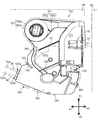
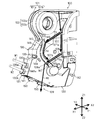
- FIG. 1 is a side view of a vehicle door lock device 100 provided on a vehicle door DR as viewed from the inside of the vehicle.
- FIG. 2 is a view showing the protection member 130 attached to the vehicle door lock device 100 in FIG. 1 with the second cover portion 141 in the deployed position.
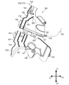
- FIG. 3 is a view showing the protective member 130 in FIG. 2 in a state before being attached to the vehicle door lock device 100.
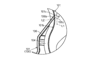
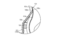
- FIG. 4 is an enlarged view of a region A in FIG.
- FIG. 5 is a view showing a modified example of the extended tip portion 136b of the standing wall 136 in FIG.
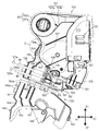
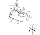
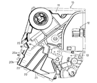
- FIG. 6 is a perspective view of the vehicle door lock device 100 in FIG.
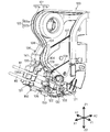
- FIG. 7 is a perspective view of the second cover portion 141 of the protection member 130 in FIG. 1 as viewed obliquely from the front of the vehicle.
- FIG. 8 is a perspective view of the vehicle door lock device 100 in FIG. 1 as viewed obliquely from the front of the vehicle.
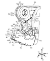
- FIG. 9 is a view showing a water guiding state in the vehicle door lock device 100 of FIG.
- FIG. 10 is a view showing a cross-sectional structure taken along the line BB of the vehicle door lock device 100 in FIG.
- FIG. 11 is a view showing a cross-sectional structure taken along the line CC of the vehicle door lock device 100 in FIG.
- FIG. 10 is a view showing a cross-sectional structure taken along the line BB of the vehicle door lock device 100 in FIG.
- FIG. 12 is a view showing a cross-sectional structure along the line DD of the vehicle door lock device 100 in FIG.
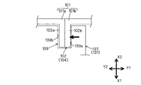
- FIG. 13 is a view schematically showing a locking recess 138 provided on the standing wall 136 of the first cover portion 131 locked to the convex portion 102 of the housing 101.
- FIG. 14 is a view schematically showing a locking recess 139 provided in the standing wall 137 of the first cover portion 131 locked to the convex portion 102 of the housing 101.
- FIG. FIG. 15 is a view schematically showing a locking recess 149 provided in the standing wall 148 of the second cover portion 141 locked to the convex portion 102 of the housing 101.
- FIG. 16 is a side view of the conventional vehicle door lock device 10 as viewed from the inside of the vehicle.
- a vehicle door lock device (hereinafter, also simply referred to as a “door lock device”) according to an embodiment of the present invention will be described with reference to a plurality of drawings.
- the arrow X1 and the arrow X2 indicate the front and the rear of the housing of the vehicle or the door lock device, and the left and right sides of the housing of the vehicle or the door lock are the arrows Y1 and Y2, respectively.
- the upper and lower sides of the housing of the vehicle or door lock are shown by arrows Z1 and Z2, respectively.
- the door lock device 100 is disposed in an area defined by a door outer panel outside the vehicle and a door inner panel inside the vehicle, which constitute the vehicle door DR.
- FIG. 1 shows a vehicle door on the right side of the rear seat as a typical example of the vehicle door DR.
- the housing 101 of the door lock device 100 is configured by joining an outer side component 101a and an inner side component 101b, both of which are made of a resin material, to each other.
- the housing 101 is provided with a protrusion 102 extending from the surface of the housing.
- a first rib 102a which typically extends along the edge of the outer component 101a
- a second rib 102b which extends along the edge of the inner component 101b
- the convex portion 102 serves as a water blocking function to block the flow of water from the outside of the vehicle to the inside of the vehicle.
- the housing 101 has a housing space for housing a plurality of components including the latch mechanism 110 and the lock mechanism 120. That is, the housing 101 is configured as a container that houses at least the latch mechanism 110 and the lock mechanism 120. In the housing 101, typically, a storage space for the latch mechanism 110 is provided on the vehicle rear side so as to face the striker ST fixed to the vehicle body BD, and the lock mechanism is on the vehicle front side of the storage space. A storage space for 120 is provided.
- This housing 101 corresponds to the "housing" of the present invention.
- a protective member 130 made of a resin material is attached.
- the protective member 130 is a member separate from the housing 101 and attached to the housing 101 to protect the housing 101. According to this protection member 130, the components of the door lock device 100 housed in the housing 101 are protected from water present outside the housing 101.
- This protection member 130 corresponds to the "protection member" of the present invention.
- the latch mechanism 110 is configured to be capable of holding the vehicle door DR in a closed state by engagement with the striker ST attached to the vehicle body BD.
- the lock mechanism 120 sets the latch mechanism 110 in an unlocked state in which engagement with the striker ST can be released or in a locked state in which engagement with the striker ST can not be released.
- the latch mechanism 110 and the lock mechanism 120 correspond to the "latch mechanism” and the "lock mechanism” of the present invention, respectively.
- the structure of the door lock device disclosed in JP 2013-167145 A is referred to.
- the lock mechanism 120 includes an inside open lever 121, an outside open lever (not shown), and an active lever 122.
- the inside open lever 121 is connected to an inside door handle 121a provided on the vehicle door DR via an inside open cable W1. For this reason, the inside open lever 121 is rotated by the operation of the inside door handle 121a.
- the outside open lever is connected to an outside door handle (not shown) provided on the vehicle door DR. For this reason, the outside open lever is rotated by the operation of the outside door handle.
- the active lever 122 is connected to a door lock knob 122a provided on the vehicle door DR via a locking cable W2. Therefore, the active lever 122 is rotated by the operation of the door lock knob 122a and the key cylinder (not shown).
- the inside open cable W ⁇ b> 1 and the locking cable W ⁇ b> 2 are both control cables in which the inner cable is movably inserted inside the hollow outer cable.
- the inside open cable W1 the inner cable exposed from the end of the outer cable is locked to the inside open lever 121.
- the locking cable W2 the inner cable exposed from the end of the outer cable is locked to the active lever 122.
- Both the inside open cable W1 and the locking cable W2 are bridged and held by the standing wall 106 provided on the housing 101 and the two standing walls 136 and 137 provided on the protective member 130. It is assembled to the housing 101.
- the inside open cable W1 is led out of the protection member 130 through an opening (cable outlet opening 130a in FIG. 1) provided in the protection member 130.
- the locking cable W2 is led out of the protective member 130 through an opening (a cable outlet opening 130b in FIG. 1) provided in the protective member 130.
- the protection member 130 includes a first cover portion 131 and a second cover portion 141.
- the first cover portion 131 includes the standing walls 136 and 137 described above.
- the first cover portion 131 is attached to the housing 101 before the cables W1 and W2 are erected on the erected walls 136 and 137.
- the first cover portion 131 is connected to the second cover portion 141 via the two hinge portions 150 and 150.
- the hinge portions 150 and 150 are thin portions provided between the first cover portion 131 and the second cover portion 141, both of which are made of a resin material. It is configured as a so-called "integral hinge" that produces a function. Therefore, the operator may rotate the second cover portion 141 with respect to the first cover portion 131 about the hinges 150 and 150 (hinge line 150 a) while holding the second cover portion 141. it can.
- the first cover portion 131, the second cover portion 141, and the hinge portions 150 and 150 are integrally molded of a resin material. Thereby, the structure of the protection member 130 can be simplified. Further, in the protection member 130, the protruding wall 136a protruding from the standing wall 136 of the first cover portion 131 and the two protruding walls 148a and 148a protruding respectively from the standing wall 148 of the second cover portion 141 The cable outlet openings 130a, 130b described above are enclosed. In this case, the cooperation of the protruding wall 136a and the protruding walls 148a and 148a can prevent the flow of water that is going to flow into the cable outlet openings 130a and 130b.
- the second cover portion 141 is set at a predetermined deployed position (the position shown in FIGS. 2 and 3) extending horizontally along the extension surface of the first cover portion 131. Ru.
- a predetermined deployed position the position shown in FIGS. 2 and 3
- Ru a state in which the second cover portion 141 is opened approximately 180 degrees with respect to the first cover portion 131 is formed.
- the second cover portion 141 is in the above-described deployed position.
- the second cover portion 141 is set to a closed position (the position shown in FIG. 1) which completely covers the erected walls 136 and 137 of the first cover portion 131 from the vehicle inner side. In the closed position, the inner surface of the cover of the first cover portion 131 and the inner surface of the cover of the second cover portion 141 face each other.
- the second cover portion 141 can be set at an arbitrary position between the deployed position and the closed position. For this reason, before the first cover portion 131 is attached to the housing 101 and the cables W1 and W2 are erected on the erected walls 136 and 137, the second cover portion 141 can be set at the deployed position. Thereafter, after the cables W1 and W2 are erected on the erected walls 136 and 137, the second cover portion 141 can be rotated about the hinge portions 150 and 150 from the deployed position to the closed position.
- the standing wall 136 is configured as an outer wall exposed to the outer surface of the protection member 130. Thus, the standing wall 136 blocks the flow of water from the front of the vehicle in the protective member 130.
- the standing wall 137 is configured as an inner wall provided inside the protective member 130. Thus, the standing wall 137 blocks the flow of water which intrudes into the protection member 130 from the front of the vehicle and further flows toward the housing 101. That is, the flow of water that is going to flow toward the housing 101 is blocked in two steps by the two standing walls 136, 137.
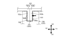
- the standing wall 136 is configured as a plate-like extending piece extending toward the mounting surface of the housing 101 (in FIG. 4, the mounting surface 101c of the in-vehicle component 101b) as shown in FIG.
- the extending tip portion 136b of the standing wall 136 has an inclined surface 136c which is inclined so that the plate thickness gradually decreases toward the tip, and the inclined surface 136c has a shape along the mounting surface 101c.
- the inclined surface 136c of the standing wall 136 is configured as an abutting surface that comes into surface contact with the mounting surface 101c.
- the inclined surface 136c of the standing wall 136 can be a flat surface following the flat surface, and the mounting surface 101c of the housing 101 is a curved surface.
- the inclined surface 136c of the upright wall 136 can be a curved surface that follows the curved surface. According to this surface contact structure, a high water sealing effect can be obtained between the standing wall 136 provided on the first cover portion 131 of the protective member 130 and the mounting surface of the housing 101.
- the contact area between the extending tip portion 136b and the mounting surface 101c is increased even if the plate thickness of the standing wall 136 is constant. It is advantageous to enhance the water sealing effect.
- the standing wall 136 extends along the second reference line L2 which forms a predetermined angle ⁇ with the first reference line L1 in a state where the protection member 130 is attached to the housing 101.
- the angle setting is made.
- the first reference line L1 is typically defined as a line extending in the vertical direction when the vehicle equipped with the door lock device is installed on a flat ground.
- the angle ⁇ is a value (typically within a range of 15 to 20 degrees) such that the second reference line L2 does not reach the position where the second reference line L2 extends in the horizontal direction, even when the vehicle on which the vehicle is mounted inclines Is preferably set to a value).
- the upright wall 136 can be made to have an acute angle with respect to the housing 101, and the water can flow down along the surface of the upright wall 136 regardless of the traveling condition of the mounted vehicle. As a result, it is possible to form a water pool in a portion where the inclined surface 136c of the upright wall 136 comes into surface contact with the mounting surface 101c and prevent water from infiltrating from the portion.
- the inclined surface 136c provided at the extending tip end portion 136b of the erected wall 136 in FIG. 5 is an abutting surface that abuts against the mounting surface 101c in a state of being pressed against the mounting surface 101c of the housing 101 and being bent and deformed. Is configured as.
- the standing wall 136 it is preferable to make the extending tip portion 136b thinner than other portions so that the inclined surface 136c is easily bent and deformed. Also in this case, as in the configuration shown in FIG.
- a high water sealing effect can be obtained between the upright wall 136 and the mounting surface of the housing 101 by a simple structure.
- the pressing force against the mounting surface 101c of the housing 101 is increased by the bending deformation of the inclined surface 136c of the protective member 130, which is advantageous for enhancing the water sealing effect.
- the contact area between the extending distal end portion 136b of the standing wall 136 and the mounting surface 101c can be increased.
- the first cover portion 131 of the protection member 130 is attached to the housing 101.
- the first cover portion 131 is a locking means capable of locking the first cover portion 131 to the housing 101 (locking pawl 132, locking recess (Locking slits) 138, 139) are provided.
- the locking claw 132 has a claw shape that can be engaged with an extension region 103 of the convex portion 102 of the housing 101 that extends toward the vehicle lower side (lower side of the housing 101) Z2.
- the locking recess 138 is provided on the standing wall 136 of the first cover portion 131, and engages with an extension region 104 of the convex portion 102 of the housing 101 that extends toward the vehicle front (the front of the housing 101) X1. It is configured as a possible recess.
- the locking recess 139 is provided on the standing wall 137 of the first cover portion 131, and is configured as a recess that can be engaged with the extension region 104 of the protrusion 102 of the housing 101.
- the locking means of the first cover portion 131 of the protective member 130 in a state where the first cover portion 131 is attached to the housing 101, as shown in FIG.
- the locking claws 132 engage with 103, and the locking recesses 138 and 139 engage with the extension regions 104 of the housing 101, respectively.
- FIG. 6 for convenience, the protection member 130 in a state in which the second cover portion 141 is removed is shown.
- the first cover portion 131 is configured to engage with the second cover portion 141 when the second cover portion 141 is set to the closed position.
- the first cover portion 131 is provided with an engagement protrusion 135 engageable with the opening (the opening 144 in FIG. 3) of the second cover portion 141.
- the engagement protrusion 135 has a structure so-called "snap-fit structure" which is fitted into the opening 144 by utilizing the elasticity of the material.
- locking means (locking claw 142, locking concave portion (locking slit) capable of locking the second cover portion 141 to the housing 101. 149) is provided.
- the protection member 130 is shown in a state in which the first cover portion 131 is removed.
- the locking claw 142 has a claw shape that can be engaged with a region (extension region 105 in FIG. 2) extending toward the vehicle rear (rear of the housing 101) X2 of the convex portion 102 of the housing 101.
- the locking recess 149 is provided on the standing wall 148 of the second cover portion 141, and engages with the extension region 104 of the convex portion 102 of the housing 101 similarly to the locking recesses 138 and 139 of the first cover portion 131. It is configured as a possible recess.
- the housing 101 (FIG. 2 in FIG. 2) is referred to.
- the locking claws 142 are engaged with the extension region 105), and the locking recess 149 is engaged with the extension region 104 of the housing 101.
- the engagement protrusion 135 of the first cover portion 131 is fitted into the opening 144 of the second cover portion 141.
- an interference wall 145 is formed by extending a convex portion protruding toward the left side of the vehicle (left side of the housing 101) Y1 continuously along the vehicle vertical direction Z1 and Z2 (vertical direction of the housing 101) ing.
- the opposing wall 146 is formed by extending a convex portion projecting toward the vehicle left direction (left direction of the housing 101) Y1 continuously along the vehicle longitudinal direction (longitudinal direction of the housing 101) X1, X2. ing.
- the water guiding slit 147 is formed at the boundary between the interference wall 145 and the facing wall 146.
- the door lock device 100 in order to prevent the components contained in the housing 101 from being frozen or rusted, a structure that prevents the entry of water into the opening formed in the protective member 130. Is required.
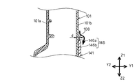
- the opening 144 of the second cover portion 141 is provided above the housing than the cable outlet openings 130 a and 130 b, and the water flowing down the housing surface of the housing 101 Is a site where you want to give priority to flood protection. Therefore, the door lock device 100 according to the present embodiment is provided with a water guiding structure in which at least the opening 144 is subjected to water immersion protection.
- This water guiding structure corresponds to the “water guiding structure” of the present invention, and functions to guide water so as to avoid the opening 144 formed in the protection member 130.
- this water guiding structure comprises two water guiding ribs 107, 108 spaced from each other in the vertical direction of the housing 101 on the housing surface of the housing 101 (the side of the inner component 101b); And an interference wall 145 provided on the second cover portion 141 of the protection member 130.
- the water guiding rib 107 is elongatedly provided along the front and rear directions X1 and X2 of the housing 101 on the side surface of the vehicle interior component 101b above the opening 144.
- the water guiding rib 107 functions to guide the water entering the vehicle door to a predetermined water guiding area 107a above the opening 144 along the upper surface of the rib.
- the water guiding rib 107 is a rib provided above the housing 101 than the water guiding rib 108, and corresponds to the "water guiding rib" and the "upper rib” of the present invention.
- the water guiding rib 108 is provided on the side surface of the in-vehicle component member 101 b at a lower side than the water guiding rib 107 so as to extend along the longitudinal direction X1, X2 of the housing 101.
- the water guide rib 108 functions to guide the water entering the vehicle door to a predetermined water guide area 108 a below the opening 144 along the upper surface of the rib.
- the water guide rib 108 is a rib provided below the housing 101 than the water guide rib 107, and corresponds to the "water guide rib" and the "lower rib” in the present invention.
- the interference wall 145 is interposed between the water guiding area 107a of the water guiding rib 107 and the opening 144, and between the water guiding area 108a of the water guiding rib 108 and the opening 144 in the vertical direction Z1,1 of the housing 101. It intervenes along Z2. Accordingly, the interference wall 145 functions to interfere with the flow of water from each of the water guiding regions 107 a, 108 a towards the opening 144. Therefore, the flow of water from each of the water guiding regions 107 a and 108 a to the opening 144 can be blocked by the interference wall 145 and disturbed, and water can not easily enter the opening 144.
- the interference wall 145 extends in an elongated shape to face both the water guiding rib 107 and the water guiding rib 108, and further guides the water guided to the water guiding area 107a to the merging area 107b. Is configured.
- the confluence area 107b is located on the upper surface of the water guide rib 108 below the opening section 144 and below the opening section 101, and is separated from the opening section 144 more than the water induction area 107a in the longitudinal direction X1 and X2 of the housing 101. doing. Therefore, the water guided to the merging area 107b by the water guiding rib 107 can be further merged with the water guided to the merging area 107b by the water guiding rib 108 while the water is further separated from the opening 144 by the interference wall 145. it can.
- the water guiding structure of the above configuration it is possible to form a guiding flow of water as shown in FIG. Specifically, the water that has entered the vehicle door flows in the direction indicated by the arrow f1 according to the gravity and then reaches the upper surface of the water guiding rib 107. Alternatively, the water that has entered the vehicle door flows in the direction indicated by the arrow f2 according to the gravity and then reaches the upper surface of the water guiding rib 108.
- the water flows along the upper surface of the rib in the direction indicated by the arrow f3 to be guided to the water guiding region 107a.
- the water flow toward the opening 144 and the interference wall 145 interfere with each other to change the flow direction of the water, and the direction indicated by the arrow f4 toward the merging region 107b along the interference wall 145 Induced to
- the interference wall 145 preferably has a curved shape so as to further guide the water guided to the water guiding area 107 a in the direction away from the opening 144.
- the water guided to the water guiding area 107a can be further moved away from the opening 144.
- the inundation preventing effect on the opening 144 can be further enhanced.
- the water guiding rib 108 is fitted into the water guiding slit 147.
- the water guide slit 147 has a slit width such that a gap is formed between it and the water guide rib 108. Therefore, the water guided in the direction indicated by the arrow f5 by the water guiding rib 108 merges with the water guided to the merging area 107b along the interference wall 145, and then the water guiding rib 108 and the water guiding slit 147 Are guided to the water guiding area 108a through the gap between them. Thereafter, the water guided to the water guiding area 108a flows down to the drainage area 109 which has less influence on water immersion in the direction indicated by the arrow f6 according to the gravity.
- the interference wall 145 of the second cover portion 141 has a tip portion 145a on the rear X2 side of the housing 101, and the tip portion 145a gradually decreases in thickness toward the rear X2 of the housing 101.
- the tip end portion 145 a of the interference wall 145 is configured to face the water guiding region 107 a of the water guiding rib 107. Therefore, according to this tapered shape, the water (see the arrow in FIG. 10) which has flowed to the tip end portion 145a of the interference wall 145 does not easily accumulate in the region 145b between the water guiding region 107a and the tip end portion 145a.
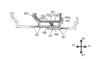
- the opposing wall 146 of the second cover portion 141 is disposed below the water guiding rib 108 and extends along the lower surface of the water guiding rib 108 in an elongated shape. Is preferred.
- the facing wall 146 corresponds to the "facing wall" in the present invention.
- the opposing wall 146 has a wall height with respect to the vertical height direction of the water guiding rib 108 below the vertical height d of the water guiding rib 108 in the proximity region 146a close to the rib lower surface and downward from the proximity region 146a
- the height of the water guiding rib 108 is set to be greater than the standing height d of the water guiding rib 108 in the clearance area 146 b which gradually decreases toward the separation area 146 b.
- This configuration can be realized typically by gradually increasing the thickness of the facing wall 146 from the proximity region 146a to the separation region 146b.
- the water (see the arrow in FIG. 11) that has flowed over the water guiding rib 108 to the vehicle lower side (lower side of the housing 101) Z2 flows along the opposing wall 146.
- the wall height of the proximity region 146a is relatively low in the facing wall 146, water is easily induced downward beyond the boundary between the rib lower surface of the water guiding rib 108 and the proximity region 146a of the facing wall 146 .
- the opposing wall 146 has a function of causing the water flowing out of the original guiding path of the water guiding rib 108 to flow smoothly down without entering the housing 101 side. It is preferable that the opposing wall 146 be configured to abut on the lower surface of the water guiding rib 108 in the proximity region 146a. In this case, entry of water from the boundary between the rib lower surface of the water guiding rib 108 and the proximity region 146a of the opposing wall 146 can be more reliably prevented.
- the protective member 130 having the above configuration sandwiches the housing 101 from the both sides by the first cover portion 131 and the second cover portion 141 in the vehicle left-right direction (left and right direction of the housing 101) Y1 and Y2. It is attached to 101 (see the arrow in FIG. 12).
- the first cover portion 131 is attached to the outside component member 101a of the housing 101
- the second cover portion 141 is attached to the inside component member 101b of the housing 101.
- the outer surface of the existing housing 101 has the attachment surface of each cover portion. It will be easier to As a result, water sealing performance effective to prevent water from entering the housing 101 from the boundary between the side surface of the housing 101 and the deposition surface of the protective member 130 can be obtained.
- the protective member 130 slides each of the first cover portion 131 and the second cover portion 141 in the vehicle left-right direction Y1, Y2 in accordance with the size of the housing 101 (hereinafter, also referred to as "width dimension”).
- has a structure that can be used hereinafter also referred to as “slide structure”
- the width dimension of the housing 101 changes due to the influence of the assembled state of the components accommodated in the housing 101, the adhesion state of the protective member 130 to the housing 101 is maintained.
- the shape of the protective member 130 can be made to follow the existing shape of the housing 101.
- the width dimension of the housing 101 changes, the phenomenon that the adhesion surface of the protection member 130 separates from the side surface of the housing 101, so-called "opening" does not occur, and the above water seal performance Can be maintained.
- the desired water sealing performance can be obtained without attaching a seal member such as a non-woven fabric to the boundary between the side surface of the housing 101 and the attachment surface of the protective member 130.
- the structure of 100 can be simplified.
- the protective member 130 changes only with respect to the dimensions in the vehicle left-right direction Y1 and Y2 due to the slide structure, the management of the tolerance of the door lock device 100 is facilitated.
- the protection wall 130 extending from the first cover portion 131 toward the second cover portion 141 and the The thickness direction (plate thickness direction) of the standing walls 136 and 148 in the overlapping area 151 on the front side of the vehicle, that is, the front and rear sides of the vehicle It has a structure (hereinafter, also referred to as an “overlap structure”) in which the directions abut against each other and partially overlap. According to this overlapping structure, an effect of preventing water from infiltrating from the boundary between the protective member 130 and the housing 101 at a portion on the vehicle front side of the protective member 130 can be obtained.
- the protective member 130 having the above configuration has a locking structure that is locked to the housing 101 by using the convex portion 102.
- the locking concave portion 138 of the standing wall 136 is hooked on the convex portion 102 (extension region 104) (see FIG. 13).
- the hooking recess 139 of the standing wall 137 is hooked and held on the housing 101 (see FIG. 14) by being hooked on the projection 102 (the extension area 104).
- the slit width dimensions of the locking recesses 138 and 139 are both configured to substantially match the width dimensions of the protrusion 102.
- the second cover portion 141 of the protection member 130 is engaged with the housing 101 by the locking recess 149 of the standing wall 148 being hooked on the protrusion 102 (the extension area 104). Locked and held.
- the slit width dimension of the locking recess 149 is configured to substantially match the width dimension of the protrusion 102.
- the first cover portion 131 and the second cover portion 141 of the protective member 130 are each locked to the housing 101 via the convex portion 102, so that the protective member 130 can be easily attached to the housing 101.
- the workability for mounting can be improved.
- the two locking recesses 138 and 139 are hooked on the convex portion 102, and the locking force is increased.
- the convex portion 102 of the housing 101 and the standing walls 136, 137, and 148 of the protective member 130 also serve as a locking means for locking the protective member 130 to the housing 101, a dedicated locking means is used. It is not necessary to provide it, and it can suppress that the external shape of the door lock apparatus 100 becomes large.
- the first cover portion 131 is in the vehicle right direction (right side of the housing 101) as shown by the arrows in FIGS.
- the second cover portion 141 is biased to the left of the vehicle (left of the housing 101) Y1 as shown by the arrow in FIG. That is, in a state where the protective member 130 is attached to the housing 101, that is, in a state where the first cover portion 131 and the second cover portion 141 are both hooked on the convex portion 102, the first cover portion 131 and the second cover portion 141 They are respectively urged to be separated from each other in the vehicle left-right direction Y1, Y2.
- one slit surface 138a of the two slit surfaces 138a and 138b of the locking recess 138 is pressed against the second rib 102b, and the two slit surfaces 139a of the locking recess 139 , 139b is pressed against the second rib 102b.
- one slit surface 149b of the two slit surfaces 149a and 149b of the locking recess 149 is pressed against the first rib 102a.
- two water guiding ribs 107 and 108 which are disposed apart from each other in the vertical direction of the housing 101 are used on the housing surface of the housing 101.
- more than two water guiding ribs can be used.
- the water guide rib 108 is abbreviate
- the interference wall 145 extends in an elongated manner so as to face the two water guiding ribs 107 and 108, and further induces the water guided to the water guiding area 107a.
- the interference wall 145 has a function to interfere with the flow of water from the water guiding region 107a to the opening 144. It is enough if you have at least. Therefore, in the present invention, a configuration in which the interference wall 145 faces only the water guiding rib 107 or a configuration in which the interference wall 145 linearly extends in the vertical direction of the vehicle can be adopted.
- the first cover portion 131, the second cover portion 141, and the hinge portion 150 are described as the protection member 130 integrally formed of a resin material, but these three components have separate structures. There may be, and at least one of the three components may be made of a metallic material.
- the essential structure of the door lock device 100 described above can be applied to each vehicle door of a vehicle.
- the essential structure of the vehicle door lock device 100 can be applied to left and right doors for the front seat of the vehicle, right and left doors for the rear seat of the vehicle, and a back door at the rear of the vehicle.
Landscapes
- Lock And Its Accessories (AREA)
Applications Claiming Priority (2)
| Application Number | Priority Date | Filing Date | Title |
|---|---|---|---|
| JP2014-023189 | 2014-02-10 | ||
| JP2014023189A JP6317592B2 (ja) | 2014-02-10 | 2014-02-10 | 車両用ドアロック装置 |
Publications (1)
| Publication Number | Publication Date |
|---|---|
| WO2015118916A1 true WO2015118916A1 (ja) | 2015-08-13 |
Family
ID=53777724
Family Applications (1)
| Application Number | Title | Priority Date | Filing Date |
|---|---|---|---|
| PCT/JP2015/050757 Ceased WO2015118916A1 (ja) | 2014-02-10 | 2015-01-14 | 車両用ドアロック装置 |
Country Status (2)
| Country | Link |
|---|---|
| JP (1) | JP6317592B2 (cg-RX-API-DMAC7.html) |
| WO (1) | WO2015118916A1 (cg-RX-API-DMAC7.html) |
Cited By (4)
| Publication number | Priority date | Publication date | Assignee | Title |
|---|---|---|---|---|
| CN110374425A (zh) * | 2019-07-26 | 2019-10-25 | 奇瑞汽车股份有限公司 | 汽车侧门锁防水结构 |
| US20220074239A1 (en) * | 2020-09-10 | 2022-03-10 | Mitsui Kinzoku Act Corporation | Waterproof structure for door latch device |
| US11542728B2 (en) * | 2018-10-02 | 2023-01-03 | Aisin Corporation | Vehicle door lock device |
| US20230193665A1 (en) * | 2020-07-15 | 2023-06-22 | Kiekert Aktiengesellschaft | Motor vehicle lock |
Families Citing this family (1)
| Publication number | Priority date | Publication date | Assignee | Title |
|---|---|---|---|---|
| CN111577008B (zh) * | 2020-05-07 | 2021-04-27 | 重庆特斯联智慧科技股份有限公司 | 一种物联网智慧门锁 |
Citations (1)
| Publication number | Priority date | Publication date | Assignee | Title |
|---|---|---|---|---|
| JP2010037781A (ja) * | 2008-08-04 | 2010-02-18 | Shiroki Corp | ドアロック装置 |
Family Cites Families (6)
| Publication number | Priority date | Publication date | Assignee | Title |
|---|---|---|---|---|
| JPH09105252A (ja) * | 1995-10-12 | 1997-04-22 | Central Motor Co Ltd | キーシリンダー周りの排水構造 |
| JP5070649B2 (ja) * | 2010-03-19 | 2012-11-14 | 三井金属アクト株式会社 | 車両用ドアラッチ装置 |
| US8677692B2 (en) * | 2011-01-25 | 2014-03-25 | Honda Motor Co., Ltd. | Door latch cover |
| JP5578734B2 (ja) * | 2011-10-11 | 2014-08-27 | アイシン機工株式会社 | 車両用ドアロック装置 |
| JP5495163B2 (ja) * | 2011-03-02 | 2014-05-21 | 三井金属アクト株式会社 | 自動車用ドアロック装置 |
| JP5743797B2 (ja) * | 2011-08-09 | 2015-07-01 | 三井金属アクト株式会社 | 車両用ドアロック装置 |
-
2014
- 2014-02-10 JP JP2014023189A patent/JP6317592B2/ja active Active
-
2015
- 2015-01-14 WO PCT/JP2015/050757 patent/WO2015118916A1/ja not_active Ceased
Patent Citations (1)
| Publication number | Priority date | Publication date | Assignee | Title |
|---|---|---|---|---|
| JP2010037781A (ja) * | 2008-08-04 | 2010-02-18 | Shiroki Corp | ドアロック装置 |
Cited By (6)
| Publication number | Priority date | Publication date | Assignee | Title |
|---|---|---|---|---|
| US11542728B2 (en) * | 2018-10-02 | 2023-01-03 | Aisin Corporation | Vehicle door lock device |
| CN110374425A (zh) * | 2019-07-26 | 2019-10-25 | 奇瑞汽车股份有限公司 | 汽车侧门锁防水结构 |
| US20230193665A1 (en) * | 2020-07-15 | 2023-06-22 | Kiekert Aktiengesellschaft | Motor vehicle lock |
| US12291898B2 (en) * | 2020-07-15 | 2025-05-06 | Kiekert Ag | Motor vehicle lock |
| US20220074239A1 (en) * | 2020-09-10 | 2022-03-10 | Mitsui Kinzoku Act Corporation | Waterproof structure for door latch device |
| US11898381B2 (en) * | 2020-09-10 | 2024-02-13 | Mitsui Kinzoku Act Corporation | Waterproof structure for door latch device |
Also Published As
| Publication number | Publication date |
|---|---|
| JP6317592B2 (ja) | 2018-04-25 |
| JP2015148128A (ja) | 2015-08-20 |
Similar Documents
| Publication | Publication Date | Title |
|---|---|---|
| CN102460875B (zh) | 防水盒 | |
| WO2015118916A1 (ja) | 車両用ドアロック装置 | |
| JP5433313B2 (ja) | 防水ボックス | |
| CN102460874B (zh) | 防水盒 | |
| CN107429729B (zh) | 线缆连接机构 | |
| JP6404099B2 (ja) | ドアロック装置 | |
| US9413151B2 (en) | Electrical junction box | |
| JP6187014B2 (ja) | 車両用ドアロック装置 | |
| JP5193821B2 (ja) | 電気接続箱のカバー閉止構造 | |
| US20120186159A1 (en) | Door latch cover | |
| WO2015019896A1 (ja) | 車両用ドアロック装置 | |
| JP7188292B2 (ja) | ワイヤハーネス用プロテクタ | |
| JP2012076607A (ja) | 充電ポート用カバーの配設構造 | |
| JP6911736B2 (ja) | 車両用給油部構造 | |
| JP6298310B2 (ja) | 車両用ドアロック装置 | |
| JP6298311B2 (ja) | 車両用ドアロック装置 | |
| KR101882745B1 (ko) | 후드래치 장치 | |
| JP4558545B2 (ja) | 自動車の無中間柱型隣接ドアのシール構造 | |
| CN112821307A (zh) | 液体排出结构 | |
| JP6156139B2 (ja) | トランクリッドヒンジ構造 | |
| JP6280708B2 (ja) | 車両用内装材 | |
| JP6156138B2 (ja) | トランクリッドヒンジ構造 | |
| WO2020189747A1 (ja) | 上部キャップおよびディビジョンバー取付構造 | |
| JP5800225B2 (ja) | リアドア | |
| KR101558779B1 (ko) | 자동차용 도어 열림 방지를 위한 케이블 블로킹 장치 |
Legal Events
| Date | Code | Title | Description |
|---|---|---|---|
| 121 | Ep: the epo has been informed by wipo that ep was designated in this application |
Ref document number: 15745799 Country of ref document: EP Kind code of ref document: A1 |
|
| NENP | Non-entry into the national phase |
Ref country code: DE |
|
| WWE | Wipo information: entry into national phase |
Ref document number: IDP00201606008 Country of ref document: ID |
|
| 122 | Ep: pct application non-entry in european phase |
Ref document number: 15745799 Country of ref document: EP Kind code of ref document: A1 |