WO2015118916A1 - Door lock device for vehicle - Google Patents
Door lock device for vehicle Download PDFInfo
- Publication number
- WO2015118916A1 WO2015118916A1 PCT/JP2015/050757 JP2015050757W WO2015118916A1 WO 2015118916 A1 WO2015118916 A1 WO 2015118916A1 JP 2015050757 W JP2015050757 W JP 2015050757W WO 2015118916 A1 WO2015118916 A1 WO 2015118916A1
- Authority
- WO
- WIPO (PCT)
- Prior art keywords
- housing
- water
- rib
- water guiding
- door lock
- Prior art date
Links
Images


Classifications
-
- E—FIXED CONSTRUCTIONS
- E05—LOCKS; KEYS; WINDOW OR DOOR FITTINGS; SAFES
- E05B—LOCKS; ACCESSORIES THEREFOR; HANDCUFFS
- E05B77/00—Vehicle locks characterised by special functions or purposes
- E05B77/34—Protection against weather or dirt, e.g. against water ingress
-
- E—FIXED CONSTRUCTIONS
- E05—LOCKS; KEYS; WINDOW OR DOOR FITTINGS; SAFES
- E05B—LOCKS; ACCESSORIES THEREFOR; HANDCUFFS
- E05B85/00—Details of vehicle locks not provided for in groups E05B77/00 - E05B83/00
- E05B85/02—Lock casings
Definitions
- the present invention relates to a door lock device for a vehicle provided in a vehicle.
- Japanese Patent Application No. 2013-166017 discloses a vehicle door lock device (hereinafter, also simply referred to as a “door lock device”) to which the present applicant previously filed.
- the door lock device 10 shown in FIG. 16 includes a housing 11 that accommodates components such as the latch mechanism 12 and the lock mechanism 13, and a protection member 20 attached to the housing 11.
- the protective member 20 is provided with ribs 22 and 23 on the outer surface of the cover 21 inside the vehicle, and by means of the cooperation of the ribs 22 and 23 and the rib 14 provided on the outer surface of the housing 11, water immersion protection is achieved. It has a water guiding structure that guides the water so that the water does not flow into the desired area.
- the opening formed in the protective member 20 (cable outlet 20a for leading out the inside open cable W1 and cable outlet 20b for leading out the locking cable W2)
- the opening formed in the protective member 20 By guiding the water from the upper area to the lower area, it is possible to prevent the water from flowing into the opening.
- One of the objects of the present invention is to provide an effective technique for enhancing the effect of preventing water immersion on an opening formed in a protective member in a vehicle door lock device having the protective member attached to a housing. .
- a vehicle door lock device includes a latch mechanism, a lock mechanism, a housing, a protection member, and a water guiding structure.
- the latch mechanism is configured to be capable of holding the vehicle door closed by engagement with a striker attached to the vehicle body.
- the lock mechanism functions to set the latch mechanism in an unlocked state configured to be releasable to engage with the striker or a lock state configured to be unreleasable to engage the striker.
- the housing is configured as a housing that accommodates at least the latch mechanism and the lock mechanism.
- the protective member is attached to the housing to protect the housing. This protection member particularly serves to protect the elements contained in the housing from the water present outside the housing.
- the water guiding structure functions to guide water so as to avoid the opening formed in the protection member.
- the water guiding structure includes water guiding ribs and an interference wall.
- the water guide rib is elongatedly provided along the front-rear direction of the housing on the outer surface of the housing in order to guide the water entering the vehicle door to a predetermined water guide region.
- the interference wall is interposed along the vertical direction of the housing between the water guide rib and the opening of the protective member to interfere with the flow of water from the water guide region to the opening.
- the flow of water from the water guiding region to the opening can be blocked by the interference wall and disturbed, and water can not easily enter the opening.
- the interference wall preferably further guides the water guided to the water guiding area in a direction away from the opening.
- the water guided to the water guiding region can be further moved away from the opening, and the water immersion preventing effect on the opening of the protective member can be further enhanced.
- the water guiding rib preferably includes an upper rib and a lower rib which are disposed apart from each other in the vertical direction of the housing on the outer surface of the housing.
- the water guiding ribs may be configured to include further ribs in addition to the upper and lower ribs.
- the interference wall extends longitudinally along the vertical direction of the housing while facing both the upper rib and the lower rib, and the water guided by the upper rib is further located below the housing than the opening. It is preferable to perform the function of guiding to the merging area and merging with the water induced by the lower rib.
- the protection member preferably includes an opposite wall disposed opposite along the lower surface of the water guiding rib.
- the opposing wall is a separation region in which the wall height with respect to the vertical height direction of the water guiding rib is lower than the vertical height of the water guiding rib in the close area close to the rib lower surface and spaced downward from the close area. It is preferable to be configured to exceed the standing height of the water guiding rib in the gradually decreasing separation area as it goes. In this case, the water flowing down the housing beyond the water guide rib flows along the opposing wall.
- the wall height of the proximity region is relatively low in the facing wall, water is easily induced downward beyond the boundary between the lower surface of the rib of the water guiding rib and the proximity region of the opposite wall. As a result, it is possible to prevent the entry of water from the boundary between the rib lower surface of the water guiding rib and the proximity region of the opposing wall. That is, the opposing wall has a function of causing the water flowing out of the inherent guiding path of the water guiding rib to flow smoothly down without entering the housing side.
- the present invention in the vehicle door lock device in which the protective member is attached to the housing, it is possible to enhance the effect of preventing water immersion to the opening formed in the protective member.
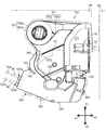
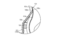
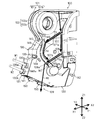
- FIG. 1 is a side view of a vehicle door lock device 100 provided on a vehicle door DR as viewed from the inside of the vehicle.
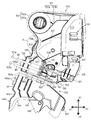
- FIG. 2 is a view showing the protection member 130 attached to the vehicle door lock device 100 in FIG. 1 with the second cover portion 141 in the deployed position.
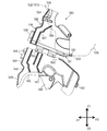
- FIG. 3 is a view showing the protective member 130 in FIG. 2 in a state before being attached to the vehicle door lock device 100.
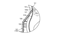
- FIG. 4 is an enlarged view of a region A in FIG.
- FIG. 5 is a view showing a modified example of the extended tip portion 136b of the standing wall 136 in FIG.
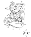
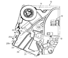
- FIG. 6 is a perspective view of the vehicle door lock device 100 in FIG.
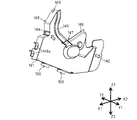
- FIG. 7 is a perspective view of the second cover portion 141 of the protection member 130 in FIG. 1 as viewed obliquely from the front of the vehicle.
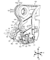
- FIG. 8 is a perspective view of the vehicle door lock device 100 in FIG. 1 as viewed obliquely from the front of the vehicle.
- FIG. 9 is a view showing a water guiding state in the vehicle door lock device 100 of FIG.
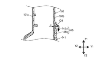
- FIG. 10 is a view showing a cross-sectional structure taken along the line BB of the vehicle door lock device 100 in FIG.
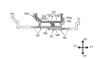
- FIG. 11 is a view showing a cross-sectional structure taken along the line CC of the vehicle door lock device 100 in FIG.
- FIG. 10 is a view showing a cross-sectional structure taken along the line BB of the vehicle door lock device 100 in FIG.
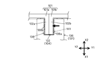
- FIG. 12 is a view showing a cross-sectional structure along the line DD of the vehicle door lock device 100 in FIG.
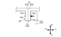
- FIG. 13 is a view schematically showing a locking recess 138 provided on the standing wall 136 of the first cover portion 131 locked to the convex portion 102 of the housing 101.
- FIG. 14 is a view schematically showing a locking recess 139 provided in the standing wall 137 of the first cover portion 131 locked to the convex portion 102 of the housing 101.
- FIG. FIG. 15 is a view schematically showing a locking recess 149 provided in the standing wall 148 of the second cover portion 141 locked to the convex portion 102 of the housing 101.
- FIG. 16 is a side view of the conventional vehicle door lock device 10 as viewed from the inside of the vehicle.
- a vehicle door lock device (hereinafter, also simply referred to as a “door lock device”) according to an embodiment of the present invention will be described with reference to a plurality of drawings.
- the arrow X1 and the arrow X2 indicate the front and the rear of the housing of the vehicle or the door lock device, and the left and right sides of the housing of the vehicle or the door lock are the arrows Y1 and Y2, respectively.
- the upper and lower sides of the housing of the vehicle or door lock are shown by arrows Z1 and Z2, respectively.
- the door lock device 100 is disposed in an area defined by a door outer panel outside the vehicle and a door inner panel inside the vehicle, which constitute the vehicle door DR.
- FIG. 1 shows a vehicle door on the right side of the rear seat as a typical example of the vehicle door DR.
- the housing 101 of the door lock device 100 is configured by joining an outer side component 101a and an inner side component 101b, both of which are made of a resin material, to each other.
- the housing 101 is provided with a protrusion 102 extending from the surface of the housing.
- a first rib 102a which typically extends along the edge of the outer component 101a
- a second rib 102b which extends along the edge of the inner component 101b
- the convex portion 102 serves as a water blocking function to block the flow of water from the outside of the vehicle to the inside of the vehicle.
- the housing 101 has a housing space for housing a plurality of components including the latch mechanism 110 and the lock mechanism 120. That is, the housing 101 is configured as a container that houses at least the latch mechanism 110 and the lock mechanism 120. In the housing 101, typically, a storage space for the latch mechanism 110 is provided on the vehicle rear side so as to face the striker ST fixed to the vehicle body BD, and the lock mechanism is on the vehicle front side of the storage space. A storage space for 120 is provided.
- This housing 101 corresponds to the "housing" of the present invention.
- a protective member 130 made of a resin material is attached.
- the protective member 130 is a member separate from the housing 101 and attached to the housing 101 to protect the housing 101. According to this protection member 130, the components of the door lock device 100 housed in the housing 101 are protected from water present outside the housing 101.
- This protection member 130 corresponds to the "protection member" of the present invention.
- the latch mechanism 110 is configured to be capable of holding the vehicle door DR in a closed state by engagement with the striker ST attached to the vehicle body BD.
- the lock mechanism 120 sets the latch mechanism 110 in an unlocked state in which engagement with the striker ST can be released or in a locked state in which engagement with the striker ST can not be released.
- the latch mechanism 110 and the lock mechanism 120 correspond to the "latch mechanism” and the "lock mechanism” of the present invention, respectively.
- the structure of the door lock device disclosed in JP 2013-167145 A is referred to.
- the lock mechanism 120 includes an inside open lever 121, an outside open lever (not shown), and an active lever 122.
- the inside open lever 121 is connected to an inside door handle 121a provided on the vehicle door DR via an inside open cable W1. For this reason, the inside open lever 121 is rotated by the operation of the inside door handle 121a.
- the outside open lever is connected to an outside door handle (not shown) provided on the vehicle door DR. For this reason, the outside open lever is rotated by the operation of the outside door handle.
- the active lever 122 is connected to a door lock knob 122a provided on the vehicle door DR via a locking cable W2. Therefore, the active lever 122 is rotated by the operation of the door lock knob 122a and the key cylinder (not shown).
- the inside open cable W ⁇ b> 1 and the locking cable W ⁇ b> 2 are both control cables in which the inner cable is movably inserted inside the hollow outer cable.
- the inside open cable W1 the inner cable exposed from the end of the outer cable is locked to the inside open lever 121.
- the locking cable W2 the inner cable exposed from the end of the outer cable is locked to the active lever 122.
- Both the inside open cable W1 and the locking cable W2 are bridged and held by the standing wall 106 provided on the housing 101 and the two standing walls 136 and 137 provided on the protective member 130. It is assembled to the housing 101.
- the inside open cable W1 is led out of the protection member 130 through an opening (cable outlet opening 130a in FIG. 1) provided in the protection member 130.
- the locking cable W2 is led out of the protective member 130 through an opening (a cable outlet opening 130b in FIG. 1) provided in the protective member 130.
- the protection member 130 includes a first cover portion 131 and a second cover portion 141.
- the first cover portion 131 includes the standing walls 136 and 137 described above.
- the first cover portion 131 is attached to the housing 101 before the cables W1 and W2 are erected on the erected walls 136 and 137.
- the first cover portion 131 is connected to the second cover portion 141 via the two hinge portions 150 and 150.
- the hinge portions 150 and 150 are thin portions provided between the first cover portion 131 and the second cover portion 141, both of which are made of a resin material. It is configured as a so-called "integral hinge" that produces a function. Therefore, the operator may rotate the second cover portion 141 with respect to the first cover portion 131 about the hinges 150 and 150 (hinge line 150 a) while holding the second cover portion 141. it can.
- the first cover portion 131, the second cover portion 141, and the hinge portions 150 and 150 are integrally molded of a resin material. Thereby, the structure of the protection member 130 can be simplified. Further, in the protection member 130, the protruding wall 136a protruding from the standing wall 136 of the first cover portion 131 and the two protruding walls 148a and 148a protruding respectively from the standing wall 148 of the second cover portion 141 The cable outlet openings 130a, 130b described above are enclosed. In this case, the cooperation of the protruding wall 136a and the protruding walls 148a and 148a can prevent the flow of water that is going to flow into the cable outlet openings 130a and 130b.
- the second cover portion 141 is set at a predetermined deployed position (the position shown in FIGS. 2 and 3) extending horizontally along the extension surface of the first cover portion 131. Ru.
- a predetermined deployed position the position shown in FIGS. 2 and 3
- Ru a state in which the second cover portion 141 is opened approximately 180 degrees with respect to the first cover portion 131 is formed.
- the second cover portion 141 is in the above-described deployed position.
- the second cover portion 141 is set to a closed position (the position shown in FIG. 1) which completely covers the erected walls 136 and 137 of the first cover portion 131 from the vehicle inner side. In the closed position, the inner surface of the cover of the first cover portion 131 and the inner surface of the cover of the second cover portion 141 face each other.
- the second cover portion 141 can be set at an arbitrary position between the deployed position and the closed position. For this reason, before the first cover portion 131 is attached to the housing 101 and the cables W1 and W2 are erected on the erected walls 136 and 137, the second cover portion 141 can be set at the deployed position. Thereafter, after the cables W1 and W2 are erected on the erected walls 136 and 137, the second cover portion 141 can be rotated about the hinge portions 150 and 150 from the deployed position to the closed position.
- the standing wall 136 is configured as an outer wall exposed to the outer surface of the protection member 130. Thus, the standing wall 136 blocks the flow of water from the front of the vehicle in the protective member 130.
- the standing wall 137 is configured as an inner wall provided inside the protective member 130. Thus, the standing wall 137 blocks the flow of water which intrudes into the protection member 130 from the front of the vehicle and further flows toward the housing 101. That is, the flow of water that is going to flow toward the housing 101 is blocked in two steps by the two standing walls 136, 137.
- the standing wall 136 is configured as a plate-like extending piece extending toward the mounting surface of the housing 101 (in FIG. 4, the mounting surface 101c of the in-vehicle component 101b) as shown in FIG.
- the extending tip portion 136b of the standing wall 136 has an inclined surface 136c which is inclined so that the plate thickness gradually decreases toward the tip, and the inclined surface 136c has a shape along the mounting surface 101c.
- the inclined surface 136c of the standing wall 136 is configured as an abutting surface that comes into surface contact with the mounting surface 101c.
- the inclined surface 136c of the standing wall 136 can be a flat surface following the flat surface, and the mounting surface 101c of the housing 101 is a curved surface.
- the inclined surface 136c of the upright wall 136 can be a curved surface that follows the curved surface. According to this surface contact structure, a high water sealing effect can be obtained between the standing wall 136 provided on the first cover portion 131 of the protective member 130 and the mounting surface of the housing 101.
- the contact area between the extending tip portion 136b and the mounting surface 101c is increased even if the plate thickness of the standing wall 136 is constant. It is advantageous to enhance the water sealing effect.
- the standing wall 136 extends along the second reference line L2 which forms a predetermined angle ⁇ with the first reference line L1 in a state where the protection member 130 is attached to the housing 101.
- the angle setting is made.
- the first reference line L1 is typically defined as a line extending in the vertical direction when the vehicle equipped with the door lock device is installed on a flat ground.
- the angle ⁇ is a value (typically within a range of 15 to 20 degrees) such that the second reference line L2 does not reach the position where the second reference line L2 extends in the horizontal direction, even when the vehicle on which the vehicle is mounted inclines Is preferably set to a value).
- the upright wall 136 can be made to have an acute angle with respect to the housing 101, and the water can flow down along the surface of the upright wall 136 regardless of the traveling condition of the mounted vehicle. As a result, it is possible to form a water pool in a portion where the inclined surface 136c of the upright wall 136 comes into surface contact with the mounting surface 101c and prevent water from infiltrating from the portion.
- the inclined surface 136c provided at the extending tip end portion 136b of the erected wall 136 in FIG. 5 is an abutting surface that abuts against the mounting surface 101c in a state of being pressed against the mounting surface 101c of the housing 101 and being bent and deformed. Is configured as.
- the standing wall 136 it is preferable to make the extending tip portion 136b thinner than other portions so that the inclined surface 136c is easily bent and deformed. Also in this case, as in the configuration shown in FIG.
- a high water sealing effect can be obtained between the upright wall 136 and the mounting surface of the housing 101 by a simple structure.
- the pressing force against the mounting surface 101c of the housing 101 is increased by the bending deformation of the inclined surface 136c of the protective member 130, which is advantageous for enhancing the water sealing effect.
- the contact area between the extending distal end portion 136b of the standing wall 136 and the mounting surface 101c can be increased.
- the first cover portion 131 of the protection member 130 is attached to the housing 101.
- the first cover portion 131 is a locking means capable of locking the first cover portion 131 to the housing 101 (locking pawl 132, locking recess (Locking slits) 138, 139) are provided.
- the locking claw 132 has a claw shape that can be engaged with an extension region 103 of the convex portion 102 of the housing 101 that extends toward the vehicle lower side (lower side of the housing 101) Z2.
- the locking recess 138 is provided on the standing wall 136 of the first cover portion 131, and engages with an extension region 104 of the convex portion 102 of the housing 101 that extends toward the vehicle front (the front of the housing 101) X1. It is configured as a possible recess.
- the locking recess 139 is provided on the standing wall 137 of the first cover portion 131, and is configured as a recess that can be engaged with the extension region 104 of the protrusion 102 of the housing 101.
- the locking means of the first cover portion 131 of the protective member 130 in a state where the first cover portion 131 is attached to the housing 101, as shown in FIG.
- the locking claws 132 engage with 103, and the locking recesses 138 and 139 engage with the extension regions 104 of the housing 101, respectively.
- FIG. 6 for convenience, the protection member 130 in a state in which the second cover portion 141 is removed is shown.
- the first cover portion 131 is configured to engage with the second cover portion 141 when the second cover portion 141 is set to the closed position.
- the first cover portion 131 is provided with an engagement protrusion 135 engageable with the opening (the opening 144 in FIG. 3) of the second cover portion 141.
- the engagement protrusion 135 has a structure so-called "snap-fit structure" which is fitted into the opening 144 by utilizing the elasticity of the material.
- locking means (locking claw 142, locking concave portion (locking slit) capable of locking the second cover portion 141 to the housing 101. 149) is provided.
- the protection member 130 is shown in a state in which the first cover portion 131 is removed.
- the locking claw 142 has a claw shape that can be engaged with a region (extension region 105 in FIG. 2) extending toward the vehicle rear (rear of the housing 101) X2 of the convex portion 102 of the housing 101.
- the locking recess 149 is provided on the standing wall 148 of the second cover portion 141, and engages with the extension region 104 of the convex portion 102 of the housing 101 similarly to the locking recesses 138 and 139 of the first cover portion 131. It is configured as a possible recess.
- the housing 101 (FIG. 2 in FIG. 2) is referred to.
- the locking claws 142 are engaged with the extension region 105), and the locking recess 149 is engaged with the extension region 104 of the housing 101.
- the engagement protrusion 135 of the first cover portion 131 is fitted into the opening 144 of the second cover portion 141.
- an interference wall 145 is formed by extending a convex portion protruding toward the left side of the vehicle (left side of the housing 101) Y1 continuously along the vehicle vertical direction Z1 and Z2 (vertical direction of the housing 101) ing.
- the opposing wall 146 is formed by extending a convex portion projecting toward the vehicle left direction (left direction of the housing 101) Y1 continuously along the vehicle longitudinal direction (longitudinal direction of the housing 101) X1, X2. ing.
- the water guiding slit 147 is formed at the boundary between the interference wall 145 and the facing wall 146.
- the door lock device 100 in order to prevent the components contained in the housing 101 from being frozen or rusted, a structure that prevents the entry of water into the opening formed in the protective member 130. Is required.
- the opening 144 of the second cover portion 141 is provided above the housing than the cable outlet openings 130 a and 130 b, and the water flowing down the housing surface of the housing 101 Is a site where you want to give priority to flood protection. Therefore, the door lock device 100 according to the present embodiment is provided with a water guiding structure in which at least the opening 144 is subjected to water immersion protection.
- This water guiding structure corresponds to the “water guiding structure” of the present invention, and functions to guide water so as to avoid the opening 144 formed in the protection member 130.
- this water guiding structure comprises two water guiding ribs 107, 108 spaced from each other in the vertical direction of the housing 101 on the housing surface of the housing 101 (the side of the inner component 101b); And an interference wall 145 provided on the second cover portion 141 of the protection member 130.
- the water guiding rib 107 is elongatedly provided along the front and rear directions X1 and X2 of the housing 101 on the side surface of the vehicle interior component 101b above the opening 144.
- the water guiding rib 107 functions to guide the water entering the vehicle door to a predetermined water guiding area 107a above the opening 144 along the upper surface of the rib.
- the water guiding rib 107 is a rib provided above the housing 101 than the water guiding rib 108, and corresponds to the "water guiding rib" and the "upper rib” of the present invention.
- the water guiding rib 108 is provided on the side surface of the in-vehicle component member 101 b at a lower side than the water guiding rib 107 so as to extend along the longitudinal direction X1, X2 of the housing 101.
- the water guide rib 108 functions to guide the water entering the vehicle door to a predetermined water guide area 108 a below the opening 144 along the upper surface of the rib.
- the water guide rib 108 is a rib provided below the housing 101 than the water guide rib 107, and corresponds to the "water guide rib" and the "lower rib” in the present invention.
- the interference wall 145 is interposed between the water guiding area 107a of the water guiding rib 107 and the opening 144, and between the water guiding area 108a of the water guiding rib 108 and the opening 144 in the vertical direction Z1,1 of the housing 101. It intervenes along Z2. Accordingly, the interference wall 145 functions to interfere with the flow of water from each of the water guiding regions 107 a, 108 a towards the opening 144. Therefore, the flow of water from each of the water guiding regions 107 a and 108 a to the opening 144 can be blocked by the interference wall 145 and disturbed, and water can not easily enter the opening 144.
- the interference wall 145 extends in an elongated shape to face both the water guiding rib 107 and the water guiding rib 108, and further guides the water guided to the water guiding area 107a to the merging area 107b. Is configured.
- the confluence area 107b is located on the upper surface of the water guide rib 108 below the opening section 144 and below the opening section 101, and is separated from the opening section 144 more than the water induction area 107a in the longitudinal direction X1 and X2 of the housing 101. doing. Therefore, the water guided to the merging area 107b by the water guiding rib 107 can be further merged with the water guided to the merging area 107b by the water guiding rib 108 while the water is further separated from the opening 144 by the interference wall 145. it can.
- the water guiding structure of the above configuration it is possible to form a guiding flow of water as shown in FIG. Specifically, the water that has entered the vehicle door flows in the direction indicated by the arrow f1 according to the gravity and then reaches the upper surface of the water guiding rib 107. Alternatively, the water that has entered the vehicle door flows in the direction indicated by the arrow f2 according to the gravity and then reaches the upper surface of the water guiding rib 108.
- the water flows along the upper surface of the rib in the direction indicated by the arrow f3 to be guided to the water guiding region 107a.
- the water flow toward the opening 144 and the interference wall 145 interfere with each other to change the flow direction of the water, and the direction indicated by the arrow f4 toward the merging region 107b along the interference wall 145 Induced to
- the interference wall 145 preferably has a curved shape so as to further guide the water guided to the water guiding area 107 a in the direction away from the opening 144.
- the water guided to the water guiding area 107a can be further moved away from the opening 144.
- the inundation preventing effect on the opening 144 can be further enhanced.
- the water guiding rib 108 is fitted into the water guiding slit 147.
- the water guide slit 147 has a slit width such that a gap is formed between it and the water guide rib 108. Therefore, the water guided in the direction indicated by the arrow f5 by the water guiding rib 108 merges with the water guided to the merging area 107b along the interference wall 145, and then the water guiding rib 108 and the water guiding slit 147 Are guided to the water guiding area 108a through the gap between them. Thereafter, the water guided to the water guiding area 108a flows down to the drainage area 109 which has less influence on water immersion in the direction indicated by the arrow f6 according to the gravity.
- the interference wall 145 of the second cover portion 141 has a tip portion 145a on the rear X2 side of the housing 101, and the tip portion 145a gradually decreases in thickness toward the rear X2 of the housing 101.
- the tip end portion 145 a of the interference wall 145 is configured to face the water guiding region 107 a of the water guiding rib 107. Therefore, according to this tapered shape, the water (see the arrow in FIG. 10) which has flowed to the tip end portion 145a of the interference wall 145 does not easily accumulate in the region 145b between the water guiding region 107a and the tip end portion 145a.
- the opposing wall 146 of the second cover portion 141 is disposed below the water guiding rib 108 and extends along the lower surface of the water guiding rib 108 in an elongated shape. Is preferred.
- the facing wall 146 corresponds to the "facing wall" in the present invention.
- the opposing wall 146 has a wall height with respect to the vertical height direction of the water guiding rib 108 below the vertical height d of the water guiding rib 108 in the proximity region 146a close to the rib lower surface and downward from the proximity region 146a
- the height of the water guiding rib 108 is set to be greater than the standing height d of the water guiding rib 108 in the clearance area 146 b which gradually decreases toward the separation area 146 b.
- This configuration can be realized typically by gradually increasing the thickness of the facing wall 146 from the proximity region 146a to the separation region 146b.
- the water (see the arrow in FIG. 11) that has flowed over the water guiding rib 108 to the vehicle lower side (lower side of the housing 101) Z2 flows along the opposing wall 146.
- the wall height of the proximity region 146a is relatively low in the facing wall 146, water is easily induced downward beyond the boundary between the rib lower surface of the water guiding rib 108 and the proximity region 146a of the facing wall 146 .
- the opposing wall 146 has a function of causing the water flowing out of the original guiding path of the water guiding rib 108 to flow smoothly down without entering the housing 101 side. It is preferable that the opposing wall 146 be configured to abut on the lower surface of the water guiding rib 108 in the proximity region 146a. In this case, entry of water from the boundary between the rib lower surface of the water guiding rib 108 and the proximity region 146a of the opposing wall 146 can be more reliably prevented.
- the protective member 130 having the above configuration sandwiches the housing 101 from the both sides by the first cover portion 131 and the second cover portion 141 in the vehicle left-right direction (left and right direction of the housing 101) Y1 and Y2. It is attached to 101 (see the arrow in FIG. 12).
- the first cover portion 131 is attached to the outside component member 101a of the housing 101
- the second cover portion 141 is attached to the inside component member 101b of the housing 101.
- the outer surface of the existing housing 101 has the attachment surface of each cover portion. It will be easier to As a result, water sealing performance effective to prevent water from entering the housing 101 from the boundary between the side surface of the housing 101 and the deposition surface of the protective member 130 can be obtained.
- the protective member 130 slides each of the first cover portion 131 and the second cover portion 141 in the vehicle left-right direction Y1, Y2 in accordance with the size of the housing 101 (hereinafter, also referred to as "width dimension”).
- has a structure that can be used hereinafter also referred to as “slide structure”
- the width dimension of the housing 101 changes due to the influence of the assembled state of the components accommodated in the housing 101, the adhesion state of the protective member 130 to the housing 101 is maintained.
- the shape of the protective member 130 can be made to follow the existing shape of the housing 101.
- the width dimension of the housing 101 changes, the phenomenon that the adhesion surface of the protection member 130 separates from the side surface of the housing 101, so-called "opening" does not occur, and the above water seal performance Can be maintained.
- the desired water sealing performance can be obtained without attaching a seal member such as a non-woven fabric to the boundary between the side surface of the housing 101 and the attachment surface of the protective member 130.
- the structure of 100 can be simplified.
- the protective member 130 changes only with respect to the dimensions in the vehicle left-right direction Y1 and Y2 due to the slide structure, the management of the tolerance of the door lock device 100 is facilitated.
- the protection wall 130 extending from the first cover portion 131 toward the second cover portion 141 and the The thickness direction (plate thickness direction) of the standing walls 136 and 148 in the overlapping area 151 on the front side of the vehicle, that is, the front and rear sides of the vehicle It has a structure (hereinafter, also referred to as an “overlap structure”) in which the directions abut against each other and partially overlap. According to this overlapping structure, an effect of preventing water from infiltrating from the boundary between the protective member 130 and the housing 101 at a portion on the vehicle front side of the protective member 130 can be obtained.
- the protective member 130 having the above configuration has a locking structure that is locked to the housing 101 by using the convex portion 102.
- the locking concave portion 138 of the standing wall 136 is hooked on the convex portion 102 (extension region 104) (see FIG. 13).
- the hooking recess 139 of the standing wall 137 is hooked and held on the housing 101 (see FIG. 14) by being hooked on the projection 102 (the extension area 104).
- the slit width dimensions of the locking recesses 138 and 139 are both configured to substantially match the width dimensions of the protrusion 102.
- the second cover portion 141 of the protection member 130 is engaged with the housing 101 by the locking recess 149 of the standing wall 148 being hooked on the protrusion 102 (the extension area 104). Locked and held.
- the slit width dimension of the locking recess 149 is configured to substantially match the width dimension of the protrusion 102.
- the first cover portion 131 and the second cover portion 141 of the protective member 130 are each locked to the housing 101 via the convex portion 102, so that the protective member 130 can be easily attached to the housing 101.
- the workability for mounting can be improved.
- the two locking recesses 138 and 139 are hooked on the convex portion 102, and the locking force is increased.
- the convex portion 102 of the housing 101 and the standing walls 136, 137, and 148 of the protective member 130 also serve as a locking means for locking the protective member 130 to the housing 101, a dedicated locking means is used. It is not necessary to provide it, and it can suppress that the external shape of the door lock apparatus 100 becomes large.
- the first cover portion 131 is in the vehicle right direction (right side of the housing 101) as shown by the arrows in FIGS.
- the second cover portion 141 is biased to the left of the vehicle (left of the housing 101) Y1 as shown by the arrow in FIG. That is, in a state where the protective member 130 is attached to the housing 101, that is, in a state where the first cover portion 131 and the second cover portion 141 are both hooked on the convex portion 102, the first cover portion 131 and the second cover portion 141 They are respectively urged to be separated from each other in the vehicle left-right direction Y1, Y2.
- one slit surface 138a of the two slit surfaces 138a and 138b of the locking recess 138 is pressed against the second rib 102b, and the two slit surfaces 139a of the locking recess 139 , 139b is pressed against the second rib 102b.
- one slit surface 149b of the two slit surfaces 149a and 149b of the locking recess 149 is pressed against the first rib 102a.
- two water guiding ribs 107 and 108 which are disposed apart from each other in the vertical direction of the housing 101 are used on the housing surface of the housing 101.
- more than two water guiding ribs can be used.
- the water guide rib 108 is abbreviate
- the interference wall 145 extends in an elongated manner so as to face the two water guiding ribs 107 and 108, and further induces the water guided to the water guiding area 107a.
- the interference wall 145 has a function to interfere with the flow of water from the water guiding region 107a to the opening 144. It is enough if you have at least. Therefore, in the present invention, a configuration in which the interference wall 145 faces only the water guiding rib 107 or a configuration in which the interference wall 145 linearly extends in the vertical direction of the vehicle can be adopted.
- the first cover portion 131, the second cover portion 141, and the hinge portion 150 are described as the protection member 130 integrally formed of a resin material, but these three components have separate structures. There may be, and at least one of the three components may be made of a metallic material.
- the essential structure of the door lock device 100 described above can be applied to each vehicle door of a vehicle.
- the essential structure of the vehicle door lock device 100 can be applied to left and right doors for the front seat of the vehicle, right and left doors for the rear seat of the vehicle, and a back door at the rear of the vehicle.
Abstract
This door lock device (100) for a vehicle is provided with: a protective member (130) mounted to a housing (101) in order to protect the housing (101); and a water guide structure for guiding water so that the water flows while avoiding an opening (144) opened and formed in the protective member (130). The water guide structure includes: a long water guide rib (107) raised from the outer surface of the housing (101) and extending in the front-rear direction (X1, X2) of the housing (101), the water guide rib (107) being provided in order to guide water, which has entered the inside of a vehicle door (DR), to a predetermined water guide region (107a); and an interference wall (145) provided between the water guide rib (107) and the opening (144) in the protective member (130) so as to extend in the vertical direction (Z1, Z2) of the housing (101) and interfering with the flow of water flowing from the water guide region (107a) to the opening (144). As a result of this configuration, the effect of preventing water from entering the opening which is opened and formed in the protective member can be increased.
Description
本発明は、車両に設けられる車両用ドアロック装置に関する。
The present invention relates to a door lock device for a vehicle provided in a vehicle.
特願2013-166017号公報には、本出願人が先に出願した車両用ドアロック装置(以下、単に「ドアロック装置」ともいう)が開示されている。このドアロック装置の特徴の1つを図16を参照しつつ説明する。図16に示されるドアロック装置10は、ラッチ機構12及びロック機構13等の構成要素を収容するハウジング11と、ハウジング11に取付けられる保護部材20と、を備えている。保護部材20は、車内側のカバー部21の外表面にリブ22,23を備えており、リブ22,23とハウジング11の外表面に設けられたリブ14との協働によって、浸水保護を図りたい領域に水が流入しないように水を誘導する水誘導構造を備えている。この水誘導構造によれば、保護部材20に開口形成された開口部(インサイドオープンケーブルW1を導出するためのケーブル導出開口部20a及びロッキングケーブルW2を導出するためのケーブル導出開口部20b)よりも上方の領域から下方の領域へと水を誘導することによって、当該水が開口部へ流入するのを回避することが可能になる。
Japanese Patent Application No. 2013-166017 discloses a vehicle door lock device (hereinafter, also simply referred to as a “door lock device”) to which the present applicant previously filed. One of the features of this door lock device will be described with reference to FIG. The door lock device 10 shown in FIG. 16 includes a housing 11 that accommodates components such as the latch mechanism 12 and the lock mechanism 13, and a protection member 20 attached to the housing 11. The protective member 20 is provided with ribs 22 and 23 on the outer surface of the cover 21 inside the vehicle, and by means of the cooperation of the ribs 22 and 23 and the rib 14 provided on the outer surface of the housing 11, water immersion protection is achieved. It has a water guiding structure that guides the water so that the water does not flow into the desired area. According to this water guiding structure, the opening formed in the protective member 20 (cable outlet 20a for leading out the inside open cable W1 and cable outlet 20b for leading out the locking cable W2) By guiding the water from the upper area to the lower area, it is possible to prevent the water from flowing into the opening.
(発明が解決しようとする課題)
一方で、この種のドアロック装置の設計に際しては、ケーブル導出開口部20a,20bのように保護部材20に開口形成された開口部に水が流入するのをより確実に阻止するべく水誘導構造を更に改良することによって、当該開口部に対する浸水防止効果を高めたいという要請がある。 (Problems to be solved by the invention)
On the other hand, when designing a door lock device of this type, a water guiding structure is provided to more reliably block the flow of water into the openings formed in theprotective member 20, such as the cable outlet openings 20a and 20b. There is a need to further improve the flood prevention effect on the opening by further improving the
一方で、この種のドアロック装置の設計に際しては、ケーブル導出開口部20a,20bのように保護部材20に開口形成された開口部に水が流入するのをより確実に阻止するべく水誘導構造を更に改良することによって、当該開口部に対する浸水防止効果を高めたいという要請がある。 (Problems to be solved by the invention)
On the other hand, when designing a door lock device of this type, a water guiding structure is provided to more reliably block the flow of water into the openings formed in the
本発明の目的の1つは、ハウジングに保護部材が取付けられた車両用ドアロック装置において、保護部材に開口形成された開口部に対する浸水防止効果を高めるのに有効な技術を提供することである。
One of the objects of the present invention is to provide an effective technique for enhancing the effect of preventing water immersion on an opening formed in a protective member in a vehicle door lock device having the protective member attached to a housing. .
(課題を解決するための手段)
上記目的を達成するため、本発明に係る車両用ドアロック装置は、ラッチ機構、ロック機構、ハウジング、保護部材及び水誘導構造を備える。ラッチ機構は、車体に取付けられたストライカとの係合によって車両ドアを閉止状態に保持可能に構成される。ロック機構は、ラッチ機構をストライカとの係合が解除可能に構成されるアンロック状態、或いはストライカとの係合が解除不能に構成されるロック状態に設定する機能を果たす。ハウジングは、少なくともラッチ機構及びロック機構を収容する収容体として構成される。保護部材は、ハウジングの保護のためにハウジングに取付けられる。この保護部材は、特にハウジング内に収容された要素をハウジング外に存在する水から保護する機能を果たす。水誘導構造は、保護部材に開口形成された開口部を回避するように水を誘導する機能を果たす。 (Means to solve the problem)
In order to achieve the above object, a vehicle door lock device according to the present invention includes a latch mechanism, a lock mechanism, a housing, a protection member, and a water guiding structure. The latch mechanism is configured to be capable of holding the vehicle door closed by engagement with a striker attached to the vehicle body. The lock mechanism functions to set the latch mechanism in an unlocked state configured to be releasable to engage with the striker or a lock state configured to be unreleasable to engage the striker. The housing is configured as a housing that accommodates at least the latch mechanism and the lock mechanism. The protective member is attached to the housing to protect the housing. This protection member particularly serves to protect the elements contained in the housing from the water present outside the housing. The water guiding structure functions to guide water so as to avoid the opening formed in the protection member.
この水誘導構造は、水誘導リブ及び干渉壁を含む。水誘導リブは、車両ドア内に侵入した水を予め定められた水誘導領域に誘導するためにハウジングの外表面にハウジングの前後方向に沿って長尺状に立設される。これにより、車両ドア内に侵入した水は水誘導リブによって水誘導領域に誘導される。干渉壁は、水誘導リブと保護部材の開口部との間にハウジングの上下方向に沿って介在して水誘導領域から開口部へと向かう水の流れと干渉する。これにより、水誘導領域から開口部へと向かう水の流れを干渉壁によってブロックして邪魔することができ、開口部に水が浸入し難くなる。その結果、保護部材の開口部に対する浸水防止効果を高めることができる。
The water guiding structure includes water guiding ribs and an interference wall. The water guide rib is elongatedly provided along the front-rear direction of the housing on the outer surface of the housing in order to guide the water entering the vehicle door to a predetermined water guide region. Thus, the water that has entered the vehicle door is guided to the water guiding area by the water guiding rib. The interference wall is interposed along the vertical direction of the housing between the water guide rib and the opening of the protective member to interfere with the flow of water from the water guide region to the opening. Thus, the flow of water from the water guiding region to the opening can be blocked by the interference wall and disturbed, and water can not easily enter the opening. As a result, it is possible to enhance the effect of preventing water immersion on the opening of the protective member.
上記の車両用ドアロック装置では、干渉壁は、水誘導領域に誘導された水を更に開口部から離間する方向に誘導するのが好ましい。これにより、水誘導領域に誘導された水を開口部からより遠ざけることができ、保護部材の開口部に対する浸水防止効果を更に高めることができる。
In the above-described vehicle door lock device, the interference wall preferably further guides the water guided to the water guiding area in a direction away from the opening. Thus, the water guided to the water guiding region can be further moved away from the opening, and the water immersion preventing effect on the opening of the protective member can be further enhanced.
上記の車両用ドアロック装置では、水誘導リブは、ハウジングの外表面にハウジングの上下方向について互いに離間して配置された上部リブ及び下部リブを含むのが好ましい。この水誘導リブは、上部リブ及び下部リブに加えて、更なる別のリブを含むように構成されてもよい。干渉壁は、上部リブ及び下部リブの双方に対向しつつハウジングの上下方向に沿って長尺状に延在し、上部リブによって誘導された水を更に、開口部よりもハウジングの下方に位置する合流領域まで誘導して下部リブによって誘導された水と合流させる機能を果たすのが好ましい。これにより、開口部の上方領域から下方領域までの範囲にわたって開口部に向けて水が流れ難い専用の誘導経路を形成することができ、開口部に対する浸水防止効果を高めることができる。本構成は、保護部材に開口形成された複数の開口部がハウジング上下方向の広範囲にわたって配置されているような場合に特に効果的である。
In the above-mentioned vehicle door lock device, the water guiding rib preferably includes an upper rib and a lower rib which are disposed apart from each other in the vertical direction of the housing on the outer surface of the housing. The water guiding ribs may be configured to include further ribs in addition to the upper and lower ribs. The interference wall extends longitudinally along the vertical direction of the housing while facing both the upper rib and the lower rib, and the water guided by the upper rib is further located below the housing than the opening. It is preferable to perform the function of guiding to the merging area and merging with the water induced by the lower rib. As a result, it is possible to form a dedicated guiding path in which water does not easily flow toward the opening over the range from the upper region to the lower region of the opening, and it is possible to enhance the effect of preventing water immersion on the opening. This configuration is particularly effective in the case where a plurality of openings formed in the protective member are disposed over a wide range in the vertical direction of the housing.
上記の車両用ドアロック装置では、保護部材は、水誘導リブのリブ下面に沿って対向配置される対向壁を備えるのが好ましい。この対向壁は、水誘導リブの立設高さ方向についての壁高さがリブ下面に近接した近接領域において水誘導リブの立設高さを下回り、且つ近接領域から下方に離間した離間領域に向かうにつれて漸減し離間領域において水誘導リブの立設高さを上回るように構成されるのが好ましい。この場合、水誘導リブを越えてハウジング下方へと流下した水は対向壁に沿って流れる。このとき、対向壁では近接領域の壁高さが相対的に低いため、水誘導リブのリブ下面と対向壁の近接領域との境界を越えて下向きに水が誘導され易くなる。その結果、水誘導リブのリブ下面と対向壁の近接領域との境界からの水の浸入を阻止することができる。即ち、この対向壁は、水誘導リブの本来の誘導経路を外れて流れる水をハウジング側に浸入させないようにして円滑に流下させる機能を有する。
In the above-described vehicle door lock device, the protection member preferably includes an opposite wall disposed opposite along the lower surface of the water guiding rib. The opposing wall is a separation region in which the wall height with respect to the vertical height direction of the water guiding rib is lower than the vertical height of the water guiding rib in the close area close to the rib lower surface and spaced downward from the close area. It is preferable to be configured to exceed the standing height of the water guiding rib in the gradually decreasing separation area as it goes. In this case, the water flowing down the housing beyond the water guide rib flows along the opposing wall. At this time, since the wall height of the proximity region is relatively low in the facing wall, water is easily induced downward beyond the boundary between the lower surface of the rib of the water guiding rib and the proximity region of the opposite wall. As a result, it is possible to prevent the entry of water from the boundary between the rib lower surface of the water guiding rib and the proximity region of the opposing wall. That is, the opposing wall has a function of causing the water flowing out of the inherent guiding path of the water guiding rib to flow smoothly down without entering the housing side.
以上のように、本発明によれば、ハウジングに保護部材が取付けられた車両用ドアロック装置において、保護部材に開口形成された開口部に対する浸水防止効果を高めることが可能になった。
As described above, according to the present invention, in the vehicle door lock device in which the protective member is attached to the housing, it is possible to enhance the effect of preventing water immersion to the opening formed in the protective member.
以下、本発明の実施形態に係る車両用ドアロック装置(以下、単に「ドアロック装置」ともいう)を複数の図面を参照しながら説明する。なお、当該図面では、車両又はドアロック装置のハウジングについての前方及び後方をそれぞれ矢印X1及び矢印X2で示し、車両又はドアロック装置のハウジングについての左方及び右方をそれぞれ矢印Y1及び矢印Y2で示し、車両又はドアロック装置のハウジングについての上方及び下方をそれぞれ矢印Z1及び矢印Z2で示している。車両ドアに組付けられる前の状態のドアロック装置に対して、また車両ドアに組付けられた後の状態のドアロック装置に対して、これらの方向を適用することができる。
Hereinafter, a vehicle door lock device (hereinafter, also simply referred to as a “door lock device”) according to an embodiment of the present invention will be described with reference to a plurality of drawings. In the drawings, the arrow X1 and the arrow X2 indicate the front and the rear of the housing of the vehicle or the door lock device, and the left and right sides of the housing of the vehicle or the door lock are the arrows Y1 and Y2, respectively. The upper and lower sides of the housing of the vehicle or door lock are shown by arrows Z1 and Z2, respectively. These directions can be applied to the door lock device in the state before being assembled to the vehicle door and to the door lock device in the state after being assembled to the vehicle door.
図1に示されるように、本実施の形態のドアロック装置100は、車両ドアDRを構成する車両外側のドアアウタパネルと車両内側のドアインナパネルとによって区画される領域に配置されている。図1にはこの車両ドアDRの典型例として後席右側の車両ドアが記載されている。
As shown in FIG. 1, the door lock device 100 according to the present embodiment is disposed in an area defined by a door outer panel outside the vehicle and a door inner panel inside the vehicle, which constitute the vehicle door DR. FIG. 1 shows a vehicle door on the right side of the rear seat as a typical example of the vehicle door DR.
ドアロック装置100のハウジング101は、いずれも樹脂材料からなる車外側構成部材101a及び車内側構成部材101bが互いに接合されることによって構成されている。ハウジング101はハウジング表面から延出する凸部102を備えている。この凸部102は、典型的には車外側構成部材101aの縁部に沿って立設する第1リブ102aと車内側構成部材101bの縁部に沿って立設する第2リブ102bとがレーザー溶着によって互いに接合されることによって形成される。この凸部102は、車外側から車内側に浸入しようとする水の流れを阻止する止水機能を果たす。ハウジング101は、ラッチ機構110及びロック機構120を含む複数の構成要素を収容するための収容空間を有する。即ち、このハウジング101は、少なくともラッチ機構110及びロック機構120を収容する収容体として構成される。このハウジング101では、典型的には、ラッチ機構110のための収容空間は車体BDに固定されたストライカSTに対向するように車両後方側に設けられ、その収容空間よりも車両前方側にロック機構120のための収容空間が設けられる。このハウジング101が本発明の「ハウジング」に相当する。
The housing 101 of the door lock device 100 is configured by joining an outer side component 101a and an inner side component 101b, both of which are made of a resin material, to each other. The housing 101 is provided with a protrusion 102 extending from the surface of the housing. In the convex portion 102, a first rib 102a, which typically extends along the edge of the outer component 101a, and a second rib 102b, which extends along the edge of the inner component 101b, are laser beams. It is formed by being mutually joined by welding. The convex portion 102 serves as a water blocking function to block the flow of water from the outside of the vehicle to the inside of the vehicle. The housing 101 has a housing space for housing a plurality of components including the latch mechanism 110 and the lock mechanism 120. That is, the housing 101 is configured as a container that houses at least the latch mechanism 110 and the lock mechanism 120. In the housing 101, typically, a storage space for the latch mechanism 110 is provided on the vehicle rear side so as to face the striker ST fixed to the vehicle body BD, and the lock mechanism is on the vehicle front side of the storage space. A storage space for 120 is provided. This housing 101 corresponds to the "housing" of the present invention.
ハウジング101の下部には樹脂材料によって構成された保護部材(「プロテクター」ともいう)130が取付けられている。この保護部材130は、ハウジング101の保護のためにハウジング101に取付けられる、ハウジング101とは別体構造の部材である。この保護部材130によれば、ハウジング101に収容された、ドアロック装置100の構成要素はハウジング101外に存在する水から保護される。この保護部材130が本発明の「保護部材」に相当する。
At a lower portion of the housing 101, a protective member (also referred to as a "protector") 130 made of a resin material is attached. The protective member 130 is a member separate from the housing 101 and attached to the housing 101 to protect the housing 101. According to this protection member 130, the components of the door lock device 100 housed in the housing 101 are protected from water present outside the housing 101. This protection member 130 corresponds to the "protection member" of the present invention.
ラッチ機構110は、車体BDに取付けられたストライカSTとの係合によって車両ドアDRを閉止状態に保持可能に構成される。ロック機構120は、ラッチ機構110をストライカSTとの係合が解除可能に構成されるアンロック状態、或いはストライカSTとの係合が解除不能に構成されるロック状態に設定する。ラッチ機構110及びロック機構120がそれぞれ、本発明の「ラッチ機構」及び「ロック機構」に相当する。これらラッチ機構110及びロック機構120の更なる具体的な構造については、例えば特開2013-167145号公報に開示のドアロック装置の構造が参照される。
The latch mechanism 110 is configured to be capable of holding the vehicle door DR in a closed state by engagement with the striker ST attached to the vehicle body BD. The lock mechanism 120 sets the latch mechanism 110 in an unlocked state in which engagement with the striker ST can be released or in a locked state in which engagement with the striker ST can not be released. The latch mechanism 110 and the lock mechanism 120 correspond to the "latch mechanism" and the "lock mechanism" of the present invention, respectively. For further specific structures of the latch mechanism 110 and the lock mechanism 120, for example, the structure of the door lock device disclosed in JP 2013-167145 A is referred to.
図2に示されるように、ロック機構120は、インサイドオープンレバー121、アウトサイドオープンレバー(図示省略)、アクティブレバー122を備えている。インサイドオープンレバー121は、車両ドアDRに設けられたインサイドドアハンドル121aにインサイドオープンケーブルW1を介して接続されている。このため、インサイドオープンレバー121は、インサイドドアハンドル121aの操作によって回転動作する。アウトサイドオープンレバーは、車両ドアDRに設けられたアウトサイドドアハンドル(図示省略)に接続されている。このため、アウトサイドオープンレバーは、アウトサイドドアハンドルの操作によって回転動作する。アクティブレバー122は、車両ドアDRに設けられたドアロックノブ122aにロッキングケーブルW2を介して接続されている。このため、アクティブレバー122は、ドアロックノブ122a及びキーシリンダ(図示省略)の操作によって回転動作する。
As shown in FIG. 2, the lock mechanism 120 includes an inside open lever 121, an outside open lever (not shown), and an active lever 122. The inside open lever 121 is connected to an inside door handle 121a provided on the vehicle door DR via an inside open cable W1. For this reason, the inside open lever 121 is rotated by the operation of the inside door handle 121a. The outside open lever is connected to an outside door handle (not shown) provided on the vehicle door DR. For this reason, the outside open lever is rotated by the operation of the outside door handle. The active lever 122 is connected to a door lock knob 122a provided on the vehicle door DR via a locking cable W2. Therefore, the active lever 122 is rotated by the operation of the door lock knob 122a and the key cylinder (not shown).
インサイドオープンケーブルW1及びロッキングケーブルW2はいずれも、中空構造のアウターケーブルの内側にインナーケーブルが移動可能に挿入されたコントロールケーブルである。インサイドオープンケーブルW1では、アウターケーブルの端部から露出したインナーケーブルがインサイドオープンレバー121に係止される。同様に、ロッキングケーブルW2では、アウターケーブルの端部から露出したインナーケーブルがアクティブレバー122に係止される。これらインサイドオープンケーブルW1及びロッキングケーブルW2はいずれも、ハウジング101に設けられた立設壁106と、保護部材130に設けられた2つの立設壁136,137とに架設されて保持されることによってハウジング101に組み付けられる。インサイドオープンケーブルW1は、保護部材130に設けられた開口部(図1中のケーブル導出開口部130a)を通じて保護部材130外に導出されている。同様に、ロッキングケーブルW2は、保護部材130に設けられた開口部(図1中のケーブル導出開口部130b)を通じて保護部材130外に導出されている。
The inside open cable W <b> 1 and the locking cable W <b> 2 are both control cables in which the inner cable is movably inserted inside the hollow outer cable. In the inside open cable W1, the inner cable exposed from the end of the outer cable is locked to the inside open lever 121. Similarly, in the locking cable W2, the inner cable exposed from the end of the outer cable is locked to the active lever 122. Both the inside open cable W1 and the locking cable W2 are bridged and held by the standing wall 106 provided on the housing 101 and the two standing walls 136 and 137 provided on the protective member 130. It is assembled to the housing 101. The inside open cable W1 is led out of the protection member 130 through an opening (cable outlet opening 130a in FIG. 1) provided in the protection member 130. Similarly, the locking cable W2 is led out of the protective member 130 through an opening (a cable outlet opening 130b in FIG. 1) provided in the protective member 130.
図2及び図3に示されるように、保護部材130は、第1カバー部131及び第2カバー部141を備えている。第1カバー部131は、前記の立設壁136,137を備えている。この第1カバー部131は、立設壁136,137にケーブルW1,W2が架設される前にハウジング101に取り付けられる。この第1カバー部131は、2つのヒンジ部150,150を介して第2カバー部141に連結されている。この場合、ヒンジ部150,150は、いずれも樹脂材料からなる第1カバー部131と第2カバー部141との間に設けられた薄肉部分であり、この薄肉部分の柔軟性を利用してヒンジ機能を生じさせる、所謂「インテグラルヒンジ」として構成されている。従って、作業者は、第2カバー部141を把持した状態で、当該第2カバー部141を第1カバー部131に対してヒンジ部150,150(ヒンジ線150a)を中心に回動させることができる。
As shown in FIGS. 2 and 3, the protection member 130 includes a first cover portion 131 and a second cover portion 141. The first cover portion 131 includes the standing walls 136 and 137 described above. The first cover portion 131 is attached to the housing 101 before the cables W1 and W2 are erected on the erected walls 136 and 137. The first cover portion 131 is connected to the second cover portion 141 via the two hinge portions 150 and 150. In this case, the hinge portions 150 and 150 are thin portions provided between the first cover portion 131 and the second cover portion 141, both of which are made of a resin material. It is configured as a so-called "integral hinge" that produces a function. Therefore, the operator may rotate the second cover portion 141 with respect to the first cover portion 131 about the hinges 150 and 150 (hinge line 150 a) while holding the second cover portion 141. it can.
保護部材130は、第1カバー部131、第2カバー部141及びヒンジ部150,150が樹脂材料によって一体成型されている。これにより保護部材130の構造を簡素化することができる。また、この保護部材130では、第1カバー部131の立設壁136から突出する突出壁136aと、第2カバー部141の立設壁148からそれぞれ突出する2つの突出壁148a,148aとによって、上記のケーブル導出開口部130a,130bが取り囲まれている。この場合、突出壁136aと突出壁148a,148aとの協働によって、ケーブル導出開口部130a,130bに流入しようとする水の流れを阻止することができる。
In the protective member 130, the first cover portion 131, the second cover portion 141, and the hinge portions 150 and 150 are integrally molded of a resin material. Thereby, the structure of the protection member 130 can be simplified. Further, in the protection member 130, the protruding wall 136a protruding from the standing wall 136 of the first cover portion 131 and the two protruding walls 148a and 148a protruding respectively from the standing wall 148 of the second cover portion 141 The cable outlet openings 130a, 130b described above are enclosed. In this case, the cooperation of the protruding wall 136a and the protruding walls 148a and 148a can prevent the flow of water that is going to flow into the cable outlet openings 130a and 130b.
保護部材130の1つの態様では、第2カバー部141は第1カバー部131の延在面に沿って水平状に延在する所定の展開位置(図2及び図3に示す位置)に設定される。第2カバー部141が展開位置にある場合、第1カバー部131に対して第2カバー部141が概ね180°開いた状態が形成される。一般的には、保護部材130の樹脂成型後に一度もヒンジ部150,150での折り曲げがなされていない初期状態では、第2カバー部141が前記の展開位置にある。
In one aspect of the protection member 130, the second cover portion 141 is set at a predetermined deployed position (the position shown in FIGS. 2 and 3) extending horizontally along the extension surface of the first cover portion 131. Ru. When the second cover portion 141 is in the deployed position, a state in which the second cover portion 141 is opened approximately 180 degrees with respect to the first cover portion 131 is formed. Generally, in the initial state in which the hinges 150 and 150 are not bent at all after resin molding of the protective member 130, the second cover portion 141 is in the above-described deployed position.
保護部材130の別の態様では、第2カバー部141は第1カバー部131の立設壁136,137を車内側から完全に被覆する閉鎖位置(図1に示す位置)に設定される。この閉鎖位置では、第1カバー部131のカバー内面と第2カバー部141のカバー内面とが互いに対向する状態にある。また、第2カバー部141を展開位置と閉鎖位置との間の任意の位置に設定できることは勿論である。このため、第1カバー部131がハウジング101に取り付けられ、且つ立設壁136,137にケーブルW1,W2が架設される前に、第2カバー部141を展開位置に設定することができる。その後、立設壁136,137にケーブルW1,W2が架設された後に、第2カバー部141をヒンジ部150,150を中心に展開位置から閉鎖位置まで回動させることができる。
In another aspect of the protection member 130, the second cover portion 141 is set to a closed position (the position shown in FIG. 1) which completely covers the erected walls 136 and 137 of the first cover portion 131 from the vehicle inner side. In the closed position, the inner surface of the cover of the first cover portion 131 and the inner surface of the cover of the second cover portion 141 face each other. Of course, the second cover portion 141 can be set at an arbitrary position between the deployed position and the closed position. For this reason, before the first cover portion 131 is attached to the housing 101 and the cables W1 and W2 are erected on the erected walls 136 and 137, the second cover portion 141 can be set at the deployed position. Thereafter, after the cables W1 and W2 are erected on the erected walls 136 and 137, the second cover portion 141 can be rotated about the hinge portions 150 and 150 from the deployed position to the closed position.
立設壁136は、保護部材130のうち外面に露出した外壁として構成されている。これにより、車両前方から保護部材130内に浸入しようとする水の流れが立設壁136によって阻止される。これに対して、立設壁137は保護部材130の内部に設けられた内壁として構成されている。これにより、車両前方から保護部材130内に浸入し更にハウジング101に向けて流れようとする水の流れが立設壁137によって阻止される。即ち、ハウジング101に向けて流れようとする水の流れが2つの立設壁136,137によって二段階で阻止される。
The standing wall 136 is configured as an outer wall exposed to the outer surface of the protection member 130. Thus, the standing wall 136 blocks the flow of water from the front of the vehicle in the protective member 130. On the other hand, the standing wall 137 is configured as an inner wall provided inside the protective member 130. Thus, the standing wall 137 blocks the flow of water which intrudes into the protection member 130 from the front of the vehicle and further flows toward the housing 101. That is, the flow of water that is going to flow toward the housing 101 is blocked in two steps by the two standing walls 136, 137.
立設壁136は、図4に示されるように、ハウジング101の取付け面(図4では車内側構成部材101bの取付け面101c)に向けて延出する板状の延出片として構成される。この立設壁136の延出先端部136bは、先端に向かうにつれて板厚が漸減するように傾斜した傾斜面136cを有し、この傾斜面136cが取付け面101cに沿った形状をなしている。この場合、立設壁136の傾斜面136cは、取付け面101cと面当たりする当接面として構成される。例えば、ハウジング101の取付け面101cが平坦面である場合には、立設壁136の傾斜面136cを当該平坦面に倣った平坦面にすることができ、ハウジング101の取付け面101cが湾曲面である場合には、立設壁136の傾斜面136cを当該湾曲面に倣った湾曲面にすることができる。この面当たり構造によれば、保護部材130の第1カバー部131に設けられた立設壁136とハウジング101の取付け面との間で高い水シール効果を得ることができる。特に、立設壁136の延出先端部136bに傾斜面136cを設けることによって、立設壁136の板厚が一定であっても延出先端部136bと取付け面101cとの当接面積を増やすことができ、水シール効果を高めるのに有利である。
The standing wall 136 is configured as a plate-like extending piece extending toward the mounting surface of the housing 101 (in FIG. 4, the mounting surface 101c of the in-vehicle component 101b) as shown in FIG. The extending tip portion 136b of the standing wall 136 has an inclined surface 136c which is inclined so that the plate thickness gradually decreases toward the tip, and the inclined surface 136c has a shape along the mounting surface 101c. In this case, the inclined surface 136c of the standing wall 136 is configured as an abutting surface that comes into surface contact with the mounting surface 101c. For example, when the mounting surface 101c of the housing 101 is a flat surface, the inclined surface 136c of the standing wall 136 can be a flat surface following the flat surface, and the mounting surface 101c of the housing 101 is a curved surface. In some cases, the inclined surface 136c of the upright wall 136 can be a curved surface that follows the curved surface. According to this surface contact structure, a high water sealing effect can be obtained between the standing wall 136 provided on the first cover portion 131 of the protective member 130 and the mounting surface of the housing 101. In particular, by providing the inclined surface 136c at the extending tip end portion 136b of the standing wall 136, the contact area between the extending tip portion 136b and the mounting surface 101c is increased even if the plate thickness of the standing wall 136 is constant. It is advantageous to enhance the water sealing effect.
また、立設壁136は、保護部材130がハウジング101に取付けられた状態で、第1基準線L1に対して予め定められた角度θをなす第2基準線L2に沿って延在するように角度設定がなされている。この場合、第1基準線L1は、典型的にはドアロック装置の搭載車両が平地に設置された状態で鉛直方向に延びる線として規定される。角度θは、この搭載車両が坂道走行等において傾斜した場合でも、第2基準線L2が水平方向に延在する位置まで達しないような値(典型的には15~20度までの範囲内の値)に設定されるのが好ましい。これにより、ハウジング101に対して立設壁136を鋭角に当てることができ、搭載車両の走行状況によらず立設壁136の表面に沿って水を流下させることができる。その結果、立設壁136の傾斜面136cが取付け面101cと面当たりした部位に水溜まりが形成されて当該部位から水が浸入するのを阻止することができる。
Further, the standing wall 136 extends along the second reference line L2 which forms a predetermined angle θ with the first reference line L1 in a state where the protection member 130 is attached to the housing 101. The angle setting is made. In this case, the first reference line L1 is typically defined as a line extending in the vertical direction when the vehicle equipped with the door lock device is installed on a flat ground. The angle θ is a value (typically within a range of 15 to 20 degrees) such that the second reference line L2 does not reach the position where the second reference line L2 extends in the horizontal direction, even when the vehicle on which the vehicle is mounted inclines Is preferably set to a value). Thereby, the upright wall 136 can be made to have an acute angle with respect to the housing 101, and the water can flow down along the surface of the upright wall 136 regardless of the traveling condition of the mounted vehicle. As a result, it is possible to form a water pool in a portion where the inclined surface 136c of the upright wall 136 comes into surface contact with the mounting surface 101c and prevent water from infiltrating from the portion.
なお、立設壁136の延出先端部136bについては、図4に示される構造に代えて図5に示される構造を採用することもできる。図5中の立設壁136の延出先端部136bに設けられた傾斜面136cは、ハウジング101の取付け面101cに押し当てられて撓み変形した状態で当該取付け面101cと面当たりする当接面として構成されている。この目的のために、立設壁136では、傾斜面136cが撓み変形し易くなるように延出先端部136bを他の部位に比べて薄肉化するのが好ましい。この場合も、図4に示す構成と同様に、簡単な構造によって立設壁136とハウジング101の取付け面との間で高い水シール効果を得ることができる。特に、保護部材130の傾斜面136cが撓み変形することによってハウジング101の取付け面101cに対する押し付け力が高まるため、水シール効果を高めるのに有利である。また、立設壁136の延出先端部136bと取付け面101cとの当接面積を増やすことができる。
In addition, about the extending front-end | tip part 136b of the standing wall 136, it can replace with the structure shown by FIG. 4, and can also employ | adopt the structure shown by FIG. The inclined surface 136c provided at the extending tip end portion 136b of the erected wall 136 in FIG. 5 is an abutting surface that abuts against the mounting surface 101c in a state of being pressed against the mounting surface 101c of the housing 101 and being bent and deformed. Is configured as. For this purpose, in the standing wall 136, it is preferable to make the extending tip portion 136b thinner than other portions so that the inclined surface 136c is easily bent and deformed. Also in this case, as in the configuration shown in FIG. 4, a high water sealing effect can be obtained between the upright wall 136 and the mounting surface of the housing 101 by a simple structure. In particular, the pressing force against the mounting surface 101c of the housing 101 is increased by the bending deformation of the inclined surface 136c of the protective member 130, which is advantageous for enhancing the water sealing effect. In addition, the contact area between the extending distal end portion 136b of the standing wall 136 and the mounting surface 101c can be increased.
保護部材130の第1カバー部131は、ハウジング101に取付けられる。この目的のために、特に図6が参照されるように、第1カバー部131には、当該第1カバー部131をハウジング101に係止可能な係止手段(係止爪132、係止凹部(係止スリット)138,139)が設けられている。係止爪132は、ハウジング101の凸部102のうち車両下方(ハウジング101の下方)Z2に向けて延出する延出領域103に係合可能な爪形状を有する。係止凹部138は、第1カバー部131の立設壁136に設けられ、ハウジング101の凸部102のうち車両前方(ハウジング101の前方)X1に向けて延出する延出領域104に係合可能な凹部として構成されている。係止凹部139は、第1カバー部131の立設壁137に設けられ、ハウジング101の凸部102の延出領域104に係合可能な凹部として構成されている。
The first cover portion 131 of the protection member 130 is attached to the housing 101. For this purpose, as shown in FIG. 6 in particular, the first cover portion 131 is a locking means capable of locking the first cover portion 131 to the housing 101 (locking pawl 132, locking recess (Locking slits) 138, 139) are provided. The locking claw 132 has a claw shape that can be engaged with an extension region 103 of the convex portion 102 of the housing 101 that extends toward the vehicle lower side (lower side of the housing 101) Z2. The locking recess 138 is provided on the standing wall 136 of the first cover portion 131, and engages with an extension region 104 of the convex portion 102 of the housing 101 that extends toward the vehicle front (the front of the housing 101) X1. It is configured as a possible recess. The locking recess 139 is provided on the standing wall 137 of the first cover portion 131, and is configured as a recess that can be engaged with the extension region 104 of the protrusion 102 of the housing 101.
従って、保護部材130の第1カバー部131の上記係止手段によれば、第1カバー部131がハウジング101に取付けられた状態では、図6が参照されるように、ハウジング101の延出領域103に係止爪132が係合し、且つハウジング101の延出領域104に係止凹部138,139がそれぞれ係合する。なお、この図6では、便宜上、第2カバー部141が除去された状態の保護部材130を示している。また、第1カバー部131は、第2カバー部141が閉鎖位置に設定されたときに当該第2カバー部141に係合するように構成されている。この目的のために、第1カバー部131には、第2カバー部141の開口部(図3中の開口部144)に係合可能な係合突起135が設けられている。この係合突起135は、材料の弾性を利用して開口部144に嵌め込まれる構造、所謂「スナップフィット構造」を有する。
Therefore, according to the locking means of the first cover portion 131 of the protective member 130, in a state where the first cover portion 131 is attached to the housing 101, as shown in FIG. The locking claws 132 engage with 103, and the locking recesses 138 and 139 engage with the extension regions 104 of the housing 101, respectively. In addition, in FIG. 6, for convenience, the protection member 130 in a state in which the second cover portion 141 is removed is shown. Further, the first cover portion 131 is configured to engage with the second cover portion 141 when the second cover portion 141 is set to the closed position. For this purpose, the first cover portion 131 is provided with an engagement protrusion 135 engageable with the opening (the opening 144 in FIG. 3) of the second cover portion 141. The engagement protrusion 135 has a structure so-called "snap-fit structure" which is fitted into the opening 144 by utilizing the elasticity of the material.
一方で、図7に示されるように、第2カバー部141には、当該第2カバー部141をハウジング101に係止可能な係止手段(係止爪142、係止凹部(係止スリット)149)が設けられている。なお、この図7では、便宜上、第1カバー部131が除去された状態の保護部材130を示している。係止爪142は、ハウジング101の凸部102のうち車両後方(ハウジング101の後方)X2に向けて延出する領域(図2中の延出領域105)に係合可能な爪形状を有する。係止凹部149は、第2カバー部141の立設壁148に設けられ、第1カバー部131の係止凹部138,139と同様に、ハウジング101の凸部102の延出領域104に係合可能な凹部として構成されている。
On the other hand, as shown in FIG. 7, in the second cover portion 141, locking means (locking claw 142, locking concave portion (locking slit) capable of locking the second cover portion 141 to the housing 101. 149) is provided. In FIG. 7, for convenience, the protection member 130 is shown in a state in which the first cover portion 131 is removed. The locking claw 142 has a claw shape that can be engaged with a region (extension region 105 in FIG. 2) extending toward the vehicle rear (rear of the housing 101) X2 of the convex portion 102 of the housing 101. The locking recess 149 is provided on the standing wall 148 of the second cover portion 141, and engages with the extension region 104 of the convex portion 102 of the housing 101 similarly to the locking recesses 138 and 139 of the first cover portion 131. It is configured as a possible recess.
従って、保護部材130の第2カバー部141の上記係止手段によれば、第2カバー部141が閉鎖位置に設定された状態では、図8が参照されるように、ハウジング101(図2中の延出領域105)に係止爪142が係合し、且つハウジング101の延出領域104に係止凹部149が係合する。更に、前述のように、第2カバー部141の開口部144に第1カバー部131の係合突起135が嵌め込まれる。
Therefore, according to the locking means of the second cover portion 141 of the protection member 130, when the second cover portion 141 is set in the closed position, the housing 101 (FIG. 2 in FIG. 2) is referred to. The locking claws 142 are engaged with the extension region 105), and the locking recess 149 is engaged with the extension region 104 of the housing 101. Furthermore, as described above, the engagement protrusion 135 of the first cover portion 131 is fitted into the opening 144 of the second cover portion 141.
詳細については後述するが、この第2カバー部141のカバー表面には、図8に示されるように干渉壁145、対向壁146及び水誘導スリット147が設けられている。干渉壁145は、車両左方(ハウジング101の左方)Y1に向けて突出する凸部が車両上下方向(ハウジング101の上下方向)Z1,Z2に沿って連続状に延在することによって形成されている。対向壁146は、車両左方(ハウジング101の左方)Y1に向けて突出する凸部が車両前後方向(ハウジング101の前後方向)X1,X2に沿って連続状に延在することによって形成されている。水誘導スリット147は、干渉壁145と対向壁146との境界部分に形成されている。
Although the details will be described later, on the cover surface of the second cover portion 141, as shown in FIG. 8, an interference wall 145, an opposite wall 146 and a water guiding slit 147 are provided. The interference wall 145 is formed by extending a convex portion protruding toward the left side of the vehicle (left side of the housing 101) Y1 continuously along the vehicle vertical direction Z1 and Z2 (vertical direction of the housing 101) ing. The opposing wall 146 is formed by extending a convex portion projecting toward the vehicle left direction (left direction of the housing 101) Y1 continuously along the vehicle longitudinal direction (longitudinal direction of the housing 101) X1, X2. ing. The water guiding slit 147 is formed at the boundary between the interference wall 145 and the facing wall 146.
上記構成の保護部材130では、ハウジング101に収容された構成要素が凍結したり錆びたりするのを防止するために、当該保護部材130に開口形成された開口部への水の浸入を阻止する構造が必要になる。これに関し、図8に示されるように、第2カバー部141の開口部144は、前記のケーブル導出開口部130a,130bよりもハウジング上方に設けられており、ハウジング101のハウジング表面を流下する水に対しては優先して浸水保護を図りたい部位である。そこで、本実施の形態のドアロック装置100は、少なくともこの開口部144を浸水保護対象とした水誘導構造を備えている。
In the protective member 130 configured as described above, in order to prevent the components contained in the housing 101 from being frozen or rusted, a structure that prevents the entry of water into the opening formed in the protective member 130. Is required. In this regard, as shown in FIG. 8, the opening 144 of the second cover portion 141 is provided above the housing than the cable outlet openings 130 a and 130 b, and the water flowing down the housing surface of the housing 101 Is a site where you want to give priority to flood protection. Therefore, the door lock device 100 according to the present embodiment is provided with a water guiding structure in which at least the opening 144 is subjected to water immersion protection.
この水誘導構造は、本発明の「水誘導構造」に相当するものであり、保護部材130に開口形成された開口部144を回避するように水を誘導する機能を果たす。この目的のために、この水誘導構造は、ハウジング101のハウジング表面(車内側構成部材101bの側面)にハウジング101の上下方向について互いに離間して配置された2つの水誘導リブ107,108と、保護部材130の第2カバー部141に設けられた干渉壁145と、を備えている。
This water guiding structure corresponds to the “water guiding structure” of the present invention, and functions to guide water so as to avoid the opening 144 formed in the protection member 130. For this purpose, this water guiding structure comprises two water guiding ribs 107, 108 spaced from each other in the vertical direction of the housing 101 on the housing surface of the housing 101 (the side of the inner component 101b); And an interference wall 145 provided on the second cover portion 141 of the protection member 130.
水誘導リブ107は、開口部144よりも上方において車内側構成部材101bの側面にハウジング101の前後方向X1,X2に沿って長尺状に立設されている。この水誘導リブ107は、車両ドア内に侵入した水をそのリブ上面に沿って開口部144よりも上方の、予め定められた水誘導領域107aへと誘導する機能を果たす。この水誘導リブ107は、水誘導リブ108よりもハウジング101の上方に設けられたリブであり、本発明の「水誘導リブ」及び「上部リブ」に相当する。
The water guiding rib 107 is elongatedly provided along the front and rear directions X1 and X2 of the housing 101 on the side surface of the vehicle interior component 101b above the opening 144. The water guiding rib 107 functions to guide the water entering the vehicle door to a predetermined water guiding area 107a above the opening 144 along the upper surface of the rib. The water guiding rib 107 is a rib provided above the housing 101 than the water guiding rib 108, and corresponds to the "water guiding rib" and the "upper rib" of the present invention.
水誘導リブ108は、水誘導リブ107よりも下方において車内側構成部材101bの側面にハウジング101の前後方向X1,X2に沿って長尺状に立設されている。この水誘導リブ108は、車両ドア内に侵入した水をそのリブ上面に沿って開口部144よりも下方の、予め定められた水誘導領域108aへと誘導する機能を果たす。水誘導リブ108は、水誘導リブ107よりもハウジング101の下方に設けられたリブであり、本発明の「水誘導リブ」及び「下部リブ」に相当する。
The water guiding rib 108 is provided on the side surface of the in-vehicle component member 101 b at a lower side than the water guiding rib 107 so as to extend along the longitudinal direction X1, X2 of the housing 101. The water guide rib 108 functions to guide the water entering the vehicle door to a predetermined water guide area 108 a below the opening 144 along the upper surface of the rib. The water guide rib 108 is a rib provided below the housing 101 than the water guide rib 107, and corresponds to the "water guide rib" and the "lower rib" in the present invention.
干渉壁145は、水誘導リブ107の水誘導領域107aと開口部144との間に介在し、且つ水誘導リブ108の水誘導領域108aと開口部144との間にハウジング101の上下方向Z1,Z2に沿って介在している。従って、この干渉壁145は、水誘導領域107a,108aのそれぞれから開口部144へと向かう水の流れと干渉する機能を果たす。従って、水誘導領域107a,108aのそれぞれから開口部144へと向かう水の流れを干渉壁145によってブロックして邪魔することができ、開口部144に水が浸入し難くなる。また、干渉壁145は、水誘導リブ107及び水誘導リブ108の双方に対向して長尺状に延在しており、水誘導領域107aに誘導された水を更に合流領域107bまで誘導するように構成されている。
The interference wall 145 is interposed between the water guiding area 107a of the water guiding rib 107 and the opening 144, and between the water guiding area 108a of the water guiding rib 108 and the opening 144 in the vertical direction Z1,1 of the housing 101. It intervenes along Z2. Accordingly, the interference wall 145 functions to interfere with the flow of water from each of the water guiding regions 107 a, 108 a towards the opening 144. Therefore, the flow of water from each of the water guiding regions 107 a and 108 a to the opening 144 can be blocked by the interference wall 145 and disturbed, and water can not easily enter the opening 144. Further, the interference wall 145 extends in an elongated shape to face both the water guiding rib 107 and the water guiding rib 108, and further guides the water guided to the water guiding area 107a to the merging area 107b. Is configured.
この場合、合流領域107bは、開口部144よりもハウジング101の下方において水誘導リブ108のリブ上面に位置し、且つハウジング101の前後方向X1,X2について水誘導領域107aよりも開口部144から離間している。従って、水誘導リブ107によって合流領域107bまで誘導した水を、更に干渉壁145によって開口部144から離間する方向に誘導しつつ、水誘導リブ108によって合流領域107bまで誘導した水と合流させることができる。その結果、保護部材130の開口部144の上方領域から下方領域までの範囲にわたって開口部144に向けて水が流れ難い専用の誘導経路を形成することができ、開口部144に対する浸水防止効果を高めることができる。
In this case, the confluence area 107b is located on the upper surface of the water guide rib 108 below the opening section 144 and below the opening section 101, and is separated from the opening section 144 more than the water induction area 107a in the longitudinal direction X1 and X2 of the housing 101. doing. Therefore, the water guided to the merging area 107b by the water guiding rib 107 can be further merged with the water guided to the merging area 107b by the water guiding rib 108 while the water is further separated from the opening 144 by the interference wall 145. it can. As a result, it is possible to form a dedicated guiding path in which water is less likely to flow toward the opening 144 over the range from the upper region to the lower region of the opening 144 of the protective member 130, thereby enhancing the water immersion preventing effect on the opening 144 be able to.
上記構成の水誘導構造によれば、図9に示されるような水の誘導流れを形成させることができる。具体的に説明すると、車両ドア内に侵入した水は、重力にしたがって矢印f1で示す方向に流れたのち水誘導リブ107のリブ上面に到達する。或いは、車両ドア内に侵入した水は、重力にしたがって矢印f2で示す方向に流れたのち水誘導リブ108のリブ上面に到達する。
According to the water guiding structure of the above configuration, it is possible to form a guiding flow of water as shown in FIG. Specifically, the water that has entered the vehicle door flows in the direction indicated by the arrow f1 according to the gravity and then reaches the upper surface of the water guiding rib 107. Alternatively, the water that has entered the vehicle door flows in the direction indicated by the arrow f2 according to the gravity and then reaches the upper surface of the water guiding rib 108.
水誘導リブ107では、水がリブ上面に沿って矢印f3で示す方向に流れることによって水誘導領域107aまで誘導される。水誘導領域107aでは、開口部144へと向かう水の流れと干渉壁145とが干渉することによって、当該水の流れ方向が変わり、干渉壁145に沿って合流領域107bに向け矢印f4で示す方向に誘導される。このとき、干渉壁145は、水誘導領域107aに誘導された水を更に開口部144から離間する方向に誘導するような湾曲形状であるのが好ましい。これにより、水誘導領域107aに誘導された水を開口部144からより遠ざけることができる。その結果、開口部144に対する浸水防止効果を更に高めることができる。
In the water guiding rib 107, the water flows along the upper surface of the rib in the direction indicated by the arrow f3 to be guided to the water guiding region 107a. In the water guiding region 107a, the water flow toward the opening 144 and the interference wall 145 interfere with each other to change the flow direction of the water, and the direction indicated by the arrow f4 toward the merging region 107b along the interference wall 145 Induced to At this time, the interference wall 145 preferably has a curved shape so as to further guide the water guided to the water guiding area 107 a in the direction away from the opening 144. Thus, the water guided to the water guiding area 107a can be further moved away from the opening 144. As a result, the inundation preventing effect on the opening 144 can be further enhanced.
水誘導リブ108は、水誘導スリット147に嵌め込まれる。この水誘導スリット147は、水誘導リブ108との間に隙間が形成されるようなスリット幅を有する。このため、水誘導リブ108によって矢印f5で示す方向に誘導された水は、干渉壁145に沿って合流領域107bまで誘導された水と合流した後、水誘導リブ108と水誘導スリット147との間の隙間を通じて水誘導領域108aに誘導される。その後、水誘導領域108aに誘導された水は、重力にしたがって矢印f6で示す方向に浸水に対する影響の少ない排水領域109へと流下する。
The water guiding rib 108 is fitted into the water guiding slit 147. The water guide slit 147 has a slit width such that a gap is formed between it and the water guide rib 108. Therefore, the water guided in the direction indicated by the arrow f5 by the water guiding rib 108 merges with the water guided to the merging area 107b along the interference wall 145, and then the water guiding rib 108 and the water guiding slit 147 Are guided to the water guiding area 108a through the gap between them. Thereafter, the water guided to the water guiding area 108a flows down to the drainage area 109 which has less influence on water immersion in the direction indicated by the arrow f6 according to the gravity.
図10に示すように、第2カバー部141の干渉壁145は、ハウジング101の後方X2側に先端部145aを備えており、この先端部145aはハウジング101の後方X2に向けて板厚が漸減するテーパー形状を有する。この場合、干渉壁145の先端部145aは、水誘導リブ107の水誘導領域107aに対向するように構成されている。従って、このテーパー形状によれば、干渉壁145の先端部145aまで流れた水(図10中の矢印参照)が、水誘導領域107aと先端部145aとの間の領域145bに溜まり難くなる。
As shown in FIG. 10, the interference wall 145 of the second cover portion 141 has a tip portion 145a on the rear X2 side of the housing 101, and the tip portion 145a gradually decreases in thickness toward the rear X2 of the housing 101. Have a tapered shape. In this case, the tip end portion 145 a of the interference wall 145 is configured to face the water guiding region 107 a of the water guiding rib 107. Therefore, according to this tapered shape, the water (see the arrow in FIG. 10) which has flowed to the tip end portion 145a of the interference wall 145 does not easily accumulate in the region 145b between the water guiding region 107a and the tip end portion 145a.
図11に示すように、第2カバー部141の対向壁146は、水誘導リブ108の下方に対向配置され、且つ水誘導リブ108のリブ下面に沿って長尺状に延在する構成であるのが好ましい。この対向壁146が本発明の「対向壁」に相当する。この対向壁146は、水誘導リブ108の立設高さ方向についての壁高さがリブ下面に近接した近接領域146aにおいて水誘導リブ108の立設高さdを下回り、且つ近接領域146aから下方に離間した離間領域146bに向かうにつれて漸減し離間領域146bにおいて水誘導リブ108の立設高さdを上回るように構成されている。本構成は、典型的には対向壁146の板厚を近接領域146aから離間領域146bまで漸増させることによって実現できる。
As shown in FIG. 11, the opposing wall 146 of the second cover portion 141 is disposed below the water guiding rib 108 and extends along the lower surface of the water guiding rib 108 in an elongated shape. Is preferred. The facing wall 146 corresponds to the "facing wall" in the present invention. The opposing wall 146 has a wall height with respect to the vertical height direction of the water guiding rib 108 below the vertical height d of the water guiding rib 108 in the proximity region 146a close to the rib lower surface and downward from the proximity region 146a The height of the water guiding rib 108 is set to be greater than the standing height d of the water guiding rib 108 in the clearance area 146 b which gradually decreases toward the separation area 146 b. This configuration can be realized typically by gradually increasing the thickness of the facing wall 146 from the proximity region 146a to the separation region 146b.
本構成によれば、水誘導リブ108を越えて車両下方(ハウジング101の下方)Z2へと流下した水(図11中の矢印参照)は対向壁146に沿って流れる。このとき、対向壁146では近接領域146aの壁高さが相対的に低いため、水誘導リブ108のリブ下面と対向壁146の近接領域146aとの境界を越えて下向きに水が誘導され易くなる。その結果、水誘導リブ108のリブ下面と対向壁146の近接領域146aとの境界からの水の浸入を阻止することができる。即ち、この対向壁146は、水誘導リブ108の本来の誘導経路を外れて流れる水をハウジング101側に浸入させないようにして円滑に流下させる機能を有する。なお、この対向壁146は、その近接領域146aにおいて水誘導リブ108のリブ下面に当接する構成であるのが好ましい。この場合、水誘導リブ108のリブ下面と対向壁146の近接領域146aとの境界からの水の浸入をより確実に阻止することができる。
According to this configuration, the water (see the arrow in FIG. 11) that has flowed over the water guiding rib 108 to the vehicle lower side (lower side of the housing 101) Z2 flows along the opposing wall 146. At this time, since the wall height of the proximity region 146a is relatively low in the facing wall 146, water is easily induced downward beyond the boundary between the rib lower surface of the water guiding rib 108 and the proximity region 146a of the facing wall 146 . As a result, it is possible to prevent the entry of water from the boundary between the lower surface of the water guide rib 108 and the adjacent region 146 a of the opposing wall 146. That is, the opposing wall 146 has a function of causing the water flowing out of the original guiding path of the water guiding rib 108 to flow smoothly down without entering the housing 101 side. It is preferable that the opposing wall 146 be configured to abut on the lower surface of the water guiding rib 108 in the proximity region 146a. In this case, entry of water from the boundary between the rib lower surface of the water guiding rib 108 and the proximity region 146a of the opposing wall 146 can be more reliably prevented.
なお、水誘導リブ108のリブ下面と対向壁146の近接領域146aとの境界からの水の浸入が発生しない場合や発生し難い場合には、上記構成の対向壁146において近接領域146aから離間領域146bまで壁高さが一定である構造や、上記構成の対向壁146自体が省略された構造を採用することもできる。
When water does not or does not easily enter from the boundary between the rib lower surface of the water guiding rib 108 and the proximity region 146a of the opposing wall 146, the region separated from the proximity region 146a in the opposing wall 146 of the above configuration A structure in which the wall height is constant up to 146b, or a structure in which the facing wall 146 itself of the above configuration is omitted may be employed.
図12に示されるように、上記構成の保護部材130は、車両左右方向(ハウジング101の左右方向)Y1,Y2についてハウジング101を第1カバー部131及び第2カバー部141によって両側から挟み込んでハウジング101に取付けられる(図12中の矢印参照)。保護部材130がハウジング101に取付けられた状態では、第1カバー部131はハウジング101の車外側構成部材101aに被着され、且つ第2カバー部141はハウジング101の車内側構成部材101bに被着される。この挟み込み構造によれば、第1カバー部131及び第2カバー部141をそれぞれ独立してハウジング101の側面に被着させることができるため、各カバー部の被着面を既存のハウジング101の外形に沿わせ易くなる。その結果、ハウジング101の側面と保護部材130の被着面との境界部分からハウジング101内に水が浸入するのを阻止するのに有効な水シール性能が得られる。
As shown in FIG. 12, the protective member 130 having the above configuration sandwiches the housing 101 from the both sides by the first cover portion 131 and the second cover portion 141 in the vehicle left-right direction (left and right direction of the housing 101) Y1 and Y2. It is attached to 101 (see the arrow in FIG. 12). In a state where the protective member 130 is attached to the housing 101, the first cover portion 131 is attached to the outside component member 101a of the housing 101, and the second cover portion 141 is attached to the inside component member 101b of the housing 101. Be done. According to this sandwiching structure, since the first cover portion 131 and the second cover portion 141 can be independently attached to the side surface of the housing 101, the outer surface of the existing housing 101 has the attachment surface of each cover portion. It will be easier to As a result, water sealing performance effective to prevent water from entering the housing 101 from the boundary between the side surface of the housing 101 and the deposition surface of the protective member 130 can be obtained.
この場合、保護部材130は、第1カバー部131及び第2カバー部141のそれぞれをハウジング101の大きさ(以下、「幅寸法」ともいう)に応じて車両左右方向Y1,Y2にスライド移動させることが可能な構造(以下、「スライド構造」ともいう)を有する。このスライド構造によれば、ハウジング101に収容される構成要素の組付け状態等の影響によってハウジング101の幅寸法が変化した場合であっても、ハウジング101に対する保護部材130の被着状態を維持したままで、保護部材130の形状をハウジング101の既存形状に追従させることができる。その結果、ハウジング101の幅寸法が変化した場合に、保護部材130の被着面がハウジング101の側面から離間するような現象、所謂「口開き」が発生することがなく、上記の水シール性能を維持することができる。この場合、ハウジング101の側面と保護部材130の被着面との境界部分に不織布等のシール部材を取付けることなく所望の水シール性能を得ることができるため、当該シール部材の省略によってドアロック装置100の構造の簡素化を図ることができる。また、保護部材130はそのスライド構造によって車両左右方向Y1,Y2の寸法についてのみ変化するため、ドアロック装置100の公差の管理が容易になる。
In this case, the protective member 130 slides each of the first cover portion 131 and the second cover portion 141 in the vehicle left-right direction Y1, Y2 in accordance with the size of the housing 101 (hereinafter, also referred to as "width dimension"). Has a structure that can be used (hereinafter also referred to as "slide structure"). According to this slide structure, even when the width dimension of the housing 101 changes due to the influence of the assembled state of the components accommodated in the housing 101, the adhesion state of the protective member 130 to the housing 101 is maintained. As it is, the shape of the protective member 130 can be made to follow the existing shape of the housing 101. As a result, when the width dimension of the housing 101 changes, the phenomenon that the adhesion surface of the protection member 130 separates from the side surface of the housing 101, so-called "opening" does not occur, and the above water seal performance Can be maintained. In this case, the desired water sealing performance can be obtained without attaching a seal member such as a non-woven fabric to the boundary between the side surface of the housing 101 and the attachment surface of the protective member 130. The structure of 100 can be simplified. In addition, since the protective member 130 changes only with respect to the dimensions in the vehicle left-right direction Y1 and Y2 due to the slide structure, the management of the tolerance of the door lock device 100 is facilitated.
また、図12に示されるように、上記構成の保護部材130は、ハウジング101に取付けられた状態において、第1カバー部131から第2カバー部141に向けて延出する立設壁136と第2カバー部141から第1カバー部131に向けて延出する立設壁148とが、車両前面側の重なり領域151においてこれら立設壁136,148の厚み方向(板厚方向)、即ち車両前後方向について、互いに当接しつつ部分的に重なり合う構造(以下、「オーバーラップ構造」ともいう)を有する。このオーバーラップ構造によれば、保護部材130の車両前面側の部位において保護部材130とハウジング101との境界から水が浸入するのを阻止する効果が得られる。
Further, as shown in FIG. 12, in the state where the protective member 130 having the above configuration is attached to the housing 101, the protection wall 130 extending from the first cover portion 131 toward the second cover portion 141 and the The thickness direction (plate thickness direction) of the standing walls 136 and 148 in the overlapping area 151 on the front side of the vehicle, that is, the front and rear sides of the vehicle It has a structure (hereinafter, also referred to as an “overlap structure”) in which the directions abut against each other and partially overlap. According to this overlapping structure, an effect of preventing water from infiltrating from the boundary between the protective member 130 and the housing 101 at a portion on the vehicle front side of the protective member 130 can be obtained.
更に、図13~図15に示されるように、上記構成の保護部材130は、凸部102を利用してハウジング101に係止される係止構造を有している。
Further, as shown in FIGS. 13 to 15, the protective member 130 having the above configuration has a locking structure that is locked to the housing 101 by using the convex portion 102.
この係止構造について具体的に説明すると、保護部材130の第1カバー部131は、立設壁136の係止凹部138が凸部102(延出領域104)に引っ掛けられ(図13参照)、且つ立設壁137の係止凹部139が凸部102(延出領域104)に引っ掛けられることによって(図14参照)、ハウジング101に係止されて保持される。この場合、係止凹部138,139のスリット幅寸法はいずれも凸部102の幅寸法に概ね合致するように構成されている。同様に、図15が参照されるように、保護部材130の第2カバー部141は、立設壁148の係止凹部149が凸部102(延出領域104)に引っ掛けられることによって、ハウジング101に係止されて保持される。この場合、係止凹部149のスリット幅寸法は凸部102の幅寸法に概ね合致するように構成されている。
Specifically describing this locking structure, in the first cover portion 131 of the protective member 130, the locking concave portion 138 of the standing wall 136 is hooked on the convex portion 102 (extension region 104) (see FIG. 13). The hooking recess 139 of the standing wall 137 is hooked and held on the housing 101 (see FIG. 14) by being hooked on the projection 102 (the extension area 104). In this case, the slit width dimensions of the locking recesses 138 and 139 are both configured to substantially match the width dimensions of the protrusion 102. Similarly, as shown in FIG. 15, the second cover portion 141 of the protection member 130 is engaged with the housing 101 by the locking recess 149 of the standing wall 148 being hooked on the protrusion 102 (the extension area 104). Locked and held. In this case, the slit width dimension of the locking recess 149 is configured to substantially match the width dimension of the protrusion 102.
この係止構造によれば、保護部材130の第1カバー部131及び第2カバー部141はそれぞれ凸部102を介してハウジング101に係止されるため、保護部材130をハウジング101に取付け易くなり取付けのための作業性を向上させることができる。特に、第1カバー部131は、2つの係止凹部138,139が凸部102に引っ掛けられており係止力が高まる。また、ハウジング101の凸部102、保護部材130の立設壁136,137,148は、ハウジング101に保護部材130を係止するための係止手段として兼務されるため、専用の係止手段を設ける必要がなく、ドアロック装置100の外形が大きくなるのを抑えることができる。
According to this locking structure, the first cover portion 131 and the second cover portion 141 of the protective member 130 are each locked to the housing 101 via the convex portion 102, so that the protective member 130 can be easily attached to the housing 101. The workability for mounting can be improved. In particular, in the first cover portion 131, the two locking recesses 138 and 139 are hooked on the convex portion 102, and the locking force is increased. Further, since the convex portion 102 of the housing 101 and the standing walls 136, 137, and 148 of the protective member 130 also serve as a locking means for locking the protective member 130 to the housing 101, a dedicated locking means is used. It is not necessary to provide it, and it can suppress that the external shape of the door lock apparatus 100 becomes large.
上記の係止構造では、保護部材130がハウジング101に係止された状態で、第1カバー部131は図13及び図14中の矢印で示されるように車両右方(ハウジング101の右方)Y2に付勢され、且つ第2カバー部141は図15中の矢印で示されるように車両左方(ハウジング101の左方)Y1に付勢されるのが好ましい。即ち、保護部材130がハウジング101に取付けられた状態、即ち第1カバー部131及び第2カバー部141がともに凸部102に引っ掛けられた状態で、第1カバー部131及び第2カバー部141はそれぞれ、車両左右方向Y1,Y2について互いに離間するように付勢される。
In the above-described locking structure, with the protective member 130 locked to the housing 101, the first cover portion 131 is in the vehicle right direction (right side of the housing 101) as shown by the arrows in FIGS. Preferably, the second cover portion 141 is biased to the left of the vehicle (left of the housing 101) Y1 as shown by the arrow in FIG. That is, in a state where the protective member 130 is attached to the housing 101, that is, in a state where the first cover portion 131 and the second cover portion 141 are both hooked on the convex portion 102, the first cover portion 131 and the second cover portion 141 They are respectively urged to be separated from each other in the vehicle left-right direction Y1, Y2.
この場合、第1カバー部131では、係止凹部138の2つのスリット面138a,138bのうちの一方のスリット面138aが第2リブ102bに押し付けられ、且つ係止凹部139の2つのスリット面139a,139bのうちの一方のスリット面139aが第2リブ102bに押し付けられる。また、第2カバー部141では、係止凹部149の2つのスリット面149a,149bのうちの一方のスリット面149bが第1リブ102aに押し付けられる。その結果、保護部材130の第1カバー部131及び第2カバー部141はそれぞれハウジング101の凸部102に強く係止される。
In this case, in the first cover portion 131, one slit surface 138a of the two slit surfaces 138a and 138b of the locking recess 138 is pressed against the second rib 102b, and the two slit surfaces 139a of the locking recess 139 , 139b is pressed against the second rib 102b. Further, in the second cover portion 141, one slit surface 149b of the two slit surfaces 149a and 149b of the locking recess 149 is pressed against the first rib 102a. As a result, the first cover portion 131 and the second cover portion 141 of the protection member 130 are strongly locked to the convex portion 102 of the housing 101, respectively.
本発明は、上記の典型的な実施形態のみに限定されるものではなく、種々の応用や変形が考えられる。例えば、上記実施の形態を応用した次の各形態を実施することもできる。
The invention is not limited to the exemplary embodiments described above, but various applications and modifications are conceivable. For example, the following embodiments to which the above embodiment is applied can be implemented.
上記のドアロック装置100の水誘導構造では、保護部材130に開口形成された開口部144を浸水保護対象とする場合について記載したが、この開口部144よりも上方にケーブル導出開口部130a,130bが配置される構成では、これらのケーブル導出開口部130a,130bを浸水保護対象とすることができる。
In the water guiding structure of the door lock device 100 described above, the case where the opening 144 formed in the protection member 130 is subjected to water immersion protection is described. However, the cable outlet 130a, 130b above the opening 144 In the configuration in which these are disposed, these cable outlet openings 130a and 130b can be subjected to water immersion protection.
上記のドアロック装置100の水誘導構造では、ハウジング101のハウジング表面にハウジング101の上下方向について互いに離間して配置された2つの水誘導リブ107,108を用いたが、本発明では、1つ或いは3つ以上の水誘導リブを用いることもできる。また、2つの水誘導リブ107,108のうち水誘導リブ108を省略した場合には、水誘導リブ107に対向壁146と同様の構成の対向壁を割り当てるのが好ましい。
In the water guiding structure of the door lock device 100 described above, two water guiding ribs 107 and 108 which are disposed apart from each other in the vertical direction of the housing 101 are used on the housing surface of the housing 101. Alternatively, more than two water guiding ribs can be used. Moreover, when the water guide rib 108 is abbreviate | omitted among the two water guide ribs 107 and 108, it is preferable to allocate the opposing wall of the structure similar to the opposing wall 146 to the water guide rib 107. As shown in FIG.
上記のドアロック装置100の水誘導構造では、干渉壁145が、2つの水誘導リブ107,108に対向するように長尺状に延在し、且つ水誘導領域107aに誘導された水を更に開口部144から離間する方向に誘導するような湾曲形状である場合について記載したが、本発明では、干渉壁145は、水誘導領域107aから開口部144へと向かう水の流れと干渉する機能を少なくとも有していれば足りる。従って、本発明では、干渉壁145が水誘導リブ107のみに対向する構成や、干渉壁145が車両上下方向に直線状に延在する構成を採用することもできる。
In the water guiding structure of the door lock device 100 described above, the interference wall 145 extends in an elongated manner so as to face the two water guiding ribs 107 and 108, and further induces the water guided to the water guiding area 107a. Although the case where it has a curved shape that guides in a direction away from the opening 144 has been described, in the present invention, the interference wall 145 has a function to interfere with the flow of water from the water guiding region 107a to the opening 144. It is enough if you have at least. Therefore, in the present invention, a configuration in which the interference wall 145 faces only the water guiding rib 107 or a configuration in which the interference wall 145 linearly extends in the vertical direction of the vehicle can be adopted.
上記のドアロック装置100では、第1カバー部131、第2カバー部141及びヒンジ部150が樹脂材料によって一体成型された保護部材130について記載したが、これら3つの構成要素がそれぞれ別体構造であってもよく、またこれら3つの構成要素のうちの少なくとも1つが金属材料によって構成されてもよい。
In the above door lock device 100, the first cover portion 131, the second cover portion 141, and the hinge portion 150 are described as the protection member 130 integrally formed of a resin material, but these three components have separate structures. There may be, and at least one of the three components may be made of a metallic material.
本発明では、上記のドアロック装置100の本質的な構造を車両の各車両ドアに適用することができる。例えば、車両前席用の左右のドアや、車両後席用の左右のドア、更には車両後部のバックドア等に、車両用ドアロック装置100の本質的な構造を適用することができる。
In the present invention, the essential structure of the door lock device 100 described above can be applied to each vehicle door of a vehicle. For example, the essential structure of the vehicle door lock device 100 can be applied to left and right doors for the front seat of the vehicle, right and left doors for the rear seat of the vehicle, and a back door at the rear of the vehicle.
Claims (4)
- 車体に取り付けられたストライカとの係合によって車両ドアを閉止状態に保持可能に構成されるラッチ機構と、
前記ラッチ機構を前記ストライカとの係合が解除可能に構成されるアンロック状態、或いは前記ストライカとの係合が解除不能に構成されるロック状態に設定するロック機構と、
少なくとも前記ラッチ機構及び前記ロック機構を収容するハウジングと、
前記ハウジングの保護のために前記ハウジングに取付けられる保護部材と、
前記保護部材に開口形成された開口部を回避するように水を誘導する水誘導構造と、
を備える車両用ドアロック装置であって、
前記水誘導構造は、
前記車両ドア内に侵入した水を予め定められた水誘導領域に誘導するために前記ハウジングの外表面に前記ハウジングの前後方向に沿って長尺状に立設された水誘導リブと、
前記水誘導リブと前記保護部材の前記開口部との間に前記ハウジングの上下方向に沿って介在して前記水誘導領域から前記開口部へと向かう水の流れと干渉する干渉壁と、
を含む、車両用ドアロック装置。 A latch mechanism configured to be capable of holding the vehicle door closed by engagement with a striker attached to the vehicle body;
An unlocking state in which the latch mechanism is configured to be disengageable from the striker;
A housing for housing at least the latch mechanism and the lock mechanism;
A protective member attached to the housing for protecting the housing;
A water guiding structure for guiding water so as to avoid an opening formed in the protective member;
A vehicle door lock device comprising:
The water guiding structure is
A water guiding rib which is erected along the front-rear direction of the housing on the outer surface of the housing in order to guide the water entering the vehicle door to a predetermined water guiding region;
An interference wall interposed along the vertical direction of the housing between the water guiding rib and the opening of the protective member, the interference wall interfering with the flow of water from the water guiding region toward the opening;
Door lock device for vehicles including. - 請求項1に記載の車両用ドアロック装置であって、
前記干渉壁は、前記水誘導領域に誘導された水を更に前記開口部から離間する方向に誘導する、車両用ドアロック装置。 The vehicle door lock device according to claim 1, wherein
The vehicle door lock device, wherein the interference wall further guides the water guided to the water guiding area in a direction away from the opening. - 請求項1又は2に記載の車両用ドアロック装置であって、
前記水誘導リブは、前記ハウジングの外表面に前記ハウジングの上下方向について互いに離間して配置された上部リブ及び下部リブを含み、
前記干渉壁は、前記上部リブ及び前記下部リブの双方に対向しつつ前記ハウジングの上下方向に沿って長尺状に延在し、前記上部リブによって誘導された水を更に、前記開口部よりも前記ハウジングの下方に位置する合流領域まで誘導して前記下部リブによって誘導された水と合流させる、車両用ドアロック装置。 The vehicle door lock device according to claim 1 or 2, wherein
The water guiding rib includes an upper rib and a lower rib which are disposed apart from each other in the vertical direction of the housing on the outer surface of the housing,
The interference wall extends in the longitudinal direction along the vertical direction of the housing while facing both the upper rib and the lower rib, and further induces the water guided by the upper rib than the opening. A door lock apparatus for a vehicle, guided to a merging area located below the housing and merged with water guided by the lower rib. - 請求項1~3のうちのいずれか一項に記載の車両用ドアロック装置であって、
前記保護部材は、前記水誘導リブのリブ下面に沿って対向配置される対向壁を備え、
前記対向壁は、前記水誘導リブの立設高さ方向についての壁高さが前記リブ下面に近接した近接領域において前記水誘導リブの立設高さを下回り、且つ前記近接領域から下方に離間した離間領域に向かうにつれて漸減し前記離間領域において前記水誘導リブの立設高さを上回るように構成されている、車両用ドアロック装置。
A vehicle door lock device according to any one of claims 1 to 3, wherein
The protection member includes an opposing wall disposed opposite along the lower surface of the water guide rib,
The opposing wall has a wall height with respect to the vertical height direction of the water guiding rib lower than the vertical height of the water guiding rib in a close region close to the lower surface of the rib and separated downward from the close region The vehicle door lock device is configured to gradually decrease toward the separated region and to exceed the standing height of the water guiding rib in the separated region.
Applications Claiming Priority (2)
| Application Number | Priority Date | Filing Date | Title |
|---|---|---|---|
| JP2014-023189 | 2014-02-10 | ||
| JP2014023189A JP6317592B2 (en) | 2014-02-10 | 2014-02-10 | Vehicle door lock device |
Publications (1)
| Publication Number | Publication Date |
|---|---|
| WO2015118916A1 true WO2015118916A1 (en) | 2015-08-13 |
Family
ID=53777724
Family Applications (1)
| Application Number | Title | Priority Date | Filing Date |
|---|---|---|---|
| PCT/JP2015/050757 WO2015118916A1 (en) | 2014-02-10 | 2015-01-14 | Door lock device for vehicle |
Country Status (2)
| Country | Link |
|---|---|
| JP (1) | JP6317592B2 (en) |
| WO (1) | WO2015118916A1 (en) |
Cited By (3)
| Publication number | Priority date | Publication date | Assignee | Title |
|---|---|---|---|---|
| CN110374425A (en) * | 2019-07-26 | 2019-10-25 | 奇瑞汽车股份有限公司 | Automobile side door lock waterproof construction |
| US20220074239A1 (en) * | 2020-09-10 | 2022-03-10 | Mitsui Kinzoku Act Corporation | Waterproof structure for door latch device |
| US11542728B2 (en) * | 2018-10-02 | 2023-01-03 | Aisin Corporation | Vehicle door lock device |
Families Citing this family (1)
| Publication number | Priority date | Publication date | Assignee | Title |
|---|---|---|---|---|
| CN111577008B (en) * | 2020-05-07 | 2021-04-27 | 重庆特斯联智慧科技股份有限公司 | Thing networking wisdom lock |
Citations (1)
| Publication number | Priority date | Publication date | Assignee | Title |
|---|---|---|---|---|
| JP2010037781A (en) * | 2008-08-04 | 2010-02-18 | Shiroki Corp | Door locking device |
Family Cites Families (6)
| Publication number | Priority date | Publication date | Assignee | Title |
|---|---|---|---|---|
| JPH09105252A (en) * | 1995-10-12 | 1997-04-22 | Central Motor Co Ltd | Draining structure around key cylinder |
| JP5070649B2 (en) * | 2010-03-19 | 2012-11-14 | 三井金属アクト株式会社 | Vehicle door latch device |
| US8677692B2 (en) * | 2011-01-25 | 2014-03-25 | Honda Motor Co., Ltd. | Door latch cover |
| JP5578734B2 (en) * | 2011-10-11 | 2014-08-27 | アイシン機工株式会社 | Vehicle door lock device |
| JP5495163B2 (en) * | 2011-03-02 | 2014-05-21 | 三井金属アクト株式会社 | Door lock device for automobile |
| JP5743797B2 (en) * | 2011-08-09 | 2015-07-01 | 三井金属アクト株式会社 | Vehicle door lock device |
-
2014
- 2014-02-10 JP JP2014023189A patent/JP6317592B2/en active Active
-
2015
- 2015-01-14 WO PCT/JP2015/050757 patent/WO2015118916A1/en active Application Filing
Patent Citations (1)
| Publication number | Priority date | Publication date | Assignee | Title |
|---|---|---|---|---|
| JP2010037781A (en) * | 2008-08-04 | 2010-02-18 | Shiroki Corp | Door locking device |
Cited By (4)
| Publication number | Priority date | Publication date | Assignee | Title |
|---|---|---|---|---|
| US11542728B2 (en) * | 2018-10-02 | 2023-01-03 | Aisin Corporation | Vehicle door lock device |
| CN110374425A (en) * | 2019-07-26 | 2019-10-25 | 奇瑞汽车股份有限公司 | Automobile side door lock waterproof construction |
| US20220074239A1 (en) * | 2020-09-10 | 2022-03-10 | Mitsui Kinzoku Act Corporation | Waterproof structure for door latch device |
| US11898381B2 (en) * | 2020-09-10 | 2024-02-13 | Mitsui Kinzoku Act Corporation | Waterproof structure for door latch device |
Also Published As
| Publication number | Publication date |
|---|---|
| JP6317592B2 (en) | 2018-04-25 |
| JP2015148128A (en) | 2015-08-20 |
Similar Documents
| Publication | Publication Date | Title |
|---|---|---|
| WO2015118916A1 (en) | Door lock device for vehicle | |
| JP5433313B2 (en) | Waterproof box | |
| JP5350088B2 (en) | Waterproof box | |
| JP2011004531A (en) | Waterproof box | |
| EP2937248B1 (en) | Electrical junction box | |
| JP5193821B2 (en) | Electrical junction box cover closing structure | |
| US8677692B2 (en) | Door latch cover | |
| WO2015019896A1 (en) | Vehicle door lock device | |
| JP4558545B2 (en) | Sealing structure of non-intermediate pillar type adjacent door of automobile | |
| JP6404099B2 (en) | Door lock device | |
| JP6187014B2 (en) | Vehicle door lock device | |
| JP5530889B2 (en) | Charging port cover arrangement structure | |
| JP6911736B2 (en) | Vehicle refueling section structure | |
| JP6298310B2 (en) | Vehicle door lock device | |
| JP6298311B2 (en) | Vehicle door lock device | |
| CN112821307B (en) | Liquid discharge structure | |
| JP7188292B2 (en) | Wire harness protector | |
| JP6156139B2 (en) | Trunk lid hinge structure | |
| JP6280708B2 (en) | Interior materials for vehicles | |
| WO2020189747A1 (en) | Fitting structure for upper cap and division bar | |
| JP6156138B2 (en) | Trunk lid hinge structure | |
| JP2023038741A (en) | Fuel inlet part structure of vehicle | |
| JP2017214013A (en) | Door structure of vehicle | |
| JP5800225B2 (en) | Rear door | |
| JP4770541B2 (en) | Wire harness protector |
Legal Events
| Date | Code | Title | Description |
|---|---|---|---|
| 121 | Ep: the epo has been informed by wipo that ep was designated in this application |
Ref document number: 15745799 Country of ref document: EP Kind code of ref document: A1 |
|
| NENP | Non-entry into the national phase |
Ref country code: DE |
|
| WWE | Wipo information: entry into national phase |
Ref document number: IDP00201606008 Country of ref document: ID |
|
| 122 | Ep: pct application non-entry in european phase |
Ref document number: 15745799 Country of ref document: EP Kind code of ref document: A1 |