WO2015115324A1 - Engrenage réducteur doté d'un frein - Google Patents
Engrenage réducteur doté d'un frein Download PDFInfo
- Publication number
- WO2015115324A1 WO2015115324A1 PCT/JP2015/051823 JP2015051823W WO2015115324A1 WO 2015115324 A1 WO2015115324 A1 WO 2015115324A1 JP 2015051823 W JP2015051823 W JP 2015051823W WO 2015115324 A1 WO2015115324 A1 WO 2015115324A1
- Authority
- WO
- WIPO (PCT)
- Prior art keywords
- input
- brake
- output
- gear
- rotation
- Prior art date
Links
Images


Classifications
-
- F—MECHANICAL ENGINEERING; LIGHTING; HEATING; WEAPONS; BLASTING
- F16—ENGINEERING ELEMENTS AND UNITS; GENERAL MEASURES FOR PRODUCING AND MAINTAINING EFFECTIVE FUNCTIONING OF MACHINES OR INSTALLATIONS; THERMAL INSULATION IN GENERAL
- F16D—COUPLINGS FOR TRANSMITTING ROTATION; CLUTCHES; BRAKES
- F16D59/00—Self-acting brakes, e.g. coming into operation at a predetermined speed
- F16D59/02—Self-acting brakes, e.g. coming into operation at a predetermined speed spring-loaded and adapted to be released by mechanical, fluid, or electromagnetic means
-
- B—PERFORMING OPERATIONS; TRANSPORTING
- B25—HAND TOOLS; PORTABLE POWER-DRIVEN TOOLS; MANIPULATORS
- B25J—MANIPULATORS; CHAMBERS PROVIDED WITH MANIPULATION DEVICES
- B25J17/00—Joints
-
- B—PERFORMING OPERATIONS; TRANSPORTING
- B60—VEHICLES IN GENERAL
- B60T—VEHICLE BRAKE CONTROL SYSTEMS OR PARTS THEREOF; BRAKE CONTROL SYSTEMS OR PARTS THEREOF, IN GENERAL; ARRANGEMENT OF BRAKING ELEMENTS ON VEHICLES IN GENERAL; PORTABLE DEVICES FOR PREVENTING UNWANTED MOVEMENT OF VEHICLES; VEHICLE MODIFICATIONS TO FACILITATE COOLING OF BRAKES
- B60T1/00—Arrangements of braking elements, i.e. of those parts where braking effect occurs specially for vehicles
- B60T1/02—Arrangements of braking elements, i.e. of those parts where braking effect occurs specially for vehicles acting by retarding wheels
- B60T1/06—Arrangements of braking elements, i.e. of those parts where braking effect occurs specially for vehicles acting by retarding wheels acting otherwise than on tread, e.g. employing rim, drum, disc, or transmission or on double wheels
- B60T1/062—Arrangements of braking elements, i.e. of those parts where braking effect occurs specially for vehicles acting by retarding wheels acting otherwise than on tread, e.g. employing rim, drum, disc, or transmission or on double wheels acting on transmission parts
-
- F—MECHANICAL ENGINEERING; LIGHTING; HEATING; WEAPONS; BLASTING
- F16—ENGINEERING ELEMENTS AND UNITS; GENERAL MEASURES FOR PRODUCING AND MAINTAINING EFFECTIVE FUNCTIONING OF MACHINES OR INSTALLATIONS; THERMAL INSULATION IN GENERAL
- F16D—COUPLINGS FOR TRANSMITTING ROTATION; CLUTCHES; BRAKES
- F16D41/00—Freewheels or freewheel clutches
- F16D41/06—Freewheels or freewheel clutches with intermediate wedging coupling members between an inner and an outer surface
- F16D41/08—Freewheels or freewheel clutches with intermediate wedging coupling members between an inner and an outer surface with provision for altering the freewheeling action
- F16D41/10—Freewheels or freewheel clutches with intermediate wedging coupling members between an inner and an outer surface with provision for altering the freewheeling action with self-actuated reversing
- F16D41/105—Freewheels or freewheel clutches with intermediate wedging coupling members between an inner and an outer surface with provision for altering the freewheeling action with self-actuated reversing the intermediate members being of circular cross-section, of only one size and wedging by rolling movement not having an axial component between inner and outer races, one of which is cylindrical
-
- F—MECHANICAL ENGINEERING; LIGHTING; HEATING; WEAPONS; BLASTING
- F16—ENGINEERING ELEMENTS AND UNITS; GENERAL MEASURES FOR PRODUCING AND MAINTAINING EFFECTIVE FUNCTIONING OF MACHINES OR INSTALLATIONS; THERMAL INSULATION IN GENERAL
- F16D—COUPLINGS FOR TRANSMITTING ROTATION; CLUTCHES; BRAKES
- F16D43/00—Automatic clutches
- F16D43/02—Automatic clutches actuated entirely mechanically
-
- F—MECHANICAL ENGINEERING; LIGHTING; HEATING; WEAPONS; BLASTING
- F16—ENGINEERING ELEMENTS AND UNITS; GENERAL MEASURES FOR PRODUCING AND MAINTAINING EFFECTIVE FUNCTIONING OF MACHINES OR INSTALLATIONS; THERMAL INSULATION IN GENERAL
- F16D—COUPLINGS FOR TRANSMITTING ROTATION; CLUTCHES; BRAKES
- F16D65/00—Parts or details
- F16D65/14—Actuating mechanisms for brakes; Means for initiating operation at a predetermined position
- F16D65/16—Actuating mechanisms for brakes; Means for initiating operation at a predetermined position arranged in or on the brake
- F16D65/18—Actuating mechanisms for brakes; Means for initiating operation at a predetermined position arranged in or on the brake adapted for drawing members together, e.g. for disc brakes
-
- F—MECHANICAL ENGINEERING; LIGHTING; HEATING; WEAPONS; BLASTING
- F16—ENGINEERING ELEMENTS AND UNITS; GENERAL MEASURES FOR PRODUCING AND MAINTAINING EFFECTIVE FUNCTIONING OF MACHINES OR INSTALLATIONS; THERMAL INSULATION IN GENERAL
- F16H—GEARING
- F16H49/00—Other gearings
- F16H49/001—Wave gearings, e.g. harmonic drive transmissions
-
- F—MECHANICAL ENGINEERING; LIGHTING; HEATING; WEAPONS; BLASTING
- F16—ENGINEERING ELEMENTS AND UNITS; GENERAL MEASURES FOR PRODUCING AND MAINTAINING EFFECTIVE FUNCTIONING OF MACHINES OR INSTALLATIONS; THERMAL INSULATION IN GENERAL
- F16D—COUPLINGS FOR TRANSMITTING ROTATION; CLUTCHES; BRAKES
- F16D2121/00—Type of actuator operation force
- F16D2121/14—Mechanical
-
- F—MECHANICAL ENGINEERING; LIGHTING; HEATING; WEAPONS; BLASTING
- F16—ENGINEERING ELEMENTS AND UNITS; GENERAL MEASURES FOR PRODUCING AND MAINTAINING EFFECTIVE FUNCTIONING OF MACHINES OR INSTALLATIONS; THERMAL INSULATION IN GENERAL
- F16D—COUPLINGS FOR TRANSMITTING ROTATION; CLUTCHES; BRAKES
- F16D2121/00—Type of actuator operation force
- F16D2121/18—Electric or magnetic
- F16D2121/20—Electric or magnetic using electromagnets
-
- F—MECHANICAL ENGINEERING; LIGHTING; HEATING; WEAPONS; BLASTING
- F16—ENGINEERING ELEMENTS AND UNITS; GENERAL MEASURES FOR PRODUCING AND MAINTAINING EFFECTIVE FUNCTIONING OF MACHINES OR INSTALLATIONS; THERMAL INSULATION IN GENERAL
- F16D—COUPLINGS FOR TRANSMITTING ROTATION; CLUTCHES; BRAKES
- F16D2127/00—Auxiliary mechanisms
- F16D2127/08—Self-amplifying or de-amplifying mechanisms
- F16D2127/10—Self-amplifying or de-amplifying mechanisms having wedging elements
-
- F—MECHANICAL ENGINEERING; LIGHTING; HEATING; WEAPONS; BLASTING
- F16—ENGINEERING ELEMENTS AND UNITS; GENERAL MEASURES FOR PRODUCING AND MAINTAINING EFFECTIVE FUNCTIONING OF MACHINES OR INSTALLATIONS; THERMAL INSULATION IN GENERAL
- F16D—COUPLINGS FOR TRANSMITTING ROTATION; CLUTCHES; BRAKES
- F16D2129/00—Type of operation source for auxiliary mechanisms
- F16D2129/04—Mechanical
-
- F—MECHANICAL ENGINEERING; LIGHTING; HEATING; WEAPONS; BLASTING
- F16—ENGINEERING ELEMENTS AND UNITS; GENERAL MEASURES FOR PRODUCING AND MAINTAINING EFFECTIVE FUNCTIONING OF MACHINES OR INSTALLATIONS; THERMAL INSULATION IN GENERAL
- F16H—GEARING
- F16H1/00—Toothed gearings for conveying rotary motion
- F16H1/28—Toothed gearings for conveying rotary motion with gears having orbital motion
- F16H1/46—Systems consisting of a plurality of gear trains each with orbital gears, i.e. systems having three or more central gears
-
- F—MECHANICAL ENGINEERING; LIGHTING; HEATING; WEAPONS; BLASTING
- F16—ENGINEERING ELEMENTS AND UNITS; GENERAL MEASURES FOR PRODUCING AND MAINTAINING EFFECTIVE FUNCTIONING OF MACHINES OR INSTALLATIONS; THERMAL INSULATION IN GENERAL
- F16H—GEARING
- F16H1/00—Toothed gearings for conveying rotary motion
- F16H1/28—Toothed gearings for conveying rotary motion with gears having orbital motion
- F16H2001/2872—Toothed gearings for conveying rotary motion with gears having orbital motion comprising three central gears, i.e. ring or sun gear, engaged by at least one common orbital gear mounted on an idling carrier
-
- F—MECHANICAL ENGINEERING; LIGHTING; HEATING; WEAPONS; BLASTING
- F16—ENGINEERING ELEMENTS AND UNITS; GENERAL MEASURES FOR PRODUCING AND MAINTAINING EFFECTIVE FUNCTIONING OF MACHINES OR INSTALLATIONS; THERMAL INSULATION IN GENERAL
- F16H—GEARING
- F16H2200/00—Transmissions for multiple ratios
- F16H2200/20—Transmissions using gears with orbital motion
- F16H2200/2079—Transmissions using gears with orbital motion using freewheel type mechanisms, e.g. freewheel clutches
- F16H2200/2082—Transmissions using gears with orbital motion using freewheel type mechanisms, e.g. freewheel clutches one freewheel mechanisms
-
- F—MECHANICAL ENGINEERING; LIGHTING; HEATING; WEAPONS; BLASTING
- F16—ENGINEERING ELEMENTS AND UNITS; GENERAL MEASURES FOR PRODUCING AND MAINTAINING EFFECTIVE FUNCTIONING OF MACHINES OR INSTALLATIONS; THERMAL INSULATION IN GENERAL
- F16H—GEARING
- F16H3/00—Toothed gearings for conveying rotary motion with variable gear ratio or for reversing rotary motion
- F16H3/003—Toothed gearings for conveying rotary motion with variable gear ratio or for reversing rotary motion the gear-ratio being changed by inversion of torque direction
- F16H3/005—Toothed gearings for conveying rotary motion with variable gear ratio or for reversing rotary motion the gear-ratio being changed by inversion of torque direction for gearings using gears having orbital motion
-
- F—MECHANICAL ENGINEERING; LIGHTING; HEATING; WEAPONS; BLASTING
- F16—ENGINEERING ELEMENTS AND UNITS; GENERAL MEASURES FOR PRODUCING AND MAINTAINING EFFECTIVE FUNCTIONING OF MACHINES OR INSTALLATIONS; THERMAL INSULATION IN GENERAL
- F16H—GEARING
- F16H57/00—General details of gearing
- F16H57/08—General details of gearing of gearings with members having orbital motion
- F16H57/082—Planet carriers
Definitions
- the present invention relates to a speed reducer with a brake including a brake that holds the position of a driven member when the drive motor is stopped.
- an industrial robot In a device that operates a driven member by motor driving, when the driven motor is stopped in order to stop the operation of the driven member, or when the driving motor stops due to a power failure or the like, Various troubles may occur when the driving member receives an external force such as gravity and changes its position (posture).
- a brake that holds the position of the driven member when the drive motor is stopped in the drive unit (including the drive motor and the speed reducer) (hereinafter, the one having the same function is also referred to as a “brake”).
- an industrial robot generally has a brake built in a drive unit.
- the non-excitation operation type electromagnetic brake includes a brake plate provided in a drive path from a drive motor to a driven member, a friction plate pressed against the brake plate by a spring, and a friction plate against the elastic force of the spring when energized. And an electromagnet that moves away from the brake plate.
- the spring When the motor is running (when energized), the spring is shrunk by the electromagnet to keep the friction plate away from the brake plate, and when the motor is stopped (when the power is shut off), The position of the driven member is held by pressing the friction plate against the brake plate by the elasticity of the spring to restrict the rotation of the brake plate.
- JP 60-23654 A JP-A-6-285785
- an object of the present invention is to make it possible to easily incorporate a brake that does not require electric power into a device that operates a driven member by driving a motor.
- the present invention provides the deceleration mechanism that decelerates the rotation of the drive motor and outputs the reduced speed to the driven member side as a brake that holds the position of the driven member when the drive motor is stopped.
- An input portion connected to the output side member of the mechanism so as to be able to transmit rotation; and an output portion connected to the driven member so as to be able to transmit rotation.
- the brake reducer of the present invention employs a lock-type reverse input blocking mechanism that prevents rotation of the output portion to which reverse input torque is applied by a mechanical locking action as a brake. Since the unit is unitized, no electric power is required and it can be easily incorporated into the apparatus. Therefore, in the device incorporating the brake gear reducer, power saving and assembly work efficiency can be achieved as compared with a device incorporating a non-excitation operation type electromagnetic brake and a reducer separately.
- the reverse input blocking mechanism includes a lock unit that locks the output unit to a fixed member, and a lock that releases the locked state of the output unit and the fixed member by rotation of the input unit when the input torque is applied. It is possible to employ a reverse input cut-off clutch including release means and torque transmission means for transmitting the rotation of the input unit to the output unit with a slight angular delay when the locked state is released.
- the locking means includes a fixed outer ring having a cylindrical surface on the inner periphery as the fixing member on the radially outer side of the output portion, and the outer periphery of the output portion.
- a plurality of wedge-shaped spaces gradually narrowing on both sides in the circumferential direction between the output portion and the fixed outer ring, and a pair of rollers and rollers are provided in each of the wedge-shaped spaces.
- the lock release means includes an annular lock release piece radially outside the output portion, and is inserted into the lock release piece on both sides in the circumferential direction of each wedge-shaped space.
- the means is provided with a second engagement hole into which the convex part of the input part is inserted with a wider circumferential clearance than the first engagement hole in the output part, and after the locked state is released, The convex part of the input part can be engaged with the second engagement hole to push the output part in the circumferential direction. If a reverse input cutoff clutch with this configuration is adopted, torque is transmitted from the input section to the output section in a state where the lock is reliably released by appropriately setting the circumferential clearance between each engagement hole and the projection. And a small time delay from unlocking to the start of torque transmission.
- the driven member can be manually operated as necessary when the drive motor is stopped and maintenance is performed.
- the operation is performed after the brake is energized to release the brake, or a torque exceeding the brake force is applied while the brake is applied.
- the reverse input blocking mechanism is employed as a brake in the present invention, the position (posture) of the driven member is changed by easily rotating the manual operation unit in a safe state where the brake is applied. It is possible.
- the manual operation unit can be attached to and detached from the input side member of the speed reduction mechanism, the manual operation unit can be removed during normal motor operation to reduce the space required during operation. it can.
- a wave generator serving as an input-side member coupled to the drive motor so as to be able to transmit rotation
- a circular spline fixed on a radially outer side of the wave generator and the wave generator and the circular spline
- a wave gear device including a flex spline serving as an output-side member that is disposed between and connected to the input portion of the reverse input blocking mechanism at one end portion thereof so as to be able to transmit rotation. If this wave gear device is employed, the overall structure of the speed reducer and simplification of the axial dimensions can be achieved as compared with the case where the speed reduction mechanism in which the two planetary gear mechanisms described above are incorporated side by side. be able to.
- a guide member that is fixed at a position in sliding contact with the other end surface of the flex spline and restricts the axial movement of the flex spline to the other end side is provided, or the flex spline is An output portion of the reverse input blocking mechanism that is coupled to the input portion of the input blocking mechanism in the axial direction and engages with the input portion of the reverse input blocking mechanism to restrict the axial movement of the flex spline to the other end side. It is desirable to provide in.
- a cross roller bearing is provided between the output portion of the reverse input blocking mechanism and the driven member so that the inner ring is connected to the output portion of the reverse input blocking mechanism and the driven member so as to be able to transmit rotation, and the outer ring is fixed.
- the stability of the rotation transmission operation can be improved.
- the output unit can be rotated substantially at the target rotational speed.
- the drive motor, the speed reduction mechanism, and the reverse input blocking mechanism are provided in a single housing to form a unit, and the housing is divided into a plurality of parts in the axial direction, and the positioning motors fit to each other on the divided surfaces.
- a step is provided concentrically, and a bolt hole penetrating the entire housing is aligned in a state where the step of the dividing surface is fitted, and integrated with a bolt and a nut passed through the bolt hole. Smooth rotation can be realized while ensuring the coaxiality of each component.
- the present invention can be applied particularly effectively to a brake gear reducer incorporated in a joint drive unit of a robot.
- the speed reducer with brake according to the present invention is a unit composed of a lock type reverse input blocking mechanism and a speed reducing mechanism as a brake as described above, an apparatus incorporating this speed reducer with a brake is a conventional non-reduction device. It consumes less power and is easier to assemble than those that incorporate an excitation-actuated electromagnetic brake and reducer separately.
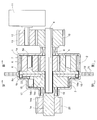
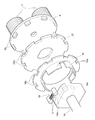
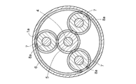
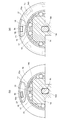
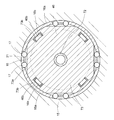
- Longitudinal front view of the speed reducer with brake according to the first embodiment 1 is an exploded perspective view of the main part of FIG. Sectional view along line III-III in FIG. Sectional view along line IV-IV in FIG. a and b are explanatory diagrams of the rotation transmission operation of the reverse input blocking mechanism of FIG.
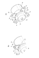
- Longitudinal front view showing a modification of the torque transmission means of the reverse input blocking mechanism a and b are cross-sectional views taken along the line VII-VII in FIG.
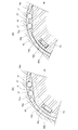
- Longitudinal front view showing a modified example of torque transmitting means and unlocking means of the reverse input blocking mechanism a and b are cross-sectional views taken along lines IXa-IXa and IXb-IXb in FIG. 8, respectively.
- FIG. 4A and 4B are exploded perspective views of main parts showing modifications of the housing assembly means, respectively.
- a and b are explanatory views of the housing assembling procedure by the assembling means of FIG.
- blocking mechanism of FIG. a and b are explanatory diagrams of the rotation transmission operation of the reverse input blocking mechanism of FIG.
- FIG. 18 is a longitudinal front view of the main part showing a modification of the brake reducer of FIG. Sectional view along line XXI-XXI in FIG.
- the speed reducer with brake according to the first embodiment is a unit in which a speed reduction mechanism 2 and a reverse input blocking mechanism 3 as a brake are arranged side by side in an axial direction inside a housing (fixed member) 1. It is incorporated into a drive unit of a device that operates a driven member by driving a motor.
- the housing 1 is divided into a front half 1a on the speed reduction mechanism 2 side and a rear half 1b on the reverse input blocking mechanism 3 side, and a flange 1c is formed at the abutting end of the front half 1a and the rear half 1b. ing.
- the plurality of mounting holes 1d opened at corresponding positions of both flanges 1c are used to connect the front half 1a and the rear half 1b and to fix the entire housing 1 within the apparatus.
- the speed reduction mechanism 2 includes an input shaft 4, a sun gear 5 fitted and fixed to the outer periphery of the input shaft 4, and a front half of the housing 1 on the radially outer side of the sun gear 5.
- 1a a plurality of planetary gears 7 meshing with both the sun gear 5 and the internal gear 6, and a support shaft 8a passed through the center of each planetary gear 7,
- It is a planetary gear mechanism comprising a disk-like carrier 8 that is supported so as to be able to rotate.
- the sun gear 5 is fitted and fixed to the outer periphery of the input shaft 4 by a key and a key groove (the same applies to fitting and fixing of other shafts and gears described later), but the input shaft 4 and the sun gear 5 are integrated. It may be formed.
- the input shaft 4 of the speed reduction mechanism 2 has one end side (left side in FIG. 1) passing through the center of the carrier 8 and protruding toward the reverse input blocking mechanism 3 side, and the other end side (right side in FIG. 1) is housing 1.
- the first half 1a of the housing 1 is passed through the housing 1 and is rotatably supported by the housing 1 via a bearing 9.
- the input gear 10 is fitted and fixed to the outer periphery of the protruding portion from the housing front half 1a.
- the input gear 10 meshes with a transmission gear 13 fitted and fixed to the outer periphery of the main shaft 12 of the drive motor 11, and rotation is transmitted from the drive motor 11 to the input shaft 4 via the transmission gear 13 and the input gear 10. It is like that.
- the carrier 8 is decelerated and rotated.
- a plurality of convex portions 8 b for transmitting rotation to the reverse input blocking mechanism 3 are provided on the outer peripheral portion of the carrier 8 at equal intervals in the circumferential direction. That is, the carrier 8 is an output side member of the speed reduction mechanism 2 and at the same time an input portion of the reverse input blocking mechanism 3.
- the carrier 8 may be divided into a portion serving as an output side member of the speed reduction mechanism 2 and a portion serving as an input portion of the reverse input blocking mechanism 3, and both of them may be coupled so as to transmit rotation.
- the reverse input blocking mechanism 3 is an output as an output unit connected to the carrier 8 as the input unit described above and a driven member (not shown) so as to be able to transmit rotation.
- a column portion 16a inserted between the outer peripheral surface and the annular unlocking piece 16 provided on the inner peripheral portion, and the outer peripheral surface of the large-diameter portion of the output shaft 14 and the inner peripheral surface of the fixed outer ring 15 are incorporated.
- the reverse input cutoff clutch includes a roller 17 and a coil spring 18.
- the output shaft 14 of the reverse input blocking mechanism 3 has a bearing hole 14a into which one end of the input shaft 4 of the speed reduction mechanism 2 is rotatably fitted at the center, and is arranged concentrically with the input shaft 4. Then, rotation is output to the driven member via an output gear 20 that is rotatably supported by the housing 1 via a bearing 19 and is fitted and fixed to the outer periphery of one end protruding from the housing rear half 1b. It has become.
- a plurality of cam surfaces 14 b perpendicular to the radial direction are provided on the outer periphery of the large-diameter portion of the output shaft 14, and both sides in the circumferential direction are provided between these cam surfaces 14 b and the inner peripheral cylindrical surface of the fixed outer ring 15.
- a wedge-shaped space 21 that is gradually narrowed is formed.
- a pair of rollers 17 are arranged in a state of sandwiching a coil spring 18 that pushes each roller 17 into a narrow portion of the wedge-shaped space 21.
- the column portion 16a of the unlocking piece 16 is inserted at a position facing the coil spring 18 across the coil.
- a first engagement hole 16 b into which the convex portion 8 b of the carrier 8 is inserted with a gap in the circumferential direction is provided on the outer peripheral portion of the unlocking piece 16.
- the other end portion 14c of the output shaft 14 is formed in an oval cross section, and a flange 22 sandwiched between the lock release piece 16 and the carrier 8 is fitted and fixed to the outer periphery thereof.
- a second engagement hole 22 a into which the convex portion 8 b of the carrier 8 is inserted with a wider circumferential clearance than the first engagement hole 16 b of the unlocking piece 16 is provided on the outer peripheral portion of the flange 22. .
- the reverse input blocking mechanism 3 includes a lock unit that locks the output shaft 14 to the fixed outer ring 15, and the output shaft 14 and the fixed outer ring by rotation of the carrier 8 when input torque is applied to the carrier 8 (input unit). And a lock release means for releasing the locked state with the motor 15 and a torque transmitting means for transmitting the rotation of the carrier 8 to the output shaft 14 with a slight angular delay when the locked state is released. It is.
- the speed reducer with a brake is a reduction mechanism 2 that decelerates the rotation of the drive motor 11 and outputs it to the driven member side, and a brake that holds the position of the driven member when the drive motor 11 stops.
- the lock type reverse input blocking mechanism 3 is unitized, and the reverse input blocking mechanism 3 is mechanically locked against the reverse input torque applied from the driven member. It is not necessary and can be easily incorporated into the device. Therefore, the apparatus incorporating the speed reducer with a brake consumes less power and can perform the assembly work more efficiently than the apparatus incorporating the non-excitation operation type electromagnetic brake and the speed reducer separately. Further, since the torque applied to the driven member from the outside during the stop is loaded by the reverse input blocking mechanism 3 and is not transmitted to the speed reduction mechanism 2, the protection function of the speed reduction mechanism 2 is also excellent.
- the convex portion 8 b of the carrier 8 serving as the input portion is formed in the first engagement hole 16 b of the lock release piece 16 and the second engagement hole 22 a of the flange 22 of the output shaft 14. Since it is inserted with a clearance in the circumferential direction and is engaged with each engagement hole 16b, 22a in order to perform unlocking and subsequent rotation transmission, each engagement hole 16b, 22a and projection 8b By appropriately designing the circumferential clearance, rotation transmission can be performed in a state where the lock is reliably released, and the time delay from the unlocking to the start of torque transmission can be reduced.
- FIG. 6 and 7 (a) and 7 (b) show modifications of the torque transmission means of the reverse input blocking mechanism 3.
- FIG. In this modification, one end portion of the input shaft 4 is shortened and is rotatably fitted in a bearing hole 8c at the center of the input side surface of the carrier 8, and a rotation transmission shaft 8d having an oval cross section is provided at the center of the output side end surface of the carrier 8. Yes.
- the output shaft 14 has the other end portion 14c having an oval cross section and the flange 22, and the rotation transmission shaft 8d of the carrier 8 is inserted in place of the bearing hole 14a into which the one end portion of the input shaft 4 is fitted.
- An engagement hole 14d is provided.
- the third engagement hole 14d has substantially the same shape as the rotation transmission shaft 8d, but the engagement surface facing the flat portion of the rotation transmission shaft 8d is formed in a convex shape.
- FIG. 8 and 9 (a) and 9 (b) show an example in which the lock release means is deformed in addition to the above-described deformation of the torque transmission means for the reverse input blocking mechanism 3.
- FIG. This modification is based on the example shown in FIG. 6 and FIGS. 7A and 7B, eliminates the convex portion 8b of the carrier 8, and has a column portion 16a on the outer peripheral portion as the unlocking piece 16.
- a disc-shaped member in which one engagement hole 16b is not formed is adopted, and the lock release piece 16 is fitted and fixed to the outer periphery of a rotation transmission shaft 8d having a small cross-sectional shape of the carrier 8.
- FIGS. 10A and 10B and FIGS. 11A and 11B show modified examples of the assembly means of the housing 1.
- the housing 1 of this modification is provided with the same mounting pieces 1e and 1f instead of the flange 1c at the butting ends of the front half 1a and the rear half 1b. Two are provided so as to face each other across the center of the housing 1.
- the mounting piece 1e of the front half 1a is composed of a base 1e1 extending in the radial direction from the abutting end of the front half 1a, and a substantially triangular plate-shaped main body 1e2 projecting in the radial direction from the tip of the base 1e1.
- a notch 1g is formed between the ends.
- the mounting piece 1f of the rear half 1b is composed of a base 1f1 extending in the axial direction from the butted end of the rear half 1b and a substantially triangular plate-like main body 1f2 projecting radially from the tip of the base 1f1.
- a cut 1h is formed between the end and the butted end.
- the positional relationship in the circumferential direction between the base portion 1f1 and the notch 1h is opposite to the circumferential positional relationship between the base portion 1e1 of the mounting piece 1e of the front half 1a and the notch 1g. Further, mounting holes 1d are formed in the main body portions 1e2, 1f2 of the mounting pieces 1e, 1f.
- the front half 1a and the rear half 1b have slits on both sides in the circumferential direction of the bases 1e1 and 1f1 of the mounting pieces 1e and 1f. Thereby, when the attachment pieces 1e and 1f are formed by bending, the base portions 1e1 and 1f1 do not protrude from the end surface in the axial direction, and the end surfaces of the front half portion 1a and the rear half portion 1b can be abutted with each other without any gap. .
- the housing 1 is assembled by attaching the front half 1a and the rear half 1b to each other in such a manner that the mounting pieces 1e and 1f do not overlap each other in the axial direction.
- 1e, 1f cuts 1g, 1h are relatively rotated in the direction in which they approach each other (in the figure, only the latter half 1b is rotated).
- the base 1f1 of the other mounting piece 1f enters the cut 1g of the one mounting piece 1e
- the base 1e1 of the one mounting piece 1e enters the cut 1h of the other mounting piece 1f.
- the both attachment pieces 1e, 1f are engaged with each other in the axial direction, and the front half 1a and the rear half 1b are integrated in the axial direction.
- the mounting holes 1d of both the mounting pieces 1e and 1f are also overlapped, the integrated front half 1a and rear half 1b may be fixed in the apparatus using the mounting holes 1d.
- the housing 1 can be stored and transported with the front half 1a and the latter half 1b being integrated, and FIGS. 1 to 9 (a) (b). It is easier to handle than the example shown in. Further, as another modification of the housing assembly means, in contrast to the example shown in FIGS. 1 to 9 (a) and 9 (b), the other edge of the notch provided on one of the flanges of the front half and the rear half is provided on the other side. In this case, it is necessary to bend the nail when the first half and the second half are integrated.
- the front half 1a and the rear half 1b can be integrated by simply rotating relative to each other, and it is not time-consuming at the time of assembling the housing 1, and it is easy to disassemble after assembly so that it can be easily reused. There is an advantage.
- an attachment piece 1e having a base 1e1 extending in the radial direction is provided in the front half 1a, and a base extending in the axial direction is provided in the rear half 1b.
- the attachment piece 1f having 1f1 is provided, both attachment pieces 1e and 1f may be provided so as to be reversed.
- the modified example of the housing assembly means can be widely applied to a speed reducer with a single speed reduction mechanism, a housing such as a reverse input cutoff clutch, and the like.
- FIG. 12 shows a second embodiment.
- a differential speed reduction mechanism in which two planetary gear mechanisms (a first planetary gear mechanism 31 and a second planetary gear mechanism 41) are incorporated side by side in the axial direction. 23 is adopted.
- the structure from the drive motor 11 to the speed reduction mechanism 23 is changed according to it, and the front half part 1a of the housing 1 is also changed so that the changed part may be covered.
- the configuration of the reverse input blocking mechanism 3 as a brake is the same as that of the first embodiment.
- the first planetary gear mechanism 31 is arranged on a radially outer side of the first input shaft 32 having a cylindrical shape, a first sun gear 33 formed integrally with the first input shaft 32, and the first sun gear 33.
- the first carrier 36 is formed integrally with the housing front half 1a.
- the first input shaft 32 passes through the center of the first carrier 36 and is rotatably supported by the first carrier 36 via a bearing 37.
- the first input shaft 32 is provided on the outer periphery of the protruding portion from the first carrier 36.
- One input gear 24 is fitted and fixed.
- the second planetary gear mechanism 41 includes a second input shaft 42 that rotatably penetrates the first input shaft 32 of the first planetary gear mechanism 31 and a second input shaft 42 that protrudes from one end of the first input shaft 32.
- a second sun gear 43 formed integrally with the projecting portion, a second internal gear 44 formed integrally with the first internal gear 34 and arranged radially outside the second sun gear 43, and a second sun gear And a plurality of second planetary gears 45 meshing with both the second planetary gears 44 and a support shaft 46a that passes through the center of each of the second planetary gears 45, and supports the second planetary gears 45 so that they can rotate.
- the second carrier 46 Similar to the carrier 8 of the first embodiment, the second carrier 46 is provided with a plurality of convex portions 46 b for transmitting rotation to the reverse input blocking mechanism 3.
- the second input shaft 42 of the second planetary gear mechanism 41 has one end passing through the center of the carrier 36 and a bearing hole of the output shaft 14 of the reverse input blocking mechanism 3. 14a is rotatably fitted.
- the second input gear 25 is fitted and fixed to the outer periphery of the projecting portion from the other end of the first input shaft 32, and the other end is rotatably supported by the housing 1 via a bearing 47.
- a disc-like spacer 26 for preventing contact between the planetary gears 35 and 45 of the first planetary gear mechanism 31 and the second planetary gear mechanism 41 is fitted and fixed at a position adjacent to the second sun gear 43. Has been.
- the gear specifications of the respective parts of the first planetary gear mechanism 31 and the second planetary gear mechanism 41 are the same, and the gear specifications of the first input gear 24 and the second input gear 25 are different.
- a drive shaft 27 having one end rotatably supported by the first carrier 36 is connected to the main shaft 12 of the drive motor 11, and a first transmission gear fitted and fixed to the outer periphery of the drive shaft 27.
- the first input gear 24 and the second input gear 25 mesh with the 28 and the second transmission gear 29, respectively.
- rotation is transmitted from the drive motor 11 to the input shafts 32 and 42 via the transmission gears 28 and 29 and the input gears 24 and 25, and the first input shaft 32 and the second input shaft 42 have different rotations. A number of rotations are entered simultaneously.
- the drive motor 11 drives the first input shaft 32 and the second input shaft 42 to rotate at different rotational speeds as described above.
- the first planetary gear mechanism 31 since the first carrier 36 is fixed, the first planetary gear 35 rotates in a state in which the revolution is restrained, and the first internal gear 34 is moved to the first input shaft 32. Rotate in the opposite direction.
- the second planetary gear mechanism 41 since the second internal gear 44 rotates integrally with the first internal gear 34, the rotation of the first input shaft 32 and the second input shaft 42 while the second planetary gear 45 rotates.
- the second carrier 46 rotates by the revolution of the second planetary gear 45 according to the difference in number, and the reverse input blocking mechanism 3 is unlocked and the output shaft 14 is released as in the first embodiment. Rotational transmission is performed.
- a disk-like manual operation portion 30 is fitted and fixed to the outer periphery of the protruding portion from the housing front half portion 1a of the drive shaft 27 serving as the input side member of the speed reduction mechanism 23, and the drive motor 11 is stopped.
- the position (posture) of the driven member can be changed by rotating the manual operation unit 30 as necessary.
- the position of the manual operation unit 30 is, as indicated by the alternate long and short dash line in the figure, by projecting the main shaft 12 from the drive motor 11 to the side opposite to the side facing the speed reduction mechanism 23 and at the end of the manual operation unit 30. 30, or as shown by a two-dot chain line in the figure, another set of drive shaft 27, first transmission gear 28 and second transmission gear 29 is provided, and the other end of the drive shaft 27 is provided.
- the manual operation unit 30 may be attached.
- the brake is a conventional non-excitation operation type electromagnetic brake
- the brake is energized to release the brake. After that, it is necessary to rotate the manual operation unit or to apply a torque exceeding the braking force in a state where the brake is applied, and to rotate the manual operation unit. 3 is adopted, the position of the driven member can be changed by easily rotating the manual operation unit 30 in a safe state where the brake is applied.
- the manual operation unit 30 can be attached to and detached from the drive shaft 27 (or the main shaft 12 of the drive motor 11) with a screw or the like. Thereby, the space required during operation can be reduced by removing the manual operation unit 30 during normal motor driving.
- FIG. 13 shows a third embodiment.
- a speed reduction mechanism 50 in which two planetary gear mechanisms 51 and 61 are incorporated in two stages is adopted, and a housing is provided so as to cover the speed reduction mechanism 50.
- the first half 1a of 1 is also changed.
- the configuration of the reverse input blocking mechanism 3 as a brake is the same as that of the first embodiment.
- the first-stage planetary gear mechanism 51 includes an input shaft 52 formed integrally with the drive motor main shaft 12 and the sun gear 53, an internal gear 54 fixed to the housing first half 1a on the radially outer side of the sun gear 53, A plurality of planetary gears 55 meshing with both the sun gear 53 and the internal gear 54, and a carrier 56 having a support shaft 56a passed through the center of each planetary gear 55 and supporting each planetary gear 55 in a rotatable manner. .
- the second stage planetary gear mechanism 61 includes an input shaft 62 formed integrally with the first stage carrier 56 and the sun gear 63, and an internal gear 64 fixed to the housing front half 1a on the radially outer side of the sun gear 63.
- a plurality of planetary gears 65 meshing with both the sun gear 63 and the internal gear 64, and a support shaft 66a that passes through the center of each planetary gear 65, and a carrier 66 that supports each planetary gear 65 in a rotatable manner. Consists of.
- the second-stage carrier 66 is provided with a plurality of convex portions 66b for transmitting rotation to the reverse input blocking mechanism 3, and a protruding shaft portion 66c protruding from one end surface.
- the reverse input blocking mechanism 3 is rotatably fitted in the bearing hole 14a of the output shaft 14.
- one end of the second stage input shaft 62 is rotatably fitted in the center of the other end of the second stage carrier 66, and the other end side center of the input shaft 62 (first stage carrier 56) is fitted.
- One end of the first-stage input shaft 52 is rotatably fitted in the part.
- the main shaft 12 of the drive motor 11 also protrudes from the drive motor 11 to the side opposite to the side facing the speed reduction mechanism 50, and a manual operation unit 67 is attached to the end thereof.
- the manual operation unit 67 can be rotated as necessary to change the position (posture) of the driven member. .
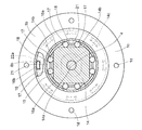
- FIGS. 14 to 17 (a) and 17 (b) show a fourth embodiment.
- This embodiment is obtained by changing a part of the configuration of the reverse input blocking mechanism 3 and the differential reduction mechanism 23 of the second embodiment. Therefore, members having the same functions as those of the second embodiment are denoted by the same reference numerals and description thereof is omitted, and differences from the second embodiment will be mainly described below.
- a housing 71 having no step on the outer peripheral surface is used, the drive motor 11 is incorporated in the front half 71a, and the speed reduction mechanism 23 and the reverse input blocking mechanism are installed in the rear half 71b. 3 is incorporated.
- the front half portion 71a of the housing is provided with an inner cylinder portion 71c extending inward in the axial direction from the center portion of the lid portion, and the output side end portion of the rear half portion 71b is separately provided as a fixed outer ring 15 of the reverse input blocking mechanism 3. Is formed.
- first planetary gear mechanism 31 and the second planetary gear mechanism 41 of the speed reduction mechanism 23 have a common input shaft 72, and the output portion of the reverse input blocking mechanism 3 faces the inner peripheral surface of the fixed outer ring 15.
- the cam member 73 is divided into an output shaft 74 that is fixed to the outer surface in the axial direction.
- the cam member 73 and the output shaft 74 are provided with screw holes for integrating them.
- the input shaft 72 of the speed reduction mechanism 23 and the output shaft 74 of the reverse input blocking mechanism 3 are hollow shafts having the same inner diameter as the inner cylinder portion 71c of the housing 71, and the housing inner cylinder portion 71c, the input shaft 72, and the output shaft 74.
- a cable (not shown) for controlling the drive motor 11 can be passed through the inside.
- an input gear 75 is fitted and fixed to the outer periphery of a portion of the input shaft 72 that is adjacent to the housing inner cylindrical portion 1 c in the axial direction.
- the rotation is input from the drive motor 11 by meshing with the fixed transmission gear 76.
- the transmission gear 76 one having a smaller number of teeth (smaller diameter) than the input gear 75 is used.
- the first sun gear 33 is fitted and fixed to the outer periphery of the input shaft 72, the second sun gear 43 is formed integrally with the input shaft 72, the first internal gear 34 and the second internal gear 44 are
- the second embodiment is that the first planetary gear 35 is supported by a first carrier 36 that is integral with the housing 71 so that the first planetary gear 35 protrudes from the center of the first planetary gear 35 so as to rotate. Is different.
- the revolution of the second planetary gear 45 is transmitted to the output side via the second carrier 46.
- only one drive motor 11 is arranged in the housing 71, but a plurality of drive motors 11 are arranged around the axis of the input shaft 72, and the main shaft 12 of each drive motor 11 is arranged. If the transmission gear 76 meshing with the input shaft 72 is fitted and fixed on the outer periphery, the output can be easily adjusted by changing the number of the drive motors 11.
- the reverse input blocking mechanism 3 of the fourth embodiment is provided with a plurality of cam surfaces 73a similar to those of the second embodiment on the outer periphery of the cam member 73 constituting the output portion.
- the flange 22 of the second embodiment is eliminated by providing the engaging hole 73b into which the convex portion 46b of the second carrier 46 is inserted with a circumferential clearance at the outer peripheral portion of the input side surface of the cam member 73.
- the lock release piece 16 has an arrangement of the column portion 16a and the engagement recess portion 16b opposite to that of the second embodiment, the column portion 16a is provided on the outer peripheral portion, and the convexity of the second carrier 46 on the inner peripheral portion.
- An engagement recess 16 b is provided in which the portion 46 b is inserted with a circumferential clearance narrower than the engagement hole 73 b of the cam member 73.
- the operation of the reverse input blocking mechanism 3 is almost the same as that of each of the embodiments described above. That is, even when reverse input torque is applied from the driven member to the output shaft 74 and the cam member 73, the roller 17 on the rear side in the rotational direction is pushed into the narrow portion of the wedge-shaped space 21 by the elastic force of the coil spring 18. The cam member 73 is locked to the fixed outer ring 15, the cam member 73 and the output shaft 74 do not rotate, and the position of the driven member does not change.
- the output shaft 74 is rotatably supported by a bearing 78 provided on the inner periphery of the bearing housing 77, and the output shaft 74 is interposed between the output shaft 74 and the bearing housing 77.
- a rotation detection mechanism 79 is provided for detecting the number of rotations.
- the rotation detection mechanism 79 is a base disposed so as to be sandwiched between an encoder 80 attached to a step surface at the axial center of the outer peripheral portion of the output shaft 74, the bearing housing 77, and the fixed outer ring 15 of the reverse input blocking mechanism 3.
- the rotation detection mechanism 79 detects the rotation speed of the output shaft 74 and corrects the drive rotation speed of the drive motor 11 in accordance with the difference from the target rotation speed, thereby changing the rotation speed of the output shaft 74 to the target rotation speed. I try to get closer to the number. As a result, even if there is a loss of rotation transmission in the first and second planetary gear mechanisms 31, 41, the reverse input blocking mechanism 3 and the like interposed between the drive motor 11 and the output shaft 74, the output shaft 74 is substantially targeted. It can be rotated at the number of rotations.
- the housing 71, the bearing housing 77, and the base member 81 of the rotation detection mechanism 79 are provided with concentric positioning steps that fit into the axially opposed surfaces and the dividing surface of the housing 71, respectively.
- the bolts 71d, 77a, 81a passing through the corresponding positions on the outer peripheral side of each member in a state in which the steps are fitted, and the bolts passed through the bolt holes 71d, 77a, 81a They are integrated with nuts (both not shown).
- the step of each member can be eliminated. However, if the step is provided as in this embodiment, alignment of the bolt holes 71d, 77a, 81a is facilitated, and the entire reduction gear is efficiently assembled. This is preferable.
- screw holes 77b and 81b are formed at corresponding positions on the outer sides in the radial direction of the through holes 77a and 81a of the bearing housing 77 and the base member 81, and are fixed in the apparatus using these screw holes 77b and 81b. It has come to be.
- the drive motor 11, the speed reduction mechanism 23, the reverse input blocking mechanism 3 as a brake, and the rotation detection mechanism 79 are unitized. It is suitable for incorporation into.
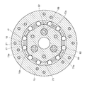
- a wave gear device using a difference between an ellipse and a perfect circle is employed as a speed reduction mechanism 84 that replaces the speed reduction mechanisms 2, 23, and 50 using the planetary gear mechanisms of the first to fourth embodiments.
- an annular mounting member 91 that replaces the housing 1 is disposed in the central portion in the axial direction of the entire speed reducer.
- the attachment member 91 has a plurality of screw holes 91a formed in the outer peripheral portion thereof, and is fixed in the apparatus using these screw holes 91a.
- the speed reduction mechanism (wave gear device) 84 includes a wave generator 85 coupled to the main shaft 12 of the hollow drive motor 11 so as to be able to transmit rotation, a circular spline 86 disposed radially outward of the wave generator 85, and a wave generator.
- a flex spline 87 having a large diameter portion sandwiched between 85 and the circular spline 86 is provided.
- the circular spline 86 is arranged so as to be adjacent to the attachment member 91 in the axial direction, and is attached by bolt connection between the flange portion 11a of the drive motor 11 that sandwiches both of them in the axial direction and the fixed outer ring 15 of the reverse input blocking mechanism 3.
- the member 91, the drive motor 11, and the fixed outer ring 15 are integrated.
- the wave generator 85 is obtained by fitting and fixing an inner ring of a ball bearing 85b on the outer periphery of a cam 85a having an elliptical cross section in the radial direction.
- the wave generator 85 is connected to the main shaft 12 of the drive motor 11 via a hollow detent member 88. This is an input side member of the speed reduction mechanism 84.
- the circular spline 86 is an annular part having teeth provided on the inner periphery thereof, and is fixed in the apparatus via an attachment member 91.
- the flex spline 87 is a thin cup-shaped part formed of a metal elastic body, and teeth that mesh with teeth on the inner periphery of the circular spline 86 are provided on the outer periphery of the large diameter portion.
- the reverse input blocking mechanism 3 is connected to an input pin 89 serving as an input portion so as to be able to transmit rotation, and serves as an output side member of the speed reduction mechanism 84.
- the flex spline 87 whose large diameter inner periphery is pressed by the outer ring of the ball bearing 85 b of the wave generator 85 is elastically deformed to change the meshing position with the circular spline 86.
- the rotation is made by the difference in the number of teeth from the circular spline 86, and the rotation is transmitted to the input pin 89 of the reverse input blocking mechanism 3.
- a cylindrical guide member 90 is fixed at a position in sliding contact with the end surface (other end surface) of the large-diameter portion of the flex spline 87.
- the wave gear device is employed as the speed reduction mechanism 84, a high speed reduction rate can be obtained, and the two planetary gear mechanisms can be moved in the axial direction as in the second to fourth embodiments.
- the structure of the entire speed reducer can be simplified and the axial dimension can be made compact.
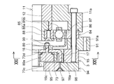
- a sleeve 92 fitted and fixed to the outer periphery on the distal end side of an input pin 89 serving as an input portion is attached to a cam member 73 serving as an output portion of the reverse input blocking mechanism 3 instead of the engagement hole 73b of the fourth embodiment.
- the lock release piece 16 is provided with an engagement hole 16c into which the central portion of the input pin 89 is inserted with a circumferential clearance instead of the engagement recess 16b of the fourth embodiment.
- the circumferential clearance between the engagement hole 16 c of the lock release piece 16 and the central portion of the input pin 89 is narrower than the circumferential clearance between the engagement hole 73 c of the cam member 73 and the sleeve 92.
- a cross roller bearing 94 is provided between the cam member 73 of the reverse input blocking mechanism 3 and the connecting member 93 connected to the driven member.
- the cross roller bearing 94 includes a plurality of rollers 97 arranged between an inner ring 95 and an outer ring 96 so that adjacent ones in the circumferential direction are orthogonal to each other, and the inner ring 95 is integrated with the cam member 73 and the connecting member 93.
- the outer ring 96 is bolted to the fixed outer ring 15 of the reverse input blocking mechanism 3. Thereby, the rigidity with respect to the thrust force of the entire reduction gear is increased, and the stability of the rotation transmission operation is increased.
- a rotation detection mechanism 79 similar to that in the fourth embodiment is provided between the outer ring 96 of the cross roller bearing 94 and the connection member 93.
- the rotation detection mechanism 79 is attached to the outer end surface of the outer ring 96 of the outer ring 96 of the cross roller bearing 94 and the encoder 80 attached to the inner side surface of the ring member 98 having a substantially U-shaped cross section fitted and fixed to the outer peripheral surface of the connection member 93.
- the electronic board 83 includes a sensor 82 attached to the electronic board 83 so as to face the encoder 80 in the axial direction.
- the rotation detection mechanism 79 detects the rotation speed of the connection member 93 and the ring member 98 that rotate integrally with the cam member 73 of the reverse input blocking mechanism 3, and drives the drive motor 11 according to the difference from the target rotation speed.
- the rotational speed accuracy can be improved by correcting the rotational speed.
- a large-diameter portion 89a is provided in place of the sleeve 92 on the distal end side of the input pin 89 that passes through the small-diameter portion of the flex spline 87 and the unlocking piece 16, and the large-diameter portion 89a and the small-diameter portion of the flex spline 87 are provided.
- the nut 99 that is screw-coupled to the portion protruding from the pin is clamped by sandwiching the small diameter portion of the flex spline 87 and the lock release piece 16.
- An annular guide portion 73 d that is inserted between the step surface provided in the middle of the large-diameter portion 89 a of the input pin 89 and the lock release piece 16 is provided on the periphery of the engagement hole 73 c of the cam member 73. .
- the guide portion 73d of the cam member 73 engages with the large-diameter portion 89a of the input pin 89, and the axial movement of the flex spline 87 and the lock release piece 16 toward the other end side is restricted.
- the guide member 90 slidably contacting the end surface of the large-diameter portion of the flex spline 87 can be omitted to reduce the number of parts, and after the reverse input blocking mechanism 3 is unlocked Since the input pin 89 pushes the cam member 73 and rotates almost integrally with the cam member 73, the number of sliding parts is reduced, and the torque of the entire speed reducer can be reduced.
Landscapes
- Engineering & Computer Science (AREA)
- General Engineering & Computer Science (AREA)
- Mechanical Engineering (AREA)
- Physics & Mathematics (AREA)
- Electromagnetism (AREA)
- Transportation (AREA)
- Robotics (AREA)
- Retarders (AREA)
- Braking Arrangements (AREA)
- Manipulator (AREA)
Abstract
L'invention concerne un frein qui ne requiert aucune énergie électrique et qui est donc facilement incorporé dans un appareil dans lequel un élément entraîné est actionné par l'entraînement d'un moteur. Un engrenage réducteur doté d'un frein est incorporé dans un appareil permettant d'entraîner un moteur d'entraînement (11) pour actionner un élément entraîné, ledit engrenage réducteur combinant, en une unité, un mécanisme de réduction (2) permettant de réduire la rotation du moteur d'entraînement (11) et de produire une rotation réduite du côté de l'élément entraîné et un mécanisme de blocage d'entrée inversée de verrouillage (3) sous la forme d'un frein permettant un verrouillage mécanique en réponse à un couple d'entrée inversée communiqué depuis l'élément entraîné et maintenant la position de l'élément entraîné lorsque le moteur d'entraînement (11) est stoppé.
Priority Applications (3)
| Application Number | Priority Date | Filing Date | Title |
|---|---|---|---|
| US15/114,553 US20160341267A1 (en) | 2014-01-28 | 2015-01-23 | Speed reducer with a brake |
| CN201580006342.7A CN105940246A (zh) | 2014-01-28 | 2015-01-23 | 带制动器的减速机 |
| EP15743664.3A EP3101314A4 (fr) | 2014-01-28 | 2015-01-23 | Engrenage réducteur doté d'un frein |
Applications Claiming Priority (6)
| Application Number | Priority Date | Filing Date | Title |
|---|---|---|---|
| JP2014-013311 | 2014-01-28 | ||
| JP2014013311 | 2014-01-28 | ||
| JP2014078373 | 2014-04-07 | ||
| JP2014-078373 | 2014-04-07 | ||
| JP2014209700A JP2015206455A (ja) | 2014-01-28 | 2014-10-14 | ブレーキ付減速機 |
| JP2014-209700 | 2014-10-14 |
Publications (1)
| Publication Number | Publication Date |
|---|---|
| WO2015115324A1 true WO2015115324A1 (fr) | 2015-08-06 |
Family
ID=53756898
Family Applications (1)
| Application Number | Title | Priority Date | Filing Date |
|---|---|---|---|
| PCT/JP2015/051823 WO2015115324A1 (fr) | 2014-01-28 | 2015-01-23 | Engrenage réducteur doté d'un frein |
Country Status (5)
| Country | Link |
|---|---|
| US (1) | US20160341267A1 (fr) |
| EP (1) | EP3101314A4 (fr) |
| JP (1) | JP2015206455A (fr) |
| CN (1) | CN105940246A (fr) |
| WO (1) | WO2015115324A1 (fr) |
Cited By (6)
| Publication number | Priority date | Publication date | Assignee | Title |
|---|---|---|---|---|
| WO2017186844A1 (fr) * | 2016-04-27 | 2017-11-02 | Ovalo Gmbh | Articulation motorisée pour un automate de déplacement programmable |
| WO2017186845A1 (fr) * | 2016-04-27 | 2017-11-02 | Ovalo Gmbh | Articulation motorisée pour un automate de déplacement programmable |
| WO2017186843A1 (fr) * | 2016-04-27 | 2017-11-02 | Ovalo Gmbh | Articulation motorisée pour un robot manipulateur programmable |
| CN110033692A (zh) * | 2019-04-28 | 2019-07-19 | 重庆理工大学 | 一种行星齿轮机构运动教学装置 |
| US11111984B2 (en) | 2016-08-05 | 2021-09-07 | Fanuc Corporation | Rotary axis module and articulated robot |
| CN113618774A (zh) * | 2021-07-19 | 2021-11-09 | 安徽工程大学 | 一种基于凸轮机构的变刚度传动关节及切换控制方法 |
Families Citing this family (19)
| Publication number | Priority date | Publication date | Assignee | Title |
|---|---|---|---|---|
| EP3412930B1 (fr) * | 2016-02-02 | 2020-12-09 | Harmonic Drive Systems Inc. | Dispositif d'engrenage à ondes de déformation et actionneur |
| DE112017005329B9 (de) * | 2016-10-19 | 2021-06-24 | Mitsubishi Electric Corporation | Drehzahlminderer und Roboter |
| US11564452B2 (en) * | 2016-12-09 | 2023-01-31 | Adamant Namiki Precision Jewel Co., Ltd. | Winding device |
| HUE043223T2 (hu) * | 2017-01-24 | 2019-08-28 | Lakeview Innovation Ltd | Kompakt többlépcsõs hajtómû bolygóhajtómûvel és egy ahhoz csatlakozó tengelyhajtómûvel |
| FR3065266B1 (fr) * | 2017-04-14 | 2020-07-31 | Bernard Controls | Train epicycloidal avantageusement pour un systeme servomoteur et systeme servomoteur utilisant ce train epicycloidal |
| JP2019163698A (ja) * | 2018-03-19 | 2019-09-26 | 日立オートモティブシステムズ株式会社 | 内燃機関の可変圧縮比機構のアクチュエータおよび波動歯車減速機 |
| US11027438B2 (en) * | 2018-07-13 | 2021-06-08 | A-Dec, Inc. | Positive positioning device and system |
| CN109129552B (zh) * | 2018-09-19 | 2023-10-03 | 广东工业大学 | 一种基于楔形块的机器人连接组件 |
| TW202033338A (zh) * | 2019-01-30 | 2020-09-16 | 日商京洛股份有限公司 | 成型裝置、以及成型品的製造系統 |
| CA3131375A1 (fr) * | 2019-02-25 | 2020-09-03 | Moog Inc. | Module d'arret sans blocage a liaison automatique pour actionneur d'entrainement rotatif |
| CN109895081A (zh) * | 2019-04-30 | 2019-06-18 | 深圳市爱因派科技有限公司 | 机电一体化的高精度舵机及机器人 |
| US11696806B2 (en) * | 2019-07-23 | 2023-07-11 | Verb Surgical Inc. | Strain wave gearing with input to output braking |
| WO2021056173A1 (fr) | 2019-09-24 | 2021-04-01 | Shanghai Flexiv Robotics Technology Co., Ltd. | Mécanisme de frein, actionneur d'articulation et robot |
| CN112936334B (zh) * | 2021-02-10 | 2022-07-12 | 镇江星河机器人有限公司 | 一种机器人关节模块电机及其精准控制方法 |
| FR3127268A1 (fr) * | 2021-09-17 | 2023-03-24 | Robocath | Bras articule de support de robot catheter de manipulation d’instrument medical souple allonge comprenant un frein |
| CN113833780B (zh) * | 2021-10-21 | 2023-07-25 | 杭州速博雷尔传动机械有限公司 | 一种高效双制动减速机 |
| TWI785874B (zh) * | 2021-11-02 | 2022-12-01 | 財團法人工業技術研究院 | 傳動模組 |
| DE202022103346U1 (de) | 2022-06-14 | 2023-09-22 | Dellner Bubenzer Germany Gmbh | Tachoanordnung für eine Motoranbaubremse, Motoranbaubremse und Antriebsanordnung |
| CN115553924B (zh) * | 2022-12-02 | 2023-03-10 | 北京云力境安科技有限公司 | 一种柔性器械输送装置及其执行部件、驱动部件 |
Citations (11)
| Publication number | Priority date | Publication date | Assignee | Title |
|---|---|---|---|---|
| JPS6023654A (ja) | 1983-07-15 | 1985-02-06 | Hitachi Ltd | 変速機 |
| JPS6372943A (ja) * | 1986-09-10 | 1988-04-02 | Fujio Hisashi | 歯車減速伝動装置 |
| JPH06285785A (ja) | 1993-03-31 | 1994-10-11 | Yaskawa Electric Corp | 産業用ロボットのアーム退避装置および退避方法 |
| JPH0783293A (ja) * | 1993-09-14 | 1995-03-28 | Secoh Giken Inc | 差動スターギア装置 |
| JP2003056596A (ja) * | 2001-08-09 | 2003-02-26 | Ntn Corp | クラッチ付き回転装置 |
| JP2003083416A (ja) * | 2001-09-13 | 2003-03-19 | Sumitomo Heavy Ind Ltd | 成形機用ボールねじ潤滑装置及び潤滑方法 |
| JP2004162730A (ja) * | 2002-11-08 | 2004-06-10 | Ntn Corp | 磁気浮上回転装置 |
| JP2007321879A (ja) * | 2006-06-01 | 2007-12-13 | Harmonic Drive Syst Ind Co Ltd | 回転位置センサ付き減速機ユニット |
| JP2009166168A (ja) * | 2008-01-15 | 2009-07-30 | Sumitomo Heavy Ind Ltd | ロボットの関節駆動装置 |
| JP2010041747A (ja) * | 2008-07-31 | 2010-02-18 | Chiba Inst Of Technology | モータ装置 |
| JP2013099191A (ja) * | 2011-11-04 | 2013-05-20 | Seiko Epson Corp | 電気機械装置およびそれを用いたアクチュエーター、モーター、ロボット、ロボットハンド。 |
Family Cites Families (9)
| Publication number | Priority date | Publication date | Assignee | Title |
|---|---|---|---|---|
| US2240043A (en) * | 1939-12-28 | 1941-04-29 | Kinser Vernon | Automatic shaft brake device |
| GB2210941B (en) * | 1987-10-09 | 1991-11-13 | Ntn Toyo Bearing Co Ltd | Clutch |
| JP2002213486A (ja) * | 2001-01-22 | 2002-07-31 | Ntn Corp | 回転駆動装置 |
| EP1239178B1 (fr) * | 2001-03-08 | 2004-12-15 | Ntn Corporation | Embrayage de blocage contre entrée en sens inverse |
| JP2003166570A (ja) * | 2001-11-29 | 2003-06-13 | Advics:Kk | 電動パーキングブレーキ装置 |
| JP4789000B2 (ja) * | 2006-02-16 | 2011-10-05 | Smc株式会社 | 減速比自動切換装置 |
| CN100369724C (zh) * | 2006-02-28 | 2008-02-20 | 哈尔滨工业大学 | 空间机械臂模块化关节 |
| WO2010004880A1 (fr) * | 2008-07-09 | 2010-01-14 | Ntn株式会社 | Démultiplicateur et dispositif de distribution à soupape variable l'utilisant |
| JP2012122585A (ja) * | 2010-12-10 | 2012-06-28 | Ntn Corp | 逆入力遮断クラッチ |
-
2014
- 2014-10-14 JP JP2014209700A patent/JP2015206455A/ja active Pending
-
2015
- 2015-01-23 CN CN201580006342.7A patent/CN105940246A/zh active Pending
- 2015-01-23 WO PCT/JP2015/051823 patent/WO2015115324A1/fr active Application Filing
- 2015-01-23 EP EP15743664.3A patent/EP3101314A4/fr not_active Withdrawn
- 2015-01-23 US US15/114,553 patent/US20160341267A1/en not_active Abandoned
Patent Citations (11)
| Publication number | Priority date | Publication date | Assignee | Title |
|---|---|---|---|---|
| JPS6023654A (ja) | 1983-07-15 | 1985-02-06 | Hitachi Ltd | 変速機 |
| JPS6372943A (ja) * | 1986-09-10 | 1988-04-02 | Fujio Hisashi | 歯車減速伝動装置 |
| JPH06285785A (ja) | 1993-03-31 | 1994-10-11 | Yaskawa Electric Corp | 産業用ロボットのアーム退避装置および退避方法 |
| JPH0783293A (ja) * | 1993-09-14 | 1995-03-28 | Secoh Giken Inc | 差動スターギア装置 |
| JP2003056596A (ja) * | 2001-08-09 | 2003-02-26 | Ntn Corp | クラッチ付き回転装置 |
| JP2003083416A (ja) * | 2001-09-13 | 2003-03-19 | Sumitomo Heavy Ind Ltd | 成形機用ボールねじ潤滑装置及び潤滑方法 |
| JP2004162730A (ja) * | 2002-11-08 | 2004-06-10 | Ntn Corp | 磁気浮上回転装置 |
| JP2007321879A (ja) * | 2006-06-01 | 2007-12-13 | Harmonic Drive Syst Ind Co Ltd | 回転位置センサ付き減速機ユニット |
| JP2009166168A (ja) * | 2008-01-15 | 2009-07-30 | Sumitomo Heavy Ind Ltd | ロボットの関節駆動装置 |
| JP2010041747A (ja) * | 2008-07-31 | 2010-02-18 | Chiba Inst Of Technology | モータ装置 |
| JP2013099191A (ja) * | 2011-11-04 | 2013-05-20 | Seiko Epson Corp | 電気機械装置およびそれを用いたアクチュエーター、モーター、ロボット、ロボットハンド。 |
Non-Patent Citations (1)
| Title |
|---|
| See also references of EP3101314A4 |
Cited By (13)
| Publication number | Priority date | Publication date | Assignee | Title |
|---|---|---|---|---|
| CN109070362A (zh) * | 2016-04-27 | 2018-12-21 | 奥维罗有限责任公司 | 用于可编程的自动移动机的机动的活节 |
| WO2017186845A1 (fr) * | 2016-04-27 | 2017-11-02 | Ovalo Gmbh | Articulation motorisée pour un automate de déplacement programmable |
| WO2017186843A1 (fr) * | 2016-04-27 | 2017-11-02 | Ovalo Gmbh | Articulation motorisée pour un robot manipulateur programmable |
| LU93045B1 (de) * | 2016-04-27 | 2017-11-07 | Ovalo Gmbh | Motorisiertes Gelenk für einen programmierbaren Bewegungsautomaten |
| LU93043B1 (de) * | 2016-04-27 | 2017-11-07 | Ovalo Gmbh | Motorisiertes Gelenk für einen programmierbaren Bewegungsautomaten |
| LU93044B1 (de) * | 2016-04-27 | 2017-11-07 | Ovalo Gmbh | Motorisiertes Gelenk für einen programmierbaren Bewegungsautomaten |
| WO2017186844A1 (fr) * | 2016-04-27 | 2017-11-02 | Ovalo Gmbh | Articulation motorisée pour un automate de déplacement programmable |
| CN109070362B (zh) * | 2016-04-27 | 2021-09-17 | 奥维罗有限责任公司 | 用于可编程的自动移动机的机动的活节 |
| US11111984B2 (en) | 2016-08-05 | 2021-09-07 | Fanuc Corporation | Rotary axis module and articulated robot |
| CN110033692A (zh) * | 2019-04-28 | 2019-07-19 | 重庆理工大学 | 一种行星齿轮机构运动教学装置 |
| CN110033692B (zh) * | 2019-04-28 | 2021-03-30 | 重庆理工大学 | 一种行星齿轮机构运动教学装置 |
| CN113618774A (zh) * | 2021-07-19 | 2021-11-09 | 安徽工程大学 | 一种基于凸轮机构的变刚度传动关节及切换控制方法 |
| CN113618774B (zh) * | 2021-07-19 | 2023-08-01 | 安徽工程大学 | 一种基于凸轮机构的变刚度传动关节及切换控制方法 |
Also Published As
| Publication number | Publication date |
|---|---|
| US20160341267A1 (en) | 2016-11-24 |
| CN105940246A (zh) | 2016-09-14 |
| JP2015206455A (ja) | 2015-11-19 |
| EP3101314A4 (fr) | 2017-04-12 |
| EP3101314A1 (fr) | 2016-12-07 |
Similar Documents
| Publication | Publication Date | Title |
|---|---|---|
| WO2015115324A1 (fr) | Engrenage réducteur doté d'un frein | |
| JP6539524B2 (ja) | 駆動力伝達機構 | |
| KR101594975B1 (ko) | 클러치 및 모터 | |
| WO2019198525A1 (fr) | Unité d'articulation, bras de robot, et robot | |
| WO2015098548A1 (fr) | Dispositif de direction assisté | |
| WO2014069059A1 (fr) | Joint de transmission de couple et dispositif de direction assistée électrique | |
| JP2019214102A (ja) | ロボットの手首ユニット | |
| JP5065692B2 (ja) | ギヤドモータ | |
| JP2015183763A (ja) | 減速機 | |
| US20110092333A1 (en) | Vehicle power transmission device | |
| JP5926846B2 (ja) | 歯車の空転を利用するフリータイプ双方向クラッチ | |
| JP2019083677A (ja) | 中空アクチュエータ | |
| JPWO2020054763A1 (ja) | 逆入力遮断クラッチ付電動モータ | |
| WO2018066652A1 (fr) | Embrayage de prévention d'entrée inverse et actionneur associé | |
| JP2008290593A (ja) | 舵角比可変ステアリング装置 | |
| WO2020218505A1 (fr) | Réducteur de vitesse et dispositif d'entraînement | |
| WO2017164400A1 (fr) | Moteur avec frein, et actionneur | |
| WO2016080276A1 (fr) | Mécanisme de transmission de force d'entraînement | |
| JP5136233B2 (ja) | 電動式パワーステアリング装置 | |
| WO2017038716A1 (fr) | Unité embrayage | |
| JP2014055657A (ja) | 遊星ローラ機構 | |
| JP2009074611A (ja) | 回転駆動装置、ロボットの関節構造及びロボットアーム | |
| JP2017003104A (ja) | 逆入力遮断クラッチ | |
| JP2010180976A (ja) | デファレンシャル装置 | |
| WO2016199750A1 (fr) | Embrayage de blocage à entrée inverse |
Legal Events
| Date | Code | Title | Description |
|---|---|---|---|
| 121 | Ep: the epo has been informed by wipo that ep was designated in this application |
Ref document number: 15743664 Country of ref document: EP Kind code of ref document: A1 |
|
| WWE | Wipo information: entry into national phase |
Ref document number: 15114553 Country of ref document: US |
|
| NENP | Non-entry into the national phase |
Ref country code: DE |
|
| REEP | Request for entry into the european phase |
Ref document number: 2015743664 Country of ref document: EP |
|
| WWE | Wipo information: entry into national phase |
Ref document number: 2015743664 Country of ref document: EP |