WO2015115324A1 - Reduction gear with brake - Google Patents
Reduction gear with brake Download PDFInfo
- Publication number
- WO2015115324A1 WO2015115324A1 PCT/JP2015/051823 JP2015051823W WO2015115324A1 WO 2015115324 A1 WO2015115324 A1 WO 2015115324A1 JP 2015051823 W JP2015051823 W JP 2015051823W WO 2015115324 A1 WO2015115324 A1 WO 2015115324A1
- Authority
- WO
- WIPO (PCT)
- Prior art keywords
- input
- brake
- output
- gear
- rotation
- Prior art date
Links
Images


Classifications
-
- F—MECHANICAL ENGINEERING; LIGHTING; HEATING; WEAPONS; BLASTING
- F16—ENGINEERING ELEMENTS AND UNITS; GENERAL MEASURES FOR PRODUCING AND MAINTAINING EFFECTIVE FUNCTIONING OF MACHINES OR INSTALLATIONS; THERMAL INSULATION IN GENERAL
- F16D—COUPLINGS FOR TRANSMITTING ROTATION; CLUTCHES; BRAKES
- F16D59/00—Self-acting brakes, e.g. coming into operation at a predetermined speed
- F16D59/02—Self-acting brakes, e.g. coming into operation at a predetermined speed spring-loaded and adapted to be released by mechanical, fluid, or electromagnetic means
-
- B—PERFORMING OPERATIONS; TRANSPORTING
- B25—HAND TOOLS; PORTABLE POWER-DRIVEN TOOLS; MANIPULATORS
- B25J—MANIPULATORS; CHAMBERS PROVIDED WITH MANIPULATION DEVICES
- B25J17/00—Joints
-
- B—PERFORMING OPERATIONS; TRANSPORTING
- B60—VEHICLES IN GENERAL
- B60T—VEHICLE BRAKE CONTROL SYSTEMS OR PARTS THEREOF; BRAKE CONTROL SYSTEMS OR PARTS THEREOF, IN GENERAL; ARRANGEMENT OF BRAKING ELEMENTS ON VEHICLES IN GENERAL; PORTABLE DEVICES FOR PREVENTING UNWANTED MOVEMENT OF VEHICLES; VEHICLE MODIFICATIONS TO FACILITATE COOLING OF BRAKES
- B60T1/00—Arrangements of braking elements, i.e. of those parts where braking effect occurs specially for vehicles
- B60T1/02—Arrangements of braking elements, i.e. of those parts where braking effect occurs specially for vehicles acting by retarding wheels
- B60T1/06—Arrangements of braking elements, i.e. of those parts where braking effect occurs specially for vehicles acting by retarding wheels acting otherwise than on tread, e.g. employing rim, drum, disc, or transmission or on double wheels
- B60T1/062—Arrangements of braking elements, i.e. of those parts where braking effect occurs specially for vehicles acting by retarding wheels acting otherwise than on tread, e.g. employing rim, drum, disc, or transmission or on double wheels acting on transmission parts
-
- F—MECHANICAL ENGINEERING; LIGHTING; HEATING; WEAPONS; BLASTING
- F16—ENGINEERING ELEMENTS AND UNITS; GENERAL MEASURES FOR PRODUCING AND MAINTAINING EFFECTIVE FUNCTIONING OF MACHINES OR INSTALLATIONS; THERMAL INSULATION IN GENERAL
- F16D—COUPLINGS FOR TRANSMITTING ROTATION; CLUTCHES; BRAKES
- F16D41/00—Freewheels or freewheel clutches
- F16D41/06—Freewheels or freewheel clutches with intermediate wedging coupling members between an inner and an outer surface
- F16D41/08—Freewheels or freewheel clutches with intermediate wedging coupling members between an inner and an outer surface with provision for altering the freewheeling action
- F16D41/10—Freewheels or freewheel clutches with intermediate wedging coupling members between an inner and an outer surface with provision for altering the freewheeling action with self-actuated reversing
- F16D41/105—Freewheels or freewheel clutches with intermediate wedging coupling members between an inner and an outer surface with provision for altering the freewheeling action with self-actuated reversing the intermediate members being of circular cross-section, of only one size and wedging by rolling movement not having an axial component between inner and outer races, one of which is cylindrical
-
- F—MECHANICAL ENGINEERING; LIGHTING; HEATING; WEAPONS; BLASTING
- F16—ENGINEERING ELEMENTS AND UNITS; GENERAL MEASURES FOR PRODUCING AND MAINTAINING EFFECTIVE FUNCTIONING OF MACHINES OR INSTALLATIONS; THERMAL INSULATION IN GENERAL
- F16D—COUPLINGS FOR TRANSMITTING ROTATION; CLUTCHES; BRAKES
- F16D43/00—Automatic clutches
- F16D43/02—Automatic clutches actuated entirely mechanically
-
- F—MECHANICAL ENGINEERING; LIGHTING; HEATING; WEAPONS; BLASTING
- F16—ENGINEERING ELEMENTS AND UNITS; GENERAL MEASURES FOR PRODUCING AND MAINTAINING EFFECTIVE FUNCTIONING OF MACHINES OR INSTALLATIONS; THERMAL INSULATION IN GENERAL
- F16D—COUPLINGS FOR TRANSMITTING ROTATION; CLUTCHES; BRAKES
- F16D65/00—Parts or details
- F16D65/14—Actuating mechanisms for brakes; Means for initiating operation at a predetermined position
- F16D65/16—Actuating mechanisms for brakes; Means for initiating operation at a predetermined position arranged in or on the brake
- F16D65/18—Actuating mechanisms for brakes; Means for initiating operation at a predetermined position arranged in or on the brake adapted for drawing members together, e.g. for disc brakes
-
- F—MECHANICAL ENGINEERING; LIGHTING; HEATING; WEAPONS; BLASTING
- F16—ENGINEERING ELEMENTS AND UNITS; GENERAL MEASURES FOR PRODUCING AND MAINTAINING EFFECTIVE FUNCTIONING OF MACHINES OR INSTALLATIONS; THERMAL INSULATION IN GENERAL
- F16H—GEARING
- F16H49/00—Other gearings
- F16H49/001—Wave gearings, e.g. harmonic drive transmissions
-
- F—MECHANICAL ENGINEERING; LIGHTING; HEATING; WEAPONS; BLASTING
- F16—ENGINEERING ELEMENTS AND UNITS; GENERAL MEASURES FOR PRODUCING AND MAINTAINING EFFECTIVE FUNCTIONING OF MACHINES OR INSTALLATIONS; THERMAL INSULATION IN GENERAL
- F16D—COUPLINGS FOR TRANSMITTING ROTATION; CLUTCHES; BRAKES
- F16D2121/00—Type of actuator operation force
- F16D2121/14—Mechanical
-
- F—MECHANICAL ENGINEERING; LIGHTING; HEATING; WEAPONS; BLASTING
- F16—ENGINEERING ELEMENTS AND UNITS; GENERAL MEASURES FOR PRODUCING AND MAINTAINING EFFECTIVE FUNCTIONING OF MACHINES OR INSTALLATIONS; THERMAL INSULATION IN GENERAL
- F16D—COUPLINGS FOR TRANSMITTING ROTATION; CLUTCHES; BRAKES
- F16D2121/00—Type of actuator operation force
- F16D2121/18—Electric or magnetic
- F16D2121/20—Electric or magnetic using electromagnets
-
- F—MECHANICAL ENGINEERING; LIGHTING; HEATING; WEAPONS; BLASTING
- F16—ENGINEERING ELEMENTS AND UNITS; GENERAL MEASURES FOR PRODUCING AND MAINTAINING EFFECTIVE FUNCTIONING OF MACHINES OR INSTALLATIONS; THERMAL INSULATION IN GENERAL
- F16D—COUPLINGS FOR TRANSMITTING ROTATION; CLUTCHES; BRAKES
- F16D2127/00—Auxiliary mechanisms
- F16D2127/08—Self-amplifying or de-amplifying mechanisms
- F16D2127/10—Self-amplifying or de-amplifying mechanisms having wedging elements
-
- F—MECHANICAL ENGINEERING; LIGHTING; HEATING; WEAPONS; BLASTING
- F16—ENGINEERING ELEMENTS AND UNITS; GENERAL MEASURES FOR PRODUCING AND MAINTAINING EFFECTIVE FUNCTIONING OF MACHINES OR INSTALLATIONS; THERMAL INSULATION IN GENERAL
- F16D—COUPLINGS FOR TRANSMITTING ROTATION; CLUTCHES; BRAKES
- F16D2129/00—Type of operation source for auxiliary mechanisms
- F16D2129/04—Mechanical
-
- F—MECHANICAL ENGINEERING; LIGHTING; HEATING; WEAPONS; BLASTING
- F16—ENGINEERING ELEMENTS AND UNITS; GENERAL MEASURES FOR PRODUCING AND MAINTAINING EFFECTIVE FUNCTIONING OF MACHINES OR INSTALLATIONS; THERMAL INSULATION IN GENERAL
- F16H—GEARING
- F16H1/00—Toothed gearings for conveying rotary motion
- F16H1/28—Toothed gearings for conveying rotary motion with gears having orbital motion
- F16H1/46—Systems consisting of a plurality of gear trains each with orbital gears, i.e. systems having three or more central gears
-
- F—MECHANICAL ENGINEERING; LIGHTING; HEATING; WEAPONS; BLASTING
- F16—ENGINEERING ELEMENTS AND UNITS; GENERAL MEASURES FOR PRODUCING AND MAINTAINING EFFECTIVE FUNCTIONING OF MACHINES OR INSTALLATIONS; THERMAL INSULATION IN GENERAL
- F16H—GEARING
- F16H1/00—Toothed gearings for conveying rotary motion
- F16H1/28—Toothed gearings for conveying rotary motion with gears having orbital motion
- F16H2001/2872—Toothed gearings for conveying rotary motion with gears having orbital motion comprising three central gears, i.e. ring or sun gear, engaged by at least one common orbital gear mounted on an idling carrier
-
- F—MECHANICAL ENGINEERING; LIGHTING; HEATING; WEAPONS; BLASTING
- F16—ENGINEERING ELEMENTS AND UNITS; GENERAL MEASURES FOR PRODUCING AND MAINTAINING EFFECTIVE FUNCTIONING OF MACHINES OR INSTALLATIONS; THERMAL INSULATION IN GENERAL
- F16H—GEARING
- F16H2200/00—Transmissions for multiple ratios
- F16H2200/20—Transmissions using gears with orbital motion
- F16H2200/2079—Transmissions using gears with orbital motion using freewheel type mechanisms, e.g. freewheel clutches
- F16H2200/2082—Transmissions using gears with orbital motion using freewheel type mechanisms, e.g. freewheel clutches one freewheel mechanisms
-
- F—MECHANICAL ENGINEERING; LIGHTING; HEATING; WEAPONS; BLASTING
- F16—ENGINEERING ELEMENTS AND UNITS; GENERAL MEASURES FOR PRODUCING AND MAINTAINING EFFECTIVE FUNCTIONING OF MACHINES OR INSTALLATIONS; THERMAL INSULATION IN GENERAL
- F16H—GEARING
- F16H3/00—Toothed gearings for conveying rotary motion with variable gear ratio or for reversing rotary motion
- F16H3/003—Toothed gearings for conveying rotary motion with variable gear ratio or for reversing rotary motion the gear-ratio being changed by inversion of torque direction
- F16H3/005—Toothed gearings for conveying rotary motion with variable gear ratio or for reversing rotary motion the gear-ratio being changed by inversion of torque direction for gearings using gears having orbital motion
-
- F—MECHANICAL ENGINEERING; LIGHTING; HEATING; WEAPONS; BLASTING
- F16—ENGINEERING ELEMENTS AND UNITS; GENERAL MEASURES FOR PRODUCING AND MAINTAINING EFFECTIVE FUNCTIONING OF MACHINES OR INSTALLATIONS; THERMAL INSULATION IN GENERAL
- F16H—GEARING
- F16H57/00—General details of gearing
- F16H57/08—General details of gearing of gearings with members having orbital motion
- F16H57/082—Planet carriers
Abstract
A brake that does not require electric power is hereby easily incorporated into an apparatus in which a driven member is actuated by the driving of a motor. Incorporated into an apparatus for driving a drive motor (11) to actuate a driven member is a reduction gear with a brake which combines, into a unit, a reduction mechanism (2) for reducing the rotation of the drive motor (11) and outputting reduced rotation to the side of the driven member, and a locking reverse input blocking mechanism (3) as a brake for mechanically locking in response to reverse input torque imparted from the driven member, and holding the position of the driven member when the drive motor (11) has stopped.
Description
本発明は、駆動モータ停止時に被駆動部材の位置を保持するブレーキを備えたブレーキ付減速機に関する。
The present invention relates to a speed reducer with a brake including a brake that holds the position of a driven member when the drive motor is stopped.
モータ駆動によって被駆動部材を作動させる装置では、被駆動部材の作動中に、その動作を止めるために駆動モータを停止させたときや、停電等によって駆動モータが停止してしまったときに、被駆動部材が重力等の外力を受けて位置(姿勢)を変えることによって種々のトラブルが生じるおそれがある。これに対する対策としては、装置の駆動部(駆動モータおよび減速機を含む)に駆動モータ停止時に被駆動部材の位置を保持するブレーキ(以下、これと同じ機能を有するものを単に「ブレーキ」ともいう。)を組み込む方法があり、例えば産業用ロボットでは駆動部にブレーキを組みこんだものが一般的である。
In a device that operates a driven member by motor driving, when the driven motor is stopped in order to stop the operation of the driven member, or when the driving motor stops due to a power failure or the like, Various troubles may occur when the driving member receives an external force such as gravity and changes its position (posture). As a countermeasure against this, a brake that holds the position of the driven member when the drive motor is stopped in the drive unit (including the drive motor and the speed reducer) (hereinafter, the one having the same function is also referred to as a “brake”). )), For example, an industrial robot generally has a brake built in a drive unit.
このような装置の駆動部に組み込まれるブレーキとしては、無励磁作動型電磁ブレーキが使用されることが多い(例えば、下記特許文献1、2参照。)。その無励磁作動型電磁ブレーキは、駆動モータから被駆動部材への駆動経路に設けられたブレーキ板と、ばねによってブレーキ板に押し付けられる摩擦板と、通電時にばねの弾力に抗して摩擦板をブレーキ板から離反させる電磁石とを備えており、モータ運転時(通電時)には電磁石でばねを縮ませて摩擦板をブレーキ板から離反させておき、モータ停止時(電源遮断時)には、摩擦板をばねの弾力でブレーキ板に押し付けてブレーキ板の回転を規制することにより、被駆動部材の位置を保持するようになっている。
As a brake incorporated in the drive unit of such a device, a non-excitation operation type electromagnetic brake is often used (for example, refer to Patent Documents 1 and 2 below). The non-excitation operation type electromagnetic brake includes a brake plate provided in a drive path from a drive motor to a driven member, a friction plate pressed against the brake plate by a spring, and a friction plate against the elastic force of the spring when energized. And an electromagnet that moves away from the brake plate. When the motor is running (when energized), the spring is shrunk by the electromagnet to keep the friction plate away from the brake plate, and when the motor is stopped (when the power is shut off), The position of the driven member is held by pressing the friction plate against the brake plate by the elasticity of the spring to restrict the rotation of the brake plate.
しかしながら、上記のような無励磁作動型電磁ブレーキを用いた装置では、モータ運転中はブレーキがかからないように常時ブレーキの電磁石にも電力を供給する必要があり、ブレーキのないものに比べて電力消費量が大きくなるという問題があった。また、ブレーキを駆動モータや減速機と別に組み込む必要があり、装置の組み立てに手間がかかるという難点もあった。
However, in the device using the non-excitation operation type electromagnetic brake as described above, it is necessary to always supply power to the electromagnet of the brake so that the brake is not applied during motor operation. There was a problem that the amount became large. In addition, it is necessary to incorporate a brake separately from the drive motor and the speed reducer, and there is a problem that it takes time to assemble the device.
そこで、本発明は、モータ駆動によって被駆動部材を作動させる装置に、電力を必要としないブレーキを容易に組み込めるようにすることを課題とする。
Therefore, an object of the present invention is to make it possible to easily incorporate a brake that does not require electric power into a device that operates a driven member by driving a motor.
上記の課題を解決するため、本発明は、駆動モータの回転を減速して被駆動部材の側へ出力する減速機構に、前記駆動モータ停止時に被駆動部材の位置を保持するブレーキとして、前記減速機構の出力側部材と回転伝達可能に連結される入力部と、前記被駆動部材と回転伝達可能に連結される出力部とを備え、前記入力部に入力トルクが加えられたときは入力部の回転を出力部に伝達し、前記出力部に逆入力トルクが加えられたときにはロックして出力部を停止させる(以下、この機能を有する方式を「ロック式」と称する。)逆入力遮断機構を付設したブレーキ付減速機を提供したのである。
In order to solve the above-described problems, the present invention provides the deceleration mechanism that decelerates the rotation of the drive motor and outputs the reduced speed to the driven member side as a brake that holds the position of the driven member when the drive motor is stopped. An input portion connected to the output side member of the mechanism so as to be able to transmit rotation; and an output portion connected to the driven member so as to be able to transmit rotation. When input torque is applied to the input portion, Rotation is transmitted to the output unit, and when the reverse input torque is applied to the output unit, the output unit is locked and the output unit is stopped (hereinafter, a method having this function is referred to as “lock type”). The company provided a reduction gear with a brake.
すなわち、本発明のブレーキ付減速機は、逆入力トルクが加えられた出力部の回転を機械的なロック作用で阻止するロック式の逆入力遮断機構をブレーキとして採用し、このブレーキと減速機構とをユニット化したものであるから、電力を必要としないし、装置への組み込みも容易である。したがって、このブレーキ付減速機を組み込んだ装置では、無励磁作動型電磁ブレーキと減速機を別々に組み込んだものに比べて、省電力化および組立作業の効率化を図ることができる。
That is, the brake reducer of the present invention employs a lock-type reverse input blocking mechanism that prevents rotation of the output portion to which reverse input torque is applied by a mechanical locking action as a brake. Since the unit is unitized, no electric power is required and it can be easily incorporated into the apparatus. Therefore, in the device incorporating the brake gear reducer, power saving and assembly work efficiency can be achieved as compared with a device incorporating a non-excitation operation type electromagnetic brake and a reducer separately.
前記逆入力遮断機構としては、前記出力部を固定部材にロックするロック手段と、前記入力トルクが加えられたときに前記入力部の回転により前記出力部と固定部材とのロック状態を解除するロック解除手段と、前記ロック状態が解除されたときに前記入力部の回転を僅かな角度遅れをもって前記出力部に伝達するトルク伝達手段とを備えた逆入力遮断クラッチを採用することができる。
The reverse input blocking mechanism includes a lock unit that locks the output unit to a fixed member, and a lock that releases the locked state of the output unit and the fixed member by rotation of the input unit when the input torque is applied. It is possible to employ a reverse input cut-off clutch including release means and torque transmission means for transmitting the rotation of the input unit to the output unit with a slight angular delay when the locked state is released.
この逆入力遮断クラッチの具体的な構成としては、例えば、前記ロック手段は、前記出力部の径方向外側に前記固定部材として内周に円筒面を有する固定外輪を配し、前記出力部の外周にカム面を設けて、前記出力部と固定外輪との間に周方向両側で次第に狭小となる楔形空間を複数形成し、これらの各楔形空間に一対のころと各ころを楔形空間の狭小部に押し込むばねを組み込んだものとし、前記ロック解除手段は、前記出力部の径方向外側に円環状のロック解除片を配し、このロック解除片に前記各楔形空間の周方向両側に挿入される複数の柱部と第1の係合穴を設け、前記入力部に前記ロック解除片の第1の係合穴に周方向隙間をもって挿入される凸部を設け、前記入力部が回転したときに、その凸部が前記第1の係合穴に係合して前記ロック解除片を周方向に押すことにより、前記ロック解除片の柱部が回転方向後方側のころをばねの弾力に抗して楔形空間の広大部へ押しやるようにしたものとし、前記トルク伝達手段は、前記出力部に前記入力部の凸部が前記第1の係合穴よりも広い周方向隙間をもって挿入される第2の係合穴を設け、前記ロック状態が解除された後に、前記入力部の凸部が前記第2の係合穴に係合して前記出力部を周方向に押すようにしたものとすることができる。この構成の逆入力遮断クラッチを採用すれば、各係合穴と凸部の周方向隙間を適切に設定することにより、確実にロック解除された状態で入力部から出力部へのトルク伝達が行われ、かつロック解除からトルク伝達開始までの時間遅れの少ないものとすることができる。
As a specific configuration of the reverse input cutoff clutch, for example, the locking means includes a fixed outer ring having a cylindrical surface on the inner periphery as the fixing member on the radially outer side of the output portion, and the outer periphery of the output portion. A plurality of wedge-shaped spaces gradually narrowing on both sides in the circumferential direction between the output portion and the fixed outer ring, and a pair of rollers and rollers are provided in each of the wedge-shaped spaces. The lock release means includes an annular lock release piece radially outside the output portion, and is inserted into the lock release piece on both sides in the circumferential direction of each wedge-shaped space. When a plurality of pillar portions and a first engagement hole are provided, and a convex portion is provided in the first engagement hole of the unlocking piece with a clearance in the circumferential direction, and the input portion rotates. The convex portion engages with the first engagement hole. By pushing the unlocking piece in the circumferential direction, the column part of the unlocking piece pushes the roller on the rear side in the rotational direction against the spring elasticity to the wide part of the wedge-shaped space, and the torque transmission The means is provided with a second engagement hole into which the convex part of the input part is inserted with a wider circumferential clearance than the first engagement hole in the output part, and after the locked state is released, The convex part of the input part can be engaged with the second engagement hole to push the output part in the circumferential direction. If a reverse input cutoff clutch with this configuration is adopted, torque is transmitted from the input section to the output section in a state where the lock is reliably released by appropriately setting the circumferential clearance between each engagement hole and the projection. And a small time delay from unlocking to the start of torque transmission.
また、前記減速機構の入力側部材に手動操作部を連結すれば、駆動モータを停止させてメンテナンス等を行う際に必要に応じて被駆動部材を手動で操作することができる。このとき、従来の無励磁作動型電磁ブレーキを用いた場合には、ブレーキに通電してブレーキを解除してから操作を行うか、あるいはブレーキがかかった状態でそのブレーキ力を上回るトルクを加えて操作を行う必要があるが、本発明ではブレーキとして逆入力遮断機構を採用しているので、ブレーキがかかった安全な状態で楽に手動操作部を回転させて被駆動部材の位置(姿勢)を変えることが可能である。
Further, if a manual operation unit is connected to the input side member of the speed reduction mechanism, the driven member can be manually operated as necessary when the drive motor is stopped and maintenance is performed. At this time, when a conventional non-excitation electromagnetic brake is used, the operation is performed after the brake is energized to release the brake, or a torque exceeding the brake force is applied while the brake is applied. Although it is necessary to perform an operation, since the reverse input blocking mechanism is employed as a brake in the present invention, the position (posture) of the driven member is changed by easily rotating the manual operation unit in a safe state where the brake is applied. It is possible.
ここで、前記手動操作部を前記減速機構の入力側部材に対して脱着可能とすれば、通常のモータ運転時には手動操作部を取り外すようにして、運転中に必要となるスペースを縮小することができる。
Here, if the manual operation unit can be attached to and detached from the input side member of the speed reduction mechanism, the manual operation unit can be removed during normal motor operation to reduce the space required during operation. it can.
前記減速機構として、軸方向に並べて組み込んだ2つの遊星歯車機構の差動運動を利用するものを採用した場合は、その減速機構の入力軸の外周に入力歯車を嵌合固定し、前記駆動モータの主軸の外周に、前記入力歯車よりも少ない歯数で入力歯車と噛み合う伝達歯車を嵌合固定することにより、駆動モータの回転を減速させて減速機構の入力軸に入力することができ、各遊星歯車機構の遊星歯車の自転速度を抑えて、その自転軸部の軸受寿命の延長を図ることができる。また、このとき、前記減速機構の入力軸の軸心の周りに前記駆動モータを複数配置し、前記各駆動モータの主軸の外周に前記伝達歯車を嵌合固定する構成とすれば、駆動モータの個数を変えることによって容易に出力の調整を行えるようになる。
In the case where the speed reduction mechanism that uses the differential motion of two planetary gear mechanisms assembled side by side in the axial direction is adopted, an input gear is fitted and fixed to the outer periphery of the input shaft of the speed reduction mechanism, and the drive motor By fitting and fixing a transmission gear meshing with the input gear with a smaller number of teeth than the input gear on the outer periphery of the main shaft, the rotation of the drive motor can be decelerated and input to the input shaft of the speed reduction mechanism. The rotation speed of the planetary gear of the planetary gear mechanism can be suppressed, and the bearing life of the rotation shaft portion can be extended. Further, at this time, if a plurality of the drive motors are arranged around the axis of the input shaft of the speed reduction mechanism and the transmission gear is fitted and fixed to the outer periphery of the main shaft of each drive motor, The output can be easily adjusted by changing the number.
あるいは、前記減速機構として、前記駆動モータと回転伝達可能に連結される入力側部材となるウェイブジェネレータと、前記ウェイブジェネレータの径方向外側で固定されるサーキュラースプラインと、前記ウェイブジェネレータとサーキュラースプラインとの間に配され、一端部で前記逆入力遮断機構の入力部と回転伝達可能に連結される出力側部材となるフレックススプラインとからなる波動歯車装置を採用することもできる。この波動歯車装置を採用すれば、上述した2つの遊星歯車機構を軸方向に並べて組み込んだ減速機構を採用する場合に比べて、減速機全体の構造の簡素化および軸方向寸法のコンパクト化を図ることができる。
Alternatively, as the speed reduction mechanism, a wave generator serving as an input-side member coupled to the drive motor so as to be able to transmit rotation, a circular spline fixed on a radially outer side of the wave generator, and the wave generator and the circular spline It is also possible to employ a wave gear device including a flex spline serving as an output-side member that is disposed between and connected to the input portion of the reverse input blocking mechanism at one end portion thereof so as to be able to transmit rotation. If this wave gear device is employed, the overall structure of the speed reducer and simplification of the axial dimensions can be achieved as compared with the case where the speed reduction mechanism in which the two planetary gear mechanisms described above are incorporated side by side. be able to.
前記波動歯車装置を採用した場合は、前記フレックススプラインの他端面と摺接する位置で固定され、フレックススプラインの他端側への軸方向移動を規制するガイド部材を設けるか、前記フレックススプラインを前記逆入力遮断機構の入力部と軸方向に結合し、前記逆入力遮断機構の入力部と係合してフレックススプラインの他端側への軸方向移動を規制するガイド部を逆入力遮断機構の出力部に設けることが望ましい。
When the wave gear device is employed, a guide member that is fixed at a position in sliding contact with the other end surface of the flex spline and restricts the axial movement of the flex spline to the other end side is provided, or the flex spline is An output portion of the reverse input blocking mechanism that is coupled to the input portion of the input blocking mechanism in the axial direction and engages with the input portion of the reverse input blocking mechanism to restrict the axial movement of the flex spline to the other end side. It is desirable to provide in.
前記逆入力遮断機構の出力部と被駆動部材との間に、内輪が前記逆入力遮断機構の出力部および被駆動部材と回転伝達可能に連結され、外輪が固定されたクロスローラ軸受を設ければ、回転伝達動作の安定性を向上させることができる。
A cross roller bearing is provided between the output portion of the reverse input blocking mechanism and the driven member so that the inner ring is connected to the output portion of the reverse input blocking mechanism and the driven member so as to be able to transmit rotation, and the outer ring is fixed. Thus, the stability of the rotation transmission operation can be improved.
前記逆入力遮断機構の出力部の回転数を検知し、検知された回転数と予め設定された目標回転数との差に応じて前記駆動モータの駆動回転数を修正する構成とすることにより、駆動モータと出力部との間で回転伝達のロスがあっても、出力部をほぼ目標回転数で回転させることができる。
By detecting the rotational speed of the output portion of the reverse input blocking mechanism and correcting the drive rotational speed of the drive motor according to the difference between the detected rotational speed and a preset target rotational speed, Even if there is a loss of rotation transmission between the drive motor and the output unit, the output unit can be rotated substantially at the target rotational speed.
前記駆動モータ、減速機構および逆入力遮断機構を一つのハウジングの内部に設けてユニット化するとともに、前記ハウジングは、軸方向に複数に分割されており、その分割面に互いに嵌まり合う位置決め用の段差が同心に設けられ、前記分割面の段差が嵌合した状態でハウジング全体を貫通するボルト孔を位置合わせして、前記ボルト孔に通したボルトとナットで一体化されるものとすることにより、各部品の同軸度を確保して滑らかな回転を実現することができる。
The drive motor, the speed reduction mechanism, and the reverse input blocking mechanism are provided in a single housing to form a unit, and the housing is divided into a plurality of parts in the axial direction, and the positioning motors fit to each other on the divided surfaces. A step is provided concentrically, and a bolt hole penetrating the entire housing is aligned in a state where the step of the dividing surface is fitted, and integrated with a bolt and a nut passed through the bolt hole. Smooth rotation can be realized while ensuring the coaxiality of each component.
また、本発明は、ロボットの関節駆動部に組み込まれるブレーキ付減速機に特に有効に適用することができる。
Further, the present invention can be applied particularly effectively to a brake gear reducer incorporated in a joint drive unit of a robot.
本発明のブレーキ付減速機は、上述したように、ブレーキとしてのロック式逆入力遮断機構と減速機構とをユニット化したものであるから、このブレーキ付減速機を組み込んだ装置は、従来の無励磁作動型電磁ブレーキと減速機を別々に組み込んだものよりも消費電力が少なく、組み立てやすいものとなる。
Since the speed reducer with brake according to the present invention is a unit composed of a lock type reverse input blocking mechanism and a speed reducing mechanism as a brake as described above, an apparatus incorporating this speed reducer with a brake is a conventional non-reduction device. It consumes less power and is easier to assemble than those that incorporate an excitation-actuated electromagnetic brake and reducer separately.
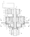
以下、図面に基づき、本発明の実施形態を説明する。図1乃至図5(a)(b)は第1の実施形態を示す。この第1実施形態のブレーキ付減速機は、図1に示すように、ハウジング(固定部材)1の内側に、減速機構2とブレーキとしての逆入力遮断機構3とを軸方向に並べて組み込んでユニット化したもので、モータ駆動によって被駆動部材を作動させる装置の駆動部に組み込まれる。
Hereinafter, embodiments of the present invention will be described with reference to the drawings. 1 to 5 (a) and 5 (b) show a first embodiment. As shown in FIG. 1, the speed reducer with brake according to the first embodiment is a unit in which a speed reduction mechanism 2 and a reverse input blocking mechanism 3 as a brake are arranged side by side in an axial direction inside a housing (fixed member) 1. It is incorporated into a drive unit of a device that operates a driven member by driving a motor.
前記ハウジング1は、減速機構2側の前半部1aと逆入力遮断機構3側の後半部1bとに分割されており、その前半部1aと後半部1bの互いの突き合わせ端にフランジ1cが形成されている。そして、両方のフランジ1cの対応する位置にあけた複数の取付孔1dを利用して、前半部1aと後半部1bとを接続するとともにハウジング1全体を装置内で固定するようになっている。
The housing 1 is divided into a front half 1a on the speed reduction mechanism 2 side and a rear half 1b on the reverse input blocking mechanism 3 side, and a flange 1c is formed at the abutting end of the front half 1a and the rear half 1b. ing. The plurality of mounting holes 1d opened at corresponding positions of both flanges 1c are used to connect the front half 1a and the rear half 1b and to fix the entire housing 1 within the apparatus.
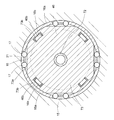
前記減速機構2は、図1および図3に示すように、入力軸4と、入力軸4の外周に嵌合固定される太陽歯車5と、太陽歯車5の径方向外側でハウジング1の前半部1aに固定される内歯車6と、太陽歯車5と内歯車6の両方に噛み合う複数の遊星歯車7と、各遊星歯車7の中心に通される支軸8aを有し、各遊星歯車7を自転可能に支持する円板状のキャリア8とからなる遊星歯車機構である。なお、入力軸4外周への太陽歯車5の嵌合固定はキーとキー溝によって行われるが(後述する他の軸と歯車の嵌合固定についても同じ)、入力軸4と太陽歯車5は一体形成してもよい。
As shown in FIGS. 1 and 3, the speed reduction mechanism 2 includes an input shaft 4, a sun gear 5 fitted and fixed to the outer periphery of the input shaft 4, and a front half of the housing 1 on the radially outer side of the sun gear 5. 1a, a plurality of planetary gears 7 meshing with both the sun gear 5 and the internal gear 6, and a support shaft 8a passed through the center of each planetary gear 7, It is a planetary gear mechanism comprising a disk-like carrier 8 that is supported so as to be able to rotate. The sun gear 5 is fitted and fixed to the outer periphery of the input shaft 4 by a key and a key groove (the same applies to fitting and fixing of other shafts and gears described later), but the input shaft 4 and the sun gear 5 are integrated. It may be formed.
この減速機構2の入力軸4は、一端側(図1の左側)がキャリア8の中心を貫通して逆入力遮断機構3側へ突出しており、他端側(図1の右側)がハウジング1の前半部1aを貫通し、軸受9を介してハウジング1に回転自在に支持されている。そして、ハウジング前半部1aからの突出部の外周に入力歯車10が嵌合固定されている。その入力歯車10は駆動モータ11の主軸12の外周に嵌合固定された伝達歯車13に噛み合っており、駆動モータ11から伝達歯車13および入力歯車10を介して入力軸4に回転が伝達されるようになっている。
The input shaft 4 of the speed reduction mechanism 2 has one end side (left side in FIG. 1) passing through the center of the carrier 8 and protruding toward the reverse input blocking mechanism 3 side, and the other end side (right side in FIG. 1) is housing 1. The first half 1a of the housing 1 is passed through the housing 1 and is rotatably supported by the housing 1 via a bearing 9. The input gear 10 is fitted and fixed to the outer periphery of the protruding portion from the housing front half 1a. The input gear 10 meshes with a transmission gear 13 fitted and fixed to the outer periphery of the main shaft 12 of the drive motor 11, and rotation is transmitted from the drive motor 11 to the input shaft 4 via the transmission gear 13 and the input gear 10. It is like that.
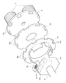
したがって、駆動モータ11を駆動すると、入力軸4が太陽歯車5と一体に回転し、各遊星歯車7が自転しながら公転することにより、キャリア8が減速されて回転する。そのキャリア8の外周部には、後述するように逆入力遮断機構3に回転を伝達するための凸部8bが周方向に等間隔で複数設けられている。すなわち、キャリア8は、減速機構2の出力側部材であると同時に逆入力遮断機構3の入力部となっている。なお、キャリア8を減速機構2の出力側部材となる部分と逆入力遮断機構3の入力部となる部分に分割して、その両者を回転伝達可能に連結するようにしてもよい。
Therefore, when the drive motor 11 is driven, the input shaft 4 rotates integrally with the sun gear 5, and each planetary gear 7 revolves while rotating, whereby the carrier 8 is decelerated and rotated. As will be described later, a plurality of convex portions 8 b for transmitting rotation to the reverse input blocking mechanism 3 are provided on the outer peripheral portion of the carrier 8 at equal intervals in the circumferential direction. That is, the carrier 8 is an output side member of the speed reduction mechanism 2 and at the same time an input portion of the reverse input blocking mechanism 3. In addition, the carrier 8 may be divided into a portion serving as an output side member of the speed reduction mechanism 2 and a portion serving as an input portion of the reverse input blocking mechanism 3, and both of them may be coupled so as to transmit rotation.
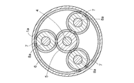
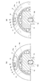
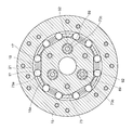
前記逆入力遮断機構3は、図1、図2および図4に示すように、上述した入力部としてのキャリア8と、図示省略した被駆動部材に回転伝達可能に連結される出力部としての出力軸14と、出力軸14の径方向外側でハウジング後半部1bの一部をなし、内周に円筒面を有する固定外輪15と、出力軸14の大径部外周面と固定外輪15の内周面との間に挿入される柱部16aが内周部に設けられた円環状のロック解除片16と、出力軸14の大径部外周面と固定外輪15の内周面との間に組み込まれるころ17およびコイルばね18を備えた逆入力遮断クラッチである。
As shown in FIGS. 1, 2 and 4, the reverse input blocking mechanism 3 is an output as an output unit connected to the carrier 8 as the input unit described above and a driven member (not shown) so as to be able to transmit rotation. A shaft 14, a fixed outer ring 15 that forms a part of the housing rear half 1 b on the radially outer side of the output shaft 14 and has a cylindrical surface on the inner periphery, a large-diameter outer peripheral surface of the output shaft 14, and an inner periphery of the fixed outer ring 15 A column portion 16a inserted between the outer peripheral surface and the annular unlocking piece 16 provided on the inner peripheral portion, and the outer peripheral surface of the large-diameter portion of the output shaft 14 and the inner peripheral surface of the fixed outer ring 15 are incorporated. The reverse input cutoff clutch includes a roller 17 and a coil spring 18.
この逆入力遮断機構3の出力軸14は、中心部に減速機構2の入力軸4の一端部が回転自在に嵌め込まれる軸受穴14aを有し、入力軸4と同心に配されている。そして、軸受19を介してハウジング1に回転自在に支持され、ハウジング後半部1bから突出する一端部の外周に嵌合固定された出力歯車20を介して前記被駆動部材に回転を出力するようになっている。
The output shaft 14 of the reverse input blocking mechanism 3 has a bearing hole 14a into which one end of the input shaft 4 of the speed reduction mechanism 2 is rotatably fitted at the center, and is arranged concentrically with the input shaft 4. Then, rotation is output to the driven member via an output gear 20 that is rotatably supported by the housing 1 via a bearing 19 and is fitted and fixed to the outer periphery of one end protruding from the housing rear half 1b. It has become.
また、出力軸14の大径部の外周には、径方向と直交する複数のカム面14bが設けられ、これらの各カム面14bと固定外輪15の内周円筒面との間に周方向両側で次第に狭小となる楔形空間21が形成されている。そして、これらの各楔形空間21には、一対のころ17が各ころ17を楔形空間21の狭小部に押し込むコイルばね18を挟んだ状態で配され、各楔形空間21の周方向両側(ころ17を挟んでコイルばね18と対向する位置)にロック解除片16の柱部16aが挿入されている。そのロック解除片16の外周部には、キャリア8の凸部8bが周方向隙間をもって挿入される第1の係合穴16bが設けられている。
A plurality of cam surfaces 14 b perpendicular to the radial direction are provided on the outer periphery of the large-diameter portion of the output shaft 14, and both sides in the circumferential direction are provided between these cam surfaces 14 b and the inner peripheral cylindrical surface of the fixed outer ring 15. Thus, a wedge-shaped space 21 that is gradually narrowed is formed. In each wedge-shaped space 21, a pair of rollers 17 are arranged in a state of sandwiching a coil spring 18 that pushes each roller 17 into a narrow portion of the wedge-shaped space 21. The column portion 16a of the unlocking piece 16 is inserted at a position facing the coil spring 18 across the coil. A first engagement hole 16 b into which the convex portion 8 b of the carrier 8 is inserted with a gap in the circumferential direction is provided on the outer peripheral portion of the unlocking piece 16.
また、出力軸14の他端部14cは断面小判形に形成されており、その外周にロック解除片16とキャリア8に挟まれるフランジ22が嵌合固定されている。そのフランジ22の外周部には、キャリア8の凸部8bがロック解除片16の第1の係合穴16bよりも広い周方向隙間をもって挿入される第2の係合穴22aが設けられている。
The other end portion 14c of the output shaft 14 is formed in an oval cross section, and a flange 22 sandwiched between the lock release piece 16 and the carrier 8 is fitted and fixed to the outer periphery thereof. A second engagement hole 22 a into which the convex portion 8 b of the carrier 8 is inserted with a wider circumferential clearance than the first engagement hole 16 b of the unlocking piece 16 is provided on the outer peripheral portion of the flange 22. .
この逆入力遮断機構3では、前記被駆動部材から出力軸14に逆入力トルクが加えられても、回転方向後側のころ17がコイルばね18の弾性力によって楔形空間21の狭小部に押し込まれているので、出力軸14が固定外輪15にロックされ、被駆動部材の位置(姿勢)は変わらない。
In the reverse input blocking mechanism 3, even when reverse input torque is applied from the driven member to the output shaft 14, the roller 17 on the rear side in the rotational direction is pushed into the narrow portion of the wedge-shaped space 21 by the elastic force of the coil spring 18. Therefore, the output shaft 14 is locked to the fixed outer ring 15, and the position (posture) of the driven member does not change.
一方、駆動モータ11が駆動されて、減速機構2の出力側部材であり逆入力遮断機構3の入力部でもあるキャリア8が回転すると、まず、図5(a)に示すように、キャリア8の凸部8bがロック解除片16の第1の係合穴16bに係合してロック解除片16を周方向に押す。これにより、ロック解除片16の柱部16aが回転方向後方側のころ17をコイルばね18の弾力に抗して楔形空間21の広大部へ押しやるので、出力軸14と固定外輪15とのロック状態が解除される。そして、図5(b)に示すように、キャリア8がさらに回転して、その凸部8bが出力軸14のフランジ22の第2の係合穴22aに係合すると、凸部8bがフランジ22を周方向に押すようになり、キャリア8の回転がフランジ22と一体の出力軸14に伝達され、出力歯車20を介して被駆動部材に出力される。
On the other hand, when the drive motor 11 is driven and the carrier 8 that is the output side member of the speed reduction mechanism 2 and also the input portion of the reverse input blocking mechanism 3 rotates, first, as shown in FIG. The convex portion 8b engages with the first engagement hole 16b of the unlocking piece 16 and pushes the unlocking piece 16 in the circumferential direction. As a result, the column portion 16a of the unlocking piece 16 pushes the roller 17 on the rear side in the rotational direction against the elastic force of the coil spring 18 to the wide portion of the wedge-shaped space 21, so that the output shaft 14 and the fixed outer ring 15 are locked. Is released. Then, as shown in FIG. 5B, when the carrier 8 further rotates and the convex portion 8 b engages with the second engagement hole 22 a of the flange 22 of the output shaft 14, the convex portion 8 b becomes the flange 22. The rotation of the carrier 8 is transmitted to the output shaft 14 integrated with the flange 22 and is output to the driven member via the output gear 20.
すなわち、この逆入力遮断機構3は、出力軸14を固定外輪15にロックするロック手段と、キャリア8(入力部)に入力トルクが加えられたときにキャリア8の回転により出力軸14と固定外輪15とのロック状態を解除するロック解除手段と、そのロック状態が解除されたときに、キャリア8の回転を僅かな角度遅れをもって出力軸14に伝達するトルク伝達手段とを備えたロック式のものである。
That is, the reverse input blocking mechanism 3 includes a lock unit that locks the output shaft 14 to the fixed outer ring 15, and the output shaft 14 and the fixed outer ring by rotation of the carrier 8 when input torque is applied to the carrier 8 (input unit). And a lock release means for releasing the locked state with the motor 15 and a torque transmitting means for transmitting the rotation of the carrier 8 to the output shaft 14 with a slight angular delay when the locked state is released. It is.
このブレーキ付減速機は、上述したように、駆動モータ11の回転を減速して被駆動部材の側へ出力する減速機構2と、駆動モータ11停止時に被駆動部材の位置を保持するブレーキとしてのロック式の逆入力遮断機構3とをユニット化したものであり、その逆入力遮断機構3は被駆動部材から加えられる逆入力トルクに対して機械的にロックするようになっているので、電力を必要としないし、装置への組み込みも容易である。したがって、このブレーキ付減速機を組み込んだ装置では、無励磁作動型電磁ブレーキと減速機を別々に組み込んだものに比べて、消費電力が少なく組立作業も効率よく行うことができる。さらに、停止中に外部から被駆動部材に加えられるトルクは逆入力遮断機構3で負荷して減速機構2に伝達しないので、減速機構2の保護機能の点でも優れたものとなっている。
As described above, the speed reducer with a brake is a reduction mechanism 2 that decelerates the rotation of the drive motor 11 and outputs it to the driven member side, and a brake that holds the position of the driven member when the drive motor 11 stops. The lock type reverse input blocking mechanism 3 is unitized, and the reverse input blocking mechanism 3 is mechanically locked against the reverse input torque applied from the driven member. It is not necessary and can be easily incorporated into the device. Therefore, the apparatus incorporating the speed reducer with a brake consumes less power and can perform the assembly work more efficiently than the apparatus incorporating the non-excitation operation type electromagnetic brake and the speed reducer separately. Further, since the torque applied to the driven member from the outside during the stop is loaded by the reverse input blocking mechanism 3 and is not transmitted to the speed reduction mechanism 2, the protection function of the speed reduction mechanism 2 is also excellent.
また、逆入力遮断機構3では、その入力部となるキャリア8の凸部8bが、ロック解除片16の第1の係合穴16bと出力軸14のフランジ22の第2の係合穴22aに周方向隙間をもって挿入されており、各係合穴16b、22aに順に係合することによってロック解除とその後の回転伝達を行うようになっているので、各係合穴16b、22aと凸部8bの周方向隙間を適切に設計することにより、確実にロック解除された状態で回転伝達が行われ、かつロック解除からトルク伝達開始までの時間遅れの少ないものとすることができる。
Further, in the reverse input blocking mechanism 3, the convex portion 8 b of the carrier 8 serving as the input portion is formed in the first engagement hole 16 b of the lock release piece 16 and the second engagement hole 22 a of the flange 22 of the output shaft 14. Since it is inserted with a clearance in the circumferential direction and is engaged with each engagement hole 16b, 22a in order to perform unlocking and subsequent rotation transmission, each engagement hole 16b, 22a and projection 8b By appropriately designing the circumferential clearance, rotation transmission can be performed in a state where the lock is reliably released, and the time delay from the unlocking to the start of torque transmission can be reduced.
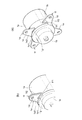
図6および図7(a)、(b)は逆入力遮断機構3のトルク伝達手段の変形例を示す。この変形例では、入力軸4の一端部を短縮してキャリア8の入力側面中央の軸受穴8cに回転自在に嵌め込み、キャリア8の出力側端面中央に断面小判形の回転伝達軸8dを設けている。また、出力軸14は、断面小判形の他端部14cおよびフランジ22をなくし、入力軸4の一端部が嵌め込まれる軸受穴14aに代えてキャリア8の回転伝達軸8dが挿入される第3の係合穴14dを設けている。その第3の係合穴14dは、回転伝達軸8dとほぼ同形状であるが、回転伝達軸8dの平面部と対向する係合面が凸形に形成されている。
6 and 7 (a) and 7 (b) show modifications of the torque transmission means of the reverse input blocking mechanism 3. FIG. In this modification, one end portion of the input shaft 4 is shortened and is rotatably fitted in a bearing hole 8c at the center of the input side surface of the carrier 8, and a rotation transmission shaft 8d having an oval cross section is provided at the center of the output side end surface of the carrier 8. Yes. Further, the output shaft 14 has the other end portion 14c having an oval cross section and the flange 22, and the rotation transmission shaft 8d of the carrier 8 is inserted in place of the bearing hole 14a into which the one end portion of the input shaft 4 is fitted. An engagement hole 14d is provided. The third engagement hole 14d has substantially the same shape as the rotation transmission shaft 8d, but the engagement surface facing the flat portion of the rotation transmission shaft 8d is formed in a convex shape.
したがって、駆動モータ11が駆動されてキャリア8が回転すると、図7(b)に示すように、キャリア8の凸部8bがロック解除片16の第1の係合穴16bに係合してロック解除片16を周方向に押すことにより、出力軸14と固定外輪15とのロック状態が解除された後、キャリア8がさらに回転することによって、回転伝達軸8dの平面部が出力軸14の第3の係合穴14dの凸形の係合面の半分に面接触する状態で係合し、キャリア8の回転が出力軸14に伝達される。この変形例を採用すれば、図1乃至図5(a)(b)で説明した例に比べて、ロック解除からトルク伝達開始までの時間を短くすることは難しくなるが、部品数が削減でき組み立てやすくなる。
Therefore, when the drive motor 11 is driven and the carrier 8 rotates, the convex portion 8b of the carrier 8 engages with the first engagement hole 16b of the unlocking piece 16 and locks as shown in FIG. By pushing the release piece 16 in the circumferential direction, the locked state between the output shaft 14 and the fixed outer ring 15 is released, and then the carrier 8 further rotates, so that the plane portion of the rotation transmission shaft 8d is moved to the first position of the output shaft 14. 3 is engaged with the half of the convex engagement surface of the engagement hole 14 d in a surface contact state, and the rotation of the carrier 8 is transmitted to the output shaft 14. If this modification is adopted, it will be difficult to shorten the time from unlocking to the start of torque transmission compared to the example described in FIGS. 1 to 5A and 5B, but the number of parts can be reduced. Easy to assemble.
図8および図9(a)、(b)は、逆入力遮断機構3に対し、上述したトルク伝達手段の変形に加えてロック解除手段の変形を行った例を示す。この変形例は、図6および図7(a)(b)で示した例をベースとし、キャリア8の凸部8bをなくすとともに、ロック解除片16として、外周部に柱部16aを有し第1の係合穴16bが形成されていない円板状のものを採用し、このロック解除片16をキャリア8の断面小判形の回転伝達軸8dの外周に嵌合固定している。
8 and 9 (a) and 9 (b) show an example in which the lock release means is deformed in addition to the above-described deformation of the torque transmission means for the reverse input blocking mechanism 3. FIG. This modification is based on the example shown in FIG. 6 and FIGS. 7A and 7B, eliminates the convex portion 8b of the carrier 8, and has a column portion 16a on the outer peripheral portion as the unlocking piece 16. A disc-shaped member in which one engagement hole 16b is not formed is adopted, and the lock release piece 16 is fitted and fixed to the outer periphery of a rotation transmission shaft 8d having a small cross-sectional shape of the carrier 8.
したがって、駆動モータ11が駆動されてキャリア8が回転すると、キャリア8の回転伝達軸8dと一体にロック解除片16が回転し、その柱部16aが回転方向後方側のころ17を押してロック状態の解除を行う。その後の回転伝達軸8dから出力軸14への回転伝達については、図6、7(a)(b)の例と同じである。この変形例を採用すれば、図6、7(a)(b)の例よりも、キャリア8およびロック解除片16の構造が簡単になり、製造しやすくなる。
Therefore, when the drive motor 11 is driven and the carrier 8 rotates, the unlocking piece 16 rotates integrally with the rotation transmission shaft 8d of the carrier 8, and the column portion 16a pushes the roller 17 on the rear side in the rotation direction to lock the carrier. Release. Subsequent rotation transmission from the rotation transmission shaft 8d to the output shaft 14 is the same as the example of FIGS. If this modification is adopted, the structure of the carrier 8 and the unlocking piece 16 becomes simpler and easier to manufacture than in the examples of FIGS.
図10(a)(b)および図11(a)(b)は、ハウジング1の組立手段の変形例を示す。この変形例のハウジング1は、図10(a)、(b)に示すように、前半部1aと後半部1bの互いの突き合わせ端に、フランジ1cに代わる取付片1e、1fを、同じものがハウジング1の中心を挟んで対向するように2つずつ設けている。
FIGS. 10A and 10B and FIGS. 11A and 11B show modified examples of the assembly means of the housing 1. As shown in FIGS. 10 (a) and 10 (b), the housing 1 of this modification is provided with the same mounting pieces 1e and 1f instead of the flange 1c at the butting ends of the front half 1a and the rear half 1b. Two are provided so as to face each other across the center of the housing 1.
前半部1aの取付片1eは、前半部1aの突き合わせ端から径方向に延びる基部1e1と、基部1e1の先端から径方向に張り出す略三角板状の本体部1e2とからなり、本体部1e2と突き合わせ端との間に切れ込み1gが形成されている。一方、後半部1bの取付片1fは、後半部1bの突き合わせ端から軸方向に延びる基部1f1と、基部1f1の先端から径方向に張り出す略三角板状の本体部1f2とからなり、本体部1f2と突き合わせ端との間に切れ込み1hが形成されている。その基部1f1と切れ込み1hの周方向の位置関係は、前半部1aの取付片1eの基部1e1と切れ込み1gの周方向位置関係と逆になっている。また、各取付片1e、1fの本体部1e2、1f2には取付孔1dがあけられている。
The mounting piece 1e of the front half 1a is composed of a base 1e1 extending in the radial direction from the abutting end of the front half 1a, and a substantially triangular plate-shaped main body 1e2 projecting in the radial direction from the tip of the base 1e1. A notch 1g is formed between the ends. On the other hand, the mounting piece 1f of the rear half 1b is composed of a base 1f1 extending in the axial direction from the butted end of the rear half 1b and a substantially triangular plate-like main body 1f2 projecting radially from the tip of the base 1f1. A cut 1h is formed between the end and the butted end. The positional relationship in the circumferential direction between the base portion 1f1 and the notch 1h is opposite to the circumferential positional relationship between the base portion 1e1 of the mounting piece 1e of the front half 1a and the notch 1g. Further, mounting holes 1d are formed in the main body portions 1e2, 1f2 of the mounting pieces 1e, 1f.
なお、前半部1aおよび後半部1bは、各取付片1e、1fの基部1e1、1f1の周方向両側にスリットが入れられている。これにより、取付片1e、1fを曲げ加工によって形成したときに基部1e1、1f1が端面から軸方向にはみ出さず、前半部1aと後半部1bの端面どうしを隙間なく突き合わせられるようになっている。
The front half 1a and the rear half 1b have slits on both sides in the circumferential direction of the bases 1e1 and 1f1 of the mounting pieces 1e and 1f. Thereby, when the attachment pieces 1e and 1f are formed by bending, the base portions 1e1 and 1f1 do not protrude from the end surface in the axial direction, and the end surfaces of the front half portion 1a and the rear half portion 1b can be abutted with each other without any gap. .
このハウジング1の組立方法は、図11(a)に示すように、前半部1aと後半部1bとを、それぞれの取付片1e、1fが軸方向に重ならない状態で互いに突き合わせた後、取付片1e、1fの切れ込み1g、1hどうしが近づく方向に相対回転させる(図では後半部1bのみ回転)。これにより、図11(b)に示すように、一方の取付片1eの切れ込み1gに他方の取付片1fの基部1f1が入り込み、他方の取付片1fの切れ込み1hに一方の取付片1eの基部1e1が入り込んで、両取付片1e、1fが軸方向に重なる状態で噛み合い、前半部1aと後半部1bとが軸方向に一体化される。このとき、両取付片1e、1fの取付孔1dも重なるようになっているので、その取付孔1dを利用して、一体化した前半部1aと後半部1bを装置内で固定すればよい。
As shown in FIG. 11 (a), the housing 1 is assembled by attaching the front half 1a and the rear half 1b to each other in such a manner that the mounting pieces 1e and 1f do not overlap each other in the axial direction. 1e, 1f cuts 1g, 1h are relatively rotated in the direction in which they approach each other (in the figure, only the latter half 1b is rotated). Accordingly, as shown in FIG. 11B, the base 1f1 of the other mounting piece 1f enters the cut 1g of the one mounting piece 1e, and the base 1e1 of the one mounting piece 1e enters the cut 1h of the other mounting piece 1f. Enters, the both attachment pieces 1e, 1f are engaged with each other in the axial direction, and the front half 1a and the rear half 1b are integrated in the axial direction. At this time, since the mounting holes 1d of both the mounting pieces 1e and 1f are also overlapped, the integrated front half 1a and rear half 1b may be fixed in the apparatus using the mounting holes 1d.
上述したハウジング1組立手段の変形例を用いれば、ハウジング1の前半部1aと後半部1bを一体化させた状態で保管や運搬を行えるようになり、図1乃至図9(a)(b)に示した例に比べて取扱いがしやすくなる。また、ハウジング組立手段の別の変形例として、図1乃至図9(a)(b)に示した例に対し、前半部と後半部のフランジの一方に設けた切欠きの縁部に、他方に設けた爪を掛けるようにしたものも考えられるが、その場合には前半部と後半部を一体化させる際に爪を折り曲げる必要がある。これに対し、上述した変形例では、前半部1aと後半部1bを相対回転させるだけで一体化させることができ、ハウジング1組立時に手間がかからないし、組立後の分解も容易なためリユースしやすいという利点がある。
If the modified example of the housing 1 assembling means described above is used, the housing 1 can be stored and transported with the front half 1a and the latter half 1b being integrated, and FIGS. 1 to 9 (a) (b). It is easier to handle than the example shown in. Further, as another modification of the housing assembly means, in contrast to the example shown in FIGS. 1 to 9 (a) and 9 (b), the other edge of the notch provided on one of the flanges of the front half and the rear half is provided on the other side. In this case, it is necessary to bend the nail when the first half and the second half are integrated. On the other hand, in the above-described modified example, the front half 1a and the rear half 1b can be integrated by simply rotating relative to each other, and it is not time-consuming at the time of assembling the housing 1, and it is easy to disassemble after assembly so that it can be easily reused. There is an advantage.
なお、図10(a)(b)および図11(a)(b)の例では、前半部1aに径方向に延びる基部1e1を有する取付片1eを設け、後半部1bに軸方向に延びる基部1f1を有する取付片1fを設けたが、これと逆になるように両取付片1e、1fを設けてもよい。また、このハウジング組立手段の変形例は、減速機構単体の減速機や、逆入力遮断クラッチ等のハウジングにも広く応用することができる。そして、一体化される部材の一方が蓋状のものである場合は、その蓋状部材には前述のスリットを設ける必要がなくなり、加工が簡単になる。
10A, 10B, and 11A, 11B, an attachment piece 1e having a base 1e1 extending in the radial direction is provided in the front half 1a, and a base extending in the axial direction is provided in the rear half 1b. Although the attachment piece 1f having 1f1 is provided, both attachment pieces 1e and 1f may be provided so as to be reversed. Moreover, the modified example of the housing assembly means can be widely applied to a speed reducer with a single speed reduction mechanism, a housing such as a reverse input cutoff clutch, and the like. When one of the members to be integrated is a lid-like member, it is not necessary to provide the aforementioned slit in the lid-like member, and processing is simplified.
図12は第2の実施形態を示す。この実施形態では、第1実施形態の減速機構2に代えて、2つの遊星歯車機構(第1遊星歯車機構31と第2遊星歯車機構41)を軸方向に並べて組み込んだ差動式の減速機構23を採用したものである。また、それに合わせて駆動モータ11から減速機構23までの構成を変更し、その変更部分を覆うようにハウジング1の前半部1aも変更している。ブレーキとしての逆入力遮断機構3の構成は、第1実施形態と同じである。
FIG. 12 shows a second embodiment. In this embodiment, instead of the speed reduction mechanism 2 of the first embodiment, a differential speed reduction mechanism in which two planetary gear mechanisms (a first planetary gear mechanism 31 and a second planetary gear mechanism 41) are incorporated side by side in the axial direction. 23 is adopted. Moreover, the structure from the drive motor 11 to the speed reduction mechanism 23 is changed according to it, and the front half part 1a of the housing 1 is also changed so that the changed part may be covered. The configuration of the reverse input blocking mechanism 3 as a brake is the same as that of the first embodiment.
前記第1遊星歯車機構31は、円筒状の第1入力軸32と、第1入力軸32に一体に形成された第1太陽歯車33と、第1太陽歯車33の径方向外側に配される第1内歯車34と、第1太陽歯車33と第1内歯車34の両方に噛み合う複数の第1遊星歯車35と、各第1遊星歯車35の中心に通される支軸36aを有し、各第1遊星歯車35を自転可能に支持する第1キャリア36とからなる。その第1キャリア36はハウジング前半部1aと一体に形成されている。また、第1入力軸32は、第1キャリア36の中心を貫通して、第1キャリア36に軸受37を介して回転自在に支持されており、第1キャリア36からの突出部の外周に第1入力歯車24が嵌合固定されている。
The first planetary gear mechanism 31 is arranged on a radially outer side of the first input shaft 32 having a cylindrical shape, a first sun gear 33 formed integrally with the first input shaft 32, and the first sun gear 33. A first internal gear 34; a plurality of first planetary gears 35 that mesh with both the first sun gear 33 and the first internal gear 34; and a support shaft 36a that passes through the center of each first planetary gear 35; It consists of a first carrier 36 that supports each first planetary gear 35 so that it can rotate. The first carrier 36 is formed integrally with the housing front half 1a. The first input shaft 32 passes through the center of the first carrier 36 and is rotatably supported by the first carrier 36 via a bearing 37. The first input shaft 32 is provided on the outer periphery of the protruding portion from the first carrier 36. One input gear 24 is fitted and fixed.
前記第2遊星歯車機構41は、第1遊星歯車機構31の第1入力軸32を回転可能に貫通する第2入力軸42と、第1入力軸32の一端から突出する第2入力軸42の突出部に一体に形成された第2太陽歯車43と、第1内歯車34と一体に形成され、第2太陽歯車43の径方向外側に配される第2内歯車44と、第2太陽歯車43と第2内歯車44の両方に噛み合う複数の第2遊星歯車45と、各第2遊星歯車45の中心に通される支軸46aを有し、各第2遊星歯車45を自転可能に支持する第2キャリア46とからなる。その第2キャリア46は、第1実施形態のキャリア8と同じく、逆入力遮断機構3に回転を伝達するための複数の凸部46bが設けられている。
The second planetary gear mechanism 41 includes a second input shaft 42 that rotatably penetrates the first input shaft 32 of the first planetary gear mechanism 31 and a second input shaft 42 that protrudes from one end of the first input shaft 32. A second sun gear 43 formed integrally with the projecting portion, a second internal gear 44 formed integrally with the first internal gear 34 and arranged radially outside the second sun gear 43, and a second sun gear And a plurality of second planetary gears 45 meshing with both the second planetary gears 44 and a support shaft 46a that passes through the center of each of the second planetary gears 45, and supports the second planetary gears 45 so that they can rotate. And the second carrier 46. Similar to the carrier 8 of the first embodiment, the second carrier 46 is provided with a plurality of convex portions 46 b for transmitting rotation to the reverse input blocking mechanism 3.
この第2遊星歯車機構41の第2入力軸42は、第1実施形態の入力軸4と同様に、一端部がキャリア36の中心を貫通して逆入力遮断機構3の出力軸14の軸受穴14aに回転自在に嵌め込まれている。そして、第1入力軸32他端からの突出部の外周に第2入力歯車25が嵌合固定され、他端部が軸受47を介してハウジング1に回転自在に支持されている。また、第2太陽歯車43と隣接する位置に、第1遊星歯車機構31と第2遊星歯車機構41の遊星歯車35、45どうしの接触を防止するための円板状のスペーサ26が嵌合固定されている。
Similarly to the input shaft 4 of the first embodiment, the second input shaft 42 of the second planetary gear mechanism 41 has one end passing through the center of the carrier 36 and a bearing hole of the output shaft 14 of the reverse input blocking mechanism 3. 14a is rotatably fitted. The second input gear 25 is fitted and fixed to the outer periphery of the projecting portion from the other end of the first input shaft 32, and the other end is rotatably supported by the housing 1 via a bearing 47. A disc-like spacer 26 for preventing contact between the planetary gears 35 and 45 of the first planetary gear mechanism 31 and the second planetary gear mechanism 41 is fitted and fixed at a position adjacent to the second sun gear 43. Has been.
前記第1遊星歯車機構31と第2遊星歯車機構41の各部の歯車仕様は同一であり、第1入力歯車24と第2入力歯車25の歯車仕様は異なっている。そして、駆動モータ11の主軸12には、一端部を第1キャリア36に回転自在に支持された駆動軸27が連結されており、この駆動軸27の外周に嵌合固定された第1伝達歯車28および第2伝達歯車29に、第1入力歯車24および第2入力歯車25がそれぞれ噛み合っている。これにより、駆動モータ11から各伝達歯車28、29および各入力歯車24、25を介して各入力軸32、42に回転が伝達され、第1入力軸32と第2入力軸42に互いに異なる回転数の回転が同時に入力されるようになっている。
The gear specifications of the respective parts of the first planetary gear mechanism 31 and the second planetary gear mechanism 41 are the same, and the gear specifications of the first input gear 24 and the second input gear 25 are different. A drive shaft 27 having one end rotatably supported by the first carrier 36 is connected to the main shaft 12 of the drive motor 11, and a first transmission gear fitted and fixed to the outer periphery of the drive shaft 27. The first input gear 24 and the second input gear 25 mesh with the 28 and the second transmission gear 29, respectively. As a result, rotation is transmitted from the drive motor 11 to the input shafts 32 and 42 via the transmission gears 28 and 29 and the input gears 24 and 25, and the first input shaft 32 and the second input shaft 42 have different rotations. A number of rotations are entered simultaneously.
この減速機構23の動作は、まず、駆動モータ11の駆動により、上述のように第1入力軸32と第2入力軸42とが互いに異なる回転数で回転する。このとき、第1遊星歯車機構31では、第1キャリア36が固定されているため、第1遊星歯車35が公転を拘束された状態で自転して、第1内歯車34を第1入力軸32と逆の方向に回転させる。そして、第2遊星歯車機構41では、第2内歯車44が第1内歯車34と一体に回転するので、第2遊星歯車45が自転しながら第1入力軸32と第2入力軸42の回転数の差に応じた分だけ公転し、この第2遊星歯車45の公転により第2キャリア46が回転して、第1実施形態と同様に逆入力遮断機構3のロック解除と出力軸14への回転伝達が行われる。
In the operation of the speed reduction mechanism 23, first, the drive motor 11 drives the first input shaft 32 and the second input shaft 42 to rotate at different rotational speeds as described above. At this time, in the first planetary gear mechanism 31, since the first carrier 36 is fixed, the first planetary gear 35 rotates in a state in which the revolution is restrained, and the first internal gear 34 is moved to the first input shaft 32. Rotate in the opposite direction. In the second planetary gear mechanism 41, since the second internal gear 44 rotates integrally with the first internal gear 34, the rotation of the first input shaft 32 and the second input shaft 42 while the second planetary gear 45 rotates. The second carrier 46 rotates by the revolution of the second planetary gear 45 according to the difference in number, and the reverse input blocking mechanism 3 is unlocked and the output shaft 14 is released as in the first embodiment. Rotational transmission is performed.
この第2実施形態では、上述した差動式の減速機構23を採用しているので、第1入力軸32と第2入力軸42の回転数の差に応じた非常に高い減速率が得られる。しかも、両遊星歯車機構31、41の歯車仕様が同一なので、各遊星歯車機構31、41の歯車設計や部品製作を効率よく行うことができる。
In the second embodiment, since the differential reduction mechanism 23 described above is employed, a very high reduction rate according to the difference in the rotational speed between the first input shaft 32 and the second input shaft 42 can be obtained. . In addition, since the gear specifications of the planetary gear mechanisms 31 and 41 are the same, the gear design and parts manufacture of the planetary gear mechanisms 31 and 41 can be performed efficiently.
さらに、減速機構23の入力側部材となる駆動軸27のハウジング前半部1aからの突出部の外周には円板状の手動操作部30が嵌合固定されており、駆動モータ11を停止させてメンテナンス等を行う際に、必要に応じて手動操作部30を回転させて被駆動部材の位置(姿勢)を変えられるようになっている。なお、手動操作部30の位置は、図中の一点鎖線で示すように、主軸12を駆動モータ11から減速機構23と対向する側と反対の側に突出させて、その端部に手動操作部30を取り付けるようにしてもよいし、図中の二点鎖線で示すように、駆動軸27、第1伝達歯車28および第2伝達歯車29をもう一組設け、その駆動軸27の他端部に手動操作部30を取り付けるようにしてもよい。
Further, a disk-like manual operation portion 30 is fitted and fixed to the outer periphery of the protruding portion from the housing front half portion 1a of the drive shaft 27 serving as the input side member of the speed reduction mechanism 23, and the drive motor 11 is stopped. When performing maintenance or the like, the position (posture) of the driven member can be changed by rotating the manual operation unit 30 as necessary. The position of the manual operation unit 30 is, as indicated by the alternate long and short dash line in the figure, by projecting the main shaft 12 from the drive motor 11 to the side opposite to the side facing the speed reduction mechanism 23 and at the end of the manual operation unit 30. 30, or as shown by a two-dot chain line in the figure, another set of drive shaft 27, first transmission gear 28 and second transmission gear 29 is provided, and the other end of the drive shaft 27 is provided. Alternatively, the manual operation unit 30 may be attached.
ここで、上記のように手動操作部30を駆動軸27や駆動モータ11の主軸12に取り付けていても、ブレーキが従来の無励磁作動型電磁ブレーキであると、ブレーキに通電してブレーキを解除してから手動操作部を回転させるか、あるいはブレーキがかかった状態でそのブレーキ力を上回るトルクを加えて手動操作部を回転させる必要があるが、本発明ではブレーキとしてロック式の逆入力遮断機構3を採用しているので、ブレーキがかかった安全な状態で楽に手動操作部30を回転させて被駆動部材の位置を変えることできる。
Here, even if the manual operation unit 30 is attached to the drive shaft 27 or the main shaft 12 of the drive motor 11 as described above, if the brake is a conventional non-excitation operation type electromagnetic brake, the brake is energized to release the brake. After that, it is necessary to rotate the manual operation unit or to apply a torque exceeding the braking force in a state where the brake is applied, and to rotate the manual operation unit. 3 is adopted, the position of the driven member can be changed by easily rotating the manual operation unit 30 in a safe state where the brake is applied.
また、前記手動操作部30は、駆動軸27(または駆動モータ11の主軸12)に対してねじ等により脱着可能となっている。これにより、通常のモータ駆動時には手動操作部30を取り外すようにして、運転中に必要となるスペースを縮小することができる。
The manual operation unit 30 can be attached to and detached from the drive shaft 27 (or the main shaft 12 of the drive motor 11) with a screw or the like. Thereby, the space required during operation can be reduced by removing the manual operation unit 30 during normal motor driving.
図13は第3の実施形態を示す。この実施形態では、第1実施形態の減速機構2に代えて、2つの遊星歯車機構51、61を2段に組み込んだ減速機構50を採用したものであり、その減速機構50を覆うようにハウジング1の前半部1aも変更している。ブレーキとしての逆入力遮断機構3の構成は、第1実施形態と同じである。
FIG. 13 shows a third embodiment. In this embodiment, instead of the speed reduction mechanism 2 of the first embodiment, a speed reduction mechanism 50 in which two planetary gear mechanisms 51 and 61 are incorporated in two stages is adopted, and a housing is provided so as to cover the speed reduction mechanism 50. The first half 1a of 1 is also changed. The configuration of the reverse input blocking mechanism 3 as a brake is the same as that of the first embodiment.
1段目の遊星歯車機構51は、駆動モータ主軸12および太陽歯車53と一体に形成された入力軸52と、太陽歯車53の径方向外側でハウジング前半部1aに固定される内歯車54と、太陽歯車53と内歯車54の両方に噛み合う複数の遊星歯車55と、各遊星歯車55の中心に通される支軸56aを有し、各遊星歯車55を自転可能に支持するキャリア56とからなる。
The first-stage planetary gear mechanism 51 includes an input shaft 52 formed integrally with the drive motor main shaft 12 and the sun gear 53, an internal gear 54 fixed to the housing first half 1a on the radially outer side of the sun gear 53, A plurality of planetary gears 55 meshing with both the sun gear 53 and the internal gear 54, and a carrier 56 having a support shaft 56a passed through the center of each planetary gear 55 and supporting each planetary gear 55 in a rotatable manner. .
2段目の遊星歯車機構61は、1段目のキャリア56および太陽歯車63と一体に形成された入力軸62と、太陽歯車63の径方向外側でハウジング前半部1aに固定される内歯車64と、太陽歯車63と内歯車64の両方に噛み合う複数の遊星歯車65と、各遊星歯車65の中心に通される支軸66aを有し、各遊星歯車65を自転可能に支持するキャリア66とからなる。
The second stage planetary gear mechanism 61 includes an input shaft 62 formed integrally with the first stage carrier 56 and the sun gear 63, and an internal gear 64 fixed to the housing front half 1a on the radially outer side of the sun gear 63. A plurality of planetary gears 65 meshing with both the sun gear 63 and the internal gear 64, and a support shaft 66a that passes through the center of each planetary gear 65, and a carrier 66 that supports each planetary gear 65 in a rotatable manner. Consists of.
2段目のキャリア66は、第1実施形態のキャリア8と同じく、逆入力遮断機構3に回転を伝達するための複数の凸部66bが設けられるとともに、一端面から突出する突軸部66cが逆入力遮断機構3の出力軸14の軸受穴14aに回転自在に嵌め込まれている。そして、この2段目のキャリア66の他端側中心部に2段目の入力軸62の一端部が回転自在に嵌め込まれ、この入力軸62(1段目のキャリア56)の他端側中心部に1段目の入力軸52の一端部が回転自在に嵌め込まれている。これにより、駆動モータ11の回転が2段に減速されて2段目のキャリア66に伝達されたうえで、第1実施形態と同様に、逆入力遮断機構3のロック解除と2段目のキャリア66から出力軸14への回転伝達が行われるようになっている。
Similarly to the carrier 8 of the first embodiment, the second-stage carrier 66 is provided with a plurality of convex portions 66b for transmitting rotation to the reverse input blocking mechanism 3, and a protruding shaft portion 66c protruding from one end surface. The reverse input blocking mechanism 3 is rotatably fitted in the bearing hole 14a of the output shaft 14. Then, one end of the second stage input shaft 62 is rotatably fitted in the center of the other end of the second stage carrier 66, and the other end side center of the input shaft 62 (first stage carrier 56) is fitted. One end of the first-stage input shaft 52 is rotatably fitted in the part. As a result, the rotation of the drive motor 11 is decelerated to the second stage and transmitted to the second stage carrier 66, and then the reverse input blocking mechanism 3 is unlocked and the second stage carrier, as in the first embodiment. The rotation transmission from 66 to the output shaft 14 is performed.
また、駆動モータ11の主軸12は駆動モータ11から減速機構50と対向する側と反対の側にも突出しており、その端部に手動操作部67が取り付けられている。これにより、第2実施形態と同様に、駆動モータ11を停止させてメンテナンス等を行う際に、必要に応じて手動操作部67を回転させて被駆動部材の位置(姿勢)を変えることができる。
The main shaft 12 of the drive motor 11 also protrudes from the drive motor 11 to the side opposite to the side facing the speed reduction mechanism 50, and a manual operation unit 67 is attached to the end thereof. Thus, as in the second embodiment, when the drive motor 11 is stopped and maintenance is performed, the manual operation unit 67 can be rotated as necessary to change the position (posture) of the driven member. .
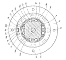
図14乃至図17(a)(b)は第4の実施形態を示す。この実施形態は、第2実施形態の逆入力遮断機構3および差動式の減速機構23等の構成の一部を変更したものである。そこで、第2実施形態と同じ機能の部材については同じ符号を付けて説明を省略し、以下では主として第2実施形態との相違点について説明する。
FIGS. 14 to 17 (a) and 17 (b) show a fourth embodiment. This embodiment is obtained by changing a part of the configuration of the reverse input blocking mechanism 3 and the differential reduction mechanism 23 of the second embodiment. Therefore, members having the same functions as those of the second embodiment are denoted by the same reference numerals and description thereof is omitted, and differences from the second embodiment will be mainly described below.
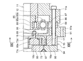
この第4実施形態では、図14に示すように、外周面に段差のないハウジング71を使用して、その前半部71aに駆動モータ11を組み込み、後半部71bに減速機構23および逆入力遮断機構3を組み込んでいる。そのハウジング前半部71aには蓋部の中心部から軸方向内側へ延びる内筒部71cが設けられており、後半部71bの出力側の端部は逆入力遮断機構3の固定外輪15として別体に形成されている。また、減速機構23の第1遊星歯車機構31と第2遊星歯車機構41は共通の入力軸72を有するものとし、逆入力遮断機構3の出力部は、固定外輪15の内周面と対向するカム部材73とその軸方向外側面に固定される出力軸74とに分割されている。そのカム部材73と出力軸74には、両者を一体化するためのねじ穴が設けられている。
In the fourth embodiment, as shown in FIG. 14, a housing 71 having no step on the outer peripheral surface is used, the drive motor 11 is incorporated in the front half 71a, and the speed reduction mechanism 23 and the reverse input blocking mechanism are installed in the rear half 71b. 3 is incorporated. The front half portion 71a of the housing is provided with an inner cylinder portion 71c extending inward in the axial direction from the center portion of the lid portion, and the output side end portion of the rear half portion 71b is separately provided as a fixed outer ring 15 of the reverse input blocking mechanism 3. Is formed. Further, the first planetary gear mechanism 31 and the second planetary gear mechanism 41 of the speed reduction mechanism 23 have a common input shaft 72, and the output portion of the reverse input blocking mechanism 3 faces the inner peripheral surface of the fixed outer ring 15. The cam member 73 is divided into an output shaft 74 that is fixed to the outer surface in the axial direction. The cam member 73 and the output shaft 74 are provided with screw holes for integrating them.
そして、減速機構23の入力軸72および逆入力遮断機構3の出力軸74はハウジング71の内筒部71cと同じ内径を有する中空軸とされ、ハウジング内筒部71c、入力軸72および出力軸74の内側に駆動モータ11を制御するためのケーブル(図示省略)等を通せるようになっている。
The input shaft 72 of the speed reduction mechanism 23 and the output shaft 74 of the reverse input blocking mechanism 3 are hollow shafts having the same inner diameter as the inner cylinder portion 71c of the housing 71, and the housing inner cylinder portion 71c, the input shaft 72, and the output shaft 74. A cable (not shown) for controlling the drive motor 11 can be passed through the inside.
前記減速機構23は、入力軸72のハウジング内筒部1cと軸方向で隣接する部位の外周に入力歯車75が嵌合固定され、この入力歯車75が駆動モータ11の主軸12の外周に嵌合固定された伝達歯車76と噛み合うことにより、駆動モータ11から回転を入力されるようになっている。その伝達歯車76には、入力歯車75よりも歯数の少ないもの(小径のもの)が用いられる。
In the speed reduction mechanism 23, an input gear 75 is fitted and fixed to the outer periphery of a portion of the input shaft 72 that is adjacent to the housing inner cylindrical portion 1 c in the axial direction. The rotation is input from the drive motor 11 by meshing with the fixed transmission gear 76. As the transmission gear 76, one having a smaller number of teeth (smaller diameter) than the input gear 75 is used.
そして、第1太陽歯車33が入力軸72の外周に嵌合固定され、第2太陽歯車43が入力軸72と一体に形成されている点、第1内歯車34と第2内歯車44とが異なる歯車仕様で形成されている点、および第1遊星歯車35がその中心から突出する軸部35aをハウジング71と一体の第1キャリア36に自転可能に支持されている点が、第2実施形態と異なっている。
The first sun gear 33 is fitted and fixed to the outer periphery of the input shaft 72, the second sun gear 43 is formed integrally with the input shaft 72, the first internal gear 34 and the second internal gear 44 are The second embodiment is that the first planetary gear 35 is supported by a first carrier 36 that is integral with the housing 71 so that the first planetary gear 35 protrudes from the center of the first planetary gear 35 so as to rotate. Is different.
この減速機構23では、駆動モータ11を駆動すると、その回転が伝達歯車76および入力歯車75を介して入力軸72に入力され、入力軸72と第1太陽歯車33および第2太陽歯車43が一体に回転する。すると、第1遊星歯車機構31では、第1キャリア36が固定されているため、第1遊星歯車35が公転を拘束された状態で自転して、第1内歯車34を入力軸72と逆の方向に回転させる。そして、第2遊星歯車機構41では、第2内歯車44が第1内歯車34と一体に回転するので、第2遊星歯車45が第2太陽歯車43と第2内歯車44との回転速度差に応じて自転しながら公転し、この第2遊星歯車45の公転が第2キャリア46を介して出力側へ伝達される。
In the reduction mechanism 23, when the drive motor 11 is driven, the rotation is input to the input shaft 72 via the transmission gear 76 and the input gear 75, and the input shaft 72, the first sun gear 33, and the second sun gear 43 are integrated. Rotate to. Then, in the first planetary gear mechanism 31, since the first carrier 36 is fixed, the first planetary gear 35 rotates in a state where the revolution is restrained, and the first internal gear 34 is opposite to the input shaft 72. Rotate in the direction. In the second planetary gear mechanism 41, the second internal gear 44 rotates integrally with the first internal gear 34, so that the second planetary gear 45 rotates between the second sun gear 43 and the second internal gear 44. Accordingly, the revolution of the second planetary gear 45 is transmitted to the output side via the second carrier 46.
したがって、第2実施形態と同様に、2つの遊星歯車機構31、41による差動運動を利用した高い減速率が得られるうえ、駆動モータ11の回転が伝達歯車76および入力歯車75を介して減速されて入力軸72に入力されるようになっているので、第2実施形態よりも各遊星歯車35、45の自転速度が抑えられる。これにより、第1遊星歯車35の軸部35aと第1キャリア36との間に配される軸受(図示省略)、および第2遊星歯車45と第2キャリア46の支軸46aとの間に配される軸受(図示省略)の寿命延長が図れ、長期間安定して使用することができる。
Therefore, as in the second embodiment, a high reduction rate using the differential motion by the two planetary gear mechanisms 31 and 41 is obtained, and the rotation of the drive motor 11 is reduced via the transmission gear 76 and the input gear 75. Thus, the rotation speed of each planetary gear 35, 45 can be suppressed as compared with the second embodiment. As a result, a bearing (not shown) disposed between the shaft portion 35a of the first planetary gear 35 and the first carrier 36, and a shaft 46a of the second planetary gear 45 and the second carrier 46 are disposed. The life of the bearing (not shown) can be extended and can be used stably for a long time.
また、図14の例では、駆動モータ11をハウジング71内に一つだけ配置しているが、入力軸72の軸心の周りに駆動モータ11を複数配置し、各駆動モータ11の主軸12の外周に入力軸72に噛み合う伝達歯車76を嵌合固定するようにすれば、その駆動モータ11の個数を変えることによって容易に出力の調整を行うことができる。
In the example of FIG. 14, only one drive motor 11 is arranged in the housing 71, but a plurality of drive motors 11 are arranged around the axis of the input shaft 72, and the main shaft 12 of each drive motor 11 is arranged. If the transmission gear 76 meshing with the input shaft 72 is fitted and fixed on the outer periphery, the output can be easily adjusted by changing the number of the drive motors 11.
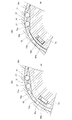
次に、この第4実施形態の逆入力遮断機構3は、図14乃至図16に示すように、出力部を構成するカム部材73の外周に第2実施形態と同様の複数のカム面73aを設けるとともに、カム部材73の入力側面の外周部に第2キャリア46の凸部46bが周方向隙間をもって挿入される係合穴73bを設けることにより、第2実施形態のフランジ22をなくしている。また、ロック解除片16は、柱部16aと係合凹部16bの配置が第2実施形態と逆になっており、外周部に柱部16aが設けられ、内周部に第2キャリア46の凸部46bがカム部材73の係合穴73bよりも狭い周方向隙間をもって挿入される係合凹部16bが設けられている。
Next, as shown in FIGS. 14 to 16, the reverse input blocking mechanism 3 of the fourth embodiment is provided with a plurality of cam surfaces 73a similar to those of the second embodiment on the outer periphery of the cam member 73 constituting the output portion. The flange 22 of the second embodiment is eliminated by providing the engaging hole 73b into which the convex portion 46b of the second carrier 46 is inserted with a circumferential clearance at the outer peripheral portion of the input side surface of the cam member 73. In addition, the lock release piece 16 has an arrangement of the column portion 16a and the engagement recess portion 16b opposite to that of the second embodiment, the column portion 16a is provided on the outer peripheral portion, and the convexity of the second carrier 46 on the inner peripheral portion. An engagement recess 16 b is provided in which the portion 46 b is inserted with a circumferential clearance narrower than the engagement hole 73 b of the cam member 73.
この逆入力遮断機構3の動作は上述した各実施形態とほぼ同じである。すなわち、被駆動部材から出力軸74およびカム部材73に逆入力トルクが加えられても、回転方向後側のころ17がコイルばね18の弾性力によって楔形空間21の狭小部に押し込まれているので、カム部材73が固定外輪15にロックされ、カム部材73および出力軸74は回転せず、被駆動部材の位置は変わらない。
The operation of the reverse input blocking mechanism 3 is almost the same as that of each of the embodiments described above. That is, even when reverse input torque is applied from the driven member to the output shaft 74 and the cam member 73, the roller 17 on the rear side in the rotational direction is pushed into the narrow portion of the wedge-shaped space 21 by the elastic force of the coil spring 18. The cam member 73 is locked to the fixed outer ring 15, the cam member 73 and the output shaft 74 do not rotate, and the position of the driven member does not change.
一方、駆動モータ11が駆動され、その回転が減速されて第2キャリア46に伝達されると、まず、図17(a)に示すように、第2キャリア46の凸部46bが、ロック解除片16の係合凹部16bに係合してロック解除片16を周方向に押す。これにより、ロック解除片16の柱部16aが回転方向後方側のころ17をコイルばね18の弾力に抗して楔形空間21の広大部へ押しやるので、カム部材73と固定外輪15とのロック状態が解除される。そして、図17(b)に示すように、第2キャリア46がさらに回転して、凸部46bがカム部材73の係合穴73bに係合すると、凸部46bがカム部材73を周方向に押すようになり、第2キャリア46の回転がカム部材73および出力軸74に伝達される。
On the other hand, when the drive motor 11 is driven and its rotation is decelerated and transmitted to the second carrier 46, first, as shown in FIG. The lock release piece 16 is pushed in the circumferential direction by engaging with the 16 engagement recesses 16b. Accordingly, the column portion 16a of the unlocking piece 16 pushes the roller 17 on the rear side in the rotation direction against the elasticity of the coil spring 18 to the wide portion of the wedge-shaped space 21, so that the cam member 73 and the fixed outer ring 15 are locked. Is released. As shown in FIG. 17B, when the second carrier 46 further rotates and the convex portion 46b engages with the engagement hole 73b of the cam member 73, the convex portion 46b causes the cam member 73 to move in the circumferential direction. The rotation of the second carrier 46 is transmitted to the cam member 73 and the output shaft 74.
また、図14に示すように、前記出力軸74は、軸受ハウジング77の内周に設けた軸受78で回転自在に支持されており、その出力軸74と軸受ハウジング77との間に出力軸74の回転数を検知する回転検知機構79を設けている。
As shown in FIG. 14, the output shaft 74 is rotatably supported by a bearing 78 provided on the inner periphery of the bearing housing 77, and the output shaft 74 is interposed between the output shaft 74 and the bearing housing 77. A rotation detection mechanism 79 is provided for detecting the number of rotations.
前記回転検知機構79は、出力軸74の外周部の軸方向中央の段差面に取り付けられるエンコーダ80と、軸受ハウジング77と逆入力遮断機構3の固定外輪15とに挟まれるように配されるベース部材81と、ベース部材81にエンコーダ80と軸方向で対向するように取り付けられるセンサ82と、ベース部材81に取り付けられセンサ82を作動させる電子基板83とからなる。
The rotation detection mechanism 79 is a base disposed so as to be sandwiched between an encoder 80 attached to a step surface at the axial center of the outer peripheral portion of the output shaft 74, the bearing housing 77, and the fixed outer ring 15 of the reverse input blocking mechanism 3. A member 81, a sensor 82 attached to the base member 81 so as to face the encoder 80 in the axial direction, and an electronic board 83 attached to the base member 81 and operating the sensor 82.
そして、この回転検知機構79で出力軸74の回転数を検知して、目標回転数との差に応じて駆動モータ11の駆動回転数を修正することにより、出力軸74の回転数を目標回転数に近づけるようにしている。これにより、駆動モータ11と出力軸74との間に介在する第1、第2遊星歯車機構31、41や逆入力遮断機構3等において回転伝達のロスがあっても、出力軸74をほぼ目標回転数で回転させることができる。
Then, the rotation detection mechanism 79 detects the rotation speed of the output shaft 74 and corrects the drive rotation speed of the drive motor 11 in accordance with the difference from the target rotation speed, thereby changing the rotation speed of the output shaft 74 to the target rotation speed. I try to get closer to the number. As a result, even if there is a loss of rotation transmission in the first and second planetary gear mechanisms 31, 41, the reverse input blocking mechanism 3 and the like interposed between the drive motor 11 and the output shaft 74, the output shaft 74 is substantially targeted. It can be rotated at the number of rotations.
また、前記ハウジング71、軸受ハウジング77および回転検知機構79のベース部材81は、互いの軸方向対向面およびハウジング71の分割面に互いに嵌まり合う位置決め用の段差が同心に設けられており、それぞれの段差が嵌合した状態で、各部材の外周側の対応する位置を貫通する複数のボルト孔71d、77a、81aを位置合わせして、各ボルト孔71d、77a、81aに通されるボルトとナット(いずれも図示省略)で一体化されるようになっている。ここで、各部材の段差はなくすこともできるが、この実施形態のように段差を設けた方がボルト孔71d、77a、81aの位置合わせが容易になり、減速機全体の組み立てが効率よく行うことができるので好ましい。
In addition, the housing 71, the bearing housing 77, and the base member 81 of the rotation detection mechanism 79 are provided with concentric positioning steps that fit into the axially opposed surfaces and the dividing surface of the housing 71, respectively. The bolts 71d, 77a, 81a passing through the corresponding positions on the outer peripheral side of each member in a state in which the steps are fitted, and the bolts passed through the bolt holes 71d, 77a, 81a They are integrated with nuts (both not shown). Here, the step of each member can be eliminated. However, if the step is provided as in this embodiment, alignment of the bolt holes 71d, 77a, 81a is facilitated, and the entire reduction gear is efficiently assembled. This is preferable.
そして、軸受ハウジング77およびベース部材81の貫通孔77a、81aの径方向外側には、対応する位置にねじ孔77b、81bがあけられ、これらのねじ孔77b、81bを利用して装置内で固定されるようになっている。
Then, screw holes 77b and 81b are formed at corresponding positions on the outer sides in the radial direction of the through holes 77a and 81a of the bearing housing 77 and the base member 81, and are fixed in the apparatus using these screw holes 77b and 81b. It has come to be.
この第4実施形態の減速機は、上述したように、駆動モータ11、減速機構23、ブレーキとしての逆入力遮断機構3および回転検知機構79がユニット化されているので、特にロボットの関節駆動部に組み込むのに適したものとなっている。
In the speed reducer of the fourth embodiment, as described above, the drive motor 11, the speed reduction mechanism 23, the reverse input blocking mechanism 3 as a brake, and the rotation detection mechanism 79 are unitized. It is suitable for incorporation into.
図18および図19は第5の実施形態を示す。この実施形態は、第1乃至第4の実施形態の遊星歯車機構を用いた減速機構2、23、50に代わる減速機構84として、楕円と真円の差動を利用した波動歯車装置を採用したものである。また、減速機全体の軸方向中央部には、ハウジング1に代わる環状の取付部材91を配している。取付部材91は、その外周部に複数のねじ孔91aがあけられ、これらのねじ孔91aを利用して装置内で固定されるようになっている。
18 and 19 show the fifth embodiment. In this embodiment, a wave gear device using a difference between an ellipse and a perfect circle is employed as a speed reduction mechanism 84 that replaces the speed reduction mechanisms 2, 23, and 50 using the planetary gear mechanisms of the first to fourth embodiments. Is. In addition, an annular mounting member 91 that replaces the housing 1 is disposed in the central portion in the axial direction of the entire speed reducer. The attachment member 91 has a plurality of screw holes 91a formed in the outer peripheral portion thereof, and is fixed in the apparatus using these screw holes 91a.
前記減速機構(波動歯車装置)84は、中空の駆動モータ11の主軸12と回転伝達可能に連結されるウェイブジェネレータ85と、ウェイブジェネレータ85の径方向外側に配されるサーキュラースプライン86と、ウェイブジェネレータ85とサーキュラースプライン86との間に大径部が挟まれるフレックススプライン87とを備えている。サーキュラースプライン86は、軸方向で取付部材91と隣接するように配され、その両者を軸方向で挟む駆動モータ11のフランジ部11aと逆入力遮断機構3の固定外輪15とのボルト結合によって、取付部材91、駆動モータ11および固定外輪15と一体化されている。
The speed reduction mechanism (wave gear device) 84 includes a wave generator 85 coupled to the main shaft 12 of the hollow drive motor 11 so as to be able to transmit rotation, a circular spline 86 disposed radially outward of the wave generator 85, and a wave generator. A flex spline 87 having a large diameter portion sandwiched between 85 and the circular spline 86 is provided. The circular spline 86 is arranged so as to be adjacent to the attachment member 91 in the axial direction, and is attached by bolt connection between the flange portion 11a of the drive motor 11 that sandwiches both of them in the axial direction and the fixed outer ring 15 of the reverse input blocking mechanism 3. The member 91, the drive motor 11, and the fixed outer ring 15 are integrated.
前記ウェイブジェネレータ85は、径方向断面が楕円形のカム85aの外周にボールベアリング85bの内輪を嵌合固定したもので、中空の回り止め部材88を介して駆動モータ11の主軸12に連結され、減速機構84の入力側部材となっている。サーキュラースプライン86は、その内周に歯が設けられた円環状の部品であり、取付部材91を介して装置内で固定されている。また、フレックススプライン87は、金属弾性体で形成された薄肉カップ状の部品で、大径部の外周にサーキュラースプライン86内周の歯と噛み合う歯が設けられており、小径部(一端部)で逆入力遮断機構3の入力部となる入力ピン89と回転伝達可能に連結され、減速機構84の出力側部材となっている。
The wave generator 85 is obtained by fitting and fixing an inner ring of a ball bearing 85b on the outer periphery of a cam 85a having an elliptical cross section in the radial direction. The wave generator 85 is connected to the main shaft 12 of the drive motor 11 via a hollow detent member 88. This is an input side member of the speed reduction mechanism 84. The circular spline 86 is an annular part having teeth provided on the inner periphery thereof, and is fixed in the apparatus via an attachment member 91. The flex spline 87 is a thin cup-shaped part formed of a metal elastic body, and teeth that mesh with teeth on the inner periphery of the circular spline 86 are provided on the outer periphery of the large diameter portion. The reverse input blocking mechanism 3 is connected to an input pin 89 serving as an input portion so as to be able to transmit rotation, and serves as an output side member of the speed reduction mechanism 84.
そして、駆動モータ11の駆動によりウェイブジェネレータ85が回転すると、ウェイブジェネレータ85のボールベアリング85bの外輪に大径部内周を押圧されたフレックススプライン87が、弾性変形してサーキュラースプライン86との噛合位置を変えていくことによりサーキュラースプライン86との歯数の差分だけ回転し、その回転が逆入力遮断機構3の入力ピン89に伝達されるようになっている。
When the wave generator 85 is rotated by driving the drive motor 11, the flex spline 87 whose large diameter inner periphery is pressed by the outer ring of the ball bearing 85 b of the wave generator 85 is elastically deformed to change the meshing position with the circular spline 86. By changing the rotation, the rotation is made by the difference in the number of teeth from the circular spline 86, and the rotation is transmitted to the input pin 89 of the reverse input blocking mechanism 3.
ここで、駆動モータ11のフランジ部11aの内周には、フレックススプライン87の大径部の端面(他端面)と摺接する位置に円筒状のガイド部材90が固定されており、このガイド部材90でフレックススプライン87(およびその一端面に当接する逆入力遮断機構3のロック解除片16)の他端側への軸方向移動を規制することにより、回転伝達動作の安定性を確保している。なお、フレックススプライン87およびロック解除片16の一端側への軸方向移動は、ロック解除片16が逆入力遮断機構3のカム部材73に当接することにより規制されている。
Here, on the inner periphery of the flange portion 11 a of the drive motor 11, a cylindrical guide member 90 is fixed at a position in sliding contact with the end surface (other end surface) of the large-diameter portion of the flex spline 87. Thus, by restricting the axial movement of the flex spline 87 (and the unlocking piece 16 of the reverse input blocking mechanism 3 in contact with one end face thereof) to the other end side, the stability of the rotation transmission operation is ensured. The axial movement of the flex spline 87 and the lock release piece 16 toward one end is restricted by the lock release piece 16 coming into contact with the cam member 73 of the reverse input blocking mechanism 3.
この第5実施形態では、上述したように、減速機構84として波動歯車装置を採用したので、高い減速率が得られるし、第2乃至第4実施形態のように2つの遊星歯車機構を軸方向に並べて組み込んだ減速機構を採用する場合に比べて、減速機全体の構造の簡素化および軸方向寸法のコンパクト化を図ることができる。
In the fifth embodiment, as described above, since the wave gear device is employed as the speed reduction mechanism 84, a high speed reduction rate can be obtained, and the two planetary gear mechanisms can be moved in the axial direction as in the second to fourth embodiments. Compared with a case where a speed reduction mechanism arranged side by side is adopted, the structure of the entire speed reducer can be simplified and the axial dimension can be made compact.
一方、この第5実施形態の逆入力遮断機構3は、第4実施形態のものと基本的な構成および動作は同じであるので、主として第4実施形態との相違点について説明する。
On the other hand, since the reverse input blocking mechanism 3 of the fifth embodiment has the same basic configuration and operation as that of the fourth embodiment, differences from the fourth embodiment will be mainly described.
まず、逆入力遮断機構3の出力部となるカム部材73には、第4実施形態の係合穴73bの代わりに、入力部となる入力ピン89の先端側外周に嵌合固定されたスリーブ92が周方向隙間をもって挿入される係合穴73cが設けられている。また、ロック解除片16には、第4実施形態の係合凹部16bの代わりに、入力ピン89の中央部が周方向隙間をもって挿入される係合穴16cが設けられている。そのロック解除片16の係合穴16cの入力ピン89中央部との周方向隙間は、カム部材73の係合穴73cのスリーブ92との周方向隙間よりも狭く形成されている。
First, a sleeve 92 fitted and fixed to the outer periphery on the distal end side of an input pin 89 serving as an input portion is attached to a cam member 73 serving as an output portion of the reverse input blocking mechanism 3 instead of the engagement hole 73b of the fourth embodiment. Is provided with an engagement hole 73c into which a gap is inserted with a circumferential clearance. Further, the lock release piece 16 is provided with an engagement hole 16c into which the central portion of the input pin 89 is inserted with a circumferential clearance instead of the engagement recess 16b of the fourth embodiment. The circumferential clearance between the engagement hole 16 c of the lock release piece 16 and the central portion of the input pin 89 is narrower than the circumferential clearance between the engagement hole 73 c of the cam member 73 and the sleeve 92.
これにより、駆動モータ11の回転が減速機構84で減速されて入力ピン89に伝達されると、第4実施形態と同様に、入力ピン89の中央部がロック解除片16の係合穴16cに係合してロック解除片16を周方向に押し、ロック解除片16がロック状態を解除した後に、入力ピン89先端側のスリーブ92がカム部材73の係合穴73cに係合してカム部材73を周方向に押し、入力ピン89の回転がカム部材73に伝達されるようになっている。
As a result, when the rotation of the drive motor 11 is decelerated by the speed reduction mechanism 84 and transmitted to the input pin 89, the central portion of the input pin 89 is inserted into the engagement hole 16c of the lock release piece 16 as in the fourth embodiment. After engaging and pushing the unlocking piece 16 in the circumferential direction, the unlocking piece 16 releases the locked state, and then the sleeve 92 on the distal end side of the input pin 89 engages with the engaging hole 73c of the cam member 73 and the cam member The rotation of the input pin 89 is transmitted to the cam member 73 by pushing 73 in the circumferential direction.
また、逆入力遮断機構3のカム部材73と被駆動部材に接続される接続部材93との間にはクロスローラ軸受94が設けられている。クロスローラ軸受94は、内輪95と外輪96の間に複数のローラ97を周方向で隣り合うものどうしが互いに直交するように配したもので、その内輪95がカム部材73および接続部材93と一体回転するようにボルト結合され、外輪96が逆入力遮断機構3の固定外輪15にボルト結合されている。これにより、減速機全体のスラスト力に対する剛性が大きくなり、回転伝達動作の安定性が高くなっている。
Further, a cross roller bearing 94 is provided between the cam member 73 of the reverse input blocking mechanism 3 and the connecting member 93 connected to the driven member. The cross roller bearing 94 includes a plurality of rollers 97 arranged between an inner ring 95 and an outer ring 96 so that adjacent ones in the circumferential direction are orthogonal to each other, and the inner ring 95 is integrated with the cam member 73 and the connecting member 93. The outer ring 96 is bolted to the fixed outer ring 15 of the reverse input blocking mechanism 3. Thereby, the rigidity with respect to the thrust force of the entire reduction gear is increased, and the stability of the rotation transmission operation is increased.
また、クロスローラ軸受94の外輪96と接続部材93との間には、第4実施形態と同様の回転検知機構79が設けられている。回転検知機構79は、接続部材93の外周面に嵌合固定された断面略U字状のリング部材98の内側面に取り付けられるエンコーダ80と、クロスローラ軸受94の外輪96の外側端面に取り付けられる電子基板83と、電子基板83にエンコーダ80と軸方向で対向するように取り付けられるセンサ82とからなる。
Further, a rotation detection mechanism 79 similar to that in the fourth embodiment is provided between the outer ring 96 of the cross roller bearing 94 and the connection member 93. The rotation detection mechanism 79 is attached to the outer end surface of the outer ring 96 of the outer ring 96 of the cross roller bearing 94 and the encoder 80 attached to the inner side surface of the ring member 98 having a substantially U-shaped cross section fitted and fixed to the outer peripheral surface of the connection member 93. The electronic board 83 includes a sensor 82 attached to the electronic board 83 so as to face the encoder 80 in the axial direction.
そして、この回転検知機構79で逆入力遮断機構3のカム部材73と一体回転する接続部材93およびリング部材98の回転数を検知して、目標回転数との差に応じて駆動モータ11の駆動回転数を修正することにより、回転速度精度の向上が図れるようになっている。
Then, the rotation detection mechanism 79 detects the rotation speed of the connection member 93 and the ring member 98 that rotate integrally with the cam member 73 of the reverse input blocking mechanism 3, and drives the drive motor 11 according to the difference from the target rotation speed. The rotational speed accuracy can be improved by correcting the rotational speed.
図20および図21は、第5実施形態の減速機構84のフレックススプライン87および逆入力遮断機構3のロック解除片16の他端側への軸方向移動を規制する手段の変形例を示す。
20 and 21 show a modification of the means for restricting the axial movement of the flex spline 87 of the speed reduction mechanism 84 and the unlocking piece 16 of the reverse input blocking mechanism 3 to the other end side of the fifth embodiment.
この変形例では、フレックススプライン87の小径部とロック解除片16とを貫通する入力ピン89の先端側にスリーブ92に代わる大径部89aを設け、その大径部89aとフレックススプライン87の小径部から突出する部分にねじ結合するナット99とで、フレックススプライン87の小径部とロック解除片16を挟んで締め付けている。そして、カム部材73の係合穴73cの周縁に、入力ピン89の大径部89aの途中に設けた段差面とロック解除片16との間に挿入される環状のガイド部73dを設けている。これにより、カム部材73のガイド部73dが入力ピン89の大径部89aと係合して、フレックススプライン87およびロック解除片16の他端側への軸方向移動が規制される。
In this modification, a large-diameter portion 89a is provided in place of the sleeve 92 on the distal end side of the input pin 89 that passes through the small-diameter portion of the flex spline 87 and the unlocking piece 16, and the large-diameter portion 89a and the small-diameter portion of the flex spline 87 are provided. The nut 99 that is screw-coupled to the portion protruding from the pin is clamped by sandwiching the small diameter portion of the flex spline 87 and the lock release piece 16. An annular guide portion 73 d that is inserted between the step surface provided in the middle of the large-diameter portion 89 a of the input pin 89 and the lock release piece 16 is provided on the periphery of the engagement hole 73 c of the cam member 73. . As a result, the guide portion 73d of the cam member 73 engages with the large-diameter portion 89a of the input pin 89, and the axial movement of the flex spline 87 and the lock release piece 16 toward the other end side is restricted.
したがって、図18および図19で示した例に比べると、フレックススプライン87の大径部の端面と摺接するガイド部材90を省略して部品点数を減らせるし、逆入力遮断機構3のロック解除後は入力ピン89がカム部材73を押してカム部材73とほぼ一体に回転するようになるので、摺動箇所が少なくなり、減速機全体の低トルク化が可能となる。
Therefore, compared with the example shown in FIGS. 18 and 19, the guide member 90 slidably contacting the end surface of the large-diameter portion of the flex spline 87 can be omitted to reduce the number of parts, and after the reverse input blocking mechanism 3 is unlocked Since the input pin 89 pushes the cam member 73 and rotates almost integrally with the cam member 73, the number of sliding parts is reduced, and the torque of the entire speed reducer can be reduced.
1 ハウジング
1a 前半部
1b 後半部
1e、1f 取付片
1g、1h 切れ込み
2、23、50 減速機構
3 逆入力遮断機構
4、32、42、52、62 入力軸
5、33、43、53、63 太陽歯車
6、34、44、54、64 内歯車
7、35、45、55、65 遊星歯車
8、36、46、56、66 キャリア
8a、36a、46a、56a、66a 支軸
8b、46b、66b 凸部
8d 回転伝達軸
10 入力歯車
11 駆動モータ
12 主軸
13 伝達歯車
14 出力軸
14d 第3の係合穴
15 固定外輪
16 ロック解除片
16a 柱部
16b 第1の係合穴
17 ころ
18 コイルばね
20 出力歯車
21 楔形空間
22 フランジ
22a 第2の係合穴
24、25 入力歯車
27 駆動軸
28、29 伝達歯車
30、67 手動操作部
31、41、51、61 遊星歯車機構
71 ハウジング
71a 前半部
71b 後半部
71c 内筒部
71d ボルト孔
72 入力軸
73 カム部材
73d ガイド部
74 出力軸
75 入力歯車
76 伝達歯車
79 回転検知機構
84 減速機構(波動歯車装置)
85 ウェイブジェネレータ
86 サーキュラースプライン
87 フレックススプライン
89 入力ピン
90 ガイド部材
91 取付部材
92 スリーブ
93 接続部材
94 クロスローラ軸受 DESCRIPTION OFSYMBOLS 1 Housing 1a Front half part 1b Rear half part 1e, 1f Attachment piece 1g, 1h Notch 2, 23, 50 Reduction mechanism 3 Reverse input interruption | blocking mechanism 4, 32, 42, 52, 62 Input shaft 5, 33, 43, 53, 63 Sun Gears 6, 34, 44, 54, 64 Internal gears 7, 35, 45, 55, 65 Planetary gears 8, 36, 46, 56, 66 Carriers 8a, 36a, 46a, 56a, 66a Support shafts 8b, 46b, 66b Convex Portion 8d Rotation transmission shaft 10 Input gear 11 Drive motor 12 Main shaft 13 Transmission gear 14 Output shaft 14d Third engagement hole 15 Fixed outer ring 16 Unlocking piece 16a Column 16b First engagement hole 17 Roller 18 Coil spring 20 Output Gear 21 Wedge-shaped space 22 Flange 22a Second engagement hole 24, 25 Input gear 27 Drive shaft 28, 29 Transmission gear 30, 67 Manual operation unit 31, 41, 51, 61 Star gear mechanism 71 housing 71a first half 71b latter part 71c in the tubular portion 71d bolt hole 72 input shaft 73 the cam member 73d guide section 74 output shaft 75 input gear 76 transmission gear 79 rotation detection mechanism 84 reduction mechanism (wave gear device)
85Wave generator 86 Circular spline 87 Flex spline 89 Input pin 90 Guide member 91 Mounting member 92 Sleeve 93 Connection member 94 Cross roller bearing
1a 前半部
1b 後半部
1e、1f 取付片
1g、1h 切れ込み
2、23、50 減速機構
3 逆入力遮断機構
4、32、42、52、62 入力軸
5、33、43、53、63 太陽歯車
6、34、44、54、64 内歯車
7、35、45、55、65 遊星歯車
8、36、46、56、66 キャリア
8a、36a、46a、56a、66a 支軸
8b、46b、66b 凸部
8d 回転伝達軸
10 入力歯車
11 駆動モータ
12 主軸
13 伝達歯車
14 出力軸
14d 第3の係合穴
15 固定外輪
16 ロック解除片
16a 柱部
16b 第1の係合穴
17 ころ
18 コイルばね
20 出力歯車
21 楔形空間
22 フランジ
22a 第2の係合穴
24、25 入力歯車
27 駆動軸
28、29 伝達歯車
30、67 手動操作部
31、41、51、61 遊星歯車機構
71 ハウジング
71a 前半部
71b 後半部
71c 内筒部
71d ボルト孔
72 入力軸
73 カム部材
73d ガイド部
74 出力軸
75 入力歯車
76 伝達歯車
79 回転検知機構
84 減速機構(波動歯車装置)
85 ウェイブジェネレータ
86 サーキュラースプライン
87 フレックススプライン
89 入力ピン
90 ガイド部材
91 取付部材
92 スリーブ
93 接続部材
94 クロスローラ軸受 DESCRIPTION OF
85
Claims (14)
- 駆動モータの回転を減速して被駆動部材の側へ出力する減速機構に、前記駆動モータ停止時に被駆動部材の位置を保持するブレーキとして、前記減速機構の出力側部材と回転伝達可能に連結される入力部と、前記被駆動部材と回転伝達可能に連結される出力部とを備え、前記入力部に入力トルクが加えられたときは入力部の回転を出力部に伝達し、前記出力部に逆入力トルクが加えられたときにはロックして出力部を停止させる逆入力遮断機構を付設したブレーキ付減速機。 A deceleration mechanism that decelerates the rotation of the drive motor and outputs it to the driven member side is connected to the output-side member of the deceleration mechanism as a brake that holds the position of the driven member when the drive motor is stopped. And an output unit connected to the driven member so as to be able to transmit rotation. When input torque is applied to the input unit, the rotation of the input unit is transmitted to the output unit, and the output unit is connected to the output unit. A speed reducer with brake, which is equipped with a reverse input shut-off mechanism that locks and stops the output section when reverse input torque is applied.
- 前記逆入力遮断機構が、前記出力部を固定部材にロックするロック手段と、前記入力トルクが加えられたときに前記入力部の回転により前記出力部と固定部材とのロック状態を解除するロック解除手段と、前記ロック状態が解除されたときに前記入力部の回転を僅かな角度遅れをもって前記出力部に伝達するトルク伝達手段とを備えた逆入力遮断クラッチであることを特徴とする請求項1に記載のブレーキ付減速機。 The reverse input blocking mechanism is a lock unit that locks the output unit to a fixed member, and unlocking that releases the locked state between the output unit and the fixed member by rotation of the input unit when the input torque is applied. 2. A reverse input cut-off clutch comprising: means and torque transmitting means for transmitting rotation of the input unit to the output unit with a slight angular delay when the locked state is released. Reducer with brake as described in 1.
- 前記ロック手段が、前記出力部の径方向外側に前記固定部材として内周に円筒面を有する固定外輪を配し、前記出力部の外周にカム面を設けて、前記出力部と固定外輪との間に周方向両側で次第に狭小となる楔形空間を複数形成し、これらの各楔形空間に一対のころと各ころを楔形空間の狭小部に押し込むばねを組み込んだものであり、
前記ロック解除手段が、前記出力部の径方向外側に円環状のロック解除片を配し、このロック解除片に前記各楔形空間の周方向両側に挿入される複数の柱部と第1の係合穴を設け、前記入力部に前記ロック解除片の第1の係合穴に周方向隙間をもって挿入される凸部を設け、前記入力部が回転したときに、その凸部が前記第1の係合穴に係合して前記ロック解除片を周方向に押すことにより、前記ロック解除片の柱部が回転方向後方側のころをばねの弾力に抗して楔形空間の広大部へ押しやるようにしたものであり、
前記トルク伝達手段が、前記出力部に前記入力部の凸部が前記第1の係合穴よりも広い周方向隙間をもって挿入される第2の係合穴を設け、前記ロック状態が解除された後に、前記入力部の凸部が前記第2の係合穴に係合して前記出力部を周方向に押すようにしたものであることを特徴とする請求項2に記載のブレーキ付減速機。 The locking means includes a fixed outer ring having a cylindrical surface on the inner periphery as the fixing member on the radially outer side of the output portion, and a cam surface is provided on the outer periphery of the output portion. A plurality of wedge-shaped spaces that gradually narrow on both sides in the circumferential direction are formed, and a pair of rollers and a spring that pushes each roller into the narrow portion of the wedge-shaped space are incorporated in each wedge-shaped space,
The lock release means includes an annular lock release piece radially outside the output portion, and a plurality of column portions inserted into the lock release piece on both sides in the circumferential direction of each wedge-shaped space and the first engagement. A fitting hole is provided, and a convex portion inserted into the first engagement hole of the unlocking piece with a circumferential clearance is provided in the input portion. When the input portion rotates, the convex portion is By engaging the engagement hole and pushing the unlocking piece in the circumferential direction, the column part of the unlocking piece pushes the roller on the rear side in the rotation direction against the elasticity of the spring to the wide part of the wedge-shaped space. And
The torque transmitting means is provided with a second engagement hole into which the convex portion of the input portion is inserted with a wider circumferential clearance than the first engagement hole, and the locked state is released. 3. A brake with a brake according to claim 2, wherein a convex portion of the input portion is engaged with the second engagement hole to push the output portion in the circumferential direction. . - 前記減速機構の入力側部材に手動操作部を連結したことを特徴とする請求項1乃至3のいずれかに記載のブレーキ付減速機。 A brake-equipped reducer according to any one of claims 1 to 3, wherein a manual operation unit is connected to an input side member of the reduction mechanism.
- 前記手動操作部を前記減速機構の入力側部材に対して脱着可能としたことを特徴とする請求項4に記載のブレーキ付減速機。 The brake-equipped reducer according to claim 4, wherein the manual operation unit is detachable from an input side member of the reduction mechanism.
- 前記減速機構が、軸方向に並べて組み込んだ2つの遊星歯車機構の差動運動を利用するものであり、その減速機構の入力軸の外周に入力歯車を嵌合固定し、前記駆動モータの主軸の外周に、前記入力歯車よりも少ない歯数で入力歯車と噛み合う伝達歯車を嵌合固定したことを特徴とする請求項1乃至5のいずれかに記載のブレーキ付減速機。 The speed reduction mechanism utilizes the differential motion of two planetary gear mechanisms incorporated side by side in the axial direction. The input gear is fitted and fixed to the outer periphery of the input shaft of the speed reduction mechanism, and the main shaft of the drive motor The reduction gear with a brake according to any one of claims 1 to 5, wherein a transmission gear that meshes with the input gear with a smaller number of teeth than the input gear is fitted and fixed to the outer periphery.
- 前記減速機構の入力軸の軸心の周りに前記駆動モータを複数配置し、前記各駆動モータの主軸の外周に前記伝達歯車を嵌合固定したことを特徴とする請求項6に記載のブレーキ付減速機。 The brake according to claim 6, wherein a plurality of the drive motors are arranged around the axis of the input shaft of the speed reduction mechanism, and the transmission gear is fitted and fixed to the outer periphery of the main shaft of each drive motor. Decelerator.
- 前記減速機構が、前記駆動モータと回転伝達可能に連結される入力側部材となるウェイブジェネレータと、前記ウェイブジェネレータの径方向外側で固定されるサーキュラースプラインと、前記ウェイブジェネレータとサーキュラースプラインとの間に配され、一端部で前記逆入力遮断機構の入力部と回転伝達可能に連結される出力側部材となるフレックススプラインとからなる波動歯車装置であることを特徴とする請求項1乃至5のいずれかに記載のブレーキ付減速機。 The speed reduction mechanism is a wave generator serving as an input side member connected to the drive motor so as to be able to transmit rotation, a circular spline fixed radially outside the wave generator, and the wave generator and the circular spline. 6. A wave gear device comprising a flex spline serving as an output side member disposed at one end and connected to an input portion of the reverse input blocking mechanism so as to transmit rotation. Reducer with brake as described in 1.
- 前記フレックススプラインの他端面と摺接する位置で固定され、フレックススプラインの他端側への軸方向移動を規制するガイド部材を設けたことを特徴とする請求項8に記載のブレーキ付減速機。 The speed reducer with a brake according to claim 8, further comprising a guide member that is fixed at a position in sliding contact with the other end surface of the flex spline, and that regulates axial movement toward the other end of the flex spline.
- 前記フレックススプラインを前記逆入力遮断機構の入力部と軸方向に結合し、前記逆入力遮断機構の入力部と係合してフレックススプラインの他端側への軸方向移動を規制するガイド部を逆入力遮断機構の出力部に設けたことを特徴とする請求項8に記載のブレーキ付減速機。 The flex spline is coupled to the input portion of the reverse input blocking mechanism in the axial direction, and the guide portion that engages with the input portion of the reverse input blocking mechanism to restrict the axial movement of the flex spline to the other end is reversed. The speed reducer with brake according to claim 8, wherein the speed reducer is provided at an output portion of the input blocking mechanism.
- 前記逆入力遮断機構の出力部と被駆動部材との間に、内輪が前記逆入力遮断機構の出力部および被駆動部材と回転伝達可能に連結され、外輪が固定されたクロスローラ軸受を設けたことを特徴とする請求項1乃至10のいずれかに記載のブレーキ付減速機。 Provided between the output portion of the reverse input blocking mechanism and the driven member is a cross roller bearing in which an inner ring is connected to the output portion of the reverse input blocking mechanism and the driven member so as to be able to transmit rotation, and the outer ring is fixed. The speed reducer with a brake according to any one of claims 1 to 10.
- 前記逆入力遮断機構の出力部の回転数を検知し、検知された回転数と予め設定された目標回転数との差に応じて前記駆動モータの駆動回転数を修正するようにしたことを特徴とする請求項1乃至11のいずれかに記載のブレーキ付減速機。 The rotational speed of the output part of the reverse input shut-off mechanism is detected, and the drive rotational speed of the drive motor is corrected according to the difference between the detected rotational speed and a preset target rotational speed. The speed reducer with a brake according to any one of claims 1 to 11.
- 前記駆動モータ、減速機構および逆入力遮断機構を一つのハウジングの内部に設けてユニット化するとともに、前記ハウジングは、軸方向に複数に分割されており、その分割面に互いに嵌まり合う位置決め用の段差が同心に設けられ、前記分割面の段差が嵌合した状態でハウジング全体を貫通するボルト孔を位置合わせして、前記ボルト孔に通したボルトとナットで一体化されるものとしたことを特徴とする請求項1乃至12のいずれかに記載のブレーキ付減速機。 The drive motor, the speed reduction mechanism, and the reverse input blocking mechanism are provided in a single housing to form a unit, and the housing is divided into a plurality of parts in the axial direction, and the positioning motors fit to each other on the divided surfaces. Steps are provided concentrically, with the bolt holes penetrating the entire housing in a state where the steps of the dividing surfaces are fitted, and integrated with bolts and nuts passed through the bolt holes. The speed reducer with a brake according to any one of claims 1 to 12.
- ロボットの関節駆動部に組み込まれることを特徴とする請求項1乃至13のいずれかに記載のブレーキ付減速機。 14. The brake with a brake according to any one of claims 1 to 13, which is incorporated in a joint drive unit of a robot.
Priority Applications (3)
| Application Number | Priority Date | Filing Date | Title |
|---|---|---|---|
| CN201580006342.7A CN105940246A (en) | 2014-01-28 | 2015-01-23 | Reduction gear with brake |
| US15/114,553 US20160341267A1 (en) | 2014-01-28 | 2015-01-23 | Speed reducer with a brake |
| EP15743664.3A EP3101314A4 (en) | 2014-01-28 | 2015-01-23 | Reduction gear with brake |
Applications Claiming Priority (6)
| Application Number | Priority Date | Filing Date | Title |
|---|---|---|---|
| JP2014-013311 | 2014-01-28 | ||
| JP2014013311 | 2014-01-28 | ||
| JP2014-078373 | 2014-04-07 | ||
| JP2014078373 | 2014-04-07 | ||
| JP2014209700A JP2015206455A (en) | 2014-01-28 | 2014-10-14 | Reduction gear with brake |
| JP2014-209700 | 2014-10-14 |
Publications (1)
| Publication Number | Publication Date |
|---|---|
| WO2015115324A1 true WO2015115324A1 (en) | 2015-08-06 |
Family
ID=53756898
Family Applications (1)
| Application Number | Title | Priority Date | Filing Date |
|---|---|---|---|
| PCT/JP2015/051823 WO2015115324A1 (en) | 2014-01-28 | 2015-01-23 | Reduction gear with brake |
Country Status (5)
| Country | Link |
|---|---|
| US (1) | US20160341267A1 (en) |
| EP (1) | EP3101314A4 (en) |
| JP (1) | JP2015206455A (en) |
| CN (1) | CN105940246A (en) |
| WO (1) | WO2015115324A1 (en) |
Cited By (6)
| Publication number | Priority date | Publication date | Assignee | Title |
|---|---|---|---|---|
| WO2017186844A1 (en) * | 2016-04-27 | 2017-11-02 | Ovalo Gmbh | Motorized articulation for a programmable motion automaton |
| WO2017186845A1 (en) * | 2016-04-27 | 2017-11-02 | Ovalo Gmbh | Motorized joint for a programmable moving machine |
| WO2017186843A1 (en) * | 2016-04-27 | 2017-11-02 | Ovalo Gmbh | Motorized joint for a programmable automatic moving unit |
| CN110033692A (en) * | 2019-04-28 | 2019-07-19 | 重庆理工大学 | A kind of planetary gear mechanism movement instructional device |
| US11111984B2 (en) | 2016-08-05 | 2021-09-07 | Fanuc Corporation | Rotary axis module and articulated robot |
| CN113618774A (en) * | 2021-07-19 | 2021-11-09 | 安徽工程大学 | Variable-stiffness transmission joint based on cam mechanism and switching control method |
Families Citing this family (18)
| Publication number | Priority date | Publication date | Assignee | Title |
|---|---|---|---|---|
| CN108496026B (en) * | 2016-02-02 | 2020-12-22 | 谐波传动系统有限公司 | Wave gear device and actuator |
| CN109891125B (en) * | 2016-10-19 | 2021-11-26 | 三菱电机株式会社 | Speed reduction device and robot |
| US11564452B2 (en) * | 2016-12-09 | 2023-01-31 | Adamant Namiki Precision Jewel Co., Ltd. | Winding device |
| HUE043223T2 (en) * | 2017-01-24 | 2019-08-28 | Lakeview Innovation Ltd | Compact multi-stage transmission comprising a planetary gear and a subsequent shaft drive |
| FR3065266B1 (en) * | 2017-04-14 | 2020-07-31 | Bernard Controls | EPICYCLOIDAL TRAIN ADVANTAGEALLY FOR A SERVOMOTOR SYSTEM AND SERVOMOTOR SYSTEM USING THIS EPICYCLOIDAL TRAIN |
| JP2019163698A (en) * | 2018-03-19 | 2019-09-26 | 日立オートモティブシステムズ株式会社 | Actuator of variable compression ratio mechanism of internal combustion engine and wave gear reducer |
| US11027438B2 (en) * | 2018-07-13 | 2021-06-08 | A-Dec, Inc. | Positive positioning device and system |
| CN109129552B (en) * | 2018-09-19 | 2023-10-03 | 广东工业大学 | Robot coupling assembling based on wedge |
| TW202033338A (en) * | 2019-01-30 | 2020-09-16 | 日商京洛股份有限公司 | Molding device and system for producing molded article |
| CN109895081A (en) * | 2019-04-30 | 2019-06-18 | 深圳市爱因派科技有限公司 | The high-precision steering engine and robot of electromechanical integration |
| US11696806B2 (en) * | 2019-07-23 | 2023-07-11 | Verb Surgical Inc. | Strain wave gearing with input to output braking |
| WO2021056173A1 (en) * | 2019-09-24 | 2021-04-01 | Shanghai Flexiv Robotics Technology Co., Ltd. | Brake mechanism, joint actuator, and robot |
| CN112936334B (en) * | 2021-02-10 | 2022-07-12 | 镇江星河机器人有限公司 | Robot joint module motor and accurate control method thereof |
| FR3127268A1 (en) * | 2021-09-17 | 2023-03-24 | Robocath | ARTICULATED ROBOT SUPPORT ARM EXTENDED FLEXIBLE MEDICAL DEVICE HANDLING CATHETER INCLUDING A BRAKE |
| CN113833780B (en) * | 2021-10-21 | 2023-07-25 | 杭州速博雷尔传动机械有限公司 | High-efficient double-brake speed reducer |
| TWI785874B (en) * | 2021-11-02 | 2022-12-01 | 財團法人工業技術研究院 | Transmission module |
| DE202022103346U1 (en) | 2022-06-14 | 2023-09-22 | Dellner Bubenzer Germany Gmbh | Speedometer arrangement for an engine mounting brake, engine mounting brake and drive arrangement |
| CN115553924B (en) * | 2022-12-02 | 2023-03-10 | 北京云力境安科技有限公司 | Flexible instrument conveying device and execution component and driving component thereof |
Citations (11)
| Publication number | Priority date | Publication date | Assignee | Title |
|---|---|---|---|---|
| JPS6023654A (en) | 1983-07-15 | 1985-02-06 | Hitachi Ltd | Speed change gear |
| JPS6372943A (en) * | 1986-09-10 | 1988-04-02 | Fujio Hisashi | Gear reduction power transmission device |
| JPH06285785A (en) | 1993-03-31 | 1994-10-11 | Yaskawa Electric Corp | Arm retracting device and method for industrial robot |
| JPH0783293A (en) * | 1993-09-14 | 1995-03-28 | Secoh Giken Inc | Differential star gear device |
| JP2003056596A (en) * | 2001-08-09 | 2003-02-26 | Ntn Corp | Rotating device with clutch |
| JP2003083416A (en) * | 2001-09-13 | 2003-03-19 | Sumitomo Heavy Ind Ltd | Ball screw lubricating device for molding machine and lubricating method |
| JP2004162730A (en) * | 2002-11-08 | 2004-06-10 | Ntn Corp | Magnetic levitation rotation device |
| JP2007321879A (en) * | 2006-06-01 | 2007-12-13 | Harmonic Drive Syst Ind Co Ltd | Reduction gear unit with rotational position sensor |
| JP2009166168A (en) * | 2008-01-15 | 2009-07-30 | Sumitomo Heavy Ind Ltd | Joint driving device of robot |
| JP2010041747A (en) * | 2008-07-31 | 2010-02-18 | Chiba Inst Of Technology | Motor device |
| JP2013099191A (en) * | 2011-11-04 | 2013-05-20 | Seiko Epson Corp | Electro-mechanical device, actuator using the same, motor, robot and robot hand |
Family Cites Families (9)
| Publication number | Priority date | Publication date | Assignee | Title |
|---|---|---|---|---|
| US2240043A (en) * | 1939-12-28 | 1941-04-29 | Kinser Vernon | Automatic shaft brake device |
| GB2210941B (en) * | 1987-10-09 | 1991-11-13 | Ntn Toyo Bearing Co Ltd | Clutch |
| JP2002213486A (en) * | 2001-01-22 | 2002-07-31 | Ntn Corp | Rotational driving device |
| DE60215854T2 (en) * | 2001-03-08 | 2007-06-28 | Ntn Corp. | Reverse locking clutch |
| JP2003166570A (en) * | 2001-11-29 | 2003-06-13 | Advics:Kk | Electrical parking brake system |
| JP4789000B2 (en) * | 2006-02-16 | 2011-10-05 | Smc株式会社 | Automatic reduction ratio switching device |
| CN100369724C (en) * | 2006-02-28 | 2008-02-20 | 哈尔滨工业大学 | Modularized joint of space manipulator |
| WO2010004880A1 (en) * | 2008-07-09 | 2010-01-14 | Ntn株式会社 | Reduction gear and variable valve timing device using same |
| JP2012122585A (en) * | 2010-12-10 | 2012-06-28 | Ntn Corp | Reverse input blocking clutch |
-
2014
- 2014-10-14 JP JP2014209700A patent/JP2015206455A/en active Pending
-
2015
- 2015-01-23 EP EP15743664.3A patent/EP3101314A4/en not_active Withdrawn
- 2015-01-23 WO PCT/JP2015/051823 patent/WO2015115324A1/en active Application Filing
- 2015-01-23 CN CN201580006342.7A patent/CN105940246A/en active Pending
- 2015-01-23 US US15/114,553 patent/US20160341267A1/en not_active Abandoned
Patent Citations (11)
| Publication number | Priority date | Publication date | Assignee | Title |
|---|---|---|---|---|
| JPS6023654A (en) | 1983-07-15 | 1985-02-06 | Hitachi Ltd | Speed change gear |
| JPS6372943A (en) * | 1986-09-10 | 1988-04-02 | Fujio Hisashi | Gear reduction power transmission device |
| JPH06285785A (en) | 1993-03-31 | 1994-10-11 | Yaskawa Electric Corp | Arm retracting device and method for industrial robot |
| JPH0783293A (en) * | 1993-09-14 | 1995-03-28 | Secoh Giken Inc | Differential star gear device |
| JP2003056596A (en) * | 2001-08-09 | 2003-02-26 | Ntn Corp | Rotating device with clutch |
| JP2003083416A (en) * | 2001-09-13 | 2003-03-19 | Sumitomo Heavy Ind Ltd | Ball screw lubricating device for molding machine and lubricating method |
| JP2004162730A (en) * | 2002-11-08 | 2004-06-10 | Ntn Corp | Magnetic levitation rotation device |
| JP2007321879A (en) * | 2006-06-01 | 2007-12-13 | Harmonic Drive Syst Ind Co Ltd | Reduction gear unit with rotational position sensor |
| JP2009166168A (en) * | 2008-01-15 | 2009-07-30 | Sumitomo Heavy Ind Ltd | Joint driving device of robot |
| JP2010041747A (en) * | 2008-07-31 | 2010-02-18 | Chiba Inst Of Technology | Motor device |
| JP2013099191A (en) * | 2011-11-04 | 2013-05-20 | Seiko Epson Corp | Electro-mechanical device, actuator using the same, motor, robot and robot hand |
Non-Patent Citations (1)
| Title |
|---|
| See also references of EP3101314A4 |
Cited By (13)
| Publication number | Priority date | Publication date | Assignee | Title |
|---|---|---|---|---|
| CN109070362A (en) * | 2016-04-27 | 2018-12-21 | 奥维罗有限责任公司 | For the programmable motor-driven movable joint for automatically moving machine |
| WO2017186845A1 (en) * | 2016-04-27 | 2017-11-02 | Ovalo Gmbh | Motorized joint for a programmable moving machine |
| WO2017186843A1 (en) * | 2016-04-27 | 2017-11-02 | Ovalo Gmbh | Motorized joint for a programmable automatic moving unit |
| LU93045B1 (en) * | 2016-04-27 | 2017-11-07 | Ovalo Gmbh | Motorized joint for a programmable motion machine |
| LU93043B1 (en) * | 2016-04-27 | 2017-11-07 | Ovalo Gmbh | Motorized joint for a programmable motion machine |
| LU93044B1 (en) * | 2016-04-27 | 2017-11-07 | Ovalo Gmbh | Motorized joint for a programmable motion machine |
| WO2017186844A1 (en) * | 2016-04-27 | 2017-11-02 | Ovalo Gmbh | Motorized articulation for a programmable motion automaton |
| CN109070362B (en) * | 2016-04-27 | 2021-09-17 | 奥维罗有限责任公司 | Motorized joint for programmable automatic moving machine |
| US11111984B2 (en) | 2016-08-05 | 2021-09-07 | Fanuc Corporation | Rotary axis module and articulated robot |
| CN110033692A (en) * | 2019-04-28 | 2019-07-19 | 重庆理工大学 | A kind of planetary gear mechanism movement instructional device |
| CN110033692B (en) * | 2019-04-28 | 2021-03-30 | 重庆理工大学 | Motion teaching device of planetary gear mechanism |
| CN113618774A (en) * | 2021-07-19 | 2021-11-09 | 安徽工程大学 | Variable-stiffness transmission joint based on cam mechanism and switching control method |
| CN113618774B (en) * | 2021-07-19 | 2023-08-01 | 安徽工程大学 | Variable-rigidity transmission joint based on cam mechanism and switching control method |
Also Published As
| Publication number | Publication date |
|---|---|
| EP3101314A4 (en) | 2017-04-12 |
| US20160341267A1 (en) | 2016-11-24 |
| CN105940246A (en) | 2016-09-14 |
| EP3101314A1 (en) | 2016-12-07 |
| JP2015206455A (en) | 2015-11-19 |
Similar Documents
| Publication | Publication Date | Title |
|---|---|---|
| WO2015115324A1 (en) | Reduction gear with brake | |
| JP6539524B2 (en) | Driving force transmission mechanism | |
| KR101594975B1 (en) | Clutch and motor | |
| WO2015098548A1 (en) | Power steering device | |
| WO2014069059A1 (en) | Torque transmitting joint and electric power steering device | |
| WO2019198525A1 (en) | Articulation unit, robot arm, and robot | |
| JP5065692B2 (en) | Geared motor | |
| JP2015183763A (en) | reduction gear | |
| US20110092333A1 (en) | Vehicle power transmission device | |
| JP5926846B2 (en) | Free type two-way clutch using idle rotation of gears | |
| JP2019214102A (en) | Wrist unit of robot | |
| JPWO2020054763A1 (en) | Electric motor with reverse input shutoff clutch | |
| JP2019083677A (en) | Hollow actuator | |
| JP2008290593A (en) | Steering angle ratio variable steering device | |
| WO2020218505A1 (en) | Speed reducer and driving device | |
| WO2017164400A1 (en) | Motor with brake, and actuator | |
| WO2016080276A1 (en) | Driving force-transmitting mechanism | |
| JP6102616B2 (en) | Torque transmission joint and electric power steering device | |
| WO2017038716A1 (en) | Clutch unit | |
| JP2014055657A (en) | Planetary roller mechanism | |
| JP2017003104A (en) | Reverse input block clutch | |
| JP2010180976A (en) | Differential device | |
| JP4902727B2 (en) | Differential equipment | |
| WO2018066652A1 (en) | Reverse input prevention clutch and actuator | |
| WO2016199750A1 (en) | Reverse input blocking clutch |
Legal Events
| Date | Code | Title | Description |
|---|---|---|---|
| 121 | Ep: the epo has been informed by wipo that ep was designated in this application |
Ref document number: 15743664 Country of ref document: EP Kind code of ref document: A1 |
|
| WWE | Wipo information: entry into national phase |
Ref document number: 15114553 Country of ref document: US |
|
| NENP | Non-entry into the national phase |
Ref country code: DE |
|
| REEP | Request for entry into the european phase |
Ref document number: 2015743664 Country of ref document: EP |
|
| WWE | Wipo information: entry into national phase |
Ref document number: 2015743664 Country of ref document: EP |