WO2015114888A1 - 熱交換器の製造方法及び拡径治具 - Google Patents
熱交換器の製造方法及び拡径治具 Download PDFInfo
- Publication number
- WO2015114888A1 WO2015114888A1 PCT/JP2014/077473 JP2014077473W WO2015114888A1 WO 2015114888 A1 WO2015114888 A1 WO 2015114888A1 JP 2014077473 W JP2014077473 W JP 2014077473W WO 2015114888 A1 WO2015114888 A1 WO 2015114888A1
- Authority
- WO
- WIPO (PCT)
- Prior art keywords
- tubular body
- diameter
- metal plate
- heat exchanger
- diameter expansion
- Prior art date
Links
Images


Classifications
-
- B—PERFORMING OPERATIONS; TRANSPORTING
- B21—MECHANICAL METAL-WORKING WITHOUT ESSENTIALLY REMOVING MATERIAL; PUNCHING METAL
- B21D—WORKING OR PROCESSING OF SHEET METAL OR METAL TUBES, RODS OR PROFILES WITHOUT ESSENTIALLY REMOVING MATERIAL; PUNCHING METAL
- B21D39/00—Application of procedures in order to connect objects or parts, e.g. coating with sheet metal otherwise than by plating; Tube expanders
- B21D39/08—Tube expanders
- B21D39/20—Tube expanders with mandrels, e.g. expandable
-
- B—PERFORMING OPERATIONS; TRANSPORTING
- B21—MECHANICAL METAL-WORKING WITHOUT ESSENTIALLY REMOVING MATERIAL; PUNCHING METAL
- B21C—MANUFACTURE OF METAL SHEETS, WIRE, RODS, TUBES OR PROFILES, OTHERWISE THAN BY ROLLING; AUXILIARY OPERATIONS USED IN CONNECTION WITH METAL-WORKING WITHOUT ESSENTIALLY REMOVING MATERIAL
- B21C37/00—Manufacture of metal sheets, bars, wire, tubes or like semi-manufactured products, not otherwise provided for; Manufacture of tubes of special shape
- B21C37/06—Manufacture of metal sheets, bars, wire, tubes or like semi-manufactured products, not otherwise provided for; Manufacture of tubes of special shape of tubes or metal hoses; Combined procedures for making tubes, e.g. for making multi-wall tubes
- B21C37/08—Making tubes with welded or soldered seams
- B21C37/09—Making tubes with welded or soldered seams of coated strip material ; Making multi-wall tubes
-
- B—PERFORMING OPERATIONS; TRANSPORTING
- B21—MECHANICAL METAL-WORKING WITHOUT ESSENTIALLY REMOVING MATERIAL; PUNCHING METAL
- B21C—MANUFACTURE OF METAL SHEETS, WIRE, RODS, TUBES OR PROFILES, OTHERWISE THAN BY ROLLING; AUXILIARY OPERATIONS USED IN CONNECTION WITH METAL-WORKING WITHOUT ESSENTIALLY REMOVING MATERIAL
- B21C37/00—Manufacture of metal sheets, bars, wire, tubes or like semi-manufactured products, not otherwise provided for; Manufacture of tubes of special shape
- B21C37/06—Manufacture of metal sheets, bars, wire, tubes or like semi-manufactured products, not otherwise provided for; Manufacture of tubes of special shape of tubes or metal hoses; Combined procedures for making tubes, e.g. for making multi-wall tubes
- B21C37/15—Making tubes of special shape; Making tube fittings
- B21C37/20—Making helical or similar guides in or on tubes without removing material, e.g. by drawing same over mandrels, by pushing same through dies ; Making tubes with angled walls, ribbed tubes and tubes with decorated walls
- B21C37/202—Making helical or similar guides in or on tubes without removing material, e.g. by drawing same over mandrels, by pushing same through dies ; Making tubes with angled walls, ribbed tubes and tubes with decorated walls with guides parallel to the tube axis
-
- B—PERFORMING OPERATIONS; TRANSPORTING
- B21—MECHANICAL METAL-WORKING WITHOUT ESSENTIALLY REMOVING MATERIAL; PUNCHING METAL
- B21D—WORKING OR PROCESSING OF SHEET METAL OR METAL TUBES, RODS OR PROFILES WITHOUT ESSENTIALLY REMOVING MATERIAL; PUNCHING METAL
- B21D53/00—Making other particular articles
- B21D53/02—Making other particular articles heat exchangers or parts thereof, e.g. radiators, condensers fins, headers
- B21D53/08—Making other particular articles heat exchangers or parts thereof, e.g. radiators, condensers fins, headers of both metal tubes and sheet metal
- B21D53/085—Making other particular articles heat exchangers or parts thereof, e.g. radiators, condensers fins, headers of both metal tubes and sheet metal with fins places on zig-zag tubes or parallel tubes
-
- B—PERFORMING OPERATIONS; TRANSPORTING
- B23—MACHINE TOOLS; METAL-WORKING NOT OTHERWISE PROVIDED FOR
- B23K—SOLDERING OR UNSOLDERING; WELDING; CLADDING OR PLATING BY SOLDERING OR WELDING; CUTTING BY APPLYING HEAT LOCALLY, e.g. FLAME CUTTING; WORKING BY LASER BEAM
- B23K1/00—Soldering, e.g. brazing, or unsoldering
- B23K1/14—Soldering, e.g. brazing, or unsoldering specially adapted for soldering seams
- B23K1/16—Soldering, e.g. brazing, or unsoldering specially adapted for soldering seams longitudinal seams, e.g. of shells
-
- F—MECHANICAL ENGINEERING; LIGHTING; HEATING; WEAPONS; BLASTING
- F28—HEAT EXCHANGE IN GENERAL
- F28F—DETAILS OF HEAT-EXCHANGE AND HEAT-TRANSFER APPARATUS, OF GENERAL APPLICATION
- F28F1/00—Tubular elements; Assemblies of tubular elements
- F28F1/10—Tubular elements and assemblies thereof with means for increasing heat-transfer area, e.g. with fins, with projections, with recesses
- F28F1/12—Tubular elements and assemblies thereof with means for increasing heat-transfer area, e.g. with fins, with projections, with recesses the means being only outside the tubular element
- F28F1/24—Tubular elements and assemblies thereof with means for increasing heat-transfer area, e.g. with fins, with projections, with recesses the means being only outside the tubular element and extending transversely
- F28F1/30—Tubular elements and assemblies thereof with means for increasing heat-transfer area, e.g. with fins, with projections, with recesses the means being only outside the tubular element and extending transversely the means being attachable to the element
Definitions
- an object of the present invention is to provide a heat exchanger manufacturing method and a diameter expansion jig capable of reducing a load required for diameter expansion of a tubular body.
- a roll for inserting a diameter expansion jig having an outer diameter larger than the inner diameter of the tubular body before diameter expansion into the tubular body before diameter expansion is provided.
- the metal plate wound in a shape is forcibly loosened to expand the diameter of the tubular body. That is, the diameter of the tubular body can be easily increased by using a diameter expansion jig having an outer diameter larger than the inner diameter of the tubular body before diameter expansion.
- the tubular body is formed by winding a metal plate made of aluminum in a roll shape, the heat transfer efficiency between the tubular body and the fluid passing through the inside of the tubular body is increased. While securing, the weight can be reduced and the cost can be reduced.
- the metal plate is made of aluminum, for example, the load required for expanding the diameter of the tubular body can be reduced as compared with a metal plate made of a material that is not easily deformed, such as an iron plate.
- the diameter of the tubular body is increased by the diameter expanding jig, the deformation (collapse deformation) of the uneven portion formed on the inner peripheral surface of the tubular body can be further suppressed.
- the method for producing a heat exchanger according to a fifth aspect of the present invention is the method for producing a heat exchanger according to any one of the second to fourth aspects, wherein the diameter expansion jig is an inner part of the tubular body.
- a cylindrical main body portion inserted into the outer peripheral surface of the main body portion and spaced from the outer peripheral surface of the main body portion, and protrudes from the end side in the insertion direction of the main body portion.
- a rib that extends in the opposite direction to the insertion direction and contacts the inner peripheral surface of the tubular body, and is formed at a distal end portion of the rib in the insertion direction, from the outer peripheral surface of the main body portion toward the opposite side to the insertion direction.
- a sloping portion in which the protruding height gradually increases.
- the ribs constituting the diameter expansion jig contact the inner peripheral surface of the tubular body, the contact area between the diameter expansion jig and the inner peripheral surface of the tubular body is reduced. Therefore, resistance due to deformation of the tubular body when the diameter expansion jig is inserted into the tubular body can be reduced. Thereby, the load required to insert the diameter expansion jig into the tubular body can be reduced.
- the rib is spirally formed so that the spiral direction is opposite to the winding direction of the metal plate wound in a roll shape toward the side opposite to the insertion direction of the main body. Therefore, when the diameter-enlarging jig is inserted into the tubular body, the metal plate wound in a roll shape by the rib receives a force opposite to the winding direction and is loosened. Thereby, the load required for diameter expansion of a tubular body can be made smaller.
- a heat exchanger manufacturing method is the heat exchanger manufacturing method according to the fifth aspect, wherein the rib extends linearly toward the side opposite to the insertion direction of the main body portion, and is a roll.
- the two ribs disposed on both sides of the end portion on the inner peripheral side of the metal plate wound in a shape have an interval between the contact portions in contact with the inner peripheral surface of the tubular body in the insertion direction. And spreading towards the opposite side.
- each of the metal plates wound in a roll shape comes into contact with the inner peripheral surface of the tubular body of two ribs arranged on both sides across the end portion on the inner peripheral side. Since the interval between the contact portions of the metal plate is widened in the direction opposite to the insertion direction, when the diameter expansion jig is inserted into the tubular body, the metal plate wound in a roll shape by the two ribs The end portion on the inner peripheral side receives a force opposite to the winding direction and moves in the circumferential direction of the tubular body, and the metal plate wound in a roll shape is loosened. Thereby, the load required for diameter expansion of a tubular body can be made smaller.
- the diameter expansion jig of the eighth aspect of the present invention is a diameter expansion jig for expanding the diameter of a tubular body formed by winding a metal plate in a roll shape, and is a circle inserted into the tubular body.
- a columnar main body and an outer peripheral surface of the main body that are spaced apart in the circumferential direction, protrude from the outer peripheral surface of the main body, and are opposite to the insertion direction from the end in the insertion direction of the main body A rib contacting the inner peripheral surface of the tubular body, and a protrusion height from the outer peripheral surface of the main body portion toward the opposite side to the insertion direction. And an gradually increasing height, and the outer diameter is larger than the inner diameter of the tubular body.
- the metal plate wound in a roll shape is forcibly loosened by being inserted into the tubular body.
- the tubular body expands in diameter.
- the rib contacts the inner peripheral surface of the tubular body when the diameter expanding jig is inserted, the contact area between the diameter expanding jig and the inner peripheral surface of the tubular body can be reduced.
- resistance due to deformation of the tubular body when inserting the diameter expansion jig into the tubular body can be reduced.
- the load required to insert the diameter expansion jig into the tubular body can be reduced.
- the load required for expanding the diameter of the tubular body can be reduced.
- the heat exchanger manufacturing method and the diameter expansion jig of the present invention can reduce the load required for the diameter expansion of the tubular body.
- FIG. 2 is a cross-sectional view taken along line 2X-2X in FIG.
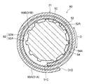
- FIG. 3 is a cross-sectional view taken along line 3X-3X in FIG. 1.
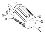
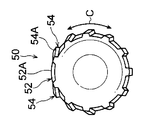
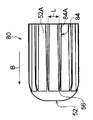
- It is a perspective view of the diameter expansion jig used with the manufacturing method of the heat exchanger of 1st Embodiment.
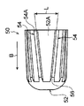
- It is a front view of the diameter expansion jig shown in FIG. 4A.
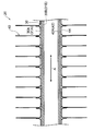
- It is a side view of the diameter expansion jig shown in FIG. 4A.
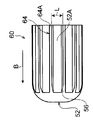
- FIG. 6A It is sectional drawing along the axial direction of the tubular body of the heat exchanger manufactured by the manufacturing method of the heat exchanger of 1st Embodiment. It is a perspective view of the 1st modification of a diameter expansion jig used in a 1st embodiment. It is a front view of the diameter expansion jig of the 1st modification shown in Drawing 6A. It is a side view of the diameter expansion jig of the 1st modification shown in Drawing 6A. It is a perspective view of the 2nd modification of a diameter expansion jig used in a 1st embodiment. It is a front view of the diameter expansion jig of the 2nd modification shown in Drawing 7A.
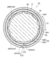
- FIG. 11 is a cross-sectional view taken along the axis perpendicular direction of the tubular body after diameter expansion for explaining the diameter expansion process of the manufacturing method of the heat exchanger of FIG. 10 (a view corresponding to the cross-sectional view taken along line 3X-3X in FIG. 1). .
- the heat exchanger 20 manufactured by the manufacturing method of the heat exchanger of 1st Embodiment is shown.
- the heat exchanger 20 of the present embodiment is mounted on an air conditioner and is used for heat exchange of a fluid used in a heat exchange unit of the air conditioner.
- this invention is not limited to the said structure,
- the heat exchanger 20 may be used for cooling of the refrigerant
- coolant an example of a fluid
- coolant an example of a fluid
- the cooling water of the engine cooling device (an example of fluid) may be used for cooling. That is, the heat exchanger 20 of the present embodiment may be applied to any device as long as it is an application for exchanging heat from a fluid.
- the heat transfer tube 30 is formed by bending a single metal plate 31. Specifically, the heat transfer tube 30 is formed by winding a metal plate 31 in a roll shape and joining the wound portions. Note that the heat transfer tube 30 of the present embodiment is a double-winding tube in which a metal plate 31 is double-wound.
- a part of the inner surface 31B of the metal plate 31 wound in a roll shape is a tube inner surface 30B, and a part of the outer surface 31A of the metal plate 31 wound in a roll shape is a tube outer surface 30A.
- an intermediate portion (intermediate portion in the winding direction) between the end portion 31C and the end portion 31D of the metal plate 31 wound in a roll shape is substantially crank-shaped.
- the step portion 32 is formed by being bent.
- One surface (surface constituting the inner surface 31B) of the stepped portion 32 formed in this way is an inner step surface 32B, and the other surface (surface constituting the outer surface 31A) is an outer step surface 32A.
- a flat metal plate 31 having a core material covered with a coating material is prepared, and the metal plate 31 is wound into a roll shape to form a heat transfer tube 30 (heat transfer tube before diameter expansion) which is an example of a tubular body.
- a heat transfer tube 30 heat transfer tube before diameter expansion
- the metal plate 31 is wound into a roll shape using a roll forming machine, that is, the heat transfer tube 30 is formed by roll forming (roll forming).
- the metal plate 31 is wound in a roll shape so that the outer diameter of the heat transfer tube 30 is smaller than the diameter of the through hole 42 formed in the fin 40 (see FIG. 1).
- the metal plate 31 wound in a roll shape is inserted into the through hole 42 formed in the fin 40. Thereafter, the metal plate 31 wound in a roll shape is loosened to expand the diameter of the heat transfer tube 30, and the tube outer surface 30 ⁇ / b> A of the heat transfer tube 30 and the hole wall 42 ⁇ / b> A of the through hole 42 of the fin 40 are brought into contact with each other.
- a diameter-enlarging jig 50 having an outer diameter larger than the inner diameter of the heat transfer tube 30 before diameter expansion is inserted into the heat transfer tube 30 before diameter expansion to form a roll.
- the heat transfer tube 30 is expanded in diameter by forcibly loosening the metal plate 31 wound around.
- the outer diameter of the diameter expansion jig 50 is set to a size that allows the heat transfer tube 30 to be expanded until the outer surface 30A of the tube comes into contact with the hole wall 42A.
- the rib 54 extends linearly toward the side opposite to the insertion direction of the main body 52. Further, the two ribs 54 arranged on both sides of the end portion 31C of the metal plate 31 wound in a roll shape have an interval L between the contact portions contacting the inner surface 30B of the heat transfer tube 30 as the main body. The portion 52 extends toward the opposite side of the insertion direction.
- the inclined portion 56 is configured such that the protruding height from the outer peripheral surface 52A of the main body 52 is gradually increased toward the side opposite to the insertion direction of the main body 52.
- the diameter expansion jig 50 having an outer diameter larger than the inner diameter of the heat transfer pipe 30 before diameter expansion is placed inside the heat transfer pipe 30 before diameter expansion.
- the metal plate 31 wound in a roll shape is forcibly loosened and the heat transfer tube 30 is expanded in diameter. That is, the heat transfer tube 30 can be easily expanded in diameter by using the diameter expansion jig 50 having an outer diameter larger than the inner diameter of the heat transfer tube 30 before the diameter expansion.
- the rib 54 of the diameter expansion jig 50 comes into contact with the tube inner surface 30B of the heat transfer tube 30, so that the contact area between the diameter expansion jig 50 and the tube inner surface 30B of the heat transfer tube 30 is reduced. It is possible to reduce resistance due to deformation of the heat transfer tube 30 when the diameter expansion jig 50 is inserted into the heat transfer tube 30. Thereby, the load required to insert the diameter expansion jig 50 into the heat transfer tube 30 can be reduced.
- each of the two ribs 54 disposed on both sides of the end portion 31C of the metal plate 31 wound in a roll shape comes into contact with the tube inner surface 30B of the heat transfer tube 30. Since the interval L between the contact portions is widened toward the side opposite to the insertion direction of the main body portion 52, when the diameter expansion jig 50 is inserted into the heat transfer tube 30, the two ribs 54 form a roll.
- the end 31C of the wound metal plate 31 receives a force in the direction opposite to the winding direction and moves in the circumferential direction of the heat transfer tube 30 (shown by the arrow D direction in the figure), and the metal plate 31 wound in a roll shape Relaxed. Thereby, the load required for the diameter expansion of the heat exchanger tube 30 can be made smaller.
- the diameter expansion jig 60 of the 1st modification, the diameter expansion jig 70 of the 2nd modification, and the diameter expansion jig 80 of the 3rd modification are manufacture of the heat exchanger 22 of 2nd Embodiment mentioned later. It may be used in the method.
- the rib 64 protruding from the outer peripheral surface 52A of the main body portion 52 has an insertion direction from the end side in the insertion direction of the main body portion 52. It extends linearly along the opposite direction.
- a plurality of ribs 64 are provided on the main body 52 at regular intervals in the circumferential direction. For this reason, when the diameter expansion jig 60 is inserted into the heat transfer tube 30 before the diameter expansion, the diameter expansion jig 60 is transferred before the diameter expansion without being limited by the position of the rib 64 of the diameter expansion jig 60. It can be inserted into the heat tube 30. Thereby, the complexity of the diameter expansion work of the heat exchanger tube 30 can be improved.
- 6A to 6C indicates the top of the rib 64.
- the metal plate 31 having the concavo-convex portion 92 formed on one plate surface is wound in a roll shape with the concavo-convex portion 92 inside, thereby forming a heat transfer tube 90 as an example of a tubular body (see FIG. 10).
- the diameter of the heat transfer tube 90 is increased by the diameter expansion jig 50.
- the deformation (collapse deformation) of the uneven portion 92 formed on the tube inner surface 90B can be suppressed. Thereby, the heat transfer efficiency between the heat transfer tube 90 and the fluid passing through the heat transfer tube 90 can be ensured.
Abstract
熱交換器の製造方法が、金属板(31)をロール状に巻いて伝熱管(30)を形成する形成工程と、金属製のフィン(40)に形成された貫通孔(42)に伝熱管(30)を挿入し、ロール状に巻かれた金属板(31)を弛めて伝熱管(30)を拡径させて、伝熱管(30)の管外面(30A)と貫通孔(42)の孔壁(42A)とを接触させる拡径工程と、拡径工程の後でロール状に巻かれた金属板(31)の巻き重ねられた部分を接合する接合工程と、を備える。
Description
本発明は、熱交換器の製造方法及び拡径治具に関する。
特開2011-257084号公報には、アルミニウムを管状に押し出して形成された管状体(伝熱管)をフィンに形成された挿入孔に挿入した後、管状体の内部に拡径治具(拡管治具)を挿入して該管状体の外径を拡げる方法について開示されている。
しかしながら、特開2011-257084号公報に開示の方法では、拡径治具で管3状体を周方向に延ばして(周長を延ばして)外径を広げるため、管状体の拡径に大きな荷重を必要とする。
本発明は、上記事実を考慮して、管状体の拡径に必要とされる荷重を小さくできる熱交換器の製造方法及び拡径治具を提供することを課題とする。
本発明の第1態様の熱交換器の製造方法は、金属板をロール状に巻いて管状体を形成する形成工程と、金属製のフィンに形成された貫通孔に前記管状体を挿入し、ロール状に巻かれた前記金属板を弛めて前記管状体を拡径させて、前記管状体の外周面と前記貫通孔の孔壁とを接触させる拡径工程と、拡径工程の後でロール状に巻かれた前記金属板の巻き重ねられた部分を接合する接合工程と、を備えている。
第1態様の熱交換器の製造方法では、金属板をロール状に巻いて管状体を形成し、このロール状に巻かれた金属板を弛めて管状体を拡径させるため、例えば、押し出しで形成された管状体を周方向に延ばして(周長を延ばして)拡径させる構成と比べて、管状体の拡径に必要とされる荷重を小さくできる。
本発明の第2態様の熱交換器の製造方法は、第1態様の熱交換器の製造方法において、前記拡径工程では、拡径前の前記管状体の内径よりも外径が大きい拡径治具を拡径前の前記管状体の内部に挿入してロール状に巻かれた前記金属板を強制的に弛めて前記管状体を拡径させる。
第2態様の熱交換器の製造方法では、拡径工程において、拡径前の管状体の内径よりも外径が大きい拡径治具を拡径前の管状体の内部に挿入するため、ロール状に巻かれた金属板が強制的に弛められて管状体が拡径される。すなわち、拡径前の管状体の内径よりも外径が大きい拡径治具を用いることで簡単に管状体を拡径することができる。
本発明の第3態様の熱交換器の製造方法は、第2態様の熱交換器の製造方法において、前記形成工程では、一方の板面に凹凸部が形成された前記金属板を、前記凹凸部を内側にしてロール状に巻いて前記管状体を形成する。
第3態様の熱交換器の製造方法では、一方の板面に形成された凹凸部を内側にして金属板をロール状に巻くため、内周面に凹凸部が形成された管状体が形成される。このように、凹凸部を形成することで、管状体の内周面の表面積が増えて、管状体と管状体の内部を通る流体との間の熱伝達効率が向上する。
ここで、上記熱交換器の製造方法では、前述のように管状体の拡径に必要とされる荷重を小さくできるため、拡径治具で管状体を拡径させるときに、管状体の内周面に形成された凹凸部の変形(潰れ変形)を抑制できる。これにより、管状体と管状体の内部を通る流体との間の熱伝達効率を確保することができる。
ここで、上記熱交換器の製造方法では、前述のように管状体の拡径に必要とされる荷重を小さくできるため、拡径治具で管状体を拡径させるときに、管状体の内周面に形成された凹凸部の変形(潰れ変形)を抑制できる。これにより、管状体と管状体の内部を通る流体との間の熱伝達効率を確保することができる。
本発明の第4態様の熱交換器の製造方法は、第2態様又は第3態様の熱交換器の製造方法において、前記金属板は、アルミニウムで構成されている。
第4態様の熱交換器の製造方法では、アルミニウムで構成された金属板をロール状に巻いて管状体を形成するため、管状体と管状体の内部を通る流体との間の熱伝達効率を確保しつつ、重量を軽減し且つコストを削減することができる。また、金属板をアルミニウムで構成するため、例えば、金属板を鉄板などの変形しにくい材料で構成したものと比べて、管状体の拡径に必要とされる荷重を小さくできる。また、拡径治具で管状体を拡径させるときの、管状体の内周面に形成された凹凸部の変形(潰れ変形)をさらに抑制できる。
本発明の第5態様の熱交換器の製造方法は、第2態様~第4態様のいずれか一態様に記載の熱交換器の製造方法において、前記拡径治具は、前記管状体の内部に挿入される円柱状の本体部と、前記本体部の外周面に周方向に間隔をあけて設けられ、前記本体部の外周面から突出すると共に前記本体部の挿入方向の端部側から前記挿入方向と反対側に延び、前記管状体の内周面に接触するリブと、前記リブの前記挿入方向の先端部に形成され、前記挿入方向と反対側に向かって前記本体部の外周面からの突出高さが次第に高くなる傾斜部と、を含んで構成されている。
第5態様の熱交換器の製造方法では、拡径治具を構成するリブが管状体の内周面に接触することから、拡径治具と管状体の内周面との接触面積を小さくできるため、拡径治具を管状体に挿入するときの管状体の変形による抵抗を軽減できる。これにより、拡径治具を管状体に挿入するのに必要とされる荷重を小さくできる。
また、リブの挿入方向の先端部に、挿入方向と反対側に向かって本体部の外周面からの突出高さが次第に高くなる傾斜部を形成していることから、例えば、傾斜部を有さないリブ構成と比べて、拡径前の管状体に拡径治具を挿入するときに傾斜部が管状体を拡径させるためのガイドとなり、拡径治具を管状体にスムーズに挿入することができる。
本発明の第6態様の熱交換器の製造方法は、第5態様の熱交換器の製造方法において、前記リブは、前記本体部の前記挿入方向と反対側に向かって螺旋状に延び且つ螺旋の向きがロール状に巻かれた前記金属板の巻き方向と逆向きとされている。
第6態様の熱交換器の製造方法では、リブを本体部の挿入方向と反対側に向かって、螺旋の向きがロール状に巻かれた金属板の巻き方向と逆向きとなるように螺旋状に延ばしていることから、管状体に拡径治具を挿入していくと、リブによってロール状に巻かれた金属板が巻き方向と逆向きの力を受けて弛められる。これにより、管状体の拡径に必要とされる荷重をより小さくできる。
本発明の第7態様の熱交換器の製造方法は、第5態様の熱交換器の製造方法において、前記リブは、前記本体部の前記挿入方向と反対側に向かって直線状に延び、ロール状に巻かれた前記金属板の内周側の端部を挟んで両側に配置される2本のリブは、前記管状体の内周面と接触するそれぞれの接触部分間の間隔が前記挿入方向と反対側に向かって広がっている。
第7態様の熱交換器の製造方法では、ロール状に巻かれた金属板の内周側の端部を挟んで両側に配置される2本のリブの管状体の内周面と接触するそれぞれの接触部分間の間隔を挿入方向と反対側に向かって広げていることから、管状体に拡径治具を挿入していくと、2本のリブによって、ロール状に巻かれた金属板の内周側の端部が巻き方向と逆向きの力を受けて管状体の周方向に移動し、ロール状に巻かれた金属板が弛められる。これにより、管状体の拡径に必要とされる荷重をより小さくできる。
本発明の第8態様の拡径治具は、金属板をロール状に巻いて形成された管状体を拡径させるための拡径治具であって、前記管状体の内部に挿入される円柱状の本体部と、前記本体部の外周面に周方向に間隔をあけて設けられ、前記本体部の外周面から突出すると共に前記本体部の挿入方向の端部側から前記挿入方向と反対側に延び、前記管状体の内周面に接触するリブと、前記リブの前記挿入方向の先端部に形成され、前記挿入方向と反対側に向かって前記本体部の外周面からの突出高さが次第に高くなる傾斜部と、を備え、前記管状体の内径よりも外径が大きくされている。
第8態様の拡径治具では、管状体の内径よりも外径を大きくしているため、管状体の内部に挿入することでロール状に巻かれた金属板が強制的に弛められて管状体が拡径する。ここで、拡径治具の挿入時には、リブが管状体の内周面に接触することから、拡径治具と管状体の内周面との接触面積を小さくできる。このため、拡径治具を管状体に挿入するときの管状体の変形による抵抗を軽減できる。これにより、拡径治具を管状体に挿入するのに必要とされる荷重を小さくできる。結果、管状体の拡径に必要とされる荷重を小さくできる。
以上説明したように、本発明の熱交換器の製造方法及び拡径治具は、管状体の拡径に必要とされる荷重を小さくできる。
本発明に係る熱交換器の製造方法及び拡径治具の一実施形態について図面を参照しながら説明する。
(第1実施形態)
図5には、第1実施形態の熱交換器の製造方法によって製造される熱交換器20を示している。本実施形態の熱交換器20は、空調機器に搭載され、該空調機器の熱交換部で使用する流体の熱交換に用いられる。なお、本発明は上記構成に限定されず、熱交換器20は、冷蔵庫などに搭載されて冷蔵庫の冷却部で使用する冷媒(流体の一例)の冷却に用いられてもよく、自動車に搭載されてエンジン冷却装置の冷却水(流体の一例)の冷却に用いられてもよい。つまり、本実施形態の熱交換器20は、流体を熱交換する用途であれば、いずれの機器に適用してもよい。
図5には、第1実施形態の熱交換器の製造方法によって製造される熱交換器20を示している。本実施形態の熱交換器20は、空調機器に搭載され、該空調機器の熱交換部で使用する流体の熱交換に用いられる。なお、本発明は上記構成に限定されず、熱交換器20は、冷蔵庫などに搭載されて冷蔵庫の冷却部で使用する冷媒(流体の一例)の冷却に用いられてもよく、自動車に搭載されてエンジン冷却装置の冷却水(流体の一例)の冷却に用いられてもよい。つまり、本実施形態の熱交換器20は、流体を熱交換する用途であれば、いずれの機器に適用してもよい。
図5に示されるように、本実施形態の熱交換器20は、伝熱管30とフィン40とを備えている。なお、本実施形態の伝熱管30は、本発明の管状体の一例である。
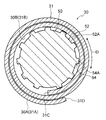
図2及び図3に示されるように、伝熱管30は、一枚の金属板31を曲げ加工して形成されている。具体的には、伝熱管30は、金属板31をロール状に巻き且つ巻き重ねられた部分を接合して形成されている。なお、本実施形態の伝熱管30は、金属板31を二重巻きした二重巻管である。この伝熱管30は、ロール状に巻かれた金属板31の内面31Bの一部分が管内面30Bとされ、ロール状に巻かれた金属板31の外面31Aの一部分が管外面30Aとされている。なお、管外面30Aは、伝熱管30の外周面を示し、管内面30Bは、伝熱管30の内周面を示している。また、伝熱管30の軸方向を図中矢印A方向で示している。
ロール状に巻かれた金属板31の内面31Bには、内周側の端部31Cと外周側の端部31Dとの間に内側段差面32Bが形成されている。この内側段差面32Bには、ロール状に巻かれた金属板31の端部31Cが接合されている。
一方、ロール状に巻かれた金属板31の外面31Aには、端部31Cと端部31Dとの間に外側段差面32Aが形成されている。この外側段差面32Aには、ロール状に巻かれた金属板31の端部31Dが接合されている。
なお、本実施形態では、後述する熱交換器20の製造方法において、ロール状に巻かれた金属板31の端部31Cと端部31Dとの中間部分(巻き方向の中間部分)が略クランク状に曲げられて段差部32が形成される。このように形成された段差部32の一方の面(内面31Bを構成する面)を内側段差面32Bとし、他方の面(外面31Aを構成する面)を外側段差面32Aとしている。
伝熱管30を形成する金属板31には、金属材料で形成された芯材に、この芯材よりも融点の低い金属材料で形成された被覆材を張り合わせて形成された金属板、すなわち、クラッド板を用いている。本実施形態では、金属板31をアルミニウムで構成している。具体的には、金属板31は、純アルミニウムで形成された芯材に、アルミニウム合金(例えば、アルミニウムにシリコンを含有させたもの)で形成された被覆材を張り合わせて形成されている。この被覆材は、ロール状に巻かれた金属板31の外面31Aを形成している。また、被覆材は、ロール状に巻かれた金属板31の巻き重ねられた部分を接合する接合材(ろう材)として用いられている。一方、芯材は、ロール状に巻かれた金属板31の内面31Bを形成している。
なお、本実施形態では、金属板31をアルミニウムで構成しているが、本発明はこの構成に限定されず、金属板31を銅や鉄などの金属材料で構成してもよい。
図5に示されるように、フィン40は、金属材料(例えば、アルミニウム)を板状に形成したものである。このフィン40には、板厚方向に貫通する貫通孔42が形成されている。具体的には、フィン40には、バーリング加工によって貫通孔42が形成されている。この貫通孔42には、伝熱管30が挿入されると共に孔壁42Aに伝熱管30の外周面である管外面30Aが接合されている。なお、本実施形態では、フィン40にバーリング加工によって形成された環状の立ち上がり部44の内壁である孔壁42Aに伝熱管30の管外面30Aが接合されている。
次に、熱交換器20について詳細に説明する。熱交換器20では、複数本の伝熱管30が互いに平行に並べられ、隣接する伝熱管30の端部同士がU字状の管継手で連結されている。また、各伝熱管30は、複数枚のフィン40の各貫通孔42にそれぞれ挿入されると共に各孔壁42Aに各管外面30Aがそれぞれ接合されている。
次に本発明の第1実施形態に係る熱交換器20の製造方法について説明する。
(形成工程)
まず、芯材に被覆材を張り合わせた平板状の金属板31を用意し、この金属板31をロール状に巻いて管状体の一例である伝熱管30(拡径前の伝熱管)を形成する(図2参照)。具体的には、ロール成形機を用いて金属板31をロール状に巻く、すなわち、ロール成形(ロールフォーミング)して伝熱管30を形成する。この形成工程では、伝熱管30の外径がフィン40に形成された貫通孔42の直径よりも小さくなるように金属板31をロール状に巻いている(図1参照)。
(形成工程)
まず、芯材に被覆材を張り合わせた平板状の金属板31を用意し、この金属板31をロール状に巻いて管状体の一例である伝熱管30(拡径前の伝熱管)を形成する(図2参照)。具体的には、ロール成形機を用いて金属板31をロール状に巻く、すなわち、ロール成形(ロールフォーミング)して伝熱管30を形成する。この形成工程では、伝熱管30の外径がフィン40に形成された貫通孔42の直径よりも小さくなるように金属板31をロール状に巻いている(図1参照)。
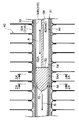
(拡径工程)
次に、フィン40に形成された貫通孔42にロール状に巻かれた金属板31を挿入する。その後、ロール状に巻かれた金属板31を弛めて伝熱管30を拡径させて、伝熱管30の管外面30Aとフィン40の貫通孔42の孔壁42Aとを接触させる。具体的には、図1に示されるように、拡径前の伝熱管30の内径よりも外径が大きい拡径治具50を拡径前の伝熱管30の内部に挿入して、ロール状に巻かれた金属板31を強制的に弛めて伝熱管30を拡径させている。この拡径治具50の外径は、管外面30Aが孔壁42Aに接触するまで伝熱管30を拡径させられる大きさに設定されている。
次に、フィン40に形成された貫通孔42にロール状に巻かれた金属板31を挿入する。その後、ロール状に巻かれた金属板31を弛めて伝熱管30を拡径させて、伝熱管30の管外面30Aとフィン40の貫通孔42の孔壁42Aとを接触させる。具体的には、図1に示されるように、拡径前の伝熱管30の内径よりも外径が大きい拡径治具50を拡径前の伝熱管30の内部に挿入して、ロール状に巻かれた金属板31を強制的に弛めて伝熱管30を拡径させている。この拡径治具50の外径は、管外面30Aが孔壁42Aに接触するまで伝熱管30を拡径させられる大きさに設定されている。
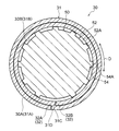
また、伝熱管30の拡径時には、図3に示されるように、ロール状に巻かれた金属板31の端部31Cと端部31Dとの間に段差部32が形成される。このとき、段差部32の内側段差面32Bには、端部31Cが対向配置され、段差部32の外側段差面32Aには、端部31Dが対向配置される。
(接合工程)
次に、ロール状に巻かれた金属板31とフィン40を加熱して被覆材を溶融させ、ロール状に巻かれた金属板31の巻き重ねられた部分を密着させた状態で被覆材を冷却固化させてロール状に巻かれた金属板31の巻き重ねられた部分を接合(ろう付け)する。このとき、ロール状に巻かれた金属板31の外周を形成する被覆材と貫通孔42の孔壁42Aも接合される。これにより、熱交換器20が形成される。
次に、ロール状に巻かれた金属板31とフィン40を加熱して被覆材を溶融させ、ロール状に巻かれた金属板31の巻き重ねられた部分を密着させた状態で被覆材を冷却固化させてロール状に巻かれた金属板31の巻き重ねられた部分を接合(ろう付け)する。このとき、ロール状に巻かれた金属板31の外周を形成する被覆材と貫通孔42の孔壁42Aも接合される。これにより、熱交換器20が形成される。
次に本実施形態の熱交換器20の製造方法で用いる拡径治具50について説明する。
図1及び図4A~図4Cに示されるように、拡径治具50は、伝熱管30の内部に挿入される円柱状の本体部52と、本体部52の外周面52Aに設けられたリブ54と、リブ54の挿入方向の先端部に形成された傾斜部56と、を含んで構成されている。なお、本体部52の挿入方向と拡径治具50の挿入方向は同じ方向であり、本体部52の挿入方向を図中矢印B方向で示している。
図1及び図4A~図4Cに示されるように、拡径治具50は、伝熱管30の内部に挿入される円柱状の本体部52と、本体部52の外周面52Aに設けられたリブ54と、リブ54の挿入方向の先端部に形成された傾斜部56と、を含んで構成されている。なお、本体部52の挿入方向と拡径治具50の挿入方向は同じ方向であり、本体部52の挿入方向を図中矢印B方向で示している。
リブ54は、本体部52の外周面52Aから突出すると共に本体部52の挿入方向の端部側から該挿入方向と反対側に延びている。また、リブ54は、本体部52に円周方向(図中矢印C方向で示す)に間隔をあけて複数設けられている。このリブ54は、頂部54Aが伝熱管30の管内面30Bに接触するように構成されている。なお、前述の拡径治具50の外径は、本体部52の中心軸から最も離間したリブ54の部位(頂部54Aの一部)を通る円の外径を示している。
また、リブ54は、本体部52の挿入方向と反対側に向かって直線状に延びている。また、ロール状に巻かれた金属板31の端部31Cを挟んで両側に配置される2本のリブ54は、伝熱管30の管内面30Bと接触するそれぞれの接触部分間の間隔Lが本体部52の挿入方向と反対側に向かって広がっている。
傾斜部56は、本体部52の挿入方向と反対側に向かって本体部52の外周面52Aからの突出高さが次第に高くなるように構成されている。
また、拡径治具50には、本体部52を伝熱管30の内部に挿入するための駆動装置から延びるロッド58が連結されている。
次に本実施形態の熱交換器20の製造方法の作用効果について説明する。
本実施形態の熱交換器20の製造方法では、金属板31をロール状に巻いて伝熱管30を形成し、このロール状に巻かれた金属板31を弛めて伝熱管30を拡径させるため、例えば、押し出しで形成された押出伝熱管を周方向に延ばして(周長を延ばして)拡径させる構成と比べて、伝熱管30の拡径に必要とされる荷重を小さくできる。
本実施形態の熱交換器20の製造方法では、金属板31をロール状に巻いて伝熱管30を形成し、このロール状に巻かれた金属板31を弛めて伝熱管30を拡径させるため、例えば、押し出しで形成された押出伝熱管を周方向に延ばして(周長を延ばして)拡径させる構成と比べて、伝熱管30の拡径に必要とされる荷重を小さくできる。
具体的には、熱交換器20の製造方法では、拡径工程において、拡径前の伝熱管30の内径よりも外径が大きい拡径治具50を拡径前の伝熱管30の内部に挿入するため、ロール状に巻かれた金属板31が強制的に弛められて伝熱管30が拡径される。すなわち、拡径前の伝熱管30の内径よりも外径が大きい拡径治具50を用いることで簡単に伝熱管30を拡径することができる。
また、伝熱管30の拡径時には、拡径治具50のリブ54が伝熱管30の管内面30Bに接触するため、拡径治具50と伝熱管30の管内面30Bとの接触面積を小さくでき、拡径治具50を伝熱管30に挿入するときの伝熱管30の変形による抵抗を軽減できる。これにより、拡径治具50を伝熱管30に挿入するのに必要とされる荷重を小さくできる。
また、リブ54の本体部52の挿入方向の先端部に、該挿入方向と反対側に向かって本体部52の外周面52Aからの突出高さが次第に高くなる傾斜部56を形成していることから、拡径前の伝熱管30に拡径治具50を挿入するときに傾斜部56が伝熱管30を拡径させるためのガイドとなる。これにより、拡径治具50を伝熱管30にスムーズに挿入することができる。
またさらに、伝熱管30の拡径時には、ロール状に巻かれた金属板31の端部31Cを挟んで両側に配置される2本のリブ54の伝熱管30の管内面30Bと接触するそれぞれの接触部分間の間隔Lを本体部52の挿入方向と反対側に向かって広げていることから、伝熱管30に拡径治具50を挿入していくと、2本のリブ54によってロール状に巻かれた金属板31の端部31Cが巻き方向と逆向きの力を受けて伝熱管30の周方向(図中矢印D方向で示す)に移動し、ロール状に巻かれた金属板31が弛められる。これにより、伝熱管30の拡径に必要とされる荷重をより小さくできる。
また、熱交換器20の製造方法では、アルミニウムで構成された金属板31をロール状に巻いて伝熱管30を形成するため、伝熱管30とこの伝熱管30の内部を通る流体との間の熱伝達効率を確保しつつ、熱交換器20の重量を軽減し且つコストを削減することができる。また、金属板31をアルミニウムで構成するため、例えば、金属板31を鉄板などの変形しにくい材料で構成したものと比べて、伝熱管30の拡径に必要とされる荷重を小さくできる。
本実施形態では、金属板31をロール状に巻いて形成された伝熱管30を拡径治具50で拡径する構成としているが、本発明はこの構成に限定されない。例えば、以下に示す拡径治具50の第1変形例である拡径治具60、第2変形例である拡径治具70、第3変形例である拡径治具80などを用いて伝熱管30を拡径する構成としてもよい。なお、第1変形例の拡径治具60、第2変形例の拡径治具70、及び第3変形例の拡径治具80は、後述する第2実施形態の熱交換器22の製造方法に用いてもよい。
図6A~図6Cに示されるように、第1変形例の拡径治具60は、本体部52の外周面52Aから突出するリブ64が本体部52の挿入方向の端部側から該挿入方向と反対方向に沿って直線状に延びている。また、リブ64は、本体部52に円周方向に一定間隔をあけて複数設けられている。このため、拡径治具60を拡径前の伝熱管30に挿入する際に、拡径治具60のリブ64の位置に制限を受けずに、拡径治具60を拡径前の伝熱管30に挿入することができる。これにより、伝熱管30の拡径作業の煩雑さを改良することができる。なお、図6A~図6C中の符号64Aは、リブ64の頂部を示している。
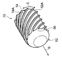
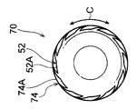
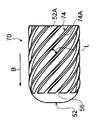
図7A~図7Cに示されるように、第2変形例の拡径治具70は、本体部52の外周面52Aから突出するリブ74が本体部52の挿入方向の端部側から該挿入方向と反対側に向かって螺旋状に延びている(具体的には、本体部52の外周面52Aに沿って螺旋状に延びている)。また、リブ74の螺旋の向きは、ロール状に巻かれた金属板31の巻き方向と逆向きとされている。さらに、リブ74は、本体部52に円周方向に一定間隔をあけて複数設けられている。ここで、伝熱管30に拡径治具70を挿入していくと、螺旋状のリブ74によってロール状に巻かれた金属板31が巻き方向と逆向きの力を受けて弛められる。これにより、伝熱管30の拡径に必要とされる荷重をより小さくできる。なお、図7A~図7C中の符号74Aは、リブ74の頂部を示している。
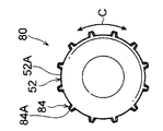
図8A~図8Cに示されるように、第3変形例の拡径治具80は、本体部52の外周面52Aから突出するリブ84が本体部52の挿入方向の端部側から該挿入方向と反対方向に沿って直線状に延びている。また、リブ84は、本体部52の挿入方向の反対側に向かって頂部84Aの幅(本体部52の円周方向に沿った長さ)が次第に広くなっている。ここで、拡径治具80を拡径前の伝熱管30に挿入する際には、まず、リブ84の頂部84Aの幅が狭い部分が伝熱管30の管内面30Bに接触するため、伝熱管30の変形による抵抗が低く、挿入に必要な荷重を小さくできる。その後、頂部84Aの幅が広い部分が伝熱管30の管外面30Aに接触するため、伝熱管30の管内面30Bを周上略均等に拡径することができる。
(第2実施形態)
図9には、第2実施形態の熱交換器の製造方法によって製造される熱交換器22の伝熱管90を示している。なお、本実施形態では、第1実施形態と同一の構成については同一符号を付し、その説明を省略する。
図9には、第2実施形態の熱交換器の製造方法によって製造される熱交換器22の伝熱管90を示している。なお、本実施形態では、第1実施形態と同一の構成については同一符号を付し、その説明を省略する。
本実施形態の熱交換器22は、伝熱管90の構成を除いて、第1実施形態の熱交換器20と同一の構成である。
図9に示されるように、伝熱管90は、内周面(以下、「管内面90B」と記載する)に凹凸部92が形成されている。この凹凸部92は、管内面90Bの略全体に形成されている。なお、本実施形態の伝熱管90は、本発明の管状体の一例である。
また、伝熱管90は、凹凸部92が形成された金属板31をロール状に巻き且つ巻き重ねられた部分を接合して形成されている。なお、本実施形態の伝熱管90は、金属板31を二重巻きした二重巻管である。この伝熱管90は、ロール状に巻かれた金属板31の内面31Bの一部分が管内面90Bとされ、ロール状に巻かれた金属板31の外面31Aの一部分が管外面90Aとされている。なお、金属板31は、凹凸部92が形成される構成以外は第1実施形態と同じ構成である。
図9に示されるように、凹凸部92は、伝熱管90の周方向に間隔をあけて形成され、伝熱管90の軸方向に対して交差する方向(本実施形態では、傾斜する方向)に延び、伝熱管90の半径方向外側へ凹む溝部92Aと、隣接する溝部92A間に形成され、伝熱管90の半径方向内側へ凸となる突条部92Bとで構成されている。なお、本発明の凹凸部は、上記構成に限定されない。例えば、管内面90Bに複数の凸部又は複数の凹部を形成して凹凸部を構成してもよい。
次に第2実施形態の熱交換器22の製造方法について説明する。
(形成工程)
まず、芯材に被覆材を張り合わせた平板状の金属板31を用意し、この金属板31の一方の板面(芯材によって形成される板面)に凹凸部92を形成する。なお、凹凸部92は、金属板31の一方の板面の管内面90Bに対応する範囲に形成する。
(形成工程)
まず、芯材に被覆材を張り合わせた平板状の金属板31を用意し、この金属板31の一方の板面(芯材によって形成される板面)に凹凸部92を形成する。なお、凹凸部92は、金属板31の一方の板面の管内面90Bに対応する範囲に形成する。
次に、一方の板面に凹凸部92が形成された金属板31を、凹凸部92を内側にしてロール状に巻いて管状体の一例である伝熱管90を形成する(図10参照)。
次に、図10及び図11に示されるように、拡径治具50を用いて第1実施形態と同様の拡径工程を実施し、伝熱管90を拡径する。
そして、第1実施形態と同様の接合工程を実施して本実施形態の熱交換器22を形成する。
そして、第1実施形態と同様の接合工程を実施して本実施形態の熱交換器22を形成する。
次に本実施形態の熱交換器22の製造方法の作用効果について説明する。
熱交換器22の製造方法では、一方の板面に形成された凹凸部92を内側にして金属板31をロール状に巻くため、管内面90Bに凹凸部92が形成された伝熱管90が形成される。このように、凹凸部92を形成することで、伝熱管90の管内面90Bの表面積が増えて、伝熱管90とこの伝熱管90の内部を通る流体との間の熱伝達効率が向上する。
ここで、上記熱交換器22の製造方法では、第1実施形態と同様に伝熱管90の拡径に必要とされる荷重を小さくできるため、拡径治具50で伝熱管90を拡径させるときに、管内面90Bに形成された凹凸部92の変形(潰れ変形)を抑制できる。これにより、伝熱管90とこの伝熱管90の内部を通る流体との間の熱伝達効率を確保することができる。
第1実施形態では、拡径工程で金属板31に段差部32が形成されるが、本発明はこの構成に限定されない。例えば、拡径工程の前に金属板31に段差部32をあらかじめ形成する構成としてもよい。なお、拡径工程の前に金属板31に段差部32をあらかじめ形成する構成については、第2実施形態に適用してもよい。
また、第1実施形態では、金属板31を芯材と被覆材で構成されたクラッド板としているが、本発明はこの構成に限定されず、金属板31を芯材のみの金属板としてもよい。この場合には、拡径後の伝熱管30の金属板31を巻き重ねた部分の隙間に溶融した接合材(ろう材)を注入することで上記金属板31の巻き重ねた部分を接合することができる。また、フィン40の片面又は両面をアルミニウム合金(ろう材)で形成し、拡径後の伝熱管30と共に加熱して、溶融したアルミニウム合金で上記金属板31の巻き重ねた部分を接合してもよい。なお、上記構成については、第2実施形態に適用してもよい。
第1実施形態では、伝熱管30を、金属板31を二重巻した二重巻管としているが、本発明は、この構成に限定されず、金属板31を二重よりも多く巻いた多重巻管としてもよい。なお、上記構成については、第2実施形態の伝熱管90に適用してもよい。
以上、実施形態を挙げて本発明の実施の形態を説明したが、これらの実施形態は一例であり、要旨を逸脱しない範囲内で種々変更して実施できる。また、本発明の権利範囲がこれらの実施形態に限定されないことは言うまでもない。
なお、2014年1月29日に出願された日本国特許出願2014-014650号の開示は、その全体が参照により本明細書に取り込まれる。
本明細書に記載された全ての文献、特許出願、および技術規格は、個々の文献、特許出願、および技術規格が参照により取り込まれることが具体的かつ個々に記された場合と同程度に、本明細書中に参照により取り込まれる。
本明細書に記載された全ての文献、特許出願、および技術規格は、個々の文献、特許出願、および技術規格が参照により取り込まれることが具体的かつ個々に記された場合と同程度に、本明細書中に参照により取り込まれる。
Claims (8)
- 金属板をロール状に巻いて管状体を形成する形成工程と、
金属製のフィンに形成された貫通孔に前記管状体を挿入し、ロール状に巻かれた前記金属板を弛めて前記管状体を拡径させて、前記管状体の外周面と前記貫通孔の孔壁とを接触させる拡径工程と、
拡径工程の後でロール状に巻かれた前記金属板の巻き重ねられた部分を接合する接合工程と、
を備える熱交換器の製造方法。 - 前記拡径工程では、拡径前の前記管状体の内径よりも外径が大きい拡径治具を拡径前の前記管状体の内部に挿入してロール状に巻かれた前記金属板を強制的に弛めて前記管状体を拡径させる、請求項1に記載の熱交換器の製造方法。
- 前記形成工程では、一方の板面に凹凸部が形成された前記金属板を、前記凹凸部を内側にしてロール状に巻いて前記管状体を形成する、請求項2に記載の熱交換器の製造方法。
- 前記金属板は、アルミニウムで構成されている、請求項2又は請求項3に記載の熱交換器の製造方法。
- 前記拡径治具は、前記管状体の内部に挿入される円柱状の本体部と、前記本体部の外周面に周方向に間隔をあけて設けられ、前記本体部の外周面から突出すると共に前記本体部の挿入方向の端部側から前記挿入方向と反対側に延び、前記管状体の内周面に接触するリブと、前記リブの前記挿入方向の先端部に形成され、前記挿入方向と反対側に向かって前記本体部の外周面からの突出高さが次第に高くなる傾斜部と、を含んで構成されている、請求項2~4のいずれか1項に記載の熱交換器の製造方法。
- 前記リブは、前記本体部の前記挿入方向と反対側に向かって螺旋状に延び且つ螺旋の向きがロール状に巻かれた前記金属板の巻き方向と逆向きとされている、請求項5に記載の熱交換器の製造方法。
- 前記リブは、前記本体部の前記挿入方向と反対側に向かって直線状に延び、
ロール状に巻かれた前記金属板の内周側の端部を挟んで両側に配置される2本のリブは、前記管状体の内周面と接触するそれぞれの接触部分間の間隔が前記挿入方向と反対側に向かって広がっている、請求項5に記載の熱交換器の製造方法。 - 金属板をロール状に巻いて形成された管状体を拡径させるための拡径治具であって、
前記管状体の内部に挿入される円柱状の本体部と、
前記本体部の外周面に周方向に間隔をあけて設けられ、前記本体部の外周面から突出すると共に前記本体部の挿入方向の端部側から前記挿入方向と反対側に延び、前記管状体の内周面に接触するリブと、
前記リブの前記挿入方向の先端部に形成され、前記挿入方向と反対側に向かって前記本体部の外周面からの突出高さが次第に高くなる傾斜部と、
を備え、前記管状体の内径よりも外径が大きくされた拡径治具。
Priority Applications (3)
| Application Number | Priority Date | Filing Date | Title |
|---|---|---|---|
| DE112014006290.1T DE112014006290T5 (de) | 2014-01-29 | 2014-10-15 | Wärmetauscher-Herstellverfahren und Durchmesser-Vergrößerungswerkzeug |
| CN201480074426.XA CN105939797A (zh) | 2014-01-29 | 2014-10-15 | 热交换器的制造方法以及扩径治具 |
| US15/115,069 US20160361749A1 (en) | 2014-01-29 | 2014-10-15 | Heat exchanger manufacturing method and diameter enlargement tool |
Applications Claiming Priority (2)
| Application Number | Priority Date | Filing Date | Title |
|---|---|---|---|
| JP2014-014650 | 2014-01-29 | ||
| JP2014014650A JP6327868B2 (ja) | 2014-01-29 | 2014-01-29 | 熱交換器の製造方法 |
Publications (1)
| Publication Number | Publication Date |
|---|---|
| WO2015114888A1 true WO2015114888A1 (ja) | 2015-08-06 |
Family
ID=53756488
Family Applications (1)
| Application Number | Title | Priority Date | Filing Date |
|---|---|---|---|
| PCT/JP2014/077473 WO2015114888A1 (ja) | 2014-01-29 | 2014-10-15 | 熱交換器の製造方法及び拡径治具 |
Country Status (6)
| Country | Link |
|---|---|
| US (1) | US20160361749A1 (ja) |
| JP (1) | JP6327868B2 (ja) |
| CN (1) | CN105939797A (ja) |
| AR (1) | AR099736A1 (ja) |
| DE (1) | DE112014006290T5 (ja) |
| WO (1) | WO2015114888A1 (ja) |
Cited By (1)
| Publication number | Priority date | Publication date | Assignee | Title |
|---|---|---|---|---|
| CN106040904A (zh) * | 2016-07-28 | 2016-10-26 | 海信(广东)空调有限公司 | 一种管翅式换热器的生产方法及管翅式换热器 |
Families Citing this family (7)
| Publication number | Priority date | Publication date | Assignee | Title |
|---|---|---|---|---|
| CN108067562B (zh) * | 2016-11-14 | 2019-06-07 | 丹佛斯微通道换热器(嘉兴)有限公司 | 换热器的组装方法 |
| JP7154747B2 (ja) * | 2016-11-25 | 2022-10-18 | 株式会社デンソーエアクール | 熱交換器および熱交換器の製造方法 |
| EP3702715A4 (en) * | 2017-10-27 | 2021-11-24 | China Petroleum & Chemical Corporation | IMPROVED HEAT TRANSFER PIPE, AS WELL AS PYROLYSIS OVEN AND ATMOSPHERIC AND VACUUM HEATING OVEN INCLUDING THIS |
| JP6913657B2 (ja) * | 2018-07-26 | 2021-08-04 | 三桜工業株式会社 | 多重巻管の成形装置及び多重巻管の成形方法 |
| JP7243104B2 (ja) * | 2018-09-27 | 2023-03-22 | 株式会社ノーリツ | 熱交換器およびその製造方法 |
| US11835306B2 (en) * | 2021-03-03 | 2023-12-05 | Rheem Manufacturing Company | Finned tube heat exchangers and methods for manufacturing same |
| CN114871532B (zh) * | 2022-07-11 | 2022-10-11 | 四川空分设备(集团)有限责任公司 | 一种换热管与管板手工深孔焊方法 |
Citations (5)
| Publication number | Priority date | Publication date | Assignee | Title |
|---|---|---|---|---|
| JPS55130351A (en) * | 1979-03-30 | 1980-10-09 | Mitsubishi Electric Corp | Production of heat exchange pipe |
| JPS6152948A (ja) * | 1984-08-23 | 1986-03-15 | Mitsubishi Heavy Ind Ltd | 内面溝付管の製造方法 |
| JPH04253534A (ja) * | 1991-01-31 | 1992-09-09 | Showa Alum Corp | 熱交換器用チューブの拡管方法 |
| JP2013202615A (ja) * | 2012-03-27 | 2013-10-07 | Mitsubishi Electric Corp | 拡管ビレット、拡管装置、及び熱交換器 |
| WO2014010387A1 (ja) * | 2012-07-13 | 2014-01-16 | 住友軽金属工業株式会社 | 拡管用プラグ |
Family Cites Families (11)
| Publication number | Priority date | Publication date | Assignee | Title |
|---|---|---|---|---|
| JPS5151557U (ja) * | 1974-10-18 | 1976-04-19 | ||
| JPS5151557A (en) * | 1974-10-30 | 1976-05-07 | Imamura Seisakusho Kk | Keekinadono hikansotaino kansoho |
| GB8625169D0 (en) * | 1986-10-21 | 1986-11-26 | Duma Packaging As | Closure assembly |
| JPS63138962U (ja) * | 1987-02-26 | 1988-09-13 | ||
| BE1005554A3 (fr) * | 1991-12-10 | 1993-10-26 | Bundy Internat Ltd | Procede de fabrication d'un tube a paroi multiple. |
| JP3164272B2 (ja) * | 1994-02-02 | 2001-05-08 | ディン カーン | ヒートパイプの製造方法およびその製造に用いる加工具 |
| JP3784626B2 (ja) * | 2000-09-20 | 2006-06-14 | 住友軽金属工業株式会社 | 内面溝付伝熱管を用いた熱交換器の製作方法 |
| CN1317540C (zh) * | 2002-03-18 | 2007-05-23 | 住友轻金属工业株式会社 | 使用内壁带槽的传热管的热交换器的制作方法 |
| JP4597475B2 (ja) * | 2002-12-12 | 2010-12-15 | 住友軽金属工業株式会社 | 熱交換器用クロスフィンチューブの製造方法及びクロスフィン型熱交換器 |
| JP4297794B2 (ja) * | 2003-02-20 | 2009-07-15 | 三菱電機株式会社 | 熱交換器の拡管装置 |
| US20070205001A1 (en) * | 2003-09-05 | 2007-09-06 | Eventure Global Technology, Llc | Expandable Tubular |
-
2014
- 2014-01-29 JP JP2014014650A patent/JP6327868B2/ja not_active Expired - Fee Related
- 2014-10-15 WO PCT/JP2014/077473 patent/WO2015114888A1/ja active Application Filing
- 2014-10-15 CN CN201480074426.XA patent/CN105939797A/zh active Pending
- 2014-10-15 DE DE112014006290.1T patent/DE112014006290T5/de not_active Withdrawn
- 2014-10-15 US US15/115,069 patent/US20160361749A1/en not_active Abandoned
-
2015
- 2015-01-29 AR ARP150100262A patent/AR099736A1/es unknown
Patent Citations (5)
| Publication number | Priority date | Publication date | Assignee | Title |
|---|---|---|---|---|
| JPS55130351A (en) * | 1979-03-30 | 1980-10-09 | Mitsubishi Electric Corp | Production of heat exchange pipe |
| JPS6152948A (ja) * | 1984-08-23 | 1986-03-15 | Mitsubishi Heavy Ind Ltd | 内面溝付管の製造方法 |
| JPH04253534A (ja) * | 1991-01-31 | 1992-09-09 | Showa Alum Corp | 熱交換器用チューブの拡管方法 |
| JP2013202615A (ja) * | 2012-03-27 | 2013-10-07 | Mitsubishi Electric Corp | 拡管ビレット、拡管装置、及び熱交換器 |
| WO2014010387A1 (ja) * | 2012-07-13 | 2014-01-16 | 住友軽金属工業株式会社 | 拡管用プラグ |
Cited By (1)
| Publication number | Priority date | Publication date | Assignee | Title |
|---|---|---|---|---|
| CN106040904A (zh) * | 2016-07-28 | 2016-10-26 | 海信(广东)空调有限公司 | 一种管翅式换热器的生产方法及管翅式换热器 |
Also Published As
| Publication number | Publication date |
|---|---|
| JP6327868B2 (ja) | 2018-05-23 |
| US20160361749A1 (en) | 2016-12-15 |
| DE112014006290T5 (de) | 2016-11-03 |
| JP2015139811A (ja) | 2015-08-03 |
| CN105939797A (zh) | 2016-09-14 |
| AR099736A1 (es) | 2016-08-17 |
Similar Documents
| Publication | Publication Date | Title |
|---|---|---|
| WO2015114888A1 (ja) | 熱交換器の製造方法及び拡径治具 | |
| KR102085716B1 (ko) | 열 교환기 및 그 제조 방법 | |
| US20160209127A1 (en) | Heat Transfer Tube, Heat Transfer Tube Manufacturing Method, and Heat Exchanger | |
| WO2012063443A1 (ja) | 熱交換器用チューブ | |
| EP3355020B1 (en) | Heat exchange tube for heat exchanger, heat exchanger and assembly method thereof | |
| JP5094771B2 (ja) | 熱交換器の製造方法及びその熱交換器を用いた空気調和機 | |
| JP5561928B2 (ja) | 二重管式熱交換器 | |
| JP2004020174A (ja) | 平板形放熱フィン、それを用いた熱交換器及びその製造方法 | |
| JP2012097920A (ja) | 熱交換器 | |
| JP5645852B2 (ja) | 管継手、熱交換器、及び熱交換器の製造方法 | |
| KR20120038621A (ko) | 열교환파이프의 제조방법 | |
| JP2012247091A (ja) | フィン・アンド・チューブ型熱交換器 | |
| JP2014105951A (ja) | 熱交換器 | |
| JP2013142454A5 (ja) | ||
| JP2008064427A (ja) | 熱交換器 | |
| JP2009186090A (ja) | 熱交換器及びその製造方法 | |
| JP2016097434A (ja) | 熱交換器用チューブおよびその製造方法 | |
| JP6958238B2 (ja) | 熱交換器および熱交換器の製造方法 | |
| JP5709733B2 (ja) | 二重管 | |
| JP2006130558A (ja) | 熱交換器の製造方法 | |
| WO2020095797A1 (ja) | 熱交換器および熱交換器の製造方法 | |
| JP2018124034A (ja) | 熱交換器用チューブ | |
| JP6107686B2 (ja) | フィンチューブ式熱交換器、その製造方法および空気調和機 | |
| WO2017080269A1 (zh) | 换热器和换热管 | |
| JP2009150582A (ja) | 熱交換器用偏平チューブ、熱交換器および熱交換器用偏平チューブの製造方法 |
Legal Events
| Date | Code | Title | Description |
|---|---|---|---|
| 121 | Ep: the epo has been informed by wipo that ep was designated in this application |
Ref document number: 14880960 Country of ref document: EP Kind code of ref document: A1 |
|
| WWE | Wipo information: entry into national phase |
Ref document number: 15115069 Country of ref document: US |
|
| WWE | Wipo information: entry into national phase |
Ref document number: 112014006290 Country of ref document: DE |
|
| 122 | Ep: pct application non-entry in european phase |
Ref document number: 14880960 Country of ref document: EP Kind code of ref document: A1 |