WO2015114706A1 - 医療用の穿刺針及び穿刺針の製造方法 - Google Patents
医療用の穿刺針及び穿刺針の製造方法 Download PDFInfo
- Publication number
- WO2015114706A1 WO2015114706A1 PCT/JP2014/005827 JP2014005827W WO2015114706A1 WO 2015114706 A1 WO2015114706 A1 WO 2015114706A1 JP 2014005827 W JP2014005827 W JP 2014005827W WO 2015114706 A1 WO2015114706 A1 WO 2015114706A1
- Authority
- WO
- WIPO (PCT)
- Prior art keywords
- blade surface
- central axis
- blade
- puncture needle
- axis direction
- Prior art date
- Legal status (The legal status is an assumption and is not a legal conclusion. Google has not performed a legal analysis and makes no representation as to the accuracy of the status listed.)
- Ceased
Links
Images


Classifications
-
- A—HUMAN NECESSITIES
- A61—MEDICAL OR VETERINARY SCIENCE; HYGIENE
- A61M—DEVICES FOR INTRODUCING MEDIA INTO, OR ONTO, THE BODY; DEVICES FOR TRANSDUCING BODY MEDIA OR FOR TAKING MEDIA FROM THE BODY; DEVICES FOR PRODUCING OR ENDING SLEEP OR STUPOR
- A61M5/00—Devices for bringing media into the body in a subcutaneous, intra-vascular or intramuscular way; Accessories therefor, e.g. filling or cleaning devices, arm-rests
- A61M5/178—Syringes
- A61M5/31—Details
- A61M5/32—Needles; Details of needles pertaining to their connection with syringe or hub; Accessories for bringing the needle into, or holding the needle on, the body; Devices for protection of needles
- A61M5/3286—Needle tip design, e.g. for improved penetration
-
- A—HUMAN NECESSITIES
- A61—MEDICAL OR VETERINARY SCIENCE; HYGIENE
- A61M—DEVICES FOR INTRODUCING MEDIA INTO, OR ONTO, THE BODY; DEVICES FOR TRANSDUCING BODY MEDIA OR FOR TAKING MEDIA FROM THE BODY; DEVICES FOR PRODUCING OR ENDING SLEEP OR STUPOR
- A61M5/00—Devices for bringing media into the body in a subcutaneous, intra-vascular or intramuscular way; Accessories therefor, e.g. filling or cleaning devices, arm-rests
- A61M5/14—Infusion devices, e.g. infusing by gravity; Blood infusion; Accessories therefor
- A61M5/158—Needles for infusions; Accessories therefor, e.g. for inserting infusion needles, or for holding them on the body
-
- B—PERFORMING OPERATIONS; TRANSPORTING
- B21—MECHANICAL METAL-WORKING WITHOUT ESSENTIALLY REMOVING MATERIAL; PUNCHING METAL
- B21D—WORKING OR PROCESSING OF SHEET METAL OR METAL TUBES, RODS OR PROFILES WITHOUT ESSENTIALLY REMOVING MATERIAL; PUNCHING METAL
- B21D28/00—Shaping by press-cutting; Perforating
- B21D28/02—Punching blanks or articles with or without obtaining scrap; Notching
- B21D28/10—Incompletely punching in such a manner that the parts are still coherent with the work
-
- B—PERFORMING OPERATIONS; TRANSPORTING
- B21—MECHANICAL METAL-WORKING WITHOUT ESSENTIALLY REMOVING MATERIAL; PUNCHING METAL
- B21G—MAKING NEEDLES, PINS OR NAILS OF METAL
- B21G1/00—Making needles used for performing operations
- B21G1/08—Making needles used for performing operations of hollow needles or needles with hollow end, e.g. hypodermic needles, larding-needles
-
- B—PERFORMING OPERATIONS; TRANSPORTING
- B21—MECHANICAL METAL-WORKING WITHOUT ESSENTIALLY REMOVING MATERIAL; PUNCHING METAL
- B21G—MAKING NEEDLES, PINS OR NAILS OF METAL
- B21G1/00—Making needles used for performing operations
- B21G1/12—Securing, cleaning-off burrs, reconditioning polishing, grinding
-
- A—HUMAN NECESSITIES
- A61—MEDICAL OR VETERINARY SCIENCE; HYGIENE
- A61M—DEVICES FOR INTRODUCING MEDIA INTO, OR ONTO, THE BODY; DEVICES FOR TRANSDUCING BODY MEDIA OR FOR TAKING MEDIA FROM THE BODY; DEVICES FOR PRODUCING OR ENDING SLEEP OR STUPOR
- A61M2207/00—Methods of manufacture, assembly or production
-
- B—PERFORMING OPERATIONS; TRANSPORTING
- B21—MECHANICAL METAL-WORKING WITHOUT ESSENTIALLY REMOVING MATERIAL; PUNCHING METAL
- B21D—WORKING OR PROCESSING OF SHEET METAL OR METAL TUBES, RODS OR PROFILES WITHOUT ESSENTIALLY REMOVING MATERIAL; PUNCHING METAL
- B21D11/00—Bending not restricted to forms of material mentioned in only one of groups B21D5/00, B21D7/00, B21D9/00; Bending not provided for in groups B21D5/00 - B21D9/00; Twisting
- B21D11/20—Bending sheet metal, not otherwise provided for
- B21D11/203—Round bending
Definitions
- the present invention relates to a medical puncture needle and a method for manufacturing the puncture needle.
- a medical puncture needle such as a blood collection needle or an infusion needle for infusion
- a plurality of blade surfaces having different angles with respect to the longitudinal direction of the puncture needle in order to reduce pain when the puncture needle is punctured into a human body
- a tip portion having the following.
- Patent Document 1 discloses an injection needle as such a puncture needle.
- the injection needle of Patent Document 1 is an injection needle in which a pointed portion of a cylindrical main body is cut obliquely from either one to form a tapered pointed portion, connected from the outer periphery of the cylindrical main body, and the main body A first inclined surface formed at a predetermined angle with respect to the axial direction (longitudinal direction) of the first and second surfaces, and an angle connected to the first inclined surface and greater than the first inclined surface with respect to the axial direction of the main body And a third inclined surface formed by connecting to the second inclined surface and connecting to the cutting edge and having an angle with respect to the axial direction of the main body larger than that of the second inclined surface. And an inclined surface.
- the present invention provides a medical puncture needle having a blade surface shape in which a ridge formed by a plurality of blade surfaces that can act as puncture resistance is difficult to form, and a method for manufacturing the puncture needle It is to be.
- a medical puncture needle includes a distal end portion including a needle tip, and a main body portion that is continuous with the distal end portion and has a substantially circular cross-sectional outer shape.
- the angle of the distal end portion with respect to the virtual plane in a cross section orthogonal to the central axis direction gradually decreases as it approaches the needle tip side in the central axis direction. It has a blade surface made of a curved surface.
- the blade surface includes a curved first blade surface and a second blade surface that form a blade edge having the needle tip as one end by intersecting ridge lines, and the central axis direction It is preferable that the angle of at least one of the first blade surface and the second blade surface with respect to the virtual plane in a cross section perpendicular to the central axis gradually decreases toward the needle tip side.
- the tip portion includes an inclined surface configured by a plane that is continuous with the first blade surface and the second blade surface and is inclined with respect to the central axis, and the virtual surface.
- the plane is preferably a plane perpendicular to the inclined surface and including the central axis.
- the needle tip is not positioned on the plane that is perpendicular to the inclined surface and includes the central axis.
- the puncture needle as one embodiment of the present invention defines a hollow portion that communicates from the main body portion to the tip portion, and at the tip portion, the inner edge of the first blade surface and the second blade surface
- the inner edge preferably defines an opening at one end of the hollow portion in the central axis direction.
- the angle change amount of the angle per unit length in the central axis direction is constant.
- a medical puncture needle manufacturing method comprising: rotating a linear member having a substantially circular outer cross section in one direction around the central axis of the linear member; A blade surface is formed at one end of the linear member by wire cutting while moving in one direction inclined by a predetermined angle with respect to the central axis direction.
- the linear member when the blade surface is the first blade surface, the linear member is rotated in the direction opposite to the one direction around the central axis and in the central axis direction. While moving in the one direction inclined to the predetermined angle with respect to the one direction or in the opposite direction of the one direction, the second blade surface and the first blade are cut at a position different from the first blade surface by the wire cut. It is preferable to form a blade edge having a needle tip, which is constituted by a ridge line where one blade surface and the second blade surface intersect.
- a medical puncture needle having a blade surface shape in which a ridge formed by a plurality of blade surfaces that can act as puncture resistance is difficult to form, and a method for manufacturing such a puncture needle. be able to.
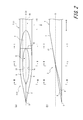
- FIG. 1 (a) is a top view
- FIG.1 (b) is a side view
- FIG.1 (c) is a bottom view
- FIG. 1 (d) is a perspective view.
- FIGS. 2A and 2B are enlarged views of a part of FIGS. 1A and 1B.
- 3A, 3B, and 3C are a cross-sectional view taken along the line II, the cross-sectional view taken along the line II-II, and the cross-sectional view taken along the line III-III, respectively.
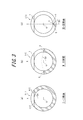
- FIG. 5A is a plan view of the upper surface side
- FIG. 5B is a sectional view taken along line IV-IV in FIG. 5A
- FIG. 5C is a sectional view taken along line VV in FIG.
- FIG. 5D is a sectional view taken along line VI-VI in FIG.
- 6A is a plan view of the upper surface side
- FIG. 6B is a sectional view taken along the line VII-VII in FIG. 6A
- FIG. 6C is a sectional view taken along the line VIII-VIII in FIG.
- FIG. 6D is a sectional view taken along line IX-IX in FIG.
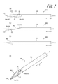
- FIGS. 7A, 7B, 7C, and 7D are a plan view, a side view, a plan view on the lower surface side, and a perspective view on the upper surface side.
- FIG. 14B is a cross-sectional view taken along the line XX in FIG. It is a top view of the upper surface side of the puncture needle as one embodiment of the present invention.
- FIG. 1 shows a puncture needle 1. Specifically, FIG. 1A is a plan view of the upper surface side of the puncture needle 1, FIG. 1B is a side view of the puncture needle 1, and FIG. FIG. FIG. 1 (d) is a perspective view of the puncture needle 1.
- the puncture needle 1 includes a main body portion 2 and a distal end portion 3, and defines a hollow portion 10 that communicates from the main body portion 2 to the distal end portion 3.
- the main body 2 is a tubular body that is continuous with the tip 3 and has a substantially circular cross-sectional outer shape.
- the “cross section” of the “cross sectional outline” referred to here means a cross section orthogonal to the central axis O of the main body 2.
- the tip 3 has a first blade surface 5 and a second blade surface 6 as blade surfaces configured by curved surfaces, and a blade surface configured by a plane. And an inclined surface (third blade surface) 7. Moreover, the 1st blade surface 5 and the 2nd blade surface 6 form the blade edge 9 which makes the needle tip 8 one end by the ridgeline which these cross
- the “needle tip” means the tip in the axial direction A of the central axis O of the main body 2 (hereinafter simply referred to as “central axial direction A”).
- the inclined surface 7 is continuous with the outer peripheral surface of the main body 2 on the side of the main body 2 in the central axis direction A, and the first blade surface 5 and the second blade surface 6 on the needle tip 8 side in the central axis direction A. And a plane inclined with respect to the central axis direction A.
- the first blade surface 5 and the second blade surface 6 are respectively continuous with the inclined surface 7 on the main body 2 side in the central axis direction A, and form a ridge line by crossing each other on the needle tip 8 side, that is, the blade edge 9 is formed. Forming. Further, the first blade surface 5 and the second blade surface 6 in the present embodiment define an opening 11 that is one end of the hollow portion 10 on the distal end portion 3 side.
- the angle of the second blade surface 6 in the cross section orthogonal to the central axis direction A varies depending on the position in the central axis direction A.
- the 2nd blade surface 6 can be visually recognized in the position where the blade edge 9 is formed. That is, the 2nd blade surface 6 is comprised by the curved surface extended so that it may twist toward the needle
- the first blade surface 5 is also formed of a curved surface extending so as to be twisted toward the needle tip 8 from a position continuous with the inclined surface 7 in the central axis direction A in the same manner as the second blade surface 6. Yes.
- the tip 3 is in a cross section orthogonal to the central axial direction A as it goes toward the needle tip 8 in the central axial direction A.
- a first blade surface 5 and a second blade surface 6 each having a curved surface with a gradually decreasing angle ⁇ with respect to the one virtual plane are provided (see FIG. 3 and the like). That is, the puncture needle 1 as the present embodiment is a puncture needle that can define such one virtual plane.
- the puncture needle 1 of the present embodiment has a plurality of planes that can be defined as the above-mentioned “virtual planes”. Therefore, here, for convenience of explanation, a plane X (hereinafter referred to as a plane X that includes the central axis O and is perpendicular to the inclined surface 7). (Referred to simply as “center plane X”) is defined as the “virtual plane”. However, for example, a plane including the blade edge 9 and the central axis O (in the present embodiment, the same plane as the central plane X) may be defined as the “virtual plane”. Further, it is only necessary to be able to define even one such virtual plane, and the present invention is not limited to a configuration in which a plurality of such virtual planes exist as in the present embodiment.
- the “tip portion” in the present application means one end portion of the puncture needle where the blade surface is formed
- the “main body portion” means a portion of the puncture needle where the blade surface is not formed.
- the distal end portion 3 in the present embodiment includes the first blade surface 5, the second blade surface 6, and the inclined surface (third blade surface) in the central axis direction A among the integral rod-like members constituting the puncture needle 1.
- ) 7 is formed.
- the main body 2 in the present embodiment includes a first blade surface 5, a second blade surface 6, and an inclined surface (third blade surface) in the central axis direction A among the integral rod-like members constituting the puncture needle 1.
- ) 7 is a portion having a substantially circular cross-sectional outer shape, in which 7 is not formed.
- a metal material such as stainless steel, aluminum or aluminum alloy, titanium or titanium alloy can be used.
- the main body 2 of the present embodiment is a tubular body in which the inner diameter of the inner peripheral surface and the outer diameter of the outer peripheral surface are uniform in the central axis direction A, and the end opposite to the tip 3 side in the central axis direction A
- the unit is connected to a medical instrument such as a syringe.
- the inner peripheral surface (the inner peripheral surface of the main body 2 and the inner peripheral surface of the distal end portion 3) of the rod-shaped member constituting the entire puncture needle 1 defines the hollow portion 10, and the inner periphery of the rod-shaped member.
- the inner diameter of the surface and the outer diameter of the outer peripheral surface are uniform in the central axis direction A, but are not limited to this configuration.
- the inner diameter of the inner circumferential surface of the rod-shaped member and the outer diameter of the outer circumferential surface of the rod-shaped member may be configured to gradually decrease toward the distal end portion 3 in the central axis direction A (see FIGS. 8 to 15).
- the outer diameter of the rod-shaped member may be a tapered shape that gradually decreases toward the distal end portion 3 in the central axis direction A, and the inner diameter of the rod-shaped member may be uniform in the central axis direction A.
- the inner diameter and the outer diameter of the rod-shaped member constituting the puncture needle 1 are provided in a part of the region in the central axis direction A, such as a portion where the inner diameter gradually decreases or gradually increases toward the distal end portion 3 in the central axis direction A.
- Various configurations can be adopted for the diameter depending on the use of the puncture needle 1 and the like.
- FIGS. 3A, 3B, and 3C are respectively a II sectional view, a II-II sectional view, and a III-III sectional view in FIG.
- the inclined surface 7 is a plane inclined with respect to the central axis direction A, and the main body 2 side of the inclined surface 7 is continuous with the outer peripheral surface of the main body 2.
- the needle tip 8 side of the inclined surface 7 is continuous with the first blade surface 5 and the second blade surface 6.
- the inclination angle of the inclined surface 7 with respect to the central axis direction A is larger than the inclination angle of the outer wall of the main body 2 with respect to the central axis direction A in the cross section including the central axis O.
- the outer diameter of the rod-shaped member constituting the puncture needle 1 is uniform in the central axis direction A, and the outer wall of the rod-shaped member is viewed in the central axis direction A when viewed in a cross section including the central axis O. Extends in parallel with. Therefore, if the inclined surface 7 is inclined with respect to the central axis direction A, the inclination angle of the inclined surface 7 is larger than the inclination angle of the outer wall of the main body 2.
- the rod-shaped member constituting the puncture needle 1 has a configuration in which the outer diameter gradually decreases or gradually increases toward the distal end portion 3 side in the central axis direction A, the inclined surface 7 is formed with respect to the central axis direction A.
- the main body 2 is configured to be inclined with respect to the outer wall of the cross section including the central axis O.
- the outer edge of the inclined surface 7 of the present embodiment on the side of the needle tip 8 in the central axis direction A is a direction B (hereinafter simply referred to as “orthogonal direction”) orthogonal to the central axis direction A, as shown in FIG. B ”). That is, the ridge line 12 formed at the continuous position of the inclined surface 7 and each of the first blade surface 5 and the second blade surface 6 extends in the orthogonal direction B.
- the ridge line 12 is located at a position adjacent to the opening 11 in the central axis direction A. That is, as shown in FIG. 2A, the position on the main body 2 side in the central axis direction A of the inner edge of the puncture needle 1 that defines the opening 11 is a part of the ridge line 12.
- the blade edge 9 of the present embodiment extends on the center plane X. Further, the needle tip 8 which is one end of the blade edge 9 is also located on the center plane X.
- FIG. 2A shows an II cross section, that is, a cross section orthogonal to the central axis direction A at a position where the first blade surface 5 and the second blade surface 6 and the inclined surface 7 are connected in the central axis direction A. Show. As shown in FIG.
- an angle ⁇ 1 with respect to the center plane X of each of the first blade surface 5 and the second blade surface 6 in the II section is 90 degrees.
- each of the first blade surface 5 and the second blade surface 6 extends linearly in a direction orthogonal to the central plane X (coincides with the ridgeline 12). .
- FIG. 3B shows a II-II cross section, that is, a cross section orthogonal to the central axis direction A at a position where the opening 11 is present in the central axis direction A.
- the angle ⁇ 2 with respect to the center plane X of each of the first blade surface 5 and the second blade surface 6 in the II-II cross section is an acute angle smaller than the angle ⁇ 1.
- FIG. 3C shows a III-III cross section, that is, a cross section orthogonal to the central axial direction A at the position where the blade edge 9 is formed in the central axial direction A.
- the angle ⁇ 3 with respect to the center plane X of each of the first blade surface 5 and the second blade surface 6 in the section III-III is an acute angle smaller than the angle ⁇ 1 and smaller than ⁇ 2. It is.
- the 1st blade surface 5 and the 2nd blade surface 6 are respectively straight in the cross sectional view orthogonal to the central axis direction A, and each of the 1st blade surface 5 and the 2nd blade surface 6 in this embodiment is.
- the angle ⁇ with respect to the central plane X in the cross section orthogonal to the central axis direction A gradually decreases toward the needle tip 8 side (closer to the needle tip 8) in the central axis direction A.
- 3A to 3C show the angles ⁇ 1 to ⁇ 3 of the second blade surface 6 with respect to the center plane X, respectively, the angle of the first blade surface 5 with respect to the center plane X is also the second blade surface 6. This is the same as the angles ⁇ 1 to ⁇ 3 of the surface 6.
- FIGS. 3A to 3C are used for illustrative purposes to show the magnitude relationship between the angles ⁇ 1, ⁇ 2, and ⁇ 3, and only the three cross sections described above are used. The magnitude relationship of the angle ⁇ is not established.
- the first blade surface 5 and the second blade surface 6 are connected to the inclined surface 7 and have a large step difference from the outer edge of the inclined surface 7 on the needle tip 8 side in the central axis direction A. It can be continued to the inclined surface 7 so as not to be formed (see FIG. 3A).
- the first blade surface 5 and the second blade surface 6 change the facing direction of the blade surface in the central axis direction A toward the needle tip 8 side from the position of the II cross section.
- the blade edge 9 can be formed so as to intersect each other at the position closer to the needle tip 8 than the opening 11 in the central axis direction A (see FIGS. 3B and 3C).
- the puncture needle 1 in this embodiment is provided with the 1st blade surface 5 and the 2nd blade surface 6 which have such a curved surface shape, the ridgeline 12 formed between the inclined surfaces 7 attaches the puncture needle 1 to a human body. It is possible to suppress the occurrence of puncture resistance when puncturing. Therefore, when the puncture needle 1 is punctured into the human body, it is possible to further reduce the pain felt by the punctured patient or the like.
- the amount of change in the angle ⁇ of each of the first blade surface 5 and the second blade surface 6 per unit length in the central axis direction A is constant.
- the inner edge 13 of the 1st blade surface 5 and the inner edge 14 of the 2nd blade surface 6 open the opening 11 of the end in the center axis direction A of the hollow part 10. As shown in FIG. It is partitioned. Although the opening 11 of this embodiment is divided only by the inner edge 13 of the 1st blade surface 5 and the inner edge 14 of the 2nd blade surface 6, it is not restricted to such a structure. For example, as shown in FIG.
- connection position of the first blade surface 50 and the second blade surface 60 and the inclined surface 70 is provided in a region where the opening 11 is located in the central axis direction A, that is, the first
- the connection position 120a of the first blade surface 50 and the inclined surface 70 and the connection position 120b of the second blade surface 60 and the inclined surface 70 are provided at positions sandwiching the opening 11 in the orthogonal direction B, and the first blade surface 50,
- the opening 11 may be defined by the respective edges of the second blade surface 60 and the inclined surface 70.
- the blade edge 9 is formed by a ridge line where the first blade surface 5 and the second blade surface 6 intersect.
- the blade edge 9 of the present embodiment extends on the central plane X, and the needle tip 8 that is one end of the blade edge 9 is also positioned on the central plane X. That is, the puncture needle 1 in this embodiment is a hollow needle having a symmetric configuration with respect to the central plane X.
- the blade edge 9 When the tip of the puncture needle 1 is sharpened and the blade edge 9 is provided as in this embodiment, when the puncture needle 1 is punctured into the human body, the blade edge 9 or the first blade surface near the blade edge 9 is used.
- the outer edge of 5 and the outer edge of the second blade surface 6 work to cut the skin, and the resistance applied to the skin at the time of puncture can be reduced. Therefore, it is possible to reduce pain felt by a patient or the like who is punctured with the puncture needle 1.
- the angle ⁇ (see FIG. 3) of the first blade surface 5 and the second blade surface 6 becomes smaller toward the needle tip 8 in the central axis direction A.
- the puncture needle 1 of the present embodiment can sharply configure the vicinity of the needle tip 8 as compared with the configuration in which the angle ⁇ is uniform in the region where the blade edge 9 extends in the central axis direction A, It becomes possible to further reduce the pain of the patient or the like when the puncture needle 1 is punctured.
- blade edge 9 and the needle tip 8 of the present embodiment are configured to be located on the center plane X, but a part or all of the blade edge 9 and the needle tip 8 are located on the center plane X. It can also be set as the structure which does not. Hereinafter, this configuration will be described as a second embodiment.
- the puncture needle 100 is different from the puncture needle 1 in the first embodiment in the configuration of the blade edge and the needle tip. Specifically, in the first embodiment, the entire blade edge 9 of the puncture needle 1 and the needle tip 8 are located on the center plane X, whereas in the present embodiment, the edge 90 of the puncture needle 100 is A part and the needle tip 80 are not located on the center plane X. In addition, the structure different from the puncture needle 1 of Embodiment 1 is mainly demonstrated here.
- FIG. 5 shows the puncture needle 100 in which a part of the blade edge 90 is not on the center plane X.
- FIG. 5 (a) is a plan view of the upper surface side of the puncture needle 100
- FIG. 5 (b) is a sectional view taken along the line IV-IV in FIG. 5 (a)
- FIG. FIG. 5D is a cross-sectional view taken along the line VV
- FIG. 5D is a cross-sectional view taken along the line VI-VI in FIG.
- the puncture needle 100 includes a main body portion 102 and a distal end portion 103, and defines a hollow portion 104 that communicates from the main body portion 102 to the distal end portion 103.
- the distal end portion 103 includes a first blade surface 51, a second blade surface 61, and an inclined surface 71.
- the 1st blade surface 51 and the 2nd blade surface 61 form the blade edge 90 which makes the needle point 80 one end by the ridgeline which these cross
- one end of the blade edge 90 on the main body 102 side is located on the center plane X, like the blade edge 9 in the puncture needle 1 of the first embodiment.
- the blade edge 90 is formed such that the distance from the center plane X gradually increases toward the needle tip 80 side in the center axis direction A.
- the blade edge 90 of the present embodiment is closer to the first blade surface 51 side in the orthogonal direction B from the center plane X as it goes to the needle tip 80 side in the center axis direction A (see FIG. 5A). It is a curved blade edge moving away from the upper side. Therefore, the needle tip 80 is not located on the center plane X.
- FIG. 5A it is a curved blade edge moving away from the upper side. Therefore, the needle tip 80 is not located on the center plane X.
- all the blade edges 90 are configured by curved curved blade edges.
- the present invention is not limited to this configuration, and all the blade edges 90 are formed by linear straight blade edges. It is also possible to configure. Moreover, it is good also as a blade edge which has a curved part only in a part of blade edge 90. FIG. Furthermore, it is good also as a blade edge which has a linear part only in a part of blade edge 90. FIG. Still further, one end of the blade edge 90 in the present embodiment on the main body 102 side in the central axis direction A is located on the central plane X, but the blade edge is formed so as not to intersect the central plane X at all. It is also possible.
- the blade edge 90 and the needle tip 80 As shown in FIG. 5A, when the puncture needle 100 is applied to the skin from the needle tip 80, the portion that contacts the skin is close to a line instead of a point. The force on the skin is dispersed. Therefore, if the configuration is such that the needle tip 80 is not located on the central plane X as in the puncture needle 100, it is compared with the configuration in which the needle tip 8 is located on the central plane X as in the puncture needle 1 of the first embodiment. Thus, sharp pain felt by the patient or the like when the sharp needle tip touches the skin can be reduced.
- the position and shape of the blade edge 90 and the position of the needle tip 80 in the puncture needle 100 shown in FIG. 5A are the same as the position and shape of the blade edge 9 of the puncture needle 1 according to the first embodiment, and the needle tip. 8B, the first blade surface 51 and the second blade surface 61 are different from the first blade surface 5 and the second blade surface 6 of the puncture needle 1, as shown in FIGS. Similarly, it is a curved surface that changes the inclination direction in the cross section perpendicular to the central axis direction A as it goes toward the needle tip 80 in the central axis direction A.
- FIG. 5B shows the IV-IV cross section, that is, the central axis direction A at the position where the first blade surface 51 and the second blade surface 61 and the inclined surface 71 are connected in the central axis direction A.
- the cross section orthogonal to is shown.
- the angle ⁇ 4 with respect to the center plane X of each of the first blade surface 51 and the second blade surface 61 in the IV-IV cross section is 90 degrees.
- each of the first blade surface 51 and the second blade surface 61 extends linearly in a direction orthogonal to the central plane X.
- FIG. 5C shows a VV cross section, that is, a cross section orthogonal to the central axis direction A in a region where the opening 111 is present in the central axis direction A.
- the angle ⁇ 5 with respect to the center plane X of each of the first blade surface 51 and the second blade surface 61 in the VV cross section is an acute angle smaller than the angle ⁇ 4.
- FIG. 5D shows a VI-VI cross section, that is, a cross section perpendicular to the central axis direction A at the position where the blade edge 90 is formed in the central axis direction A.
- the angle ⁇ 6 with respect to the center plane X of each of the first blade surface 51 and the second blade surface 61 in the VI-VI cross section is an acute angle smaller than the angle ⁇ 4 and smaller than ⁇ 5. It is.
- each of the first blade surface 51 and the second blade surface 61 with respect to the center plane X is configured to gradually decrease toward the needle tip 80 in the center axis direction A.
- the 1st blade surface 51 and the 2nd blade surface 61 are comprised by the helical surface which twists as it goes to the center axis direction A. As shown in FIG.
- the blade edge 90 of the puncture needle 100 does not extend on the center plane X. Therefore, depending on the extending direction of the blade edge 90, the first blade surface 51 or the second blade Although it can be considered that the angle ⁇ of the surface 61 does not gradually decrease toward the needle tip 80 side in the central axis direction A, both the angles ⁇ of the first blade surface 51 and the second blade surface 61 are the center. It does not become the structure which does not reduce gradually as it goes to the needle point 80 side of the axial direction A. That is, the angle ⁇ of at least one of the first blade surface 51 and the second blade surface 61 is configured to gradually decrease toward the needle tip 80 side in the central axis direction A.
- FIGS. 5B to 5D exemplarily show the angle ⁇ of the second blade surface 61 as ⁇ 4 to ⁇ 6, but the angle ⁇ of the first blade surface 51 is also shown in the central axis direction A. It is configured to gradually decrease toward the needle tip 80 side. Further, the three cross sections in FIGS. 5B to 5D are used for illustrative purposes in order to show the magnitude relationship between the angles ⁇ 4, ⁇ 5, and ⁇ 6. The magnitude relationship of the angle ⁇ is not established.
- the center plane X is set as one imaginary plane including the center axis O.
- the one including the center axis O is described.
- a plane including the central axis O and passing through the needle tip 80 can be set.
- the angle of at least one of the first blade surface 51 and the second blade surface 61 with respect to the plane including the central axis O and passing the needle tip 80 in the cross section orthogonal to the central axis direction A is the central axis line. In the direction A, it is configured to gradually decrease toward the needle tip 80 side.
- the puncture needle 200 is different from the puncture needle 100 of the second embodiment described above in that it is a solid needle that does not have a hollow portion.
- differences from the puncture needle 100 of the second embodiment will be mainly described.
- FIG. 6A is a plan view of the upper surface side of the puncture needle 200
- FIG. 6B is a cross-sectional view taken along the line VII-VII in FIG. 6A
- FIG. 6C is the view in FIG. VIII-VIII sectional view
- FIG. 6D shows a IX-IX sectional view of FIG. 6A.
- the puncture needle 200 of this embodiment includes a main body 202 and a tip 203.
- the puncture needle 200 is a solid needle that does not define a hollow portion that communicates from the main body portion 202 to the distal end portion 203.
- the distal end portion 203 includes a first blade surface 52, a second blade surface 62, and an inclined surface 72.
- the 1st blade surface 52 and the 2nd blade surface 62 form the blade edge 92 which makes the needle point 82 one end by the ridgeline which these cross
- the blade edge 92 of the present embodiment is formed by a ridge line that intersects the first blade surface 52 and the second blade surface 62 that extends from the outer edge on the needle tip 82 side in the central axis direction A of the inclined surface 72 to the needle tip 82. Is formed. Specifically, as illustrated in FIG. 6A, the blade edge 92 includes a straight line portion 204 located on the main body 202 side in the central axis direction A, and the straight line portion 204 continuously in the central axis direction A. A bending portion 205 located on the needle tip 82 side and having the needle tip 82 as one end. The straight line portion 204 extends on the central plane X.
- the curved portion 205 is curved such that the distance from the central axis central plane X (distance in the orthogonal direction B) gradually increases toward the needle tip 82 in the central axial direction A.
- the curved portion 205 of the present embodiment is closer to the first tip surface 52 side in the orthogonal direction B from the center plane X (upper side in FIG. 6A) as it goes toward the needle tip 82 in the central axis direction A. It extends so as to go away. Therefore, the needle tip 82 is not located on the center plane X, like the puncture needle 100 of the second embodiment described above.
- the blade edge 92 is configured by the straight portion 204 and the curved portion 205.
- the present invention is not limited to this, and the entire blade edge 92 is linear. It is possible to use a configured straight blade edge or a curved blade edge in which all the blade edges 92 are formed in a curved shape. It is also possible to reverse the positions of the straight line portion 204 and the curved portion 205 in the central axis direction A.
- the straight line part 204 in the blade edge 92 of this embodiment is the structure extended on the center plane X, all of the straight line parts 204 are not on the center plane X, or only a part of straight line part 204 is. A configuration on the central plane X is also possible.
- the patient or the like feels sharp when the sharp needle tip touches the skin, like the puncture needle 100 of the second embodiment described above. Pain can be reduced.
- the angle ⁇ of the first blade surface 52 and the second blade surface 62 with respect to the center plane X in the cross section orthogonal to the central axis direction A will be described.
- the angle ⁇ of the first blade surface 52 and the second blade surface 62 gradually decreases toward the needle tip 82 side in the central axis direction A.
- it is comprised by the curved surface which changes an inclination direction.
- FIG. 6B is a cross-sectional view taken along the line VII-VII, that is, in the central axis direction A at the position where the first blade surface 52 and the second blade surface 62 and the inclined surface 72 are connected in the central axis direction A.
- the cross section orthogonal to is shown.
- the angle ⁇ 7 with respect to the center plane X of each of the first blade surface 52 and the second blade surface 62 in the section VII-VII is 90 degrees.
- Each of the surface 52 and the second blade surface 62 extends linearly in a direction orthogonal to the central plane X.
- FIG. 6C shows a VIII-VIII cross section. As shown in FIG. 6C, the angle ⁇ 8 with respect to the center plane X of each of the first blade surface 52 and the second blade surface 62 in the section VIII-VIII is an acute angle smaller than the angle ⁇ 7.
- FIG. 6 (d) shows a IX-IX cross section.
- the angle ⁇ 9 with respect to the center plane X of each of the first blade surface 52 and the second blade surface 62 in the IX-IX cross section is smaller than the angle ⁇ 7 and smaller than ⁇ 8. It is.
- each of the first blade surface 52 and the second blade surface 62 with respect to the center plane X is configured to gradually decrease toward the needle tip 82 in the center axis direction A.
- the 1st blade surface 52 and the 2nd blade surface 62 are comprised by the helical surface which twists as it goes to the central axis direction A. As shown in FIG.
- the angle ⁇ of the second blade surface 62 is shown as ⁇ 7 to ⁇ 9, but the angle ⁇ of the first blade surface 52 is also related to the central axis direction A. It is configured to gradually decrease toward the needle tip 82 side.
- the angle ⁇ of both the first blade surface 52 and the second blade surface 62 is not limited to the configuration in which the angle ⁇ gradually decreases toward the needle tip 82 side in the central axis direction A, and the first blade surface 52 and the second blade surface 62 Of these, the angle ⁇ of at least one of the blade surfaces may be configured to gradually decrease toward the needle tip 82 side in the central axis direction A.
- the center plane X is set and described as one virtual plane including the center axis O, but one including the center axis O is described. Other planes such as a plane including the central axis O and passing through the needle tip 82 can be set as the virtual plane.
- the puncture needle 300 is different from the puncture needle 1 in that the puncture needle 1 according to the first embodiment includes the inclined surface 7 but does not include a surface corresponding to the inclined surface 7.
- differences between the puncture needle 300 according to the present embodiment and the puncture needle 1 according to the first embodiment will be mainly described, and description of configurations common to both will be omitted.
- FIG. 7 is a view showing the puncture needle 300 of the present embodiment. Specifically, FIGS. 7A, 7 ⁇ / b> B, 7 ⁇ / b> C, and 7 ⁇ / b> D respectively show a top view, a side view, a bottom view, and a perspective view of the puncture needle 300.
- the puncture needle 300 includes a main body portion 302 and a distal end portion 303, and defines a hollow portion 304 that communicates from the main body portion 302 to the distal end portion 303.
- the distal end portion 303 includes a first blade surface 53 and a second blade surface 63.
- the 1st blade surface 53 and the 2nd blade surface 63 form the blade edge 93 which makes the needle point 83 an end by the ridgeline which these cross
- the blade surface of the puncture needle 300 is composed of a first blade surface 53 and a second blade surface 63, and a third blade corresponding to the inclined surface 7 of the puncture needle 1 of the first embodiment described above. Does not have a surface. Therefore, the blade edge 93 in the present embodiment is positioned on the main body 302 side with respect to the opening 311 in the same direction A and the first blade edge 93a positioned on the blade edge 83 side with respect to the opening 311 in the central axis direction A. A second blade edge 93b.
- the first blade edge 93a is a ridge line intersecting the end of the first blade surface 53 and the second blade edge 63 on the needle tip 83 side in the central axis direction A
- the second blade edge 93b is It is a ridgeline where the end portions of the first blade surface 53 and the second blade edge 63 on the main body portion 302 side in the central axis direction A intersect.
- first blade edge 93a is the same as the blade edge 9 in the first embodiment, the description thereof is omitted here.
- the second blade edge 93b is a straight ridge line extending on the central plane X, like the first blade edge 93a, and is located on an extension line of the first blade edge 93a.
- the second blade edge 93b functions to cut through the skin in the same manner as the first blade edge 93a when the puncture needle 300 is punctured into the human body. That is, by providing the second blade edge 93b, when puncturing the puncture needle 300 into the human body, among the edges that define the opening 311, the edge that is located on the main body 302 side in the central axis direction A, An increase in puncture resistance can be suppressed. Therefore, the pain felt by the patient or the like who is punctured with the puncture needle 300 can be reduced.
- the second blade surface 63 has a larger visible range as it goes toward the needle tip 83 in the central axis direction A. That is, the second blade surface 63 is a spiral surface that changes its surface shape so as to be twisted toward the needle tip 83 side in the central axis direction A. Although only the second blade surface 63 is visible in FIG. 7B, the surface shape of the first blade surface 53 also changes so as to be twisted toward the needle tip 83 side in the central axis direction A. It is a spiral surface.
- the puncture needle 300 of the present embodiment does not include a surface corresponding to the inclined surface 7 of the first embodiment, the above-described central plane X cannot be defined as one virtual plane. Therefore, in this embodiment, for convenience of explanation, the plane Y including the first blade edge 93a and the central axis O is set as one virtual plane.
- angles of the first blade surface 53 and the second blade surface 63 in the cross section perpendicular to the central axis direction A with respect to the plane Y are gradually reduced as they approach the needle tip 83 side in the central axis direction A. It is configured.
- the puncture needle according to the present invention can be realized by various specific configurations, and is not limited to the configurations described in the first to fourth embodiments. So far, for ease of explanation, the puncture needles 100, 200, and 300 according to the second, third, and fourth embodiments have mainly been described with respect to differences from any of the above-described embodiments. It is of course possible to construct another puncture needle by combining various configurations described in 1-4. For example, in Embodiment 2, although the structure provided with the three blade surfaces of the 1st blade surface 51, the 2nd blade surface 61, and the inclined surface 71 was shown, for example like Embodiment 4, a 1st blade surface and It is also possible to have a configuration with only two blade surfaces, the second blade surface.
- the inclined surface 71 of the second embodiment is connected to the connection position of the first blade surface 51 and the inclined surface 71 and the connection position of the second blade surface 61 and the inclined surface 71.
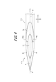
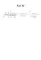
- FIG. 15 shows a plan view of the upper surface side of the puncture needle 1 ′.
- the puncture needle 1 ′ for explaining the manufacturing method here is an embodiment of the present invention, and compared with the puncture needle 1 explained as the first embodiment described above, the puncture needle 1 ′ is outside the bar-like member constituting the puncture needle 1 ′.
- the configuration is different in that the diameter gradually decreases toward the tip.
- the puncture needle 1 'and the puncture needle 1 as the first embodiment are the same except for this difference, and thus the description thereof is omitted here.
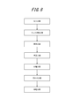
- FIG. 8 is a process diagram showing a manufacturing process of the puncture needle 1 ′.
- the manufacturing method of the puncture needle 1 ′ includes a receiving step of receiving a strip-shaped metal plate material into a press molding machine, and press-molding the plate material continuously by this press molding machine.
- a press forming step for obtaining a tube body 15a as a plurality of rod-like members 15 partially connected to each other (see FIGS. 9 to 12), and a joining step for bonding a joint portion of the tube body 15a by welding or an adhesive At least one of a straightening step of correcting the shape of the tube body 15a so that the central axis of the tube body is substantially straight, a separation step of separating the tube body 15a from the plate material (see FIG. 13), and the tube body 15a.
- a blade surface forming step (see FIG. 14) for forming the puncture body 1 by forming a blade surface by wire electric discharge machining (wire cut) at the end of the piercing body, and a polishing step for polishing the puncture body 1 by ion etching processing, have.
- the strip-shaped metal plate is received by a press molding machine (not shown).
- the plate member is moved along the longitudinal direction with respect to the press molding machine by the moving mechanism, and the molding portion of the plate material is positioned at the molding position of the press molding machine. That is, first, a portion of a plate material where a later-described developed shape body is punched is placed at a position of a later-described punching portion that punches the developed shape body of the press molding machine.
- plate material metal materials, such as stainless steel, aluminum, an aluminum alloy, titanium, or a titanium alloy, are mentioned similarly to the material of the puncture needle 1 mentioned above, for example.
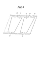
- the press forming process includes a first process of punching out a developed shape body in which a tubular body 15a is developed from a plate material with a press molding machine in a state where a part of the developed shape body is connected to the plate material, and this expanded shape body by a press molding machine. Is bent at least once using a convex mold and a concave mold, and formed into a tubular shape, thereby obtaining a tubular body 15a partially connected to the plate material. As shown in FIG. 12, in this embodiment, the inner diameter and the outer diameter of the tube body 15a are maximum at one end and minimum at the other end, and gradually decrease from the one end toward the other end.
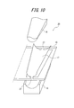
- a punched portion is formed by mechanically punching from a plate material 16 a developed shape body 17 having a shape in which a tubular body 15a is developed, with a part thereof being connected to the plate material 16.
- a first bent portion 20 that bends the unfolded shape body 17 punched by the punched portion using a concave mold (mold) 18 and a convex mold (mold) 19, and the first bent section 20.
- the second bent portion 23 that is further bent using the concave mold (mold) 21 and the convex mold (mold) 22 is bent by the second bent portion 23.
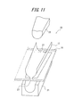
- the developed expanded body 17 is further curved using a pair of concave dies (metal molds) 24 and 25 having a shape corresponding to the outer shape of the tubular body 15a, and has a third bent portion 26 which is formed into a tubular shape.
- a press molding machine is used.
- connection part 27 which connects the edge part with the larger diameter of the pipe body 15a to the board
- the portion may be moved downward by a predetermined amount in the drawing so that the central axis of the tube body 15a and the surface of the plate member 16 become substantially parallel.
- the connecting portion 27 that connects the end portion having the smaller diameter of the tubular body 15a to the plate member 16 is deformed inward in the figure, so that the end portion having the smaller diameter of the tubular body 15a is located on the upper side in the figure.
- the tube body 15a moves by a predetermined amount, and the end of the tube body 15a having the larger diameter moves downward by a predetermined amount in the figure, whereby the central axis of the tube body 15a and the surface of the plate member 16 become substantially parallel.
- the third bent portion 26 is located between the concave mold 24 and the concave mold 25, and a core (mold) having a shape corresponding to the inner shape of the tubular body 15a.
- the core may be disposed so as to be positioned in the hollow portion of the tube body 15a, and the developed shape body 17 may be pressed and bent to be formed into a tubular shape.
- a mechanical punching method is used as a method of punching the developed shape body 17 from the plate material 16, but the present invention is not limited to this, and a punching method using a laser or the like may be employed.
- the joints 28 (see FIG. 12) of the pipes 15a are joined by welding or an adhesive.
- the part of the joint 28 of the tubular body 15a is joined in a liquid-tight and firm manner.
- welding and bonding with an adhesive are preferable because the tube body 15a is made of metal and the outer diameter of the tube body 15a is relatively small.
- welding can be used for welding.
- laser welding such as carbon dioxide laser welding, YAG laser welding, and excimer laser welding is preferable, and among these, they are inexpensive and fine.
- Carbon dioxide laser welding or YAG laser welding suitable for processing is particularly preferred.
- each tube body 15a is corrected so that the central axis of each tube body 15a becomes a substantially straight line.
- a pair of rollers that are spaced apart from each other by a predetermined distance is used, and the tube body 15a is disposed between the pair of rollers and passed therethrough. Thereby, the tube body 15a is restrained and corrected between the rollers so that the central axis thereof is substantially a straight line.
- each tube body 15a is sequentially separated from the plate material 16.
- the tubular body 15a is separated at the boundary between the tubular body 15a and the pair of connecting portions 27.
- the method for separating the tube body 15a from the plate member 16 is not particularly limited, and may be mechanically cut or separated using a laser or the like.
- each tubular body 15a is temporarily fixed substantially simultaneously with the separation of the tubular body 15a or after the tubular body 15a is separated, and the positional relationship between the tubular bodies 15a is maintained.
- the temporary fixing is performed by sticking both ends of the tube body 15a to a pair of adhesive tapes (temporary fixing members) 29 as shown in FIG. 13 (the central portion in the longitudinal direction of the tube body 15a). At least one place except for is attached to the adhesive tape 29).
- the interval between the temporarily fixed adjacent tube bodies 15a is not particularly limited (there may be no interval), and is appropriately set according to various conditions. However, the adjacent tubes partially connected to the plate 16 are used. It is preferable to set it smaller than the interval between the bodies 15a. Thereby, each tubular body 15a can be densely arranged, and in the next step (blade surface forming step), blade surfaces can be formed simultaneously on a large number of tubular bodies 15a, thereby improving productivity. Can be improved.
- the interval between the adjacent tubular bodies 15a in the temporary fixing can be arbitrarily adjusted by adjusting the movement amount (feed pitch) of the adhesive tape 29.
- the previous tube body 15 a is attached to the adhesive tape 29.
- the amount of movement of the adhesive tape 29 until the next tube body 15a is attached to the adhesive tape 29 after the attachment is defined as the pitch of the adjacent tube bodies 15a partially connected to the plate 16 (the previous tube body). It is set smaller than the amount of movement of the plate material 16 after the separation of 15a until the next tube body 15a is separated.
- the puncture needle 1 ′ is formed by forming a blade surface on at least one end of each tubular body 15 a as the linear member 15 and forming a needle tip.
- a blade surface is simultaneously formed for each tubular body 15a while maintaining the positional relationship between the tubular bodies 15a.
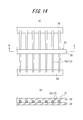
- each tubular body 15a is held at a substantially central portion in the longitudinal direction, and the positional relationship between the tubular bodies 15a is maintained. That is, as shown in FIG. 14, a holding mechanism 31 having a pair of elongated gripping portions (holding portions) 30 that grip (hold) substantially the center portion of each tubular body 15a is attached to a pair of adhesive tapes 29. The positional relationship between the tube bodies 15a attached and temporarily fixed is maintained as it is. And the 1st blade surface 5 ', 2nd blade surface 6', and the inclined surface in the site
- each tubular body 15a (Third blade surface) A tip 3 'having 7' is formed (see FIG. 15).
- each adhesive tape 29 is removed from the puncture needle 1 'formed with the distal end portion 3'.
- the inclined surface 7 ' is formed by wire cutting. Specifically, the tubular body 15a as the linear member 15 having a substantially circular outer cross section is moved in one direction inclined with respect to the wire by a predetermined angle with respect to the central axis direction A (see FIG. 15). Thus, the inclined surface 7 'is formed.
- the predetermined angle here is determined by the angle of the inclined surface 7 'with respect to the central axis direction A.
- the linear member 15 is rotated in one direction around the central axis O (see FIG. 15) of the linear member 15 and moved when the inclined surface 7 ′ is formed.
- the first blade surface 5 ′ is formed at one end of the linear member 15 by wire cutting while moving in one direction inclined at a predetermined angle with respect to the central axis direction A, which is the same direction as the first direction.
- the linear member 15 when forming the inclined surface 7 ′, the linear member 15 is not rotated about the central axis O but is simply moved at a predetermined constant speed in one direction inclined by a predetermined angle with respect to the central axis direction A. .
- the center axis O is the center.
- the first blade surface 5 ′ is formed following the inclined surface 7 ′.
- the first blade surface 5 ′ is formed by rotating the rod-like member 15 counterclockwise. The rod-shaped member 15 is rotated at a predetermined constant rotational speed.
- the inclined surface 7 ′ and the first blade surface 5 ′ can be formed by a single wire cutting process.
- the linear member 15 is rotated in the reverse direction (clockwise direction in the present embodiment) around the central axis O, and the one direction described above is inclined at a predetermined angle with respect to the central axis direction A.
- the second blade surface 6 ′ is formed at a position different from the first blade surface 5 ′ in one end by wire cutting while moving in the opposite direction of this one direction.
- the second blade surface 6 ' is formed, and the blade edge 9' having the needle tip 8 'formed by the ridge line intersecting the first blade surface 5' and the second blade surface 6 'is formed.
- the movement of the linear member 15 in one direction inclined by a predetermined angle with respect to the central axis direction A or in the opposite direction of the one direction is performed at a speed equal to the speed at which the first blade surface 5 ′ is formed. Do. Further, the rotation of the linear member 15 around the central axis O is performed at a speed equal to the rotational speed when the first blade surface 5 ′ is formed.
- the second blade surface 6 ′ is formed as the second wire cutting process.
- the first and first blade edges 9 ′ formed by ridge lines intersecting the first blade surface 5 ′ and the second blade surface 6 ′ are simultaneously formed. Since the entire blade surface of the tip 3 'of the puncture needle 1' can be formed by two cuts of the two-wire cutting process, the time required for the blade surface forming step of the tip 3 'can be shortened. .
- the second wire cutting process for forming the second blade surface 6 ' can be executed by one of the following two methods.
- the first method is a method of forming the second blade surface 6 ′ from the blade edge 8 ′ side toward the inclined surface 7 ′ side
- the second method is the method of forming the second blade surface 6 ′ on the inclined surface 7. This is a method of forming from the ′ side toward the blade edge 8 ′ side.
- the linear member 15 is rotated clockwise around the central axis O and inclined at a predetermined angle with respect to the central axial direction A.
- the second blade surface 6 ' is formed by moving in the direction opposite to the one direction described above.
- the linear member 15 is rotated clockwise around the central axis O and inclined at a predetermined angle with respect to the central axial direction A.
- the second blade surface 6 ' is formed by moving in the same direction as the one direction described above. Note that the first method is more efficient than the second method because the second wire cut processing can be executed after the first wire cut processing.
- this embodiment demonstrated the method of moving the pipe 15a as the linear member 15 with respect to a wire for wire cut processing
- the method of moving a wire with respect to the linear member 15 is demonstrated. May be adopted. However, it is more preferable to move the linear member 15 and perform wire cutting because the work is easy.
- the puncture needle 1 ′ including the tip portion 3 ′ on which the first blade surface 5 ′, the second blade surface 6 ′, and the inclined surface 7 ′ are formed is polished.
- the puncture needle 1 ′ is subjected to ion etching using argon as a medium in a vacuum atmosphere using a plasma ion gas.
- burrs generated during wire electric discharge machining can be dissolved and vaporized, and the first blade surface 5 ′, the second blade surface 6 ′, the inclined surface 7 ′, the needle tip 8 ′, and the desired shape can be formed.
- the puncture needle 1 'having the tip 3' on which the blade edge 9 'is formed can be polished relatively easily and reliably.
- the puncture needle 1 ′ can be manufactured by the above process. Although the manufacturing method of puncture needle 1 'was demonstrated in this embodiment, the puncture needle 1 as Embodiment 1 can also be manufactured with the same manufacturing method.
- the puncture needles 100 and 300 as the second and fourth embodiments can also be manufactured by using the same method.
- the needle tips 80 and 82 are configured not to be located on the center plane X, in the above-described blade surface forming step, the moving speed and the rotational speed of the tubular body 15a when forming the first blade surface are:
- the asymmetrical blade surface may be formed by making it different from the moving speed and rotational speed of the tube body 15a when forming the second blade surface.
- the puncture needle 200 as the third embodiment is a solid needle, the above-described receiving process, press molding process (see FIGS. 9 to 12), joining process, correction process, separation process (see FIG. 13). Is not necessary. Therefore, the puncture needle 200 can be manufactured by performing the above-described blade surface forming process (see FIG. 14) and the polishing process on the solid rod-shaped member 15.
- the present invention relates to a medical puncture needle and a method for manufacturing the puncture needle.
Landscapes
- Health & Medical Sciences (AREA)
- Engineering & Computer Science (AREA)
- Hematology (AREA)
- Anesthesiology (AREA)
- Biomedical Technology (AREA)
- Heart & Thoracic Surgery (AREA)
- Vascular Medicine (AREA)
- Life Sciences & Earth Sciences (AREA)
- Animal Behavior & Ethology (AREA)
- General Health & Medical Sciences (AREA)
- Public Health (AREA)
- Veterinary Medicine (AREA)
- Mechanical Engineering (AREA)
- Infusion, Injection, And Reservoir Apparatuses (AREA)
- Electrical Discharge Machining, Electrochemical Machining, And Combined Machining (AREA)
Abstract
Description
まず、本発明に係る医療用の穿刺針の一実施形態としての穿刺針1について説明する。図1は、穿刺針1を示す図である。具体的に、図1(a)は、穿刺針1の上面側の平面図、図1(b)は、穿刺針1の側面図、図1(c)は、穿刺針1の下面側の平面図を示すものである。図1(d)は、穿刺針1の斜視図である。
本実施形態の本体部2は、中心軸線方向Aにおいて、内周面の内径及び外周面の外径が一様な管体であり、中心軸線方向Aにおける先端部3側とは反対側の端部は、例えばシリンジなどの医療用器具に接続される。
図2(a)、(b)は、それぞれ図1(a)、(b)の先端部3についての拡大図である。図3(a)、(b)、(c)は、それぞれ図2におけるI-I断面図、II-II断面図、III-III断面図を示す。
図2(a)に示すように、第1刃面5及び第2刃面6のそれぞれは、中心軸線方向Aにおける本体部2側で、傾斜面7と連続している。より具体的に、第1刃面5及び第2刃面6は、中心平面Xを挟む両側でそれぞれ傾斜面7と連続している。図3(a)はI-I断面、すなわち、中心軸線方向Aにおいて第1刃面5及び第2刃面6と傾斜面7とが接続する位置での、中心軸線方向Aと直交する断面を示す。図3(a)に示すように、I-I断面での第1刃面5及び第2刃面6それぞれの、中心平面Xに対する角度θ1は、90度である。換言すれば、I-I断面において、第1刃面5及び第2刃面6のそれぞれは、中心平面Xと直交する方向に直線状に延在している(稜線12と一致している)。
刃縁9は、上述したように、第1刃面5及び第2刃面6が交差する稜線により形成される。また、本実施形態の刃縁9は、上述したように、中心平面X上に延在し、刃縁9の一端である針先8についても、中心平面X上に位置する。つまり、本実施形態における穿刺針1は、中心平面Xについて対称な構成を有する中空針である。
次に、本発明の一実施形態としての穿刺針100について説明する。穿刺針100は、実施形態1における穿刺針1と比較して、刃縁及び針先の構成が相違する。具体的に、実施形態1では、穿刺針1の刃縁9の全部及び針先8が中心平面X上に位置しているのに対して、本実施形態では、穿刺針100の刃縁90の一部及び針先80が、中心平面X上に位置しない。なお、ここでは実施形態1の穿刺針1と相違する構成について主に説明する。
次に、本発明の一実施形態としての穿刺針200について説明する。穿刺針200は、上述した実施形態2の穿刺針100と比較して、中空部を有さない中実針である点で相違している。ここでは、実施形態2の穿刺針100との相違点について主に説明する。
次に、本発明の一実施形態としての穿刺針300について説明する。穿刺針300は、実施形態1の穿刺針1が傾斜面7を備える構成であるのに対して、傾斜面7に相当する面を備えない点で、穿刺針1と相違している。ここでは、本実施形態としての穿刺針300と、実施形態1の穿刺針1との相違点について主に説明し、両者で共通する構成に関しては説明を省略する。
最後に、本発明の一実施形態として、穿刺針1´を製造する製造方法について説明する。図15は、穿刺針1´の上面側の平面図を示す。ここで製造方法を説明する穿刺針1´は、本発明の一実施形態であって、上述の実施形態1として説明した穿刺針1と比較して、穿刺針1´を構成する棒状部材の外径が、先端部側に向かうにつれて漸減する構成である点で構成上相違する。穿刺針1´と、実施形態1としての穿刺針1とは、この相違点以外は同様であるため、ここでは説明を省略する。なお、図15では、実施形態1の穿刺針1と共通する部位に、図1(a)と共通の付番と、記号“´”(ダッシュ)とを併せて付している。以下、穿刺針1´を製造する製造方法について詳細に説明する。図8は、穿刺針1´の製造工程を示す工程図である。
帯状をなす金属製の板材を図示しないプレス成形機に受け入れる。この場合、移動機構により、プレス成形機に対して板材をその長手方向に沿って移動させ、板材の成形箇所をプレス成形機の成形位置に位置させる。すなわち、まずは、板材のうち後述する展開形状体が打ち抜かれる部位を、プレス成形機の展開形状体の打ち抜きを行う後述する打ち抜き部の位置に配置させる。なお、板材の材料としては、上述した穿刺針1の材料と同様に、例えば、ステンレス鋼、アルミニウムまたはアルミニウム合金、チタンまたはチタン合金等の金属材料が挙げられる。
プレス成形工程は、プレス成形機により、板材から、管体15aを展開した形状をなす展開形状体を板材に一部が繋がった状態で打ち抜く第1工程と、プレス成形機により、この展開形状体を少なくとも1回、凸型と凹型とを用いて湾曲させ、管状に成形して、板材に一部が繋がった状態の管体15aを得る第2工程とを有している。図12に示すように、この管体15aは、本実施形態では、内径及び外径が、その一端において最大、他端において最小であり、この一端から他端に向かって漸減している。
接合工程では、各管体15aの継ぎ目28の部分(図12参照)を溶接又は接着剤により接合する。これにより、管体15aの継ぎ目28の部分が液密かつ強固に接合される。この場合、溶接と接着剤による接着とでは、管体15aが金属製であることと、管体15aの外径が比較的小さいこととから、溶接が好ましい。そして、溶接の際は、母材を含めた接合部(継ぎ目28の部分)を溶融して溶接することが好ましい。
矯正加工では、各管体15aの中心軸線が略直線になるように各管体15aの形状を矯正する。この場合、例えば、所定距離離間して配置された一対のローラを用い、管体15aをその一対のローラの間に配置して通過させる。これにより、管体15aは、その中心軸が略直線になるようにローラ間で抑え付けられ、矯正される。なお、本実施形態とは異なる方法により矯正工程を実行してもよい。
分離工程では、板材16から各管体15aを順次分離する。この場合、管体15aは、その管体15aと一対の接続部27との境界部において分離される。板材16から管体15aを分離する方法は、特に限定されるものではなく、例えば、機械的に切断しても、レーザー等を用いて切り離してもよい。また、分離工程では、管体15aの分離と略同時または管体15aの分離後に、各管体15aを仮固定し、管体15a同士の位置関係を保持する。この仮固定は、本実施形態では、図13に示すように、管体15aの両端部を一対の粘着テープ(仮固定部材)29に貼り付けることで行う(管体15aの長手方向の中央部を除く少なくとも1箇所を粘着テープ29に貼り付けることにより行う)。
刃面形成工程では、線状部材15としての各管体15aの少なくとも一方の端部に刃面を形成して、針先を形成することによって、穿刺針1´を形成する。この場合、管体15a同士の位置関係を保持した状態で、各管体15aに対して同時に刃面を形成する。このように、管体15a同士の位置関係を保持した状態で刃面を形成するので、容易、確実かつ正確に、刃面を形成することができ、また、各管体15aに対して同時に刃面を形成するので、生産性を向上させることができる。
研磨工程では、第1刃面5´、第2刃面6´、及び傾斜面7´が形成された先端部3´を備える穿刺針1´を研磨する。研磨方法としては、穿刺針1´を、真空雰囲気下でプラズマイオンガスを用いて、アルゴンを媒体としてイオンエッチング加工を行う。かかる研磨方法によれば、ワイヤー放電加工時に生じるバリを溶解気化することができ、所望の形状の第1刃面5´、第2刃面6´、傾斜面7´、針先8´、及び刃縁9´が形成された先端部3´を備える穿刺針1´を、比較的に容易かつ確実に研磨することができる。
2、102、202、302:本体部
3、3´、103、203、303:先端部
5、5´、50、51、52、53:第1刃面(刃面)
6、6´、60、61、62、63:第2刃面(刃面)
7、7´、70、71、72、73:傾斜面(刃面)
8、8´、80、82、83:針先
9、9´、90、92、93:刃縁
10、104、304:中空部
11、11´、111、311:開口
12、12´:稜線
120a、120b:接続位置
13:第1刃面の内縁
14:第2刃面の内縁
15:棒状部材
15a:管体
16:板材
17:展開形状体
18:第1の曲げ部の凹型(金型)
19:第1の曲げ部の凸型(金型)
20:第1の曲げ部
21:第2の曲げ部の凹型(金型)
22:第2の曲げ部の凸型(金型)
23:第2の曲げ部
24、25:第3の曲げ部の一対の凹型(金型)
26:第3の曲げ部
27:接続部
28:継ぎ目
29:粘着テープ(仮固定部材)
30:把持部(保持部)
31:保持機構
204:直線部
205:湾曲部
A:中心軸線方向
B:中心軸線方向と直交する方向(直交方向)
O:中心軸線
X:傾斜面に垂直で中心軸線を含む平面(中心平面)
Y:第1刃縁及び中心軸線を含む平面
θ:中心軸線方向と直交する断面における中心平面に対する角度
θ1~θ9:中心軸線方向と直交する断面における第2刃面の中心平面に対する角度
Claims (8)
- 針先を含む先端部と、当該先端部と連続し、略円形状の断面外形を有する本体部と、を備え、
前記本体部の中心軸線を含む1つの仮想平面を設定した場合に、前記先端部は、前記中心軸線方向において前記針先側に向かうにつれて、前記中心軸線方向に直交する断面における前記仮想平面に対する角度が漸減する、曲面で構成された刃面を備えることを特徴とする医療用の穿刺針。 - 前記刃面は、交差する稜線により、前記針先を一端とする刃縁を形成する曲面状の第1刃面及び第2刃面を備え、
前記中心軸線方向において前記針先側に向かうにつれて、前記第1刃面及び前記第2刃面のうち少なくとも一方の刃面の、前記中心軸線に直交する断面における前記仮想平面に対する角度が漸減することを特徴とする請求項1に記載の穿刺針。 - 前記先端部は、前記第1刃面及び前記第2刃面と連続すると共に、前記中心軸線に対して傾斜する平面で構成される傾斜面を備え、
前記仮想平面は、前記傾斜面に垂直で前記中心軸線を含む平面であることを特徴とする請求項2に記載の穿刺針。 - 前記針先は、前記傾斜面に垂直で前記中心軸線を含む前記平面上に位置しないことを特徴とする請求項3に記載の穿刺針。
- 前記本体部から前記先端部まで連通する中空部を区画しており、
前記先端部において、前記第1刃面の内縁及び前記第2刃面の内縁は、前記中空部の前記中心軸線方向における一端の開口を区画していることを特徴とする請求項2乃至4のいずれか1つに記載の穿刺針。 - 前記中心軸線方向における単位長さ当りの前記角度の角度変化量は、一定であることを特徴とする請求項1乃至5のいずれか1つに記載の穿刺針。
- 横断面の外形が略円形状の線状部材を、当該線状部材の中心軸線を中心に一方向に回転させると共に当該中心軸線方向に対して所定角度だけ傾斜する一方向に移動させながら、ワイヤーカットによって、前記線状部材の一端部に刃面を形成することを特徴とする医療用の穿刺針の製造方法。
- 前記刃面を第1刃面とした場合に、前記線状部材を、前記中心軸線を中心に前記一方向とは逆方向に回転させると共に前記中心軸線方向に対して前記所定角度傾斜した前記一方向又は当該一方向の逆方向に移動させながら、ワイヤーカットによって、前記一端部のうち前記第1刃面とは異なる位置に第2刃面、及び、前記第1刃面と前記第2刃面とが交差する稜線で構成される、針先を有する刃縁、を形成することを特徴とする、請求項7に記載の穿刺針の製造方法。
Priority Applications (5)
| Application Number | Priority Date | Filing Date | Title |
|---|---|---|---|
| CN201480074402.4A CN105939740B (zh) | 2014-01-31 | 2014-11-19 | 医疗用的穿刺针以及穿刺针的制造方法 |
| EP14880929.6A EP3100752B1 (en) | 2014-01-31 | 2014-11-19 | Puncture needle for medical use, and method for manufacturing puncture needle |
| JP2015559625A JP6576250B2 (ja) | 2014-01-31 | 2014-11-19 | 医療用の穿刺針及び穿刺針の製造方法 |
| US15/205,896 US10201665B2 (en) | 2014-01-31 | 2016-07-08 | Medical puncture needle and method of manufacturing puncture needle |
| US16/234,373 US10926041B2 (en) | 2014-01-31 | 2018-12-27 | Medical puncture needle and method of manufacturing puncture needle |
Applications Claiming Priority (2)
| Application Number | Priority Date | Filing Date | Title |
|---|---|---|---|
| JP2014017828 | 2014-01-31 | ||
| JP2014-017828 | 2014-01-31 |
Related Child Applications (1)
| Application Number | Title | Priority Date | Filing Date |
|---|---|---|---|
| US15/205,896 Continuation US10201665B2 (en) | 2014-01-31 | 2016-07-08 | Medical puncture needle and method of manufacturing puncture needle |
Publications (1)
| Publication Number | Publication Date |
|---|---|
| WO2015114706A1 true WO2015114706A1 (ja) | 2015-08-06 |
Family
ID=53756330
Family Applications (1)
| Application Number | Title | Priority Date | Filing Date |
|---|---|---|---|
| PCT/JP2014/005827 Ceased WO2015114706A1 (ja) | 2014-01-31 | 2014-11-19 | 医療用の穿刺針及び穿刺針の製造方法 |
Country Status (5)
| Country | Link |
|---|---|
| US (2) | US10201665B2 (ja) |
| EP (1) | EP3100752B1 (ja) |
| JP (1) | JP6576250B2 (ja) |
| CN (1) | CN105939740B (ja) |
| WO (1) | WO2015114706A1 (ja) |
Cited By (4)
| Publication number | Priority date | Publication date | Assignee | Title |
|---|---|---|---|---|
| CN109069737A (zh) * | 2016-03-28 | 2018-12-21 | 泰尔茂株式会社 | 医疗用穿刺针及穿刺针的制造方法 |
| WO2019008897A1 (ja) * | 2017-07-05 | 2019-01-10 | テルモ株式会社 | 針部材、センサ及び針部材の製造方法 |
| WO2019008896A1 (ja) * | 2017-07-05 | 2019-01-10 | テルモ株式会社 | センサ及びセンサの製造方法 |
| JP2019190995A (ja) * | 2018-04-25 | 2019-10-31 | 京セラ株式会社 | キャピラリーおよびそれを用いたピペット |
Families Citing this family (7)
| Publication number | Priority date | Publication date | Assignee | Title |
|---|---|---|---|---|
| WO2016006342A1 (ja) * | 2014-07-08 | 2016-01-14 | テルモ株式会社 | 注射針 |
| JP6807918B2 (ja) * | 2015-09-24 | 2021-01-06 | ベクトン・ディキンソン・アンド・カンパニーBecton, Dickinson And Company | 採血装置の5斜角のニードル |
| CN106512141B (zh) * | 2016-11-21 | 2021-09-10 | 江苏康友医用器械有限公司 | 一种无内创微痛感医用针头及其加工方法 |
| WO2019159525A1 (ja) | 2018-02-14 | 2019-08-22 | テルモ株式会社 | 穿刺針 |
| CN109223000B (zh) * | 2018-11-14 | 2024-08-30 | 威海富山尼德欧医疗科技有限公司 | 一种防污染的可视弯头采血针及制作方法 |
| CN109806464B (zh) * | 2019-03-03 | 2021-06-04 | 吉林大学 | 一种注射针针尖及其制造方法 |
| CN112454804B (zh) * | 2020-11-03 | 2022-04-26 | 广东百越医疗器械有限公司 | 一种穿刺针超声区的生产设备以及制造方法 |
Citations (4)
| Publication number | Priority date | Publication date | Assignee | Title |
|---|---|---|---|---|
| FR1225009A (fr) * | 1959-02-11 | 1960-06-28 | Aiguille hypodermique ou intraveineuse et son procédé de fabrication | |
| JP2000262615A (ja) | 1999-03-15 | 2000-09-26 | Kaneko Kogyo Kk | 注射針とその製造方法 |
| JP2003290354A (ja) * | 2002-03-29 | 2003-10-14 | Terumo Corp | 注射針 |
| JP2007054194A (ja) * | 2005-08-23 | 2007-03-08 | Terumo Corp | 注射針組立体の製造方法および注射針組立体 |
Family Cites Families (19)
| Publication number | Priority date | Publication date | Assignee | Title |
|---|---|---|---|---|
| US3071135A (en) * | 1960-01-27 | 1963-01-01 | Mfg Process Lab Inc | Hollow needle |
| US3448740A (en) * | 1966-06-24 | 1969-06-10 | Frank H J Figge | Nonheel shaving hypodermic needle |
| US3906932A (en) * | 1974-02-27 | 1975-09-23 | Becton Dickinson Co | Needle point for stopper penetration and method of making it |
| JPS57103651A (en) * | 1980-12-18 | 1982-06-28 | Wada Shoji | Manufacture of injection needle blank pipe |
| CN2074186U (zh) * | 1990-08-08 | 1991-04-03 | 杨振义 | 实心尖注射器针头 |
| JP3311920B2 (ja) * | 1995-04-28 | 2002-08-05 | 嘉邦 斎藤 | 医療用中空針 |
| US5968022A (en) * | 1995-04-28 | 1999-10-19 | Saito; Yoshikuni | Medical hollow needle and method of production |
| US5752942A (en) * | 1996-06-20 | 1998-05-19 | Becton Dickinson And Company | Five beveled point geometry for a hypodermic needle |
| CN1222327C (zh) * | 2000-07-03 | 2005-10-12 | Dr.日本株式会社 | 医疗用坡口针 |
| JP3310270B1 (ja) * | 2001-03-28 | 2002-08-05 | 宮子 鎌田 | 医療用注射針およびその製造方法 |
| JP2003136142A (ja) * | 2001-10-31 | 2003-05-14 | Terumo Corp | 金属製の管状体およびその製造方法 |
| JP3943390B2 (ja) * | 2001-12-27 | 2007-07-11 | テルモ株式会社 | 金属製の管状体およびその製造方法 |
| WO2004064903A1 (en) * | 2003-01-21 | 2004-08-05 | Carmel Pharma Ab | A needle for penetrating a membrane |
| DE102005027147A1 (de) * | 2005-06-11 | 2006-12-14 | I.I.E. Ingenieurgesellschaft für Industrielle Einwegmedizintechnik m.b.h. | Gleitschliff-Kanüle |
| US20100257711A1 (en) * | 2009-04-10 | 2010-10-14 | Ferguson Patrick J | Machine tool and methods for pointing wire |
| KR101503612B1 (ko) * | 2010-06-28 | 2015-03-18 | 신닛테츠스미킨 카부시키카이샤 | 증기 발생기용 전열관 및 그 제조 방법 |
| JP5704389B2 (ja) * | 2010-11-29 | 2015-04-22 | ニプロ株式会社 | 医療用中空針および医療用中空針の製造方法 |
| ES2582344T3 (es) * | 2012-02-23 | 2016-09-12 | Shinmaywa Industries, Ltd. | Método para producir una aguja de punción |
| US9573237B2 (en) * | 2012-08-31 | 2017-02-21 | Matuschek Messtechnik Gmbh | Device and method for grinding workpieces, in particular welding electrodes |
-
2014
- 2014-11-19 JP JP2015559625A patent/JP6576250B2/ja active Active
- 2014-11-19 CN CN201480074402.4A patent/CN105939740B/zh active Active
- 2014-11-19 EP EP14880929.6A patent/EP3100752B1/en active Active
- 2014-11-19 WO PCT/JP2014/005827 patent/WO2015114706A1/ja not_active Ceased
-
2016
- 2016-07-08 US US15/205,896 patent/US10201665B2/en active Active
-
2018
- 2018-12-27 US US16/234,373 patent/US10926041B2/en active Active
Patent Citations (4)
| Publication number | Priority date | Publication date | Assignee | Title |
|---|---|---|---|---|
| FR1225009A (fr) * | 1959-02-11 | 1960-06-28 | Aiguille hypodermique ou intraveineuse et son procédé de fabrication | |
| JP2000262615A (ja) | 1999-03-15 | 2000-09-26 | Kaneko Kogyo Kk | 注射針とその製造方法 |
| JP2003290354A (ja) * | 2002-03-29 | 2003-10-14 | Terumo Corp | 注射針 |
| JP2007054194A (ja) * | 2005-08-23 | 2007-03-08 | Terumo Corp | 注射針組立体の製造方法および注射針組立体 |
Cited By (16)
| Publication number | Priority date | Publication date | Assignee | Title |
|---|---|---|---|---|
| US10682473B2 (en) | 2016-03-28 | 2020-06-16 | Terumo Kabushiki Kaisha | Medical puncture needle and method for manufacturing puncture needle |
| CN109069737B (zh) * | 2016-03-28 | 2021-03-30 | 泰尔茂株式会社 | 医疗用穿刺针及穿刺针的制造方法 |
| CN109069737A (zh) * | 2016-03-28 | 2018-12-21 | 泰尔茂株式会社 | 医疗用穿刺针及穿刺针的制造方法 |
| JPWO2017169067A1 (ja) * | 2016-03-28 | 2019-02-07 | テルモ株式会社 | 医療用の穿刺針及び穿刺針の製造方法 |
| EP3437677A4 (en) * | 2016-03-28 | 2019-08-28 | Terumo Kabushiki Kaisha | MEDICAL PUNCHING NEEDLE AND METHOD FOR PRODUCING THE PUNCTURE NEEDLE |
| WO2019008897A1 (ja) * | 2017-07-05 | 2019-01-10 | テルモ株式会社 | 針部材、センサ及び針部材の製造方法 |
| JPWO2019008897A1 (ja) * | 2017-07-05 | 2020-04-30 | テルモ株式会社 | 針部材、センサ及び針部材の製造方法 |
| WO2019008896A1 (ja) * | 2017-07-05 | 2019-01-10 | テルモ株式会社 | センサ及びセンサの製造方法 |
| JPWO2019008896A1 (ja) * | 2017-07-05 | 2020-05-07 | テルモ株式会社 | センサ及びセンサの製造方法 |
| JP7136776B2 (ja) | 2017-07-05 | 2022-09-13 | テルモ株式会社 | センサ、及び、センサの針部材の製造方法 |
| JP7157055B2 (ja) | 2017-07-05 | 2022-10-19 | テルモ株式会社 | センサ及びセンサの製造方法 |
| JP2022188216A (ja) * | 2017-07-05 | 2022-12-20 | テルモ株式会社 | 針部材の製造方法 |
| US11602309B2 (en) | 2017-07-05 | 2023-03-14 | Terumo Kabushiki Kaisha | Needle member, sensor, and method for manufacturing needle member |
| US11771351B2 (en) | 2017-07-05 | 2023-10-03 | Terumo Kabushiki Kaisha | Sensor and method for manufacturing sensor |
| JP7402955B2 (ja) | 2017-07-05 | 2023-12-21 | テルモ株式会社 | 針部材の製造方法 |
| JP2019190995A (ja) * | 2018-04-25 | 2019-10-31 | 京セラ株式会社 | キャピラリーおよびそれを用いたピペット |
Also Published As
| Publication number | Publication date |
|---|---|
| US10201665B2 (en) | 2019-02-12 |
| EP3100752A4 (en) | 2017-09-06 |
| US20190125981A1 (en) | 2019-05-02 |
| CN105939740A (zh) | 2016-09-14 |
| US10926041B2 (en) | 2021-02-23 |
| JP6576250B2 (ja) | 2019-09-18 |
| EP3100752B1 (en) | 2020-04-29 |
| JPWO2015114706A1 (ja) | 2017-03-23 |
| US20160317757A1 (en) | 2016-11-03 |
| EP3100752A1 (en) | 2016-12-07 |
| CN105939740B (zh) | 2019-11-01 |
Similar Documents
| Publication | Publication Date | Title |
|---|---|---|
| JP6576250B2 (ja) | 医療用の穿刺針及び穿刺針の製造方法 | |
| JP6744864B2 (ja) | 医療用の穿刺針 | |
| JP4394864B2 (ja) | 金属製の管状体およびその製造方法 | |
| CN107921203A (zh) | 医疗用穿刺针和穿刺针的制造方法 | |
| JPH07509634A (ja) | カニューレ | |
| EP1323484A2 (en) | Metal tubular body and manufacturing method thereof | |
| WO2017169067A1 (ja) | 医療用の穿刺針及び穿刺針の製造方法 | |
| CN106794016B (zh) | 医疗用缝合针 | |
| WO2017017934A1 (ja) | 医療用の穿刺針 | |
| CN100415312C (zh) | 一次性注射器或输液器针头 | |
| JP2012065913A (ja) | ガイドワイヤ形状付け用補助具 | |
| JP2007054194A (ja) | 注射針組立体の製造方法および注射針組立体 | |
| JP4473234B2 (ja) | 金属製の管状体およびその製造方法 | |
| HK1227778A1 (en) | Puncture needle for medical use, and method for manufacturing puncture needle | |
| HK1227778B (zh) | 医疗用的穿刺针以及穿刺针的制造方法 | |
| JP2005021672A (ja) | 注射針、注射針の製造方法及び注射針の製造装置 | |
| JP7693160B2 (ja) | 連結組子部品 | |
| JP4194823B2 (ja) | 金属製の管状体およびその製造方法 | |
| JP2005052446A (ja) | 医療用中空針およびその製造方法 | |
| JP7221928B2 (ja) | 穿刺針 | |
| BR112019000459B1 (pt) | Processo de fabricação de um mandril |
Legal Events
| Date | Code | Title | Description |
|---|---|---|---|
| 121 | Ep: the epo has been informed by wipo that ep was designated in this application |
Ref document number: 14880929 Country of ref document: EP Kind code of ref document: A1 |
|
| ENP | Entry into the national phase |
Ref document number: 2015559625 Country of ref document: JP Kind code of ref document: A |
|
| REEP | Request for entry into the european phase |
Ref document number: 2014880929 Country of ref document: EP |
|
| WWE | Wipo information: entry into national phase |
Ref document number: 2014880929 Country of ref document: EP |
|
| NENP | Non-entry into the national phase |
Ref country code: DE |