WO2015111493A1 - 磁気共鳴イメージング装置及び騒音低減方法 - Google Patents
磁気共鳴イメージング装置及び騒音低減方法 Download PDFInfo
- Publication number
- WO2015111493A1 WO2015111493A1 PCT/JP2015/050902 JP2015050902W WO2015111493A1 WO 2015111493 A1 WO2015111493 A1 WO 2015111493A1 JP 2015050902 W JP2015050902 W JP 2015050902W WO 2015111493 A1 WO2015111493 A1 WO 2015111493A1
- Authority
- WO
- WIPO (PCT)
- Prior art keywords
- magnetic field
- gradient magnetic
- pulse
- frequency
- control unit
- Prior art date
Links
Images


Classifications
-
- G—PHYSICS
- G01—MEASURING; TESTING
- G01R—MEASURING ELECTRIC VARIABLES; MEASURING MAGNETIC VARIABLES
- G01R33/00—Arrangements or instruments for measuring magnetic variables
- G01R33/20—Arrangements or instruments for measuring magnetic variables involving magnetic resonance
- G01R33/28—Details of apparatus provided for in groups G01R33/44 - G01R33/64
- G01R33/38—Systems for generation, homogenisation or stabilisation of the main or gradient magnetic field
- G01R33/385—Systems for generation, homogenisation or stabilisation of the main or gradient magnetic field using gradient magnetic field coils
- G01R33/3854—Systems for generation, homogenisation or stabilisation of the main or gradient magnetic field using gradient magnetic field coils means for active and/or passive vibration damping or acoustical noise suppression in gradient magnet coil systems
-
- G—PHYSICS
- G01—MEASURING; TESTING
- G01R—MEASURING ELECTRIC VARIABLES; MEASURING MAGNETIC VARIABLES
- G01R33/00—Arrangements or instruments for measuring magnetic variables
- G01R33/20—Arrangements or instruments for measuring magnetic variables involving magnetic resonance
- G01R33/44—Arrangements or instruments for measuring magnetic variables involving magnetic resonance using nuclear magnetic resonance [NMR]
- G01R33/48—NMR imaging systems
- G01R33/54—Signal processing systems, e.g. using pulse sequences ; Generation or control of pulse sequences; Operator console
- G01R33/546—Interface between the MR system and the user, e.g. for controlling the operation of the MR system or for the design of pulse sequences
-
- G—PHYSICS
- G01—MEASURING; TESTING
- G01R—MEASURING ELECTRIC VARIABLES; MEASURING MAGNETIC VARIABLES
- G01R33/00—Arrangements or instruments for measuring magnetic variables
- G01R33/20—Arrangements or instruments for measuring magnetic variables involving magnetic resonance
- G01R33/44—Arrangements or instruments for measuring magnetic variables involving magnetic resonance using nuclear magnetic resonance [NMR]
- G01R33/48—NMR imaging systems
- G01R33/54—Signal processing systems, e.g. using pulse sequences ; Generation or control of pulse sequences; Operator console
- G01R33/56—Image enhancement or correction, e.g. subtraction or averaging techniques, e.g. improvement of signal-to-noise ratio and resolution
- G01R33/561—Image enhancement or correction, e.g. subtraction or averaging techniques, e.g. improvement of signal-to-noise ratio and resolution by reduction of the scanning time, i.e. fast acquiring systems, e.g. using echo-planar pulse sequences
- G01R33/5613—Generating steady state signals, e.g. low flip angle sequences [FLASH]
- G01R33/5614—Generating steady state signals, e.g. low flip angle sequences [FLASH] using a fully balanced steady-state free precession [bSSFP] pulse sequence, e.g. trueFISP
-
- G—PHYSICS
- G01—MEASURING; TESTING
- G01R—MEASURING ELECTRIC VARIABLES; MEASURING MAGNETIC VARIABLES
- G01R33/00—Arrangements or instruments for measuring magnetic variables
- G01R33/20—Arrangements or instruments for measuring magnetic variables involving magnetic resonance
- G01R33/44—Arrangements or instruments for measuring magnetic variables involving magnetic resonance using nuclear magnetic resonance [NMR]
- G01R33/48—NMR imaging systems
- G01R33/54—Signal processing systems, e.g. using pulse sequences ; Generation or control of pulse sequences; Operator console
- G01R33/56—Image enhancement or correction, e.g. subtraction or averaging techniques, e.g. improvement of signal-to-noise ratio and resolution
- G01R33/561—Image enhancement or correction, e.g. subtraction or averaging techniques, e.g. improvement of signal-to-noise ratio and resolution by reduction of the scanning time, i.e. fast acquiring systems, e.g. using echo-planar pulse sequences
- G01R33/5615—Echo train techniques involving acquiring plural, differently encoded, echo signals after one RF excitation, e.g. using gradient refocusing in echo planar imaging [EPI], RF refocusing in rapid acquisition with relaxation enhancement [RARE] or using both RF and gradient refocusing in gradient and spin echo imaging [GRASE]
- G01R33/5616—Echo train techniques involving acquiring plural, differently encoded, echo signals after one RF excitation, e.g. using gradient refocusing in echo planar imaging [EPI], RF refocusing in rapid acquisition with relaxation enhancement [RARE] or using both RF and gradient refocusing in gradient and spin echo imaging [GRASE] using gradient refocusing, e.g. EPI
Definitions
- the present invention relates to a magnetic resonance imaging apparatus, and more specifically, to a technique for reducing noise generated by a gradient magnetic field apparatus that applies a pulsed gradient magnetic field to a subject placed in a static magnetic field.
- a magnetic resonance imaging apparatus (hereinafter referred to as an MRI apparatus) applies a pulsed local gradient magnetic field to a subject placed in a static magnetic field using a gradient magnetic field apparatus having a gradient magnetic field coil.
- an electromagnetic force is generated in the gradient magnetic field coil, which causes mechanical distortion in the gradient magnetic field device including the gradient magnetic field coil, and noise is generated from the gradient magnetic field device.
- the repetition time (period) of the current of the gradient magnetic field pulse flowing through the gradient coil is extremely short, the sound has a high frequency. Since this sound imposes a great mental burden on the subject during imaging, noise reduction is an important issue in the MRI apparatus.
- Patent Document 1 deals with the problem that electromagnetic force is generated by driving a gradient coil according to a pulse sequence, and the gradient coil generates mechanical distortion (vibration) and generates noise. Yes.
- Patent Document 1 when the gradient magnetic field pulse repetition interval (cycle) is short, the gradient magnetic field repeats rising and falling in a short time, resulting in high-frequency noise and noise that causes the subject to feel great discomfort. There is not enough consideration for suppression.
- the problem to be solved by the present invention is to provide an MRI apparatus that can reduce high-frequency noise during measurement in view of the above circumstances.
- the present invention provides a gradient magnetic field device that applies a pulsed gradient magnetic field to a subject placed in a static magnetic field, and a magnetic resonance image obtained by driving the gradient magnetic field device with a gradient magnetic field pulse.
- a magnetic resonance imaging apparatus including a measurement control unit for measuring data, wherein the measurement control unit changes a waveform of the gradient magnetic field pulse during repetition of the gradient magnetic field pulse having a constant period, and the gradient magnetic field device Noise suppression control is performed by shifting the frequency of generated noise to the low frequency side.
- the application intervals (cycles) of the plurality of gradient magnetic field pulses connected to the gradient magnetic field pulse with the changed waveform can be lengthened. It is based on the knowledge that. Generally, a person feels uncomfortable as the frequency is higher. Therefore, the discomfort of the person who is the subject can be reduced by shifting the frequency of the noise to the low frequency side.
- high frequency noise during measurement can be reduced to a low frequency.
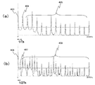
- the block diagram which shows the whole structure of one Embodiment of the MRI apparatus which concerns on this invention (a) is a conventional gradient magnetic field pulse, (b) is a diagram showing the time change of each gradient magnetic field pulse of Example 1.
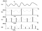
- (a) is a frequency distribution diagram obtained by Fourier transform of the conventional gradient magnetic field pulse of FIG. 2A (a)
- (b) is a frequency distribution diagram obtained by Fourier transform of the gradient magnetic field pulse of Example 1 of FIG. 2A (b).
- (a) is a conventional gradient magnetic field pulse
- (b) is a diagram showing the time change of each gradient magnetic field pulse of Example 2.
- (a) is a diagram showing a frequency distribution obtained by Fourier transform of the conventional gradient magnetic field pulse of FIG.
- (b) is a frequency distribution diagram obtained by Fourier transform of the gradient magnetic field pulse of Example 2 of FIG. 3A (b).
- (a) is a conventional gradient magnetic field pulse
- (b) is a diagram showing the time change of each gradient magnetic field pulse of Example 3.
- (a) is a frequency distribution diagram obtained by Fourier transform of the conventional gradient magnetic field pulse of FIG. 4A (a)
- (b) is a frequency distribution diagram obtained by Fourier transform of the gradient magnetic field pulse of Example 3 of FIG. 4A (b).
- (a) is a conventional gradient magnetic field pulse
- (b) is a diagram showing the time change of each gradient magnetic field pulse of Example 4.
- (a) is a frequency distribution diagram obtained by Fourier transform of the conventional gradient magnetic field pulse of FIG.
- FIG. 5A (a), (b) is a frequency distribution diagram obtained by Fourier transform of the gradient magnetic field pulse of Example 4 of FIG. 5A (b).
- Figure showing the frequency characteristics of the gradient magnetic field device's noise and the relationship between the noise level and frequency when the gradient magnetic field pulse period is changed The figure which shows an example of the operation screen which shows the silence parameter etc. in each Example of the noise suppression control of an MRI apparatus The figure explaining the calculation method of the excitation frequency of the same slice position at the time of polarity reversal of a gradient magnetic field pulse
- the MRI apparatus of the present embodiment captures a tomographic image of a subject using a nuclear magnetic resonance (NMR) phenomenon.
- the MRI apparatus includes a static magnetic field generation system 2, a gradient magnetic field generation system 3, a transmission system 5, a reception system 6, a signal processing system 7, a measurement control unit 4, an arithmetic processing unit ( CPU) 8.
- the static magnetic field generation system 2 is a vertical magnetic field system, it generates a uniform static magnetic field in a direction perpendicular to the body axis in the space around the subject 1. In the horizontal magnetic field method, a uniform static magnetic field is generated in the body axis direction.
- a permanent magnet type, normal conducting type or superconducting type static magnetic field generating source is arranged around the subject 1.
- the gradient magnetic field generating system 3 includes a gradient magnetic field coil 9 wound in the three-axis directions of X, Y, and Z, which is a coordinate system (stationary coordinate system) of the MRI apparatus, and a gradient magnetic field power source 10 that drives each gradient magnetic field coil. It consists of.
- the gradient magnetic field coil 9 and the gradient magnetic field power source 10 constitute a gradient magnetic field apparatus.
- the gradient magnetic field power supply 10 is provided corresponding to each of the gradient magnetic field coils 9 of the X, Y, and Z axes, and each gradient magnetic field power supply 10 is driven in accordance with a gradient magnetic field pulse output from the measurement control unit 4 described later.
- gradient magnetic fields Gx, Gy, and Gz are applied in the three-axis directions of X, Y, and Z.
- a slice-selected gradient magnetic field pulse (Gs) is applied in a direction orthogonal to the slice plane (imaging cross section) to set the slice plane for the subject 1, and the remaining planes orthogonal to the slice plane and orthogonal to each other are set.
- a phase encoding gradient magnetic field pulse (Gp) and a frequency encoding gradient magnetic field pulse (Gf) are applied in two directions, and position information in each direction is encoded into an echo signal.
- the measurement control unit 4 is a control unit that repeatedly applies a high-frequency magnetic field pulse (hereinafter referred to as “RF pulse”) having an excitation frequency and a gradient magnetic field pulse in a predetermined pulse sequence that is set.
- RF pulse high-frequency magnetic field pulse
- the measurement control unit 4 operates under the control of the arithmetic processing unit 8, and sends various commands necessary for collecting tomographic image data of the subject 1 to the transmission system 5, the gradient magnetic field generation system 3, and the reception system 6. It has become.
- the transmission system 5 irradiates the subject 1 with RF pulses in order to cause nuclear magnetic resonance to occur in the nuclear spins of the atoms constituting the living tissue of the subject 1, and the high-frequency oscillator 11, the modulator 12, and the high-frequency It comprises an amplifier 13 and a high frequency coil (transmission coil) 14a on the transmission side.
- the high-frequency pulse output from the high-frequency oscillator 11 is amplitude-modulated by the modulator 12 at a timing according to a command from the measurement control unit 4, and the amplitude-modulated high-frequency pulse is amplified by the high-frequency amplifier 13 and then close to the subject 1.
- the RF pulse is applied to the subject 1 by being supplied to the high-frequency coil 14a arranged in the manner described above.
- the receiving system 6 detects an echo signal (NMR signal) emitted by nuclear magnetic resonance of nuclear spins constituting the biological tissue of the subject 1, and receives a high-frequency coil (receiving coil) 14b on the receiving side and a signal amplifier 15 And a quadrature phase detector 16 and an A / D converter 17.
- NMR signal an echo signal
- the signals are divided into two orthogonal signals by the quadrature phase detector 16 at the timing according to the command from the measurement control unit 4, converted into digital quantities by the A / D converter 17, and sent to the signal processing system 7.
- the signal processing system 7 performs various data processing and display and storage of processing results, and is formed by including an external storage device such as an optical disk 19 and a magnetic disk 18 and a display 20 made up of a CRT or the like.
- an external storage device such as an optical disk 19 and a magnetic disk 18 and a display 20 made up of a CRT or the like.
- the arithmetic processing unit 8 executes processing such as signal processing and image reconstruction, and displays the tomographic image of the subject 1 as a result on the display 20.
- the data is recorded on the magnetic disk 18 of the external storage device.
- the operation unit 25 inputs various control information of the MRI apparatus and control information of processing performed by the signal processing system 7, and includes a trackball or mouse 23, a keyboard 24, and the like.
- the operation unit 25 is disposed in the vicinity of the display 20, and the operator controls various processes of the MRI apparatus interactively through the operation unit 25 while looking at the display 20.
- the high-frequency coil 14a and the gradient magnetic field coil 9 on the transmission side face the subject 1 in the static magnetic field space of the static magnetic field generation system 2 into which the subject 1 is inserted, in the case of the vertical magnetic field method. If the horizontal magnetic field method is used, the subject 1 is installed so as to surround it.
- the high-frequency coil 14b on the receiving side is installed so as to face or surround the subject 1.
- the imaging target nuclide of the MRI apparatus is a hydrogen nucleus (proton) that is a main constituent material of the subject as widely used in clinical practice.
- proton hydrogen nucleus
- the imaging information on the spatial distribution of proton density and the spatial distribution of the relaxation time of the excited state, the form or function of the human head, abdomen, limbs, etc. is imaged two-dimensionally or three-dimensionally.
- the noise suppression control which is a characteristic part of the present invention, executed by the measurement control unit 4 will be described by way of examples.
- the noise suppression control that shifts the frequency of noise generated by the gradient magnetic field device to the low frequency side, as a specific method of changing the waveform of the gradient magnetic field pulse during the repetition of the gradient magnetic field pulse of a certain period, A method of each embodiment described below, or a method in which those embodiments are appropriately combined can be applied.
- Example 1 is an example in which the polarity of at least one gradient magnetic field pulse is reversed and the waveform of a gradient magnetic field pulse train having a set number of repetitions is changed during repetition of a gradient magnetic field pulse with a constant period.
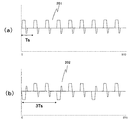
- FIG. 2A (a) shows a gradient magnetic field pulse 201 of slice selection applied at a constant period used in the gradient echo system.
- FIG. 2A (b) shows a gradient magnetic field pulse 202 for slice selection according to this embodiment.
- the gradient magnetic field pulse 202 of this embodiment is a pulse train pattern in which the polarity is inverted and the waveform is changed once every three repetitions of the gradient magnetic field pulse applied at a constant period. .
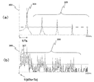
- a graph 203 in FIG. 2B (a) is a frequency distribution diagram obtained by performing Fourier transform on the gradient magnetic field pulse 201 in FIG. 2A (a).
- Reference numeral 204 denotes a frequency that is a fundamental tone of noise
- reference numeral 205 is a frequency that is a harmonic overtone of the fundamental tone.
- a graph 206 in FIG. 2B (b) is a frequency distribution diagram obtained by performing Fourier transform on the gradient magnetic field pulse 202 in FIG. 2A (b).
- the horizontal axis indicates the frequency
- the vertical axis indicates a value correlated with the noise intensity.
- reference numeral 207 in the figure is a frequency that becomes a fundamental tone of noise
- reference numeral 208 is a frequency that becomes a harmonic of the fundamental tone.
- the repetition interval (period) of the gradient magnetic field pulse 201 in FIG. 2A (a) is Ts
- a sound having a frequency of 1 / Ts (Hz) is generated.
- the gradient magnetic field pulse 202 is inverted once every three times as shown in FIG. 2A (b)
- the fundamental tone is changed to a sound having a frequency of 1/3 Ts (Hz).
- sound energy is distributed to each frequency, and the sound level of each frequency including the fundamental tone and the overtone is lowered.
- the excitation frequency of the RF pulse is calculated and changed so that the slice position does not change compared to before the inversion.
- the static magnetic field intensity B0 and the gradient magnetic field intensity at that position G + during forward rotation, G ⁇ during reverse rotation
- the example which repeats according to it was shown.
- the gradient magnetic field pulse for reversing the polarity is not limited to the head, but the polarity of the gradient magnetic field pulse at an arbitrary position and an arbitrary set number of m is reversed, and the frequency reduction effect is confirmed by Fourier transform and adopted. .
- the fundamental frequency (1 / Ts) when the fundamental frequency (1 / Ts) is multiplied by 1 / n, it is possible to invert up to m times with respect to n repetitions. Even if the noise suppression control is not performed, it is possible not to perform the noise suppression control when the fundamental frequency of the noise is a frequency of 20 Hz or less that does not affect humans.
- the polarity of at least one gradient magnetic field pulse is reversed to change the waveform of the gradient magnetic field pulse.
- the fundamental frequency of the noise of the gradient magnetic field device becomes 1 / nTs, and the frequency can be lowered.
- a person feels uncomfortable as the frequency is higher. Therefore, the discomfort of the person who is the subject can be reduced by shifting the frequency of the noise to the low frequency side.
- a user interface (UI) 701 shown in FIG. 7 can be displayed on the screen of the operation unit 25 or the display 20 of FIG. 7 includes a noise suppression control flag 702, a noise frequency 703 before suppression, a noise frequency 704 after suppression, and a parameter n705 of 1 / nTs (Hz).
- Reference numeral 706 indicates the type of noise suppression control, and specifically indicates the type of an example of noise suppression control.
- the user can select whether to perform noise suppression control by turning on / off the noise suppression control flag 702.
- the noise frequencies 703 and 704 before and after suppression may be displayed, or the frequencies may be selected by the user.
- 1 / Ts (Hz) calculated from the period Ts of the gradient magnetic field pulse of slice selection is displayed, and an arbitrary period and frequency (1 / nTs) are selected by selecting the setting repetition number n705 as a parameter. You may be able to do it.
- n corresponds to the number of slices
- 1 / Ts, 1 / 2Ts, ..., 1 / ( n-1) Ts and 1 / nTs (Hz) can be selected. It is desirable that the number be divisible by n.
- the noise suppression control type 706 can select a combination of the embodiments according to the noise suppression control.
- Example 1 is not limited to inversion between different slices, but between the same slices between 90 ° and 180 ° RF pulses of the spin echo system, or between the same slices of the 180 ° RF pulse of the first spin echo system. Can be applied.
- the noise suppression control by polarity reversal of the gradient magnetic field of the first embodiment is not limited to the slice selection gradient magnetic field pulse, but can be applied to the noise suppression of the frequency encoding gradient magnetic field pulse and the phase encoding gradient magnetic field pulse. it can. In this case, the arrangement of the k space of the measured magnetic resonance image data may be reversed at the same time. Further, the present invention can be applied to noise suppression of a crusher pulse applied in order to phase-disperse transverse magnetization of protons selectively excited by an RF pulse.
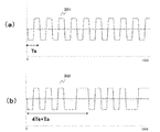
- Example 2 is an example in which the waveform of a gradient magnetic field pulse train having a set number of repetitions is changed by increasing the application time (pulse width) of at least one gradient magnetic field pulse during repetition of a gradient magnetic field pulse having a constant period.
- FIG. 3A (a) shows a frequency-encoded gradient magnetic field pulse 301 applied at a fixed period used for echo planar imaging or the like.
- FIG. 3A (b) shows the frequency-encoded gradient magnetic field pulse 302 of this embodiment.
- the gradient magnetic field pulse 302 of the present embodiment when counting the upside-down inversion of the frequency-encoded gradient magnetic field pulse 302 applied at a constant period Ts as the repetition number “1”, is set to the set repetition number n (
- a graph 303 in FIG. 3B (a) is a result of Fourier transform of the gradient magnetic field pulse 301.
- Reference numeral 304 indicates a fundamental frequency
- reference numeral 305 indicates a harmonic frequency.
- a graph 306 in FIG. 3B (b) is a result of Fourier transform of the gradient magnetic field pulse 302 in FIG. 3A (b), where the horizontal axis indicates the frequency and the vertical axis is a value correlated with the noise intensity.
- Numeral 307 is a frequency that becomes a fundamental tone
- numeral 308 is a frequency that becomes a harmonic.
- the waveform of the gradient magnetic field pulse is changed by increasing the application time (pulse width) of at least one gradient magnetic field pulse during repetition of the gradient magnetic field pulse having a constant period.
- the application interval (cycle) of a plurality of gradient magnetic field pulses connected to the gradient magnetic field pulse whose pulse width is increased can be lengthened.
- a gradient magnetic field device that is repeatedly driven with a gradient magnetic field pulse with a constant period Ts is driven with a pulse train with a period (nTs + Ta). It will be. As a result, the frequency of the fundamental sound of the gradient magnetic field device becomes 1 / (nTs + Ta) and can be lowered, and the emitted sound also shifts from a high frequency to a low frequency. It is possible to reduce the discomfort of the person who is.
- the echo acquisition time TE is not changed in order to maintain the image contrast.
- the target for changing the application time of the gradient magnetic field is not limited to the frequency-encoded gradient magnetic field pulse, and may be a slice selection gradient magnetic field pulse or a phase encode pulse. Further, it may be a crusher pulse applied in order to phase-disperse the transverse magnetization of protons selectively excited by the RF pulse. Furthermore, it may be implemented in combination with Example 1, and the combination can be determined according to the pulse shape used for each measurement.
- Example 3 is an example in which the waveform of a gradient magnetic field pulse train having a set number of repetitions is changed by moving the application timing of at least one gradient magnetic field pulse in the time axis direction during the repetition of a gradient magnetic field pulse with a constant period.
- the waveform of the pulse train of the gradient magnetic field pulse is changed by changing the application interval of the gradient magnetic field pulse.
- the gradient magnetic field is applied at long-period intervals, and the emitted sound also shifts from a high frequency to a low frequency.
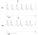
- FIG. 4A (a) shows a slice-selected gradient magnetic field pulse 401 applied at a constant period.
- the application interval of the gradient magnetic field pulse of slice selection applied at a fixed period in this embodiment is changed in the pulse train of the set repetition number 2 and the application interval of the set magnetic field pulse of the set number 1 is changed.
- a gradient magnetic field pulse 402 having a pulse train pattern with a changed waveform is shown.
- a graph 403 in FIG. 4B (a) is a frequency distribution diagram obtained by Fourier transforming the gradient magnetic field pulse 401 in FIG. 4A (a).
- Reference numeral 404 is a frequency that is a fundamental sound of noise
- reference numeral 405 is a harmonic of the fundamental sound. This is the frequency.
- a graph 406 in FIG. 4B (b) is a frequency distribution diagram obtained by Fourier transforming the gradient magnetic field pulse 402 in FIG. 4A (b).
- the horizontal axis indicates the frequency
- the vertical axis is a value correlated with the noise intensity.
- reference numeral 407 in the figure denotes a frequency that becomes a fundamental tone of noise
- reference numeral 408 denotes a frequency that becomes a harmonic of the fundamental tone.
- the interval (period) of the gradient magnetic field pulse 401 in FIG. 4A (a) is Ts
- a sound with a fundamental frequency of 1 / Ts (Hz) is generated.
- Change the application interval of magnetic field pulses That is, the application interval of the first and second gradient magnetic field pulses in the gradient magnetic field pulse train having the set repetition number 2 is shortened.
- the application timing of the second gradient magnetic field pulse is moved in the direction of the first gradient magnetic field pulse to shorten the interval with the first gradient magnetic field pulse.
- the period of the gradient magnetic field pulse train of the set repetition number n shown in FIG.4A (b) becomes nTs.As a result, as shown in FIG.4B (b), the sound generated from the gradient magnetic field device has a fundamental tone.
- the frequency changes to 1 / (2Ts) (Hz).
- auxiliary functions such as a user interface (UI) 701 shown in FIG. 7 can be added.
- the target for changing the application time of the gradient magnetic field is not limited to the slice selection gradient magnetic field pulse. Should be done correctly. Further, it may be a crusher pulse applied in order to phase-disperse the transverse magnetization of protons selectively excited by the RF pulse. Furthermore, it may be implemented in combination with other embodiments.
- Example 4 of the present invention will be described.
- the fourth embodiment is an example in which the gradient magnetic field pulse train is changed in intensity by changing the intensity of the gradient magnetic field pulse during the repetition of the gradient magnetic field pulse having a constant period.
- FIG. 5A (a) shows a slice-selective gradient magnetic field pulse 501 applied at a constant period.
- a graph 503 in FIG. 5B (a) is a frequency distribution diagram obtained by performing Fourier transform on the gradient magnetic field pulse 501 shown in FIG. 5A (a).
- Reference numeral 504 denotes a fundamental frequency
- reference numeral 505 denotes a harmonic frequency.
- a graph 506 in FIG. 5B (b) is a frequency distribution diagram obtained by performing Fourier transform on the gradient magnetic field pulse 502 in FIG. 5A (b).
- the horizontal axis represents frequency
- the vertical axis represents a value correlated with noise intensity.
- Reference numeral 507 denotes a frequency that becomes a fundamental tone
- reference numeral 508 denotes a frequency that becomes a harmonic. At this time, sound energy is distributed to each frequency, and the sound level of each frequency including the fundamental tone and the overtone is lowered.
- the long period Gradient magnetic field pulses are applied at intervals, and the emitted sound also shifts from high frequency to low frequency.
- the interval (period) of the gradient magnetic field pulses in FIG. 5A (a) is Ts
- the intensity of the crusher pulse applied to the gradient magnetic field pulse is that the sound of the fundamental frequency is 1 / Ts (Hz). Is gradually changed to a sound having a frequency of 1 / (4Ts) (Hz) as shown in FIG. 5B (b).
- the discomfort of the person who is the subject can be reduced as in the first to third embodiments.
- sound energy is distributed to each frequency, and the sound level of each frequency including the fundamental tone and the overtone is lowered.
- auxiliary functions such as a user interface (UI) 701 shown in FIG. 7 can be added.
- the target for changing the intensity of the gradient magnetic field pulse is not limited to the crusher pulse, and even if the gradient magnetic field pulse is a slice selection, the slice profile may be the same. Moreover, even if it is a phase encoding pulse, it is sufficient if the arrangement of the k space is not changed after the change. Further, it may be implemented in combination with the first embodiment, the second embodiment, or the third embodiment.
- Embodiment 5 of the present invention will be described with reference to FIG.
- the present embodiment is an example in which noise suppression is performed by changing the frequency more effectively by preparing the frequency characteristics of the noise of the gradient magnetic field device generated by the gradient magnetic field pulse in advance.
- the horizontal axis represents the frequency
- the vertical axis represents the noise level [dBA] for each gradient magnetic field pulse intensity of the gradient magnetic field apparatus
- reference numeral 601 represents the frequency characteristic of the noise level of the gradient magnetic field apparatus.
- (B) is a graph of the sound level of the frequency of the fundamental tone 1 / Ts when the period of the gradient magnetic field pulse is Ts, and shows the noise level when the gradient magnetic field apparatus has the frequency characteristic 601. Yes.
- FIG. 5C is a graph showing the sound level of the frequency of the fundamental tone 1/2 Ts when the gradient magnetic field pulse period is 2 Ts, and shows the noise level corresponding to the frequency characteristic 601 of the gradient magnetic field device.
- FIG. 4D is a graph showing the sound level of the frequency of the fundamental tone 1/3 Ts when the period of the gradient magnetic field pulse is 3 Ts, and shows the noise level corresponding to the frequency characteristic 601 of the gradient magnetic field device.
- the noise level with respect to the noise suppression frequency of Fig. 11 (b) to (d) is predicted in advance.
- the noise level is the smallest in (d)
- the setting repetition number n that becomes 1 / 3Ts in noise suppression control and the setting number m that changes the waveform are automatically selected. Can be changed.
- the noise suppression effect for example, the noise before and after the change [dBA] can be notified to the user.
- the frequency of the fundamental tone of the noise of the gradient magnetic field device can be lowered by applying the noise suppression control of Embodiments 1 to 4 alone or in combination as appropriate. Furthermore, if Example 5 is combined, noise suppression control can be performed appropriately. At that time, the measurement control unit 4 may allow the user to select a combination of the noise suppression controls described in the first to fifth embodiments.
- the measurement control unit 4 may change the waveform of the gradient magnetic field pulse when the constant period Ts of the gradient magnetic field pulse is shorter than a predetermined set period. Further, the measurement control unit 4 may notify the user that any noise suppression control including the first to fifth embodiments is being performed.
- the present invention sets the number of repetitions of the gradient magnetic field pulse having a constant period Ts to n (where n is a natural number), changes the pulse train pattern of the gradient magnetic field pulse train of the set repetition number n, and lengthens the pulse train pattern. .
- the purpose of the present invention is to lower the frequency of the fundamental sound of the noise generated from the gradient magnetic field device by repeatedly driving the gradient magnetic field device with the gradient magnetic field pulse train of the set repetition number n having a long period. That is, the gradient magnetic field device is repeatedly driven in units of a pulse train pattern with a reduced frequency.
- the gradient magnetic field device that is repeatedly driven by the gradient magnetic field pulse having the constant cycle Ts is driven by the repetition cycle nTs of the pulse train pattern unit.
- the noise frequency of the gradient magnetic field device becomes 1 / nTs and the frequency is lowered.
- 1 subject 2 static magnetic field generation system, 3 gradient magnetic field generation system, 4 measurement control unit, 5 transmission system, 6 reception system, 7 signal processing system, 8 arithmetic processing unit, 9 gradient magnetic field coil, 10 gradient magnetic field power supply, 11 High frequency oscillator, 12 modulator, 13 high frequency amplifier, 14a high frequency coil (transmitting coil), 14b high frequency coil (receiving coil), 15 signal amplifier, 16 quadrature phase detector, 17 A / D converter, 18 magnetic disk, 19 optical disk , 20 display, 21 ROM, 22 RAM, 23 trackball or mouse, 24 keyboard
Landscapes
- Physics & Mathematics (AREA)
- Condensed Matter Physics & Semiconductors (AREA)
- General Physics & Mathematics (AREA)
- Engineering & Computer Science (AREA)
- Signal Processing (AREA)
- High Energy & Nuclear Physics (AREA)
- Health & Medical Sciences (AREA)
- General Health & Medical Sciences (AREA)
- Nuclear Medicine, Radiotherapy & Molecular Imaging (AREA)
- Radiology & Medical Imaging (AREA)
- Magnetic Resonance Imaging Apparatus (AREA)
Abstract
Description
Claims (15)
- 静磁場中に置かれた被検体にパルス状の傾斜磁場を印加する傾斜磁場装置と、前記傾斜磁場装置を傾斜磁場パルスにより駆動して磁気共鳴画像データを計測する計測制御部を備えた磁気共鳴イメージング装置であって、
前記計測制御部は、一定周期の前記傾斜磁場パルスの繰返し中に少なくとも一つの前記傾斜磁場パルスの波形を変えて、前記傾斜磁場装置が発生する騒音の周波数を低周波側に移行させる騒音抑制制御を行うことを特徴とする磁気共鳴イメージング装置。 - 前記計測制御部は、一定周期の前記傾斜磁場パルスの設定繰返し数毎に、前記傾斜磁場パルスの波形を変えて騒音抑制制御を行うことを特徴とする請求項1に記載の磁気共鳴イメージング装置。
- 前記計測制御部は、一定周期の前記傾斜磁場パルスの繰返し中に、少なくとも一つの前記傾斜磁場パルスの極性を反転させて前記騒音抑制制御を行うことを特徴とする請求項1に記載の磁気共鳴イメージング装置。
- 前記計測制御部は、一定周期の前記傾斜磁場パルスの繰返し中に、少なくとも一つの前記傾斜磁場パルスの印加時間を増大して前記騒音抑制制御を行うことを特徴とする請求項1に記載の磁気共鳴イメージング装置。
- 前記計測制御部は、一定周期の前記傾斜磁場パルスの繰返し中に、少なくとも一つの前記傾斜磁場パルスの印加タイミングを時間軸方向に移動して前記騒音抑制制御を行うことを特徴とする請求項1に記載の磁気共鳴イメージング装置。
- 前記計測制御部は、一定周期の前記傾斜磁場パルスの繰返し中に、前記傾斜磁場パルスの強度を変えて前記騒音抑制制御を行うことを特徴とする請求項1に記載の磁気共鳴イメージング装置。
- 前記計測制御部は、前記傾斜磁場パルスに付加するクラッシャーパルスの強度を漸次変えて前記騒音抑制制御を行うことを特徴とする請求項6に記載の磁気共鳴イメージング装置。
- 前記計測制御部は、SSFP系、GRE系、FSE系、EPI系のパルスシーケンスにより前記磁気共鳴画像データを計測することを特徴とする請求項1に記載の磁気共鳴イメージング装置。
- 前記計測制御部は、前記傾斜磁場パルスの前記一定周期が、設定周期よりも短い場合に、前記傾斜磁場パルスの波形を変えることを特徴とする請求項1に記載の磁気共鳴イメージング装置。
- 前記計測制御部は、前記騒音抑制制御を行っていることをユーザに知らせることを特徴とする請求項1に記載の磁気共鳴イメージング装置。
- 前記計測制御部は、前記騒音抑制制御による騒音周波数をユーザに選ばせることを特徴とする請求項1に記載の磁気共鳴イメージング装置。
- 前記計測制御部は、
一定周期の前記傾斜磁場パルスの設定繰返し数ごとに、前記傾斜磁場パルスの波形を変えること、
一定周期の前記傾斜磁場パルスの繰返し中に、少なくとも一つの前記傾斜磁場パルスの極性を反転させること、
一定周期の前記傾斜磁場パルスの繰返し中に、少なくとも一つの前記傾斜磁場パルスの印加時間を増大すること、
一定周期の前記傾斜磁場パルスの繰返し中に、少なくとも一つの前記傾斜磁場パルスの印加タイミングを時間軸方向に移動すること、
の内の2つ以上の組み合わせを騒音抑制制御として行うことを特徴とする請求項1に記載の磁気共鳴イメージング装置。 - 前記計測制御部は、前記騒音抑制制御の組み合わせをユーザに選ばせることを特徴とする請求項12記載の磁気共鳴イメージング装置。
- 前記計測制御部は、前記傾斜磁場装置の騒音の特性に基づいて、騒音の基音が最も小さくなる前記傾斜磁場パルスの繰返しの設定繰返し数を選択することを特徴とする請求項2記載の磁気共鳴イメージング装置。
- 静磁場中に置かれた被検体にパルス状の傾斜磁場を印加する傾斜磁場装置と、前記傾斜磁場装置を傾斜磁場パルスにより駆動して磁気共鳴画像データを計測する計測制御部を備えた磁気共鳴イメージング装置における騒音低減方法であって、
一定周期の前記傾斜磁場パルスの繰返し中に少なくとも一つの前記傾斜磁場パルスの波形を変えて、前記傾斜磁場装置が発生する騒音の周波数を低周波側に移行させるステップと、
前記波形を変えられた傾斜磁場パルスを用いて前記被検体から磁気共鳴画像データを計測するステップと、
を有することを特徴とする騒音低減方法。
Priority Applications (3)
| Application Number | Priority Date | Filing Date | Title |
|---|---|---|---|
| CN201580004491.XA CN105939661B (zh) | 2014-01-27 | 2015-01-15 | 磁共振成像装置以及降噪方法 |
| US15/104,751 US10393834B2 (en) | 2014-01-27 | 2015-01-15 | Magnetic resonance imaging apparatus and noise reduction method |
| JP2015558816A JP6419730B2 (ja) | 2014-01-27 | 2015-01-15 | 磁気共鳴イメージング装置及び騒音低減方法 |
Applications Claiming Priority (2)
| Application Number | Priority Date | Filing Date | Title |
|---|---|---|---|
| JP2014-012796 | 2014-01-27 | ||
| JP2014012796 | 2014-01-27 |
Publications (1)
| Publication Number | Publication Date |
|---|---|
| WO2015111493A1 true WO2015111493A1 (ja) | 2015-07-30 |
Family
ID=53681299
Family Applications (1)
| Application Number | Title | Priority Date | Filing Date |
|---|---|---|---|
| PCT/JP2015/050902 WO2015111493A1 (ja) | 2014-01-27 | 2015-01-15 | 磁気共鳴イメージング装置及び騒音低減方法 |
Country Status (4)
| Country | Link |
|---|---|
| US (1) | US10393834B2 (ja) |
| JP (1) | JP6419730B2 (ja) |
| CN (1) | CN105939661B (ja) |
| WO (1) | WO2015111493A1 (ja) |
Cited By (2)
| Publication number | Priority date | Publication date | Assignee | Title |
|---|---|---|---|---|
| CN109414214A (zh) * | 2016-07-28 | 2019-03-01 | 株式会社日立制作所 | 磁共振成像装置 |
| WO2022181817A1 (ja) | 2021-02-26 | 2022-09-01 | ビークルエナジージャパン株式会社 | 組電池及び電源装置 |
Families Citing this family (3)
| Publication number | Priority date | Publication date | Assignee | Title |
|---|---|---|---|---|
| DE102014221950B3 (de) * | 2014-10-28 | 2016-04-21 | Siemens Aktiengesellschaft | Geräuschreduzierung bei selektiver MR-Anregung |
| US11353527B2 (en) | 2019-07-19 | 2022-06-07 | Shanghai United Imaging Healthcare Co., Ltd. | Systems and methods for waveform determination in magnetic resonance imaging |
| CN112826494B (zh) * | 2020-12-30 | 2023-05-23 | 上海联影医疗科技股份有限公司 | Mr设备振动和声学噪声消减方法、系统、装置及存储介质 |
Citations (5)
| Publication number | Priority date | Publication date | Assignee | Title |
|---|---|---|---|---|
| JP4360912B2 (ja) * | 2001-11-26 | 2009-11-11 | コーニンクレッカ フィリップス エレクトロニクス エヌ ヴィ | 音響ノイズが低減された磁気共鳴撮像方法 |
| JP2011530371A (ja) * | 2008-08-14 | 2011-12-22 | コーニンクレッカ フィリップス エレクトロニクス エヌ ヴィ | Mriノイズ美化 |
| WO2013165571A1 (en) * | 2012-04-30 | 2013-11-07 | The General Hospital Corporation | System and method for quiet magnetic resonance imaging |
| WO2014189929A1 (en) * | 2013-05-23 | 2014-11-27 | General Electric Company | Systems and methods for reducing magnetic resonance (mr) imaging acoustic noise in mr inflow imaging |
| US20140347050A1 (en) * | 2013-05-22 | 2014-11-27 | General Electric Company | System and method for reducing acoustic noise level in mr imaging |
Family Cites Families (18)
| Publication number | Priority date | Publication date | Assignee | Title |
|---|---|---|---|---|
| DE4035410C2 (de) * | 1989-11-20 | 2000-03-16 | Siemens Ag | Pulssequenz nach dem Echoplanarverfahren |
| EP0554584A1 (en) * | 1991-11-29 | 1993-08-11 | Koninklijke Philips Electronics N.V. | Magnetic resonance device and signal combination device |
| DE19910018C1 (de) * | 1999-03-08 | 2000-10-19 | Siemens Ag | Verfahren zum Betrieb eines Magnetresonanztomographiegeräts |
| AU2003237848A1 (en) * | 2002-05-15 | 2003-12-02 | University Of Virginia Patent Foundation | Method and system for rapid magnetic resonance imaging of gases with reduced diffusion-induced signal loss |
| JP4497973B2 (ja) * | 2004-03-24 | 2010-07-07 | 株式会社東芝 | 磁気共鳴イメージング装置 |
| US7683614B2 (en) * | 2006-04-27 | 2010-03-23 | Stefan Posse | Magnetic resonance spectroscopy with sparse spectral sampling and interleaved dynamic shimming |
| EP2283373B1 (en) * | 2008-04-28 | 2021-03-10 | Cornell University | Accurate quantification of magnetic susceptibility in molecular mri |
| US9833168B2 (en) * | 2011-06-06 | 2017-12-05 | St. Jude Medical, Atrial Fibrillation Division, Inc. | Noise tolerant localization systems and methods |
| DE102011083619B4 (de) * | 2011-09-28 | 2023-01-26 | Siemens Healthcare Gmbh | Verfahren zur Erzeugung einer Serie von MR-Bildern zur Überwachung einer Position eines in einem Untersuchungsgebiet befindlichen Interventionsgeräts, Magnetresonanzanlage und elektronisch lesbarer Datenträger |
| US9588207B2 (en) * | 2011-10-06 | 2017-03-07 | National Institutes of Health (NIH), U.S. Dept. of Health and Human Services (DHHS), The United States of America NIH Division of Extramural Inventions and Technology Resources (DEITR) | System for reconstructing MRI images acquired in parallel |
| DE102012203512B4 (de) * | 2012-02-03 | 2014-02-13 | Siemens Aktiengesellschaft | Ermittlung einer MR-Messsequenz mittels eines Gradienten-Optimierungsverfahrens |
| DE102012219010B4 (de) * | 2012-10-18 | 2014-04-30 | Siemens Aktiengesellschaft | Optimierung einer Pulssequenz für eine Magnetresonanzanlage |
| JP6013137B2 (ja) * | 2012-10-26 | 2016-10-25 | 東芝メディカルシステムズ株式会社 | 磁気共鳴イメージング装置および周波数シフト量測定方法 |
| JP6277201B2 (ja) * | 2013-01-15 | 2018-02-07 | コーニンクレッカ フィリップス エヌ ヴェKoninklijke Philips N.V. | 音響ノイズ放射が抑制される動脈スピンラベリング及びその作動方法 |
| DE102013202559B3 (de) * | 2013-02-18 | 2014-08-21 | Siemens Aktiengesellschaft | Optimierung einer MR-Pulssequenz durch automatisches Optimieren von Gradientenpulsen in veränderbaren Intervallen |
| DE102013213255B4 (de) * | 2013-07-05 | 2017-06-08 | Siemens Healthcare Gmbh | Beschleunigte Bestimmung von Gradientenverläufen auf der Grundlage von vorherigen Gradientenverläufen |
| DE102013218475B4 (de) * | 2013-09-16 | 2015-10-22 | Siemens Aktiengesellschaft | Geräuschsoptimierung einer Magnetresonanz-Sequenz durch Anhebung einer Pulsbandweite |
| US9612300B2 (en) * | 2013-11-25 | 2017-04-04 | Wisconsin Alumni Research Foundation | System and method for object-based initialization of magnetic field inhomogeneity in magnetic resonance imaging |
-
2015
- 2015-01-15 CN CN201580004491.XA patent/CN105939661B/zh active Active
- 2015-01-15 JP JP2015558816A patent/JP6419730B2/ja active Active
- 2015-01-15 US US15/104,751 patent/US10393834B2/en active Active
- 2015-01-15 WO PCT/JP2015/050902 patent/WO2015111493A1/ja active Application Filing
Patent Citations (5)
| Publication number | Priority date | Publication date | Assignee | Title |
|---|---|---|---|---|
| JP4360912B2 (ja) * | 2001-11-26 | 2009-11-11 | コーニンクレッカ フィリップス エレクトロニクス エヌ ヴィ | 音響ノイズが低減された磁気共鳴撮像方法 |
| JP2011530371A (ja) * | 2008-08-14 | 2011-12-22 | コーニンクレッカ フィリップス エレクトロニクス エヌ ヴィ | Mriノイズ美化 |
| WO2013165571A1 (en) * | 2012-04-30 | 2013-11-07 | The General Hospital Corporation | System and method for quiet magnetic resonance imaging |
| US20140347050A1 (en) * | 2013-05-22 | 2014-11-27 | General Electric Company | System and method for reducing acoustic noise level in mr imaging |
| WO2014189929A1 (en) * | 2013-05-23 | 2014-11-27 | General Electric Company | Systems and methods for reducing magnetic resonance (mr) imaging acoustic noise in mr inflow imaging |
Cited By (2)
| Publication number | Priority date | Publication date | Assignee | Title |
|---|---|---|---|---|
| CN109414214A (zh) * | 2016-07-28 | 2019-03-01 | 株式会社日立制作所 | 磁共振成像装置 |
| WO2022181817A1 (ja) | 2021-02-26 | 2022-09-01 | ビークルエナジージャパン株式会社 | 組電池及び電源装置 |
Also Published As
| Publication number | Publication date |
|---|---|
| US20170003362A1 (en) | 2017-01-05 |
| JP6419730B2 (ja) | 2018-11-07 |
| US10393834B2 (en) | 2019-08-27 |
| JPWO2015111493A1 (ja) | 2017-03-23 |
| CN105939661B (zh) | 2019-03-08 |
| CN105939661A (zh) | 2016-09-14 |
Similar Documents
| Publication | Publication Date | Title |
|---|---|---|
| JP6419730B2 (ja) | 磁気共鳴イメージング装置及び騒音低減方法 | |
| KR20130050846A (ko) | 자기 공명 영상 장치 및 그 제어 방법 | |
| US20130069650A1 (en) | Magnetic resonance imaging apparatus and high-frequency magnetic field pulse modulation method | |
| WO2010053012A1 (ja) | 磁気共鳴イメージング装置及び方法 | |
| JP2014502910A (ja) | インターリーブスピンロッキングイメージング | |
| JP6615184B2 (ja) | 磁気共鳴イメージング装置 | |
| JP5808659B2 (ja) | 磁気共鳴イメージング装置及びT1ρイメージング法 | |
| JP5159200B2 (ja) | 磁気共鳴イメージング装置 | |
| JP5536346B2 (ja) | 磁気共鳴イメージング装置 | |
| JP5602208B2 (ja) | 磁気共鳴イメージング装置及び磁気共鳴イメージング方法 | |
| WO2015076082A1 (ja) | 磁気共鳴イメージング装置 | |
| JP5352130B2 (ja) | 磁気共鳴イメージング装置 | |
| JP6157976B2 (ja) | 磁気共鳴イメージング装置、及び方法 | |
| JP5942265B2 (ja) | 磁気共鳴イメージング装置及びrfパルス制御方法 | |
| JP5758230B2 (ja) | 磁気共鳴イメージング装置及び反転rfパルス位相制御方法 | |
| JP2016131847A (ja) | 磁気共鳴イメージング装置および磁気共鳴イメージング方法 | |
| JP2018114163A (ja) | 磁気共鳴イメージング装置 | |
| JP2009291388A (ja) | 磁気共鳴イメージング方法及び磁気共鳴イメージング装置 | |
| JP2016214630A (ja) | 磁気共鳴イメージング装置、及び作動方法 | |
| JP2017123888A (ja) | 磁気共鳴イメージング装置及びリフェーズ傾斜磁場印加方法 | |
| JP6233965B2 (ja) | 磁気共鳴イメージング装置及びrfシミング方法 | |
| JP5283213B2 (ja) | 磁気共鳴イメージング装置 | |
| JP2015128552A (ja) | 磁気共鳴イメージング装置、及びその磁場印加方法 | |
| JP2010233799A (ja) | Mriにおけるハイブリッド法及びmri装置 | |
| JP2017006522A (ja) | 磁気共鳴イメージング装置及びその磁場印加方法 |
Legal Events
| Date | Code | Title | Description |
|---|---|---|---|
| 121 | Ep: the epo has been informed by wipo that ep was designated in this application |
Ref document number: 15740577 Country of ref document: EP Kind code of ref document: A1 |
|
| ENP | Entry into the national phase |
Ref document number: 2015558816 Country of ref document: JP Kind code of ref document: A |
|
| WWE | Wipo information: entry into national phase |
Ref document number: 15104751 Country of ref document: US |
|
| NENP | Non-entry into the national phase |
Ref country code: DE |
|
| 122 | Ep: pct application non-entry in european phase |
Ref document number: 15740577 Country of ref document: EP Kind code of ref document: A1 |