EP0554584A1 - Magnetic resonance device and signal combination device - Google Patents
Magnetic resonance device and signal combination device Download PDFInfo
- Publication number
- EP0554584A1 EP0554584A1 EP92203603A EP92203603A EP0554584A1 EP 0554584 A1 EP0554584 A1 EP 0554584A1 EP 92203603 A EP92203603 A EP 92203603A EP 92203603 A EP92203603 A EP 92203603A EP 0554584 A1 EP0554584 A1 EP 0554584A1
- Authority
- EP
- European Patent Office
- Prior art keywords
- signal
- magnetic resonance
- frequency
- coil elements
- resonance device
- Prior art date
- Legal status (The legal status is an assumption and is not a legal conclusion. Google has not performed a legal analysis and makes no representation as to the accuracy of the status listed.)
- Withdrawn
Links
- 238000001514 detection method Methods 0.000 claims abstract description 10
- 238000012545 processing Methods 0.000 abstract description 14
- 230000000717 retained effect Effects 0.000 abstract 1
- 238000000034 method Methods 0.000 description 7
- 238000005259 measurement Methods 0.000 description 4
- 230000005540 biological transmission Effects 0.000 description 3
- 238000010276 construction Methods 0.000 description 3
- 230000005415 magnetization Effects 0.000 description 3
- 238000013461 design Methods 0.000 description 2
- 230000009466 transformation Effects 0.000 description 2
- 230000001427 coherent effect Effects 0.000 description 1
- 238000012937 correction Methods 0.000 description 1
- 230000008878 coupling Effects 0.000 description 1
- 238000010168 coupling process Methods 0.000 description 1
- 238000005859 coupling reaction Methods 0.000 description 1
- 230000001419 dependent effect Effects 0.000 description 1
- 230000005284 excitation Effects 0.000 description 1
- 238000001914 filtration Methods 0.000 description 1
- 238000005070 sampling Methods 0.000 description 1
- 238000000926 separation method Methods 0.000 description 1
- 230000001629 suppression Effects 0.000 description 1
Images

Classifications
-
- G—PHYSICS
- G01—MEASURING; TESTING
- G01R—MEASURING ELECTRIC VARIABLES; MEASURING MAGNETIC VARIABLES
- G01R33/00—Arrangements or instruments for measuring magnetic variables
- G01R33/20—Arrangements or instruments for measuring magnetic variables involving magnetic resonance
- G01R33/44—Arrangements or instruments for measuring magnetic variables involving magnetic resonance using nuclear magnetic resonance [NMR]
- G01R33/48—NMR imaging systems
- G01R33/54—Signal processing systems, e.g. using pulse sequences ; Generation or control of pulse sequences; Operator console
-
- G—PHYSICS
- G01—MEASURING; TESTING
- G01R—MEASURING ELECTRIC VARIABLES; MEASURING MAGNETIC VARIABLES
- G01R33/00—Arrangements or instruments for measuring magnetic variables
- G01R33/20—Arrangements or instruments for measuring magnetic variables involving magnetic resonance
- G01R33/28—Details of apparatus provided for in groups G01R33/44 - G01R33/64
- G01R33/32—Excitation or detection systems, e.g. using radio frequency signals
- G01R33/34—Constructional details, e.g. resonators, specially adapted to MR
- G01R33/341—Constructional details, e.g. resonators, specially adapted to MR comprising surface coils
- G01R33/3415—Constructional details, e.g. resonators, specially adapted to MR comprising surface coils comprising arrays of sub-coils, i.e. phased-array coils with flexible receiver channels
-
- G—PHYSICS
- G01—MEASURING; TESTING
- G01R—MEASURING ELECTRIC VARIABLES; MEASURING MAGNETIC VARIABLES
- G01R33/00—Arrangements or instruments for measuring magnetic variables
- G01R33/20—Arrangements or instruments for measuring magnetic variables involving magnetic resonance
- G01R33/28—Details of apparatus provided for in groups G01R33/44 - G01R33/64
- G01R33/32—Excitation or detection systems, e.g. using radio frequency signals
- G01R33/36—Electrical details, e.g. matching or coupling of the coil to the receiver
- G01R33/3621—NMR receivers or demodulators, e.g. preamplifiers, means for frequency modulation of the MR signal using a digital down converter, means for analog to digital conversion [ADC] or for filtering or processing of the MR signal such as bandpass filtering, resampling, decimation or interpolation
Definitions
- the invention relates to a magnetic resonance device, comprising a main field magnet for generating a steady magnetic field in a measuring space for accommodating an object, a coil system for generating a gradient magnetic field, and an RF coil system which consists of several coil elements for detection of magnetic resonance signals to be generated in the object.
- a magnetic resonance device of this kind is known from the international Patent Application WO 89/05115.
- the magnetic resonance device disclosed in the cited Patent Application is used to form partial images from magnetic resonance signals originating from separate coil elements.
- the partial images are combined so as to form an ultimate image of a sub-volume of the object measured by means of the RF coil system.
- the signals from the individual coil elements are detected in separate detection channels, are sampled and subsequently applied to processing means, completely independently from one another, in order to form the partial images and the ultimate image.
- the combination of the partial images so as to form an ultimate image should be executed pixel-wise in order to prevent the addition of noise.
- a magnetic resonance device in accordance with the invention is characterized in that the magnetic resonance device comprises a signal combination device which is operative to shift frequency ranges of individual coil elements in respect of frequency and to combine the shifted frequency ranges so that on a sum output of the signal combination device there is formed a sum signal in which the frequency ranges are at least substantially separated from one another. Because signal combination already takes place in the RF section of the magnetic resonance device, the construction of each detection channel may be simpler. The signal shifting and combination are executed so that the advantages of a device comprising separate channels up to data processing are maintained, i.e. the orientation of the coil system relative to a measuring gradient can still be chosen completely as desired.
- An embodiment of a magnetic resonance device in accordance with the invention is characterized in that the signal combination device for the individual coil elements comprises first frequency shifting devices which are coupled to the coil elements and outputs of which are coupled to fixed or adjustable bandpass filters which are coupled to a signal summing device for supplying the sum signal.
- the signal combination device for the individual coil elements comprises first frequency shifting devices which are coupled to the coil elements and outputs of which are coupled to fixed or adjustable bandpass filters which are coupled to a signal summing device for supplying the sum signal.
- the signal combination device for the individual coil elements comprises second frequency shifting devices which are connected so as to precede the signal summing device, or comprises one second frequency shifting device which is connected subsequent to the signal summing device.
- the hardware connected subsequent to the signal combination device may be standard hardware.
- a preferred embodiment of a magnetic resonance device is characterized in that in the presence of second frequency shifting devices connected so as to precede the signal summing device, the bandpass filters are adjusted to substantially the same central frequency. It is thus achieved that the design of the device is simpler; this is the case notably when use is made of fixed bandpass filters, that are commercially available.
- a further embodiment of a magnetic resonance device in accordance with the invention is characterized in that the coil elements are arranged in a linear array.
- the magnetic resonance device in accordance with the invention can then be advantageously used for many customary magnetic resonance examinations, such as the examination of a spine.
- Using a surface coil configuration as an array high-quality low-noise images can be obtained across a comparatively wide field of view.
- the invention allows for a substantially unlimited number of two-dimensional as well as three-dimensional coil configurations.
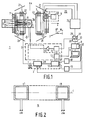
- Fig. 1 shows diagrammatically a magnetic resonance device 1 in accordance with the invention, comprising transmitter means 2 and receiver means 3 for transmitting RF electromagnetic pulses, via a transmitter coil 4, to an object 5 and for receiving magnetic resonance signals from the object 5 by means of an RF coil system 16, respectively, which magnetic resonance signals are generated, by the RF electromagnetic pulses, in the object 5 which is situated in a steady, uniform magnetic field.
- the device 1 comprises means 6 for generating the steady field.
- the means 6 comprise a main field magnet 7 and, in the case of a resistive magnet or a superconducting magnet, a DC power supply 8. In the presence of a permanent magnet, the DC power supply 8 is omitted.
- the device 1 furthermore comprises processing means 9 which are coupled to the transmitter means 2 and the receiver means 3, a process computer 10 which is coupled to the processing means 9 and the transmitter means, and display means 11 for displaying a nuclear magnetization distribution which is determined, using programmed means 12, from resonance signals received by the receiver means 3, after demodulation and signal sampling thereof (detection of resonance signals).
- the transmitter means 2 comprise an RF oscillator 13 for generating a carrier signal, a modulator 14 for amplitude and/or phase and frequency modulation of the carrier signal, and a power amplifier 15 which is coupled to the transmitter coil 4.
- the RF oscillator 13 is coupled to the processing means 9 and the modulator 14 is coupled to the process computer 10.
- excitation pulses having a frequency contents around the so-called Larmor frequency of, for example protons
- the receiver means 3 for receiving the resonance signals comprise a demodulation unit 17.
- the unit 17 may comprise a double phase-sensitive detector, the output signals of which are sampled by means of a first and a second analog-to-digital converter 18,19.
- the A/D converters 18 and 19 are coupled to the processing means 9.
- the transmitter and receiver means 2,3 may alternatively be formed by a so-called phase coherent digital transmitter/receiver.
- the device 1 furthermore comprises means 20 for generating magnetic field gradients superposed on the steady, uniform field.
- the means 20 comprise gradient magnet coils 21,22 and 23 for generating magnetic field gradients G x , G y and G z , respectively, and a power supply source which can be controlled by the process computer 10 and which comprises gradient amplifiers 24 for powering the separately activatable gradient magnet coils 21,22 and 23.
- the process computer 10 comprises digital-to-analog converters (DACs) 25,26 and 27 in order to supply the gradient power supply system 24, while supplying digital codes and under the control of the process computer 10, with analog gradient waveforms whereby the respective gradients G x , G y and G z are generated.
- DACs digital-to-analog converters
- the arrangement of the gradient magnet coils in space is such that the field direction of the magnetic field gradients coincides with the direction of the steady, uniform magnetic field and that the gradient directions extend perpendicularly to one another as denoted by three mutually perpendicular axes x, y and z in Fig. 1.
- the magnetic resonance signals wherefrom a nuclear spin distribution can be reconstructed by means of Fourier transformation are obtained by means of so-called measuring sequences.
- the RF coil system 16 is connected to the otherwise common demodulation unit 17 via a signal combination device 28, which demodulation unit may be a commercially available unit.
- the signal combination device 28 can be activated by the processing means 9, via the programmed means 12.
- Fig. 2 shows an RF coil system 16 in the form of a linear array, comprising separate coil elements c1 to cn which are coupled to n channels ch1 to chn of the signal combination device 28.
- the coil elements c1 to cn are arranged along a longitudinal axis l.
- the coil elements may partly overlap one another and no strict requirements are imposed as regards mutual decoupling.
- a substantially unlimited number of coil configurations, two-dimensional as well as three-dimensional, are feasible for a magnetic resonance device 1 in accordance with the invention.
- Fig. 3 shows an object 5 positioned relative to a linear array 16 of surface coils c1 to cn. Also shown is a system of coordinates xyz.
- the linear array 16 detects magnetic resonance signals which have been generated by means of measuring sequences, such as a known spin-warp measuring sequence, and which originate from sub-volumes of, for example a slice s1 of the object 5, the processing means 9 reconstructing partial images therefrom which are combined so as to form an ultimate image.
- the measuring gradient when a measuring gradient is chosen in the y direction, the measuring gradient will not coincide with the longitudinal direction 1 of the linear array 16, so that frequency ranges of the resonance signals measured by means of the individual coil elements c1 to cn will be coincident at least to a high degree.
- these frequency ranges are shifted so that a sum signal is formed in which the frequency ranges are separated from one another.
- the sum signal is applied to the unit 17 for further processing.
- a slice s1 extending parallel to the yz plane is shown. In accordance with the invention, however, no restrictions are imposed as regards directions of measurement relative to the RF coil system 16 and measurement can be performed in arbitrary directions by means of known measuring sequences.
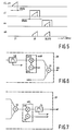
- Fig. 4 shows an embodiment of a signal combination device 28 in accordance with the invention.
- the signal combination device 28 comprises n input channels ch1 to chn which are coupled to the individual coil elements c1 to cn, respectively.
- the channels ch1 to chn comprise signal preamplifiers pal to pan which are coupled to first frequency shifting devices sh1 to shn, output signals of which are coupled, via bandpass filters fa1 to fan which may be fixed or adjustable, to a signal summing device 30 which supplies a sum signal to be further processed by the unit 17.
- the first frequency shifting devices sh1 to shn comprise mixing circuits mi1 to min which include a signal input s1 to sn for receiving signals preamplified by the signal preamplifiers pa1 to pan.
- the preamptified signals are mixed in the mixing circuits mi1 to min with respective signals from frequency-controllable oscillators la1 to lan which are applied, via oscillator inputs i1 to in, to the mixing circuits mi1 to min.
- the mixing circuits mi1 to min also comprise mixing signal outputs o1 to on for supplying mixing signals to be applied to the adjustable bandpass filters fa1 to fan.
- the bandpass filters fa1 to fan are coupled to the signal summing device 30. Control signals for the oscillators and the bandpass filters are supplied by the processing means 9 and/or the process computer 10 and are denoted by the reference cs in Fig. 1.
- Fig. 5 shows frequency shifting and combination in accordance with the invention as a function of the frequency f in MHz, on the basis of which the operation of the signal combination device 28 shown in Fig. 4 will be described.
- the description is based on the example described with reference to Fig. 3, i.e. the measuring direction is chosen so that the individual coil elements "perceive" substantially the same frequency range of the detected magnetic resonance signals, for example a frequency range of 40 kHz around an RF signal of 21 MHz; a transmission frequency of the magnetic resonance device 1, i.e. the field strength of the main field is then approximately 0.5 T, measurement being performed on protons.
- the transmission frequency is determined by the known Larmor relation, reception frequencies of the magnetic resonance signals being co-dependent in known manner on the applied gradient magnetic fields.
- the signals at the signal inputs s1 to sn of the first frequency shifting devices sh1 to shn are mixed in the mixing circuits mi1 to min so that frequency-shifted, non-overlapping signals appear at the respective outputs o1 to on of the mixing circuits mi1 to min.
- a sum signal sm is obtained in which the frequency ranges of the individual coil elements are separated from one another.
- the bandpass filters fa1 to fan are adjusted so that they are centred around frequency bands of the signals to be filtered.
- Use can alternatively be made of fixed, preadjusted bandpass filters. In the present example, central frequencies of 30 and 30.070 MHz have been adjusted.
- the mixing frequencies may then be 9 and 9.07 MHz and 51 and 51.070 MHz, respectively, depending on whether a mixing product is used in the form of a sum signal or a difference signal.
- Use can also be made of single sideband techniques.
- the bandwidth of the signals to be received is comparatively narrow, for example 10 kHz
- partial overlapping of filter bands is permissible, resulting in a smaller overall bandwidth of the sum signal.
- the overall bandwidth at least equals n times the bandwidth of one channel.
- the adjustment of the oscillators is determined on the basis of the a priori known orientation of the RF coil system 16 and the a priori known measuring sequence to be used, which means that it is known in advance which gradients will be successively switched.
- the direction and the intensity of the measuring gradient codetermines whether, and to what extent, frequency ranges of the individual coil elements will overlap.
- Fig. 6 shows a preferred embodiment of a signal combination device 28 in accordance with the invention which is identical to the device 28 shown in Fig. 4, except that in all channels ch1 to chn second frequency shifting devices ssh1 to sshn are connected between the bandpass filters fa1 to fan and the signal summing device 30.
- the second frequency shifting devices ssh1 to sshn comprise mixing circuits smi1 to smin which mix oscillator signals from frequency-controllable oscillators lb1 to lbn (only lbn is shown) with output signals of the bandpass filters fa1 to fan.
- the oscillators la1 to lan can be adjusted to frequencies which shift the frequency ranges to frequencies around 25 MHz, i.e. to frequencies around 46 MHz when a difference signal is formed as the mixing product.
- the oscillators lb1 to lbn can also be adjusted to about 46 MHz when difference signals are formed.
- the bandpass filters may be identical, enabling a simpler design.
- the output signal of the signal combination device 28 can be applied to standard hardware.
- Fig. 7 shows another embodiment of a signal combination device 28 in accordance with the invention whose construction is identical to that of the device shown in Fig. 4, except that a second frequency shifting device ssh is connected subsequent to the signal summing device 30.
- the second frequency shifting device ssh has the same construction as the first frequency shifting devices ssh 1 to sshn and comprises a mixing circuit smi and a controllable oscillator lb.
- the mixing circuit smi is coupled, at its output side, to a filter fb which ensures that undesirable mixing products are filtered out.
- the oscillators la1 to lan in this version are adjusted to approximately 9 or 51 MHz, depending on the mixing product to be formed, and the oscillator lb is adjusted to a frequency which corresponds substantially to the mean frequency of the oscillators la1 to lan. Therefore, the first frequency shifting devices sh1 to shn provide frequency separation and the second frequency shifting device ensures that the sum signal is shifted to a frequency band of commercially available standard hardware so as to be further processed.
- a magnetic resonance device comprising several signal combination devices 28 and demodulation units 17.
Landscapes
- Physics & Mathematics (AREA)
- Condensed Matter Physics & Semiconductors (AREA)
- General Physics & Mathematics (AREA)
- Engineering & Computer Science (AREA)
- Signal Processing (AREA)
- High Energy & Nuclear Physics (AREA)
- Magnetic Resonance Imaging Apparatus (AREA)
Abstract
A known magnetic resonance device (1) operates with a coil array (c1 to cn) which serves as a detection coil whereby magnetic resonance signals are detected so as to form partial images of a sub-volume of an object (5) to be measured. A signal processing unit (9) forms an overall image from the partial images. Because the known device utilizes separate detection and signal acquisition channels, it is comparatively expensive and complex. In accordance with the invention, a simpler and less expensive magnetic resonance device (1) is obtained in that the device comprises a signal combination device (28) which shifts frequency ranges (s1 to sn) of individual coil elements in the coil array in respect of frequency and which forms, from the shifted frequency ranges (o1 to on) a sum signal (sm) in which the frequency ranges are separated from one another. As a result, many common circuits can be saved, without leading to a loss of flexibility of the device (1), so that the advantages of fully separated channels are retained.
Description
- The invention relates to a magnetic resonance device, comprising a main field magnet for generating a steady magnetic field in a measuring space for accommodating an object, a coil system for generating a gradient magnetic field, and an RF coil system which consists of several coil elements for detection of magnetic resonance signals to be generated in the object.
- A magnetic resonance device of this kind is known from the international Patent Application WO 89/05115. The magnetic resonance device disclosed in the cited Patent Application is used to form partial images from magnetic resonance signals originating from separate coil elements. The partial images are combined so as to form an ultimate image of a sub-volume of the object measured by means of the RF coil system. The signals from the individual coil elements are detected in separate detection channels, are sampled and subsequently applied to processing means, completely independently from one another, in order to form the partial images and the ultimate image. The combination of the partial images so as to form an ultimate image should be executed pixel-wise in order to prevent the addition of noise. Because signal processing of the signals in the detection channels is performed in a completely independent manner, no restrictions exist as regards the orientation of the RF coil system relative to a measuring gradient field direction, i.e. given a predetermined measuring gradient field direction associated with a measuring sequence for executing a given magnetic resonance measurement, a free choice exists as regards the orientation of the RF coil system. The described magnetic resonance device, however, is comparatively expensive and complex because a separate detection channel is required for each individual coil element. Furthermore, generally speaking, several cable passages from a signal detection system arranged within a shielded measuring space of the magnetic resonance device to processing means situated outside the shielded space will be required.
- It is the object of the invention to provide a magnetic resonance device which is cheaper and simpler.
- A magnetic resonance device in accordance with the invention is characterized in that the magnetic resonance device comprises a signal combination device which is operative to shift frequency ranges of individual coil elements in respect of frequency and to combine the shifted frequency ranges so that on a sum output of the signal combination device there is formed a sum signal in which the frequency ranges are at least substantially separated from one another. Because signal combination already takes place in the RF section of the magnetic resonance device, the construction of each detection channel may be simpler. The signal shifting and combination are executed so that the advantages of a device comprising separate channels up to data processing are maintained, i.e. the orientation of the coil system relative to a measuring gradient can still be chosen completely as desired.
- It is to be noted that even though EP-A- 0 460 761, being prior art in conformity with Article 54(3) EPC, mentions signal combination, the frequency ranges of the various coil elements therein need be separated from one another as from the very start, which implies that when a linear array is used as the RF coil system, a longitudinal axis of the array is substantially coincident with a measuring gradient field direction of a measuring gradient in a measuring sequence.
- An embodiment of a magnetic resonance device in accordance with the invention is characterized in that the signal combination device for the individual coil elements comprises first frequency shifting devices which are coupled to the coil elements and outputs of which are coupled to fixed or adjustable bandpass filters which are coupled to a signal summing device for supplying the sum signal. Thus, a signal combination device is obtained which requires a minimum amount of hardware, even though it is no longer possible to use subsequently connected commercially available standard hardware because the transmission frequency in the magnetic resonance device deviates from the receiving frequency.
- This drawback is mitigated in a magnetic resonance device in accordance with the invention which is characterized in that the signal combination device for the individual coil elements comprises second frequency shifting devices which are connected so as to precede the signal summing device, or comprises one second frequency shifting device which is connected subsequent to the signal summing device. As a result, the hardware connected subsequent to the signal combination device may be standard hardware.
- A preferred embodiment of a magnetic resonance device is characterized in that in the presence of second frequency shifting devices connected so as to precede the signal summing device, the bandpass filters are adjusted to substantially the same central frequency. It is thus achieved that the design of the device is simpler; this is the case notably when use is made of fixed bandpass filters, that are commercially available.
- A further embodiment of a magnetic resonance device in accordance with the invention is characterized in that the coil elements are arranged in a linear array. The magnetic resonance device in accordance with the invention can then be advantageously used for many customary magnetic resonance examinations, such as the examination of a spine. Using a surface coil configuration as an array, high-quality low-noise images can be obtained across a comparatively wide field of view. Furthermore, the invention allows for a substantially unlimited number of two-dimensional as well as three-dimensional coil configurations.
- The invention will be described in detail hereinafter with reference to a drawing; therein:
- Fig. 1 shows diagrammatically a magnetic resonance device in accordance with the invention,
- Fig. 2 shows an RF coil system in the form of a linear array,
- Fig. 3 shows an object positioned relative to a linear array,
- Fig. 4 shows an embodiment of a signal combination device in accordance with the invention,
- Fig. 5 illustrates frequency shifting and combination in accordance with the invention,
- Fig. 6 shows a preferred embodiment of a signal combination device in accordance with the invention, and
- Fig. 7 shows a further embodiment of a signal combination device in accordance with the invention.
- Fig. 1 shows diagrammatically a
magnetic resonance device 1 in accordance with the invention, comprising transmitter means 2 and receiver means 3 for transmitting RF electromagnetic pulses, via a transmitter coil 4, to anobject 5 and for receiving magnetic resonance signals from theobject 5 by means of anRF coil system 16, respectively, which magnetic resonance signals are generated, by the RF electromagnetic pulses, in theobject 5 which is situated in a steady, uniform magnetic field. Thedevice 1 comprises means 6 for generating the steady field. The means 6 comprise amain field magnet 7 and, in the case of a resistive magnet or a superconducting magnet, a DC power supply 8. In the presence of a permanent magnet, the DC power supply 8 is omitted. During operation of thedevice 1 with theobject 5 arranged within themagnet coils 7 in ameasuring space 7A, a slight excess of nuclear spins (of nuclei having a magnetic moment) will be oriented in the same direction as the steady field in the state of equilibrium. From a macroscopic point of view this is to be considered as a magnetization M₀, being an equilibrium magnetization. Thedevice 1 furthermore comprises processing means 9 which are coupled to the transmitter means 2 and the receiver means 3, a process computer 10 which is coupled to the processing means 9 and the transmitter means, and display means 11 for displaying a nuclear magnetization distribution which is determined, using programmedmeans 12, from resonance signals received by the receiver means 3, after demodulation and signal sampling thereof (detection of resonance signals). More specifically, the transmitter means 2 comprise anRF oscillator 13 for generating a carrier signal, a modulator 14 for amplitude and/or phase and frequency modulation of the carrier signal, and apower amplifier 15 which is coupled to the transmitter coil 4. TheRF oscillator 13 is coupled to the processing means 9 and the modulator 14 is coupled to the process computer 10. When excitation pulses having a frequency contents around the so-called Larmor frequency of, for example protons, are applied to theobject 5 under the control of the programmedmeans 12 and via the transmitter means 2, there will be produced magnetic resonance signals wherefrom a proton nuclear spin distribution or a magnetic resonance image can be determined by the programmedmeans 12 utilizing, for example Fourier transformation. The receiver means 3 for receiving the resonance signals comprise ademodulation unit 17. Theunit 17 may comprise a double phase-sensitive detector, the output signals of which are sampled by means of a first and a second analog-to-digital converter D converters device 1 furthermore comprises means 20 for generating magnetic field gradients superposed on the steady, uniform field. Themeans 20 comprisegradient magnet coils gradient amplifiers 24 for powering the separately activatablegradient magnet coils power supply system 24, while supplying digital codes and under the control of the process computer 10, with analog gradient waveforms whereby the respective gradients Gx, Gy and Gz are generated. In the embodiment shown, the arrangement of the gradient magnet coils in space is such that the field direction of the magnetic field gradients coincides with the direction of the steady, uniform magnetic field and that the gradient directions extend perpendicularly to one another as denoted by three mutually perpendicular axes x, y and z in Fig. 1. The magnetic resonance signals wherefrom a nuclear spin distribution can be reconstructed by means of Fourier transformation are obtained by means of so-called measuring sequences. In accordance with the invention, theRF coil system 16 is connected to the otherwisecommon demodulation unit 17 via asignal combination device 28, which demodulation unit may be a commercially available unit. Thesignal combination device 28 can be activated by the processing means 9, via the programmedmeans 12. - Fig. 2 shows an
RF coil system 16 in the form of a linear array, comprising separate coil elements c1 to cn which are coupled to n channels ch1 to chn of thesignal combination device 28. The coil elements c1 to cn are arranged along a longitudinal axis l. The coil elements may partly overlap one another and no strict requirements are imposed as regards mutual decoupling. Besides the coil configuration shown, a substantially unlimited number of coil configurations, two-dimensional as well as three-dimensional, are feasible for amagnetic resonance device 1 in accordance with the invention. - Fig. 3 shows an
object 5 positioned relative to alinear array 16 of surface coils c1 to cn. Also shown is a system of coordinates xyz. In accordance with the invention, thelinear array 16 detects magnetic resonance signals which have been generated by means of measuring sequences, such as a known spin-warp measuring sequence, and which originate from sub-volumes of, for example a slice s1 of theobject 5, the processing means 9 reconstructing partial images therefrom which are combined so as to form an ultimate image. In the present example, when a measuring gradient is chosen in the y direction, the measuring gradient will not coincide with thelongitudinal direction 1 of thelinear array 16, so that frequency ranges of the resonance signals measured by means of the individual coil elements c1 to cn will be coincident at least to a high degree. Using thesignal combination device 28 in accordance with the invention, these frequency ranges are shifted so that a sum signal is formed in which the frequency ranges are separated from one another. The sum signal is applied to theunit 17 for further processing. In the present example, a slice s1 extending parallel to the yz plane is shown. In accordance with the invention, however, no restrictions are imposed as regards directions of measurement relative to theRF coil system 16 and measurement can be performed in arbitrary directions by means of known measuring sequences. - Fig. 4 shows an embodiment of a
signal combination device 28 in accordance with the invention. Thesignal combination device 28 comprises n input channels ch1 to chn which are coupled to the individual coil elements c1 to cn, respectively. The channels ch1 to chn comprise signal preamplifiers pal to pan which are coupled to first frequency shifting devices sh1 to shn, output signals of which are coupled, via bandpass filters fa1 to fan which may be fixed or adjustable, to asignal summing device 30 which supplies a sum signal to be further processed by theunit 17. The first frequency shifting devices sh1 to shn comprise mixing circuits mi1 to min which include a signal input s1 to sn for receiving signals preamplified by the signal preamplifiers pa1 to pan. The preamptified signals are mixed in the mixing circuits mi1 to min with respective signals from frequency-controllable oscillators la1 to lan which are applied, via oscillator inputs i1 to in, to the mixing circuits mi1 to min. The mixing circuits mi1 to min also comprise mixing signal outputs o1 to on for supplying mixing signals to be applied to the adjustable bandpass filters fa1 to fan. The bandpass filters fa1 to fan are coupled to thesignal summing device 30. Control signals for the oscillators and the bandpass filters are supplied by the processing means 9 and/or the process computer 10 and are denoted by the reference cs in Fig. 1. - Fig. 5 shows frequency shifting and combination in accordance with the invention as a function of the frequency f in MHz, on the basis of which the operation of the
signal combination device 28 shown in Fig. 4 will be described. The description is based on the example described with reference to Fig. 3, i.e. the measuring direction is chosen so that the individual coil elements "perceive" substantially the same frequency range of the detected magnetic resonance signals, for example a frequency range of 40 kHz around an RF signal of 21 MHz; a transmission frequency of themagnetic resonance device 1, i.e. the field strength of the main field is then approximately 0.5 T, measurement being performed on protons. For a given field strength B₀ the transmission frequency is determined by the known Larmor relation, reception frequencies of the magnetic resonance signals being co-dependent in known manner on the applied gradient magnetic fields. The signals at the signal inputs s1 to sn of the first frequency shifting devices sh1 to shn are mixed in the mixing circuits mi1 to min so that frequency-shifted, non-overlapping signals appear at the respective outputs o1 to on of the mixing circuits mi1 to min. The frequency-shifted signals are applied to the bandpass filters fa1 to fan which have a bandwidth of, for example 60 kHz. In the example shown, it has been assumed for the sake of simplicity that n = 2. After filtering and summing, a sum signal sm is obtained in which the frequency ranges of the individual coil elements are separated from one another. The bandpass filters fa1 to fan are adjusted so that they are centred around frequency bands of the signals to be filtered. Use can alternatively be made of fixed, preadjusted bandpass filters. In the present example, central frequencies of 30 and 30.070 MHz have been adjusted. The mixing frequencies may then be 9 and 9.07 MHz and 51 and 51.070 MHz, respectively, depending on whether a mixing product is used in the form of a sum signal or a difference signal. Use can also be made of single sideband techniques. If it is known a priori that the bandwidth of the signals to be received is comparatively narrow, for example 10 kHz, partial overlapping of filter bands is permissible, resulting in a smaller overall bandwidth of the sum signal. Without overlapping, the overall bandwidth at least equals n times the bandwidth of one channel. When mutual coupling of the individual coil elements is involved, appropriate correction can be performed in the processing means 9. The bandpass filters suppress noise signals outside the relevant frequency ranges, so that these noise signals will be present in irrelevant frequency ranges of other channels, resulting in an as high as possible overall signal-to-noise ratio. In the event that theobject 5 produces a signal having a bandwidth which is greater than that of the relevant signal (the field of view of the area of interest is smaller than the dimension of theobject 5 in the direction of the measuring gradient), undesirable parts of the magnetic resonance signal will also be suppressed. In the absence of suppression of undesirable magnetic resonance signals, image artefacts will occur in neighbouring channels. Generally speaking, the adjustment of the oscillators is determined on the basis of the a priori known orientation of theRF coil system 16 and the a priori known measuring sequence to be used, which means that it is known in advance which gradients will be successively switched. The direction and the intensity of the measuring gradient codetermines whether, and to what extent, frequency ranges of the individual coil elements will overlap. - Fig. 6 shows a preferred embodiment of a
signal combination device 28 in accordance with the invention which is identical to thedevice 28 shown in Fig. 4, except that in all channels ch1 to chn second frequency shifting devices ssh1 to sshn are connected between the bandpass filters fa1 to fan and thesignal summing device 30. The second frequency shifting devices ssh1 to sshn, only the frequency shifting device ssh1 being shown, comprise mixing circuits smi1 to smin which mix oscillator signals from frequency-controllable oscillators lb1 to lbn (only lbn is shown) with output signals of the bandpass filters fa1 to fan. In this version, for input frequency ranges around 21 MHz, the oscillators la1 to lan can be adjusted to frequencies which shift the frequency ranges to frequencies around 25 MHz, i.e. to frequencies around 46 MHz when a difference signal is formed as the mixing product. The oscillators lb1 to lbn can also be adjusted to about 46 MHz when difference signals are formed. In this version the bandpass filters may be identical, enabling a simpler design. The output signal of thesignal combination device 28 can be applied to standard hardware. - Fig. 7 shows another embodiment of a
signal combination device 28 in accordance with the invention whose construction is identical to that of the device shown in Fig. 4, except that a second frequency shifting device ssh is connected subsequent to thesignal summing device 30. The second frequency shifting device ssh has the same construction as the first frequencyshifting devices ssh 1 to sshn and comprises a mixing circuit smi and a controllable oscillator lb. The mixing circuit smi is coupled, at its output side, to a filter fb which ensures that undesirable mixing products are filtered out. For input frequency ranges around 21 MHz, the oscillators la1 to lan in this version are adjusted to approximately 9 or 51 MHz, depending on the mixing product to be formed, and the oscillator lb is adjusted to a frequency which corresponds substantially to the mean frequency of the oscillators la1 to lan. Therefore, the first frequency shifting devices sh1 to shn provide frequency separation and the second frequency shifting device ensures that the sum signal is shifted to a frequency band of commercially available standard hardware so as to be further processed. - Within the scope of the present invention it is also possible to provide a magnetic resonance device comprising several
signal combination devices 28 anddemodulation units 17.
Claims (9)
- A magnetic resonance device (1), comprising a main field magnet (7) for generating a steady magnetic field in a measuring space (7A) for accommodating an object (5), a coil system (21, 22, 23) for generating a gradient magnetic field, and an RF coil system (16) which consists of several coil elements (c1 to cn) for detection of magnetic resonance signals to be generated in the object (5), characterized in that the magnetic resonance device (1) comprises a signal combination device (28) which is operative to shift frequency ranges (s1 to sn) of individual coil elements (c1 to cn) in respect of frequency and to combine the shifted frequency ranges (o1 to on) so that on a sum output (sm) of the signal combination device (28) there is formed a sum signal (sm) in which the frequency ranges are at least substantially separated from one another.
- A magnetic resonance device (1) as claimed in Claim 1, characterized in that the signal combination device (28) for the individual coil elements (c1 to cn), comprises first frequency shifting devices (sh1 to shn) which are coupled to the coil elements and outputs of which are coupled to fixed or adjustable bandpass filters (fa1 to fan) which are coupled to a signal summing device (30) for supplying the sum signal (sm).
- A magnetic resonance device (1) as claimed in Claim 2, characterized in that the signal combination device (28) for the individual coil elements (c1 to cn) comprises second frequency shifting devices (ssh1 to sshn) which are connected so as to precede the signal summing device (30), or comprises one second frequency shifting device (ssh) which is connected subsequent to the signal summing device.
- A magnetic resonance device (1) as claimed in Claim 2 or 3, characterized in that the frequency shifting devices (sh1 to shn) comprise mixing circuits (mi1 to min) which comprise a signal input (s1 to sn) for receiving a signal to be mixed, an oscillator input (i1 to in) which is coupled to a frequency-controllable oscillator (la1 to lan), and a mixing signal output (o1 to on) for supplying a mixing signal.
- A magnetic resonance device (1) as claimed in Claim 2 or 3, characterized in that in the presence of second frequency shifting devices (ssh1 to sshn) connected so as to precede the signal summing device, the band filters (fa1 to fan) are adjusted to substantially the same central frequency.
- A magnetic resonance device (1) as claimed in any one of the preceding Claims, characterized in that the coil elements (c1 to cn) are arranged in a linear array.
- A magnetic resonance device (1) as claimed in any one of the preceding Claims, characterized in that a signal preamplifier (pa1 to pan) is connected between the individual coil elements (c1 to cn) and the first frequency shifting devices (sh1 to shn).
- A magnetic resonance device as claimed in any one of the preceding Claims, characterized in that it comprises more than one signal combination device (28) and more than one receiver.
- A signal combination device (28) which is suitable for use in a magnetic resonance device (1) as claimed in any one of the preceding Claims.
Applications Claiming Priority (2)
| Application Number | Priority Date | Filing Date | Title |
|---|---|---|---|
| EP91203132 | 1991-11-29 | ||
| EP91203132 | 1991-11-29 |
Publications (1)
| Publication Number | Publication Date |
|---|---|
| EP0554584A1 true EP0554584A1 (en) | 1993-08-11 |
Family
ID=8208044
Family Applications (1)
| Application Number | Title | Priority Date | Filing Date |
|---|---|---|---|
| EP92203603A Withdrawn EP0554584A1 (en) | 1991-11-29 | 1992-11-23 | Magnetic resonance device and signal combination device |
Country Status (3)
| Country | Link |
|---|---|
| US (1) | US5319309A (en) |
| EP (1) | EP0554584A1 (en) |
| JP (1) | JPH05269111A (en) |
Cited By (13)
| Publication number | Priority date | Publication date | Assignee | Title |
|---|---|---|---|---|
| EP0691578A2 (en) | 1994-03-22 | 1996-01-10 | Agfa-Gevaert N.V. | Imaging element and method for making a printing plate according to the silver salt diffusion transfer process |
| EP1398642A2 (en) * | 2002-09-12 | 2004-03-17 | General Electric Company | Extended volume imaging using MRI with parallel reception |
| GB2374151B (en) * | 1999-12-15 | 2004-12-15 | Halliburton Energy Serv Inc | Method and apparatus for improving the vertical resolution of NMR logs |
| GB2403553A (en) * | 1999-12-15 | 2005-01-05 | Halliburton Energy Serv Inc | Improving vertical resolution of NMR logs |
| WO2006075214A2 (en) * | 2004-12-06 | 2006-07-20 | Koninklijke Philips Electronics N.V. | Frequency domain multiplexed transmission of mr signals from a receiver coil array |
| EP1774366A2 (en) * | 2004-06-14 | 2007-04-18 | Doron Kwiat | A magnetic resonance imaging method and device using a static and homogeneous magnetic field |
| WO2009070717A1 (en) * | 2007-11-27 | 2009-06-04 | Kim Jae K | Noise reduction by means of spectral parallelism |
| CN1735814B (en) * | 2003-01-07 | 2010-06-16 | 皇家飞利浦电子股份有限公司 | High-frequency system for an MR apparatus with multiple transmit channels and the MR apparatus therein |
| CN102200569A (en) * | 2010-03-23 | 2011-09-28 | 西门子公司 | Transmission method for magnetic resonance signal with dual frequency conversion |
| US20130134980A1 (en) * | 2011-11-30 | 2013-05-30 | Markus Vester | Receiving Method, Receiving System for Magnetic Resonance Signals, and Magnetic Resonance Imaging System |
| DE102012211312A1 (en) * | 2012-06-29 | 2014-01-02 | Siemens Aktiengesellschaft | Method for the simultaneous transmission of at least two high-frequency transmission signals via a common high-frequency line, signal transmission device and magnetic resonance tomograph |
| WO2014024114A1 (en) * | 2012-08-06 | 2014-02-13 | Insiava (Pty) Ltd. | A data transfer circuit, method and system for an mri machine having a plurality of receiver surface coils |
| US10495705B2 (en) | 2015-07-15 | 2019-12-03 | Koninklijke Philips N.V. | RF transmit module with a local field monitoring unit for a magnetic resonance examination system |
Families Citing this family (9)
| Publication number | Priority date | Publication date | Assignee | Title |
|---|---|---|---|---|
| US5759152A (en) * | 1996-10-02 | 1998-06-02 | Mayo Foundation For Medical Education And Research | Phase-aligned NMR surface coil image reconstruction |
| WO1999012049A1 (en) * | 1997-08-28 | 1999-03-11 | Koninklijke Philips Electronics N.V. | Correction of magnetic resonance signals in magnetic resonance imaging |
| JP2003517911A (en) * | 1999-12-20 | 2003-06-03 | コーニンクレッカ フィリップス エレクトロニクス エヌ ヴィ | MRI system with free tilt control |
| DE10148462C1 (en) * | 2001-10-01 | 2003-06-18 | Siemens Ag | Transmission method for an analog magnetic resonance signal and devices corresponding to it |
| DE10148445A1 (en) * | 2001-10-01 | 2003-04-30 | Siemens Ag | Signal evaluation method for magnetic resonance received signals and the corresponding receiving arrangement |
| DE102008023467B4 (en) * | 2008-05-14 | 2012-06-14 | Siemens Aktiengesellschaft | Arrangement for transmitting magnetic resonance signals |
| US8244192B2 (en) * | 2009-11-25 | 2012-08-14 | General Electric Company | System and method for wireless communication of magnetic resonance data |
| WO2013118117A1 (en) * | 2012-02-08 | 2013-08-15 | Anatech Advanced Nmr Algorithms Technologies Ltd | Method and system for inspection of composite material components |
| US10393834B2 (en) * | 2014-01-27 | 2019-08-27 | Hitachi, Ltd. | Magnetic resonance imaging apparatus and noise reduction method |
Citations (6)
| Publication number | Priority date | Publication date | Assignee | Title |
|---|---|---|---|---|
| EP0112663A2 (en) * | 1982-12-17 | 1984-07-04 | Picker International Limited | Nuclear magnetic resonance methods and apparatus |
| US4737713A (en) * | 1986-11-26 | 1988-04-12 | Fonar Corporation | Apparatus and method for processing an electrical signal and increasing a signal-to-noise ratio thereof |
| EP0411840A2 (en) * | 1989-08-04 | 1991-02-06 | General Electric Company | Radio frequency receiver for a NMR instrument |
| DE4037294A1 (en) * | 1989-11-30 | 1991-07-25 | Elscint Ltd | RECEIVER SWITCHING ARRANGEMENT WITH A GROUP OF SURFACE COILS |
| EP0460761A1 (en) * | 1990-06-08 | 1991-12-11 | Koninklijke Philips Electronics N.V. | RF coil system in a magnetic resonance imaging apparatus |
| EP0467378A2 (en) * | 1990-07-18 | 1992-01-22 | Kabushiki Kaisha Toshiba | Multiple coil type magnetic resonance imaging system including filters with different passbands |
Family Cites Families (5)
| Publication number | Priority date | Publication date | Assignee | Title |
|---|---|---|---|---|
| US4577152A (en) * | 1983-04-11 | 1986-03-18 | Albert Macovski | Selective material projection imaging system using nuclear magnetic resonance |
| US4665366A (en) * | 1985-03-11 | 1987-05-12 | Albert Macovski | NMR imaging system using phase-shifted signals |
| DE3739856A1 (en) * | 1987-11-25 | 1989-06-08 | Philips Patentverwaltung | NUCLEAR RESONANCE SPECTROSCOPY METHOD |
| US4825162A (en) * | 1987-12-07 | 1989-04-25 | General Electric Company | Nuclear magnetic resonance (NMR) imaging with multiple surface coils |
| DE3853356T2 (en) * | 1987-12-07 | 1995-10-26 | Gen Electric | Magnetic nuclear magnetic resonance (NMR) imaging with multiple surface coils. |
-
1992
- 1992-11-23 EP EP92203603A patent/EP0554584A1/en not_active Withdrawn
- 1992-11-25 US US07/981,703 patent/US5319309A/en not_active Expired - Fee Related
- 1992-11-26 JP JP4317189A patent/JPH05269111A/en active Pending
Patent Citations (6)
| Publication number | Priority date | Publication date | Assignee | Title |
|---|---|---|---|---|
| EP0112663A2 (en) * | 1982-12-17 | 1984-07-04 | Picker International Limited | Nuclear magnetic resonance methods and apparatus |
| US4737713A (en) * | 1986-11-26 | 1988-04-12 | Fonar Corporation | Apparatus and method for processing an electrical signal and increasing a signal-to-noise ratio thereof |
| EP0411840A2 (en) * | 1989-08-04 | 1991-02-06 | General Electric Company | Radio frequency receiver for a NMR instrument |
| DE4037294A1 (en) * | 1989-11-30 | 1991-07-25 | Elscint Ltd | RECEIVER SWITCHING ARRANGEMENT WITH A GROUP OF SURFACE COILS |
| EP0460761A1 (en) * | 1990-06-08 | 1991-12-11 | Koninklijke Philips Electronics N.V. | RF coil system in a magnetic resonance imaging apparatus |
| EP0467378A2 (en) * | 1990-07-18 | 1992-01-22 | Kabushiki Kaisha Toshiba | Multiple coil type magnetic resonance imaging system including filters with different passbands |
Cited By (26)
| Publication number | Priority date | Publication date | Assignee | Title |
|---|---|---|---|---|
| EP0691578A2 (en) | 1994-03-22 | 1996-01-10 | Agfa-Gevaert N.V. | Imaging element and method for making a printing plate according to the silver salt diffusion transfer process |
| GB2374151B (en) * | 1999-12-15 | 2004-12-15 | Halliburton Energy Serv Inc | Method and apparatus for improving the vertical resolution of NMR logs |
| GB2403553A (en) * | 1999-12-15 | 2005-01-05 | Halliburton Energy Serv Inc | Improving vertical resolution of NMR logs |
| GB2403553B (en) * | 1999-12-15 | 2005-03-02 | Halliburton Energy Serv Inc | Method and apparatus for improving the vertical resolution of NMR logs |
| EP1398642A2 (en) * | 2002-09-12 | 2004-03-17 | General Electric Company | Extended volume imaging using MRI with parallel reception |
| EP1398642A3 (en) * | 2002-09-12 | 2004-06-30 | General Electric Company | Extended volume imaging using MRI with parallel reception |
| US7009396B2 (en) | 2002-09-12 | 2006-03-07 | General Electric Company | Method and system for extended volume imaging using MRI with parallel reception |
| CN1735814B (en) * | 2003-01-07 | 2010-06-16 | 皇家飞利浦电子股份有限公司 | High-frequency system for an MR apparatus with multiple transmit channels and the MR apparatus therein |
| EP1774366A4 (en) * | 2004-06-14 | 2007-11-14 | Doron Kwiat | A magnetic resonance imaging method and device using a static and homogeneous magnetic field |
| EP1774366A2 (en) * | 2004-06-14 | 2007-04-18 | Doron Kwiat | A magnetic resonance imaging method and device using a static and homogeneous magnetic field |
| US7701220B2 (en) | 2004-12-06 | 2010-04-20 | Koninklijke Philips Electronics N. V. | Methods and apparatuses for connecting receive coils in magnetic resonance imaging scanners |
| WO2006075214A3 (en) * | 2004-12-06 | 2006-11-02 | Koninkl Philips Electronics Nv | Frequency domain multiplexed transmission of mr signals from a receiver coil array |
| WO2006075214A2 (en) * | 2004-12-06 | 2006-07-20 | Koninklijke Philips Electronics N.V. | Frequency domain multiplexed transmission of mr signals from a receiver coil array |
| US8232799B2 (en) | 2007-11-27 | 2012-07-31 | Arjae Spectral Enterprises | Noise reduction apparatus, systems, and methods |
| WO2009070717A1 (en) * | 2007-11-27 | 2009-06-04 | Kim Jae K | Noise reduction by means of spectral parallelism |
| DE102010012395B4 (en) * | 2010-03-23 | 2014-04-30 | Siemens Aktiengesellschaft | Transmission method for magnetic resonance signals with dual frequency conversion |
| CN102200569A (en) * | 2010-03-23 | 2011-09-28 | 西门子公司 | Transmission method for magnetic resonance signal with dual frequency conversion |
| DE102010012395A1 (en) * | 2010-03-23 | 2011-09-29 | Siemens Aktiengesellschaft | Method for transmitting magnetic resonance signals into local coil, involves filtering output signals of rear frequency mixer in frequency filter, where output signals of rear frequency mixer are associated transferred to common signal |
| US8489025B2 (en) | 2010-03-23 | 2013-07-16 | Siemens Aktiengesellschaft | Method for transmitting magnetic resonance signals with double frequency conversion |
| CN102200569B (en) * | 2010-03-23 | 2015-07-22 | 西门子公司 | Transmission method for magnetic resonance signal with dual frequency conversion |
| US20130134980A1 (en) * | 2011-11-30 | 2013-05-30 | Markus Vester | Receiving Method, Receiving System for Magnetic Resonance Signals, and Magnetic Resonance Imaging System |
| US9465092B2 (en) * | 2011-11-30 | 2016-10-11 | Siemens Aktiengesellschaft | Receiving method, receiving system for magnetic resonance signals, and magnetic resonance imaging system |
| DE102012211312A1 (en) * | 2012-06-29 | 2014-01-02 | Siemens Aktiengesellschaft | Method for the simultaneous transmission of at least two high-frequency transmission signals via a common high-frequency line, signal transmission device and magnetic resonance tomograph |
| US9778330B2 (en) | 2012-06-29 | 2017-10-03 | Siemens Aktiengesellschaft | Method for simultaneous transmission of high-frequency transmission signals via a common high-frequency line |
| WO2014024114A1 (en) * | 2012-08-06 | 2014-02-13 | Insiava (Pty) Ltd. | A data transfer circuit, method and system for an mri machine having a plurality of receiver surface coils |
| US10495705B2 (en) | 2015-07-15 | 2019-12-03 | Koninklijke Philips N.V. | RF transmit module with a local field monitoring unit for a magnetic resonance examination system |
Also Published As
| Publication number | Publication date |
|---|---|
| US5319309A (en) | 1994-06-07 |
| JPH05269111A (en) | 1993-10-19 |
Similar Documents
| Publication | Publication Date | Title |
|---|---|---|
| US5319309A (en) | Magnetic resonance device and signal combination device | |
| US7701220B2 (en) | Methods and apparatuses for connecting receive coils in magnetic resonance imaging scanners | |
| EP1810047B1 (en) | Rf receive coil assembly with individual digitizers and means for synchronization thereof | |
| EP0412747B1 (en) | Magnetic resonance systems | |
| US20060054810A1 (en) | High-frequency system for an mr apparatus with multiple transmit channels | |
| US5636636A (en) | Magnetic resonance method for imaging a moving object and device for carrying out the method | |
| US20080265890A1 (en) | Simultaneous Mr-Excitation of Multiple Nuclei with a Single Rf Amplifier | |
| US20120068704A1 (en) | Magnetic resonance method and system to generate mr image data with parallel slice excitation | |
| US7449886B2 (en) | MR receiver assembly having readout cables capable of multiple channel transmissions | |
| IL92510A (en) | Surface coil array receiver | |
| EP0293085B1 (en) | Magnetic resonance imaging apparatus | |
| EP0368401B1 (en) | Magnetic resonance method and device | |
| US7378844B2 (en) | Magnetic resonance system, receiver & method of generating detecting and digitizing analog MR signals solely within the MR shielded environment | |
| US5442292A (en) | Nuclear magnetic resonance apparatus having at least two transmission frequencies | |
| US4952876A (en) | Variable bandwidth multiecho NMR imaging | |
| Sporrer et al. | Integrated CMOS receiver for wearable coil arrays in MRI applications | |
| US7816916B2 (en) | Magnetic resonance imaging method using a parallel imaging technique combined with a zoomed acquisition technique | |
| US7173427B1 (en) | Magnetic resonance imaging apparatus and magnetic resonance imaging method | |
| JP2503821B2 (en) | NMR signal processing method and apparatus | |
| CA2212615A1 (en) | Suppression of radiation damping in nmr | |
| US10459049B2 (en) | Magnetic resonance imaging apparatus | |
| JP2555233B2 (en) | Nuclear magnetic resonance equipment | |
| US20240133988A1 (en) | Sensing motion in mri using rf intermodulation | |
| US11143724B2 (en) | Receiving device for frequency-multiplexed signals | |
| US20240329170A1 (en) | Transmit device for generating a multi-frequency pilot tone and magnetic resonance tomograph with transmit device |
Legal Events
| Date | Code | Title | Description |
|---|---|---|---|
| PUAI | Public reference made under article 153(3) epc to a published international application that has entered the european phase |
Free format text: ORIGINAL CODE: 0009012 |
|
| AK | Designated contracting states |
Kind code of ref document: A1 Designated state(s): DE FR GB IT NL |
|
| 17P | Request for examination filed |
Effective date: 19940204 |
|
| STAA | Information on the status of an ep patent application or granted ep patent |
Free format text: STATUS: THE APPLICATION HAS BEEN WITHDRAWN |
|
| 18W | Application withdrawn |
Withdrawal date: 19960424 |