WO2015105185A1 - Dispositif d'assèchement d'air comprimé - Google Patents
Dispositif d'assèchement d'air comprimé Download PDFInfo
- Publication number
- WO2015105185A1 WO2015105185A1 PCT/JP2015/050515 JP2015050515W WO2015105185A1 WO 2015105185 A1 WO2015105185 A1 WO 2015105185A1 JP 2015050515 W JP2015050515 W JP 2015050515W WO 2015105185 A1 WO2015105185 A1 WO 2015105185A1
- Authority
- WO
- WIPO (PCT)
- Prior art keywords
- compressed air
- glass fiber
- oil
- fiber filter
- desiccant
- Prior art date
Links
Images


Classifications
-
- B—PERFORMING OPERATIONS; TRANSPORTING
- B01—PHYSICAL OR CHEMICAL PROCESSES OR APPARATUS IN GENERAL
- B01D—SEPARATION
- B01D53/00—Separation of gases or vapours; Recovering vapours of volatile solvents from gases; Chemical or biological purification of waste gases, e.g. engine exhaust gases, smoke, fumes, flue gases, aerosols
- B01D53/26—Drying gases or vapours
- B01D53/261—Drying gases or vapours by adsorption
-
- B—PERFORMING OPERATIONS; TRANSPORTING
- B01—PHYSICAL OR CHEMICAL PROCESSES OR APPARATUS IN GENERAL
- B01D—SEPARATION
- B01D53/00—Separation of gases or vapours; Recovering vapours of volatile solvents from gases; Chemical or biological purification of waste gases, e.g. engine exhaust gases, smoke, fumes, flue gases, aerosols
- B01D53/02—Separation of gases or vapours; Recovering vapours of volatile solvents from gases; Chemical or biological purification of waste gases, e.g. engine exhaust gases, smoke, fumes, flue gases, aerosols by adsorption, e.g. preparative gas chromatography
- B01D53/04—Separation of gases or vapours; Recovering vapours of volatile solvents from gases; Chemical or biological purification of waste gases, e.g. engine exhaust gases, smoke, fumes, flue gases, aerosols by adsorption, e.g. preparative gas chromatography with stationary adsorbents
- B01D53/0407—Constructional details of adsorbing systems
- B01D53/0415—Beds in cartridges
-
- B—PERFORMING OPERATIONS; TRANSPORTING
- B03—SEPARATION OF SOLID MATERIALS USING LIQUIDS OR USING PNEUMATIC TABLES OR JIGS; MAGNETIC OR ELECTROSTATIC SEPARATION OF SOLID MATERIALS FROM SOLID MATERIALS OR FLUIDS; SEPARATION BY HIGH-VOLTAGE ELECTRIC FIELDS
- B03C—MAGNETIC OR ELECTROSTATIC SEPARATION OF SOLID MATERIALS FROM SOLID MATERIALS OR FLUIDS; SEPARATION BY HIGH-VOLTAGE ELECTRIC FIELDS
- B03C3/00—Separating dispersed particles from gases or vapour, e.g. air, by electrostatic effect
- B03C3/01—Pretreatment of the gases prior to electrostatic precipitation
- B03C3/011—Prefiltering; Flow controlling
-
- B—PERFORMING OPERATIONS; TRANSPORTING
- B03—SEPARATION OF SOLID MATERIALS USING LIQUIDS OR USING PNEUMATIC TABLES OR JIGS; MAGNETIC OR ELECTROSTATIC SEPARATION OF SOLID MATERIALS FROM SOLID MATERIALS OR FLUIDS; SEPARATION BY HIGH-VOLTAGE ELECTRIC FIELDS
- B03C—MAGNETIC OR ELECTROSTATIC SEPARATION OF SOLID MATERIALS FROM SOLID MATERIALS OR FLUIDS; SEPARATION BY HIGH-VOLTAGE ELECTRIC FIELDS
- B03C3/00—Separating dispersed particles from gases or vapour, e.g. air, by electrostatic effect
- B03C3/019—Post-treatment of gases
-
- B—PERFORMING OPERATIONS; TRANSPORTING
- B03—SEPARATION OF SOLID MATERIALS USING LIQUIDS OR USING PNEUMATIC TABLES OR JIGS; MAGNETIC OR ELECTROSTATIC SEPARATION OF SOLID MATERIALS FROM SOLID MATERIALS OR FLUIDS; SEPARATION BY HIGH-VOLTAGE ELECTRIC FIELDS
- B03C—MAGNETIC OR ELECTROSTATIC SEPARATION OF SOLID MATERIALS FROM SOLID MATERIALS OR FLUIDS; SEPARATION BY HIGH-VOLTAGE ELECTRIC FIELDS
- B03C3/00—Separating dispersed particles from gases or vapour, e.g. air, by electrostatic effect
- B03C3/28—Plant or installations without electricity supply, e.g. using electrets
-
- F—MECHANICAL ENGINEERING; LIGHTING; HEATING; WEAPONS; BLASTING
- F04—POSITIVE - DISPLACEMENT MACHINES FOR LIQUIDS; PUMPS FOR LIQUIDS OR ELASTIC FLUIDS
- F04B—POSITIVE-DISPLACEMENT MACHINES FOR LIQUIDS; PUMPS
- F04B39/00—Component parts, details, or accessories, of pumps or pumping systems specially adapted for elastic fluids, not otherwise provided for in, or of interest apart from, groups F04B25/00 - F04B37/00
- F04B39/16—Filtration; Moisture separation
-
- B—PERFORMING OPERATIONS; TRANSPORTING
- B01—PHYSICAL OR CHEMICAL PROCESSES OR APPARATUS IN GENERAL
- B01D—SEPARATION
- B01D2257/00—Components to be removed
- B01D2257/70—Organic compounds not provided for in groups B01D2257/00 - B01D2257/602
- B01D2257/702—Hydrocarbons
-
- B—PERFORMING OPERATIONS; TRANSPORTING
- B01—PHYSICAL OR CHEMICAL PROCESSES OR APPARATUS IN GENERAL
- B01D—SEPARATION
- B01D2257/00—Components to be removed
- B01D2257/80—Water
-
- B—PERFORMING OPERATIONS; TRANSPORTING
- B01—PHYSICAL OR CHEMICAL PROCESSES OR APPARATUS IN GENERAL
- B01D—SEPARATION
- B01D2258/00—Sources of waste gases
- B01D2258/06—Polluted air
Definitions
- the present invention relates to a compressed air drying apparatus for drying compressed air supplied from a compressor.
- Vehicles such as trucks, buses and construction machinery control systems such as brakes and suspensions using compressed air sent from a compressor directly connected to an internal combustion engine (hereinafter referred to as an engine).
- This compressed air contains moisture contained in the atmosphere and oil that lubricates the inside of the compressor.
- rust is generated and a rubber member (such as an O-ring) swells, causing malfunction.
- moisture content and oil content from compressed air is provided downstream of the compressor of an air system
- the compressed air drying device includes a support base, a drying container filled with a desiccant, and an outer case that covers the drying container and is attached to the support base.
- the support base is provided with an inlet through which compressed air supplied from the compressor flows, an outlet through which compressed dry air is discharged, and a drain discharge port including a drain discharge device (see, for example, Patent Document 1). .
- the compressed air drying device discharges the compressed dry air from the outlet to the external air tank while allowing the compressed air flowing from the inlet to pass through the drying container and storing the compressed dry air in the outer case during the load operation to remove moisture.
- the compressed air drying device is a container for drying the compressed dry air accumulated in the outer case by opening the drain valve of the drain discharge device during the unload operation for regenerating the desiccant in the direction opposite to that during the load operation. To drain water from the drain valve. The compressed air drying device repeats this loading operation and unloading operation.
- a filter element for removing oil contained in the compressed air is provided in addition to the drying container.
- the filter element is made of, for example, a nonwoven fabric.
- the conventional filter element can only capture oil particles having a relatively large particle diameter, not a little oil remains in the compressed air that has passed through the desiccant and the filter element. For this reason, improvement of the removal rate of the oil contained in compressed air is desired.
- An object of the present invention is to provide a compressed air drying apparatus capable of improving the removal rate of oil contained in compressed air.
- a compressed air drying apparatus that solves the above problems is filled with a drying base, a support base having an inlet for compressed air from a compressor, an outlet for compressed air, and an oil / water outlet provided with a drain valve device.
- a drying container mounted on the support base, and the compressed air flowing in from the inlet is dried by the desiccant during the load operation, and the dried compressed air is discharged from the outlet, and the compressed air is discharged during the unload operation.
- glass fiber is provided on at least one of the upstream side and the downstream side with respect to the desiccant in the flow of the compressed air during the load operation.
- oil particles having a relatively small particle size can be captured by providing a glass fiber filter on at least one of the upstream side and the downstream side with respect to the desiccant. For this reason, the oil removal rate of compressed air can be improved, removing a water
- this compressed air drying apparatus it is preferable to provide a collision material in which the compressed air removes oil when oil particles collide in the flow path of the compressed air.
- oil particles having a relatively large particle size are captured by the impact material upstream of the glass fiber filter.
- the oil particles having a smaller diameter than the oil particles captured by the impact material are captured by the glass fiber filter, the oil removal rate of the compressed dry air can be increased.
- an oil adsorbing material that captures oil particles by electrostatic force is preferably provided in the flow path of the compressed air.
- oil particles having a relatively large particle size are captured by the oil adsorbing material upstream of the glass fiber filter.
- the oil particles having a smaller diameter than the oil particles captured by the impact material are captured by the glass fiber filter, the oil removal rate of the compressed dry air can be increased.
- the glass fiber filter is provided on the upstream side and the downstream side with respect to the desiccant in the flow of the compressed air during the load operation, and the thickness of the glass fiber filter provided on the upstream side.
- the thickness is preferably thinner than the thickness of the glass fiber filter provided on the downstream side.
- the water removed from the desiccant together with the compressed air during the unloading operation is absorbed by the filter when passing through the upstream glass fiber filter.
- the upstream glass fiber filter is thinner than the downstream glass fiber filter, and moisture is easily discharged from the upstream glass fiber filter. For this reason, the fall of the oil capture
- the glass fiber filter is provided on the downstream side with respect to the desiccant in the flow of the compressed air during the load operation, and the glass is disposed on the upstream side with respect to the desiccant. It is preferable to provide a filter having a lower moisture absorption rate than the fiber filter.
- the glass fiber filter is provided only on the downstream side of the desiccant, the moisture removed from the desiccant is not absorbed during the unloading operation.
- a filter with a lower moisture absorption rate than the glass fiber filter is provided on the upstream side of the desiccant, so that even if moisture removed from the desiccant is absorbed, the absorbed moisture is discharged from the filter.
- the removal rate of oil contained in compressed air can be improved.
- Sectional drawing of the drying container accommodated in the compressed air drying apparatus of FIG. The front view of the compressed air drying apparatus of 2nd Embodiment.
- the top view of the compressed air drying apparatus of FIG. Sectional drawing of the compressed air drying apparatus of FIG. Sectional drawing of the drying container provided in the compressed air drying apparatus of 3rd Embodiment.
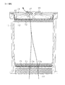
- the compressed air drying apparatus includes a support base 11, a cylindrical drying container 13 having a bottom, and a cylinder that covers the drying container 13 and is attached to the support base 11 and has an opening and a bottom. And a purge tank 14 having a shape.
- the purge tank 14 opens toward the support base 11.
- the drying container 13 is filled with a desiccant 12.
- the inlet 15 is provided on the front surface of the support base 11, and the outlet 20 is provided on the back surface of the support base 11.
- a cylindrical storage portion 21 that opens downward is formed inside the support base 11.
- a drain discharge device 25 is provided on the upper portion of the accommodating portion 21.
- a cylindrical exhaust pipe 17 is attached to the lower part of the drain discharge device 25 of the housing part 21.
- a drain outlet 19 as an outlet which is an outlet of the exhaust pipe 17 is open to the atmosphere.
- the drain discharge device 25 includes a drain valve 26 and a piston 27 for discharging a drain liquid containing oil and moisture.
- the drain valve 26 also serves as an open valve that discharges the drain liquid to the outside air during the unloading operation.
- the drain valve 26 is closed during a load operation in which moisture is removed from the compressed air.
- air is supplied from the governor 28 provided in the support base 11 to the control chamber 29 that is a space in the support base 11.
- the piston 27 is lowered and the drain valve 26 is opened.
- the drain valve 26 is opened, the drain liquid is vigorously discharged to the outside together with the compressed air.
- the exhaust pipe 17 is provided with a filter 31.
- the filter 31 is a metal material having fine ventilation holes inside, such as crushed aluminum, and functions as a silencer that reduces noise accompanying drain liquid discharge.
- the support base 11 is provided with a plurality of governor exhaust passages 37 through which the exhaust of the governor 28 passes through the governor exhaust passage 36.
- the governor exhaust passage 37 is a space formed by the inner wall of the accommodating portion 21 and the outer wall of the exhaust pipe 17.
- a governor exhaust port 38 that is an opening of the governor exhaust passage 37 is open to the atmosphere.
- the purge tank 14 covers the drying container 13 and is attached to the upper end of the support base 11 with bolts 24.
- a space formed by the inner wall of the purge tank 14 and the outer wall of the drying container 13 functions as a tank 16 for storing dehumidified compressed dry air.
- the desiccant 12 filled in the drying container 13 is sandwiched between the lower plate 45 and the upper plate 46 in the vertical direction.
- An oil separate filter 44 as a collision material is provided at the lower part of the drying container 13.
- the oil separate filter 44 is crushed aluminum.
- the oil separate filter 44 finely changes the flow of the compressed air inside thereof, so that the oil particles carried on the flow of the compressed air collide with the aluminum surface by the inertial force and are captured.
- a plurality of through holes are formed in the lower plate 45 and the upper plate 46.
- a first glass fiber filter 51 is provided on the upper surface of the lower plate 45.
- a second glass fiber filter 52 for holding the desiccant 12 is provided on the lower surface of the upper plate 46.
- These glass fiber filters 51 and 52 are formed by molding glass fibers into a substantially disk shape.
- the diameters of the glass fiber filters 51 and 52 are substantially the same as the inner diameter of the drying container 13.
- the glass fiber filters 51 and 52 have functions of holding the desiccant 12 and removing oil from the compressed air. In the present embodiment, these glass fiber filters 51 and 52 have the same thickness.
- the glass fiber filters 51 and 52 have a fiber diameter capable of capturing fine oil particles that perform Brownian motion in compressed air, a hole diameter, and a depth density.
- the collision with the oil separate filter 44 is most efficient for capturing oil particles having a relatively large particle diameter of, for example, 1 ⁇ m or more.
- the number of fine oil particles contained in the compressed air is larger than that of large diameter oil particles.
- Fine oil particles collide with gas molecules of compressed air, and thereby perform an irregular motion (Brownian motion) unrelated to the flow of compressed air.
- the particle size of the oil particles that move irregularly is, for example, 50 nm or less.
- Such fine oil particles are not easily captured by a method using inertial collision, and the capture by contact with the fibers of the glass fiber filters 51 and 52 is efficient.
- oil particles having an intermediate particle diameter such as more than 50 nm and less than 1 ⁇ m can be captured by the oil separate filter 44 and the glass fiber filters 51 and 52, although the efficiency is slightly reduced.
- a coil spring 42 is installed between the upper plate 46 and the lid member 41.
- the coil spring 42 presses the upper plate 46 downward by an urging force generated when the lid member 41 is fixed to the drying container 13.
- the glass fiber filters 51 and 52, the desiccant 12, and the oil separate filter 44 are urged by the coil spring 42.
- the lid member 41 has a first through hole 47 and a second through hole 48 formed therein.
- the first through hole 47 is provided with a check valve 39 that allows only air flow from the inside of the drying container 13 to the outside.
- the compressed air that has passed through the oil separation filter 44 passes through the hole 13 a formed in the bottom of the drying container 13 and the through hole of the lower plate 45, and passes through the first glass fiber filter 51. pass.
- the first glass fiber filter 51 By passing through the first glass fiber filter 51, most of the oil particles having a relatively small particle diameter are removed from the compressed air. In this way, when the compressed air having a reduced oil content passes through the desiccant 12, moisture is removed from the compressed air. At this time, since the oil is captured by the oil separate filter 44 and the glass fiber filter 51 before passing through the desiccant 12, clogging of the desiccant 12 is suppressed.
- the compressed air that has been dried by passing through the desiccant 12 passes through the second glass fiber filter 52, the through hole of the upper plate 46, and the first through hole 47 formed in the lid member 41, and passes through the purge tank 14. It is once stored in the tank 16 inside.
- the compressed dry air introduced into the tank 16 passes through the outlet 20 leaving a part and is stored in an external air tank.
- the compressed air in the air tank is used for the operation of each device of the air brake system, for example.
- the compressed air drying device shifts to an unload operation in which the desiccant is regenerated by the action of the governor 28 at the timing when the air pressure in the air tank reaches the upper limit.
- the governor 28 supplies the air to the control chamber 29 that drives the drain valve 26 and moves the piston 27 to open the drain valve 26.
- the drain valve 26 of the drain discharge device 25 is opened, the compressed dry air accumulated in the purge tank 14 flows from the upper side to the lower side of the drying container 13 and is compressed air from the drain outlet 19 of the drain discharge passage 18. At the same time, oil and water are discharged.
- the compressed dry air accumulated in the tank 16 flows into the drying container 13 through the second through hole 48 of the lid member 41, the through hole of the upper plate 46 and the second glass fiber filter 52. To do. At this time, at least a part of the oil trapped by the second glass fiber filter 52 is also removed from the compressed dry air.
- the compressed dry air regenerates the desiccant 12 by contacting the desiccant 12.
- the compressed air that has passed through the desiccant 12 and contained moisture or the like passes through the first glass fiber filter 51 and the through hole of the lower plate 45, and then passes through the oil separate filter 44. At this time, at least a part of the oil trapped by the first glass fiber filter 51 is also removed from the compressed air.
- the compressed air passes through the drain discharge device 25, passes through the filter 31 of the exhaust pipe 17, and is discharged together with the drain liquid.
- the following effects can be obtained. (1) Since the first glass fiber filter 51 and the second glass fiber filter 52 are provided upstream and downstream of the desiccant 12 in the air flow during the load operation, the glass fiber filters 51 and 52 Oil particles having a small particle diameter in the compressed air can be captured. For this reason, it is possible to improve the oil removal rate of the compressed air while removing moisture from the compressed air by the desiccant 12. Moreover, since the filter holding the desiccant 12 is formed from the glass fiber filters 51 and 52, it has oil trapping performance without newly securing a space for disposing the filter in the flow path of the compressed air. A filter can be provided.
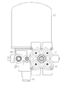
- the compressed air drying apparatus according to the second embodiment is different from the first embodiment in that it is a cartridge type in which the purge tank including the drying container can be replaced.
- the purge tank including the drying container can be replaced.
- the compressed air drying apparatus includes a cylindrical outer case 55 having a bottom portion and a support base 56 that supports the outer case 55.
- the outer case 55 is detachable from the support base 56.
- an inlet 57 into which compressed air supplied from a compressor (not shown) flows and an outlet 58 to which compressed dry air is supplied to an air tank (not shown) are the same on the side of the support base 56. It is provided in the direction.
- the outlet 58 is provided with a check valve (not shown). This check valve opens the outlet 58 during the load operation and closes the outlet 58 during the unload operation.
- a flange 58 a for attaching the protection valve 60 is provided at the outlet 58.
- the protection valve 60 is integrally provided with a plurality of pressure protection valves respectively corresponding to air tanks (brake circuits) (not shown). Therefore, the system including each air tank is independent. When the pressure of the compressed air in any one of the air tanks is reduced (defective), the protection valve 60 closes the pressure protection valve (not shown) corresponding to the air tank, so that other non-defective air tanks ( Functions to protect the brake circuit).
- the support base 56 is provided with a pressure governor 62.
- a drain discharge port 61 is provided as a discharge port for discharging drain liquid during unloading operation.
- a cylindrical inner cylindrical portion 65 is formed at the upper center of the support base 56.
- a male screw 65 a is formed on the upper outer periphery of the inner cylindrical portion 65.
- a cylindrical outer cylindrical portion 66 is formed on the upper outer edge portion of the support base 56.
- a space between the inner cylindrical portion 65 and the outer cylindrical portion 66 functions as a first tank 67 that stores the compressed air flowing in from the inlet 57.
- the drain discharge port 61 is provided with a drain valve device 80 that opens and closes the drain discharge port 61.
- An exhaust pipe 68 is exposed and attached to the drain outlet 61.
- a space 71 is formed in the center of the support base 56.
- the pressure governor 62 can supply compressed air to the space 71 via the communication path 69.
- the drain valve device 80 includes a valve body 81 for opening and closing the drain discharge port 61 and a piston 82 for moving the valve body 81.
- the valve body 81 is installed so as to move integrally with the piston 82 and to be seated on the valve seat 83 of the drain valve device 80.
- the piston 82 is installed in a state where the space 71 formed in the support base 56 is closed, and is biased upward by a biasing spring 84. When compressed air is supplied from the pressure governor 62 to the space 71, the piston 82 is pushed down. When the valve body 81 is pushed down together with the piston 82, the valve body 81 is separated from the valve seat 83, thereby opening the drain discharge port 61.
- the drain valve device 80 closes the drain outlet 61 during the load operation.
- compressed air is supplied from the pressure governor 62 to the space 71.
- the drain valve device 80 opens the drain outlet 61.
- the drain liquid containing the oil and moisture is vigorously discharged to the outside by the compressed air (purge air) flowing from the outside of the compressed air drying device through the open drain discharge port 61.
- the pressure in the outer case 55 decreases due to the discharge of the compressed air from the drain discharge port 61 and reaches the minimum predetermined value, the supply of the compressed air to the space 71 is stopped and the piston 82 is not pushed down. Therefore, the drain outlet 61 is closed by the biasing force of the biasing spring 84.
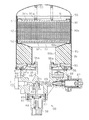
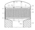
- the outer case 55 has a cylindrical outer case 85 having a bottom and an opening that opens toward the support base 56, and a mounting plate 86 that closes the opening of the outer case 85 and is attached to the support base 56. And a fixing member 87 for fixing the mounting plate 86 to the outer case 85.
- a cylindrical drying container 90 filled with the desiccant 12 is accommodated inside the outer case 85.
- the drying container 90 includes a large-diameter portion 90 a having an outer diameter substantially equal to the inner diameter of the outer case 85 and a small-diameter portion 90 b having an outer diameter that is approximately half the inner diameter of the outer case 85.
- the large diameter portion 90a and the small diameter portion 90b are connected by a connecting portion 90c.
- a female screw portion 86a is provided at the center of the mounting plate 86.
- the female screw portion 86 a is screwed into the male screw 65 a of the inner cylindrical portion 65 of the support base 56.
- the outer case 55 is attached to the support base 56 by screwing the female screw portion 86 a of the mounting plate 86 to the inner cylindrical portion 65.
- the mounting plate 86 has an outer edge portion of the fixing member 87 wound around the opening end of the outer case 85, and the hooking piece 87 a of the fixing member 87 is hooked in the hole 86 h of the mounting plate 86. It is fixed.
- a seal member 88 that is in close contact with the upper end portion of the support base 56 to form a sealed space is attached to the lower portion of the fixing member 87.
- the granular desiccant 12 filled in the drying container 90 is sandwiched between the upper plate 91 and the lower plate 92 in the vertical direction via the first glass fiber filter 51 and the second glass fiber filter 52. .
- a biasing spring 93 is installed inside the outer case 85.
- the urging spring 93 is installed in the spring receiving portion 91 a of the upper plate 91 and urges the upper plate 91 toward the lower plate 92.
- the upper plate 91 and the lower plate 92 have a plurality of through holes 91h and 92h.
- the upper plate 91 is formed with a groove extending radially from the spring receiving portion 91a.
- the glass fiber filters 51 and 52 have the same shape as the first embodiment.
- an oil adsorbent 95 is accommodated below the lower plate 92.
- the oil adsorbent 95 has a substantially annular shape, and is disposed in a space formed between the inner wall surface of the outer case 85 and the connecting portion 90c and the small diameter portion 90b of the drying container 90.
- the oil adsorbent 95 is made of a sponge having oil resistance, heat resistance, and moisture resistance. This oil adsorbent 95 captures oil particles having a relatively large diameter by electrostatic force.
- the oil adsorbent 95 is suitable for collecting oil particles having a particle size of 300 nm to 1 ⁇ m.
- the load operation starts when the pressure in the outer case 55 reaches the minimum predetermined value, and ends when the pressure in the air tank reaches the maximum predetermined value.
- the inlet 57 see FIG. 3
- the outlet 58 see FIG. 4
- the drain outlet 61 is closed.
- the unload operation starts when the pressure in the air tank reaches a maximum predetermined value, and ends when the pressure in the outer case 55 reaches a minimum predetermined value.
- the inlet 57 and the outlet 58 are closed, and the drain outlet 61 is opened.
- the compressed air flowing from the compressor (not shown) through the inlet 57 is introduced into the first tank 67.
- This compressed air flows into the oil adsorbing material 95 from the hole 86 h formed in the mounting plate 86.
- the relatively large diameter oil particles contained in the compressed air are captured by the oil adsorbent 95 by electrostatic force generated between the oil particles and the oil adsorbent 95.
- the glass fiber filter 51 captures minute oil particles that undergo Brownian motion.
- the compressed air from which many of the oil particles have been removed is sent to the desiccant 12.
- the compressed air from which moisture has been removed by contact with the desiccant 12 is sent to the small diameter portion 90 b of the drying container 90 and discharged from the outlet 58.
- the unload operation will be explained.
- the inlet 57 and the outlet 58 are closed and the drain outlet 61 is opened as in the first embodiment.
- the drain outlet 61 is opened, the drain liquid containing oil and water is vigorously discharged to the outside by the compressed dry air in the outer case 85.
- the compressed dry air accumulated in the outer case 85 passes through the second glass fiber filter 52 through the through hole 92 h of the lower plate 92 and is sent to the desiccant 12.
- the compressed dry air regenerates the desiccant 12 by contacting the desiccant 12.
- the compressed air that has passed through the desiccant 12 passes through the first glass fiber filter 51 and the through hole 91h of the upper plate 91, passes through a gap between the outer case 55 and the large diameter portion 90a, and then becomes an oil adsorbent. Pass through 95. At this time, not only the moisture of the desiccant 12 but also part of the oil trapped by the second glass fiber filter 52, the first glass fiber filter 51, and the oil adsorbent 95 is removed from the compressed air.
- the compressed air that has passed through the oil adsorbent 95 passes through the drain valve device 80 through the first tank 67, passes through the exhaust pipe 68, and is discharged together with the drain liquid.
- the discharge of the compressed air and the drain liquid stops.
- the pressure in the outer case 55 reaches the minimum predetermined pressure, the supply of compressed air from the pressure governor 62 is stopped, whereby air is discharged from the space 71, and the drain valve device 80 is attached to the biasing spring 84.
- the drain outlet 61 is closed by the force.
- the compressed air drying device shifts from the unload operation to the load operation.
- the effect (1) can be obtained, and the following effects can be further obtained.
- the glass fiber filters 51 and 52 are provided on the downstream side of the oil adsorbent 95 in the air flow during the load operation, the glass fiber filters 51 and 52 have a relatively large diameter due to the electrostatic force generated in the oil adsorbent 95.
- the oil particles can be captured in advance.
- the amount of oil captured by the glass fiber filters 51 and 52 reduces the filter capacity for a short time. None exceed.
- the first glass fiber filter 51 in the present embodiment is made of the same material as the second glass fiber filter 52, but is thinner than the second glass fiber filter 52.
- the first glass fiber filter 51 is composed of one filter
- the second glass fiber filter 52 is formed by stacking two or three same filters as the first glass fiber filter 51. It is configured. For this reason, even if the 1st glass fiber filter 51 absorbs a water
- the second glass fiber filter 52 is not exposed to moisture discharged from the desiccant 12.
- the first glass fiber filter 51 is exposed to the moisture discharged from the desiccant 12
- the first glass fiber filter 51 is thin and thus easily discharges moisture. For this reason, the oil removal performance is unlikely to deteriorate. Therefore, oil can be captured by the first glass fiber filter 51 even after restarting the load operation.
- the effects (1) and (2) are obtained, and the following effects are further obtained.
- (4) When the water discharged from the desiccant together with the compressed air during the unload operation passes through the upstream glass fiber filter during the load operation, that is, the first glass fiber filter 51, the glass fiber filter 51 To be absorbed.
- the thickness of the upstream glass fiber filter 51 during the load operation is smaller than the thickness of the downstream glass fiber filter, ie, the second glass fiber filter 52 during the load operation. Easy to be. For this reason, the fall of the oil capture
- each said embodiment can also be implemented with the following forms.
- the thickness of the first glass fiber filter 51 on the upstream side with respect to the desiccant 12 in the air flow during the load operation is set to be the same as that of the second glass fiber filter 52. Make it thinner than the thickness.
- the absorbed water can be easily discharged even if exposed to the water discharged from the desiccant 12 during the unloading operation. it can.
- the oil adsorbing material 95 in the second embodiment may be provided with a baffle plate 100 instead of the charging sponge.
- a baffle plate 100 By applying compressed air to the baffle plate 100, oil particles contained in the compressed air can collide with the baffle plate 100 and be captured.
- operation is replaced with a glass fiber filter.
- the filter 101 may be replaced with another filter 101 that has a higher moisture drainability.
- a filter having a lower moisture absorption rate than a glass fiber filter, such as a filter made of synthetic resin fibers, may be used.
- the first glass fiber filter 51 and the second glass fiber filter 52 are made of the same material, but the fiber diameter, hole diameter, and depth direction density of the first glass fiber filter 51 are set.
- the second glass fiber filter 52 may be different. For example, if the fiber diameter and the hole diameter are increased, the water discharge performance is enhanced.
- the first glass fiber filter is a single layer
- the second glass fiber filter 52 is a stack of two or three single-layer glass fiber filters.
- the number of laminated glass fiber filters 52 may be plural.
- the first glass fiber filter 51 may be a stack of a plurality of single-layer filters, and the number of laminated second glass fiber filters 52 may be larger than the number of laminated first glass fiber filters 51. Good.
- the filter provided on the side may have a laminated structure.
- the glass fiber filters 51 and 52 are formed in a disk shape, but other shapes may be used as long as the glass fiber filters 51 and 52 are provided in the middle of the flow path of the compressed air and can pass the compressed air. For example, it is good also as a shape which changed thickness in the center part and an outer edge part.
- Glass fiber filters 51 and 52 are formed by molding glass fibers. For example, glass fibers such as those in which glass fibers are supported on a base material, or glass fibers mixed with other materials, etc. And a filter made of other materials.
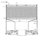
- a glass fiber filter 54 may be disposed between a pair of oil adsorbents 95a and 95b.
- the laminated structure which consists of the oil adsorbent 95 and the glass fiber filter 54 was made into 3 layers, it is good also as multiple layers of 3 layers or more.
- the glass fiber filter 51 on the upstream side with respect to the desiccant 12 is made of a nonwoven fabric or the like. Also good.
- the glass fiber filter 54 may be provided between the cover member 102 that supports the desiccant 12 and the desiccant 12.
- the cover member 102 has a cylindrical shape with one end closed, and a vent hole 102a is formed at least on the side wall on the glass fiber filter 54 side.
- the compressed dry air that has passed through the glass fiber filter 54 through the vent hole 102a passes to the support base 56 side.
- a glass fiber filter may be accommodated in the entire small diameter portion 90b of the drying container 90. This glass fiber filter has substantially the same diameter as the inner diameter of the small diameter portion 90b and is formed in an annular shape.
- the oil adsorbent 95 and the glass fiber filters 51 and 52 are provided as filters for capturing oil particles.
- the glass fiber filter is accommodated in the entire space in which the oil adsorbent 95 is provided. All the filters that capture oil particles may be glass fiber filters.
- the configuration of the compression drying apparatus may be a configuration other than the above embodiments as long as glass fiber filters can be mounted on the upstream side and the downstream side with respect to the desiccant in the flow path of the compressed air. Good.
Landscapes
- Chemical & Material Sciences (AREA)
- Engineering & Computer Science (AREA)
- Analytical Chemistry (AREA)
- General Chemical & Material Sciences (AREA)
- Oil, Petroleum & Natural Gas (AREA)
- Chemical Kinetics & Catalysis (AREA)
- Mechanical Engineering (AREA)
- General Engineering & Computer Science (AREA)
- Drying Of Gases (AREA)
- Filtering Of Dispersed Particles In Gases (AREA)
- Compressor (AREA)
- Filtering Materials (AREA)
- Separating Particles In Gases By Inertia (AREA)
- Electrostatic Separation (AREA)
Abstract
Priority Applications (4)
| Application Number | Priority Date | Filing Date | Title |
|---|---|---|---|
| CN201580003889.1A CN106029204B (zh) | 2014-01-10 | 2015-01-09 | 压缩空气干燥装置 |
| JP2015556848A JPWO2015105185A1 (ja) | 2014-01-10 | 2015-01-09 | 圧縮空気乾燥装置 |
| US15/110,294 US10130910B2 (en) | 2014-01-10 | 2015-01-09 | Compressed air drying device |
| DE112015000364.9T DE112015000364T5 (de) | 2014-01-10 | 2015-01-09 | Druckluft-Trocknungsvorrichtung |
Applications Claiming Priority (2)
| Application Number | Priority Date | Filing Date | Title |
|---|---|---|---|
| JP2014-003337 | 2014-01-10 | ||
| JP2014003337 | 2014-01-10 |
Publications (1)
| Publication Number | Publication Date |
|---|---|
| WO2015105185A1 true WO2015105185A1 (fr) | 2015-07-16 |
Family
ID=53524008
Family Applications (1)
| Application Number | Title | Priority Date | Filing Date |
|---|---|---|---|
| PCT/JP2015/050515 WO2015105185A1 (fr) | 2014-01-10 | 2015-01-09 | Dispositif d'assèchement d'air comprimé |
Country Status (5)
| Country | Link |
|---|---|
| US (1) | US10130910B2 (fr) |
| JP (2) | JPWO2015105185A1 (fr) |
| CN (1) | CN106029204B (fr) |
| DE (1) | DE112015000364T5 (fr) |
| WO (1) | WO2015105185A1 (fr) |
Cited By (1)
| Publication number | Priority date | Publication date | Assignee | Title |
|---|---|---|---|---|
| WO2016159109A1 (fr) * | 2015-03-31 | 2016-10-06 | ナブテスコオートモーティブ 株式会社 | Dispositif de séchage d'air comprimé |
Families Citing this family (4)
| Publication number | Priority date | Publication date | Assignee | Title |
|---|---|---|---|---|
| DE102018000981A1 (de) * | 2017-03-08 | 2018-09-13 | Mann+Hummel Gmbh | Strömungsoptimierte Trockenmittelkartusche |
| CN108854282A (zh) * | 2018-06-30 | 2018-11-23 | 中国船舶重工集团衡远科技有限公司 | 干燥微热气体过滤系统 |
| CN110478932B (zh) * | 2019-07-03 | 2021-06-22 | 杨春斌 | 一种工业用压缩空气净化设备 |
| CN113440986B (zh) * | 2021-07-06 | 2022-05-06 | 瑞立集团瑞安汽车零部件有限公司 | 组合式电控干燥器 |
Citations (13)
| Publication number | Priority date | Publication date | Assignee | Title |
|---|---|---|---|---|
| JPS50140965A (fr) * | 1974-02-13 | 1975-11-12 | ||
| JPS60115527U (ja) * | 1984-01-10 | 1985-08-05 | 株式会社ナブコ | 圧縮空気乾燥装置 |
| JPS6343628U (fr) * | 1986-09-09 | 1988-03-23 | ||
| JPS6377511A (ja) * | 1986-09-20 | 1988-04-07 | ドムニック ハンター リミテッド | フィルタ装置 |
| JPS6412624U (fr) * | 1987-07-10 | 1989-01-23 | ||
| JPH0266219U (fr) * | 1988-11-04 | 1990-05-18 | ||
| JPH08206437A (ja) * | 1995-01-31 | 1996-08-13 | Misuzu Mach Kk | 空気除湿装置 |
| JPH10296038A (ja) * | 1997-04-28 | 1998-11-10 | Nabco Ltd | 圧縮空気供給システムおよびエアドライヤ |
| JP2000325830A (ja) * | 1999-01-22 | 2000-11-28 | Sanyo Electric Co Ltd | 空気清浄機用放電電極 |
| JP2006320597A (ja) * | 2005-05-20 | 2006-11-30 | Fuso Sangyo Kk | ドリップバッグ |
| JP2008279370A (ja) * | 2007-05-10 | 2008-11-20 | Nabtesco Corp | エアドライヤおよび圧縮空気供給システム |
| JP2010188246A (ja) * | 2009-02-17 | 2010-09-02 | Aisin Seiki Co Ltd | 車両のエアサスペンション用ドライヤ |
| JP2011247590A (ja) * | 2010-05-21 | 2011-12-08 | Central Res Inst Of Electric Power Ind | 調理排気の測定方法 |
Family Cites Families (11)
| Publication number | Priority date | Publication date | Assignee | Title |
|---|---|---|---|---|
| US4029486A (en) * | 1976-02-25 | 1977-06-14 | Graham-White Sales Corporation | Pneumatic compactor for particulate desiccant |
| US4364756A (en) * | 1981-07-07 | 1982-12-21 | Virginia Chemicals Inc. | Refrigerant suction line filter/filter-drier and method for the construction thereof |
| US5364540A (en) * | 1993-02-11 | 1994-11-15 | Emerson Electric Co. | Filter drier and method of filtering a fluid stream |
| US5427609A (en) * | 1993-09-14 | 1995-06-27 | Horton Industries, Inc. | Device for cleaning and drying compressed gas |
| CN2536811Y (zh) | 2002-03-20 | 2003-02-19 | 陈勇 | 高效多功能压缩空气干燥除油过滤器 |
| DE102006037307A1 (de) * | 2006-08-08 | 2008-02-14 | Knorr-Bremse Systeme für Nutzfahrzeuge GmbH | Druckluftversorgungseinrichtung für ein Nutzfahrzeug und Lufttrocknerpatrone |
| JP2011247690A (ja) | 2010-05-25 | 2011-12-08 | Fujitsu Ltd | コネクターピン検査装置およびその検査方法 |
| JP5666256B2 (ja) * | 2010-11-15 | 2015-02-12 | ナブテスコオートモーティブ株式会社 | エアドライヤ |
| WO2013129495A1 (fr) * | 2012-02-27 | 2013-09-06 | ナブテスコオートモーティブ 株式会社 | Séparateur d'huile |
| CN104302878B (zh) * | 2012-02-27 | 2020-03-13 | 纳博特斯克汽车零部件有限公司 | 具备压缩机、空气干燥器以及油分离器的系统 |
| CN203002112U (zh) * | 2012-11-17 | 2013-06-19 | 好利旺机械(上海)有限公司 | 空气过滤器 |
-
2015
- 2015-01-09 US US15/110,294 patent/US10130910B2/en active Active
- 2015-01-09 CN CN201580003889.1A patent/CN106029204B/zh active Active
- 2015-01-09 JP JP2015556848A patent/JPWO2015105185A1/ja active Pending
- 2015-01-09 DE DE112015000364.9T patent/DE112015000364T5/de active Pending
- 2015-01-09 WO PCT/JP2015/050515 patent/WO2015105185A1/fr active Application Filing
-
2019
- 2019-05-30 JP JP2019101135A patent/JP6780059B2/ja active Active
Patent Citations (13)
| Publication number | Priority date | Publication date | Assignee | Title |
|---|---|---|---|---|
| JPS50140965A (fr) * | 1974-02-13 | 1975-11-12 | ||
| JPS60115527U (ja) * | 1984-01-10 | 1985-08-05 | 株式会社ナブコ | 圧縮空気乾燥装置 |
| JPS6343628U (fr) * | 1986-09-09 | 1988-03-23 | ||
| JPS6377511A (ja) * | 1986-09-20 | 1988-04-07 | ドムニック ハンター リミテッド | フィルタ装置 |
| JPS6412624U (fr) * | 1987-07-10 | 1989-01-23 | ||
| JPH0266219U (fr) * | 1988-11-04 | 1990-05-18 | ||
| JPH08206437A (ja) * | 1995-01-31 | 1996-08-13 | Misuzu Mach Kk | 空気除湿装置 |
| JPH10296038A (ja) * | 1997-04-28 | 1998-11-10 | Nabco Ltd | 圧縮空気供給システムおよびエアドライヤ |
| JP2000325830A (ja) * | 1999-01-22 | 2000-11-28 | Sanyo Electric Co Ltd | 空気清浄機用放電電極 |
| JP2006320597A (ja) * | 2005-05-20 | 2006-11-30 | Fuso Sangyo Kk | ドリップバッグ |
| JP2008279370A (ja) * | 2007-05-10 | 2008-11-20 | Nabtesco Corp | エアドライヤおよび圧縮空気供給システム |
| JP2010188246A (ja) * | 2009-02-17 | 2010-09-02 | Aisin Seiki Co Ltd | 車両のエアサスペンション用ドライヤ |
| JP2011247590A (ja) * | 2010-05-21 | 2011-12-08 | Central Res Inst Of Electric Power Ind | 調理排気の測定方法 |
Cited By (1)
| Publication number | Priority date | Publication date | Assignee | Title |
|---|---|---|---|---|
| WO2016159109A1 (fr) * | 2015-03-31 | 2016-10-06 | ナブテスコオートモーティブ 株式会社 | Dispositif de séchage d'air comprimé |
Also Published As
| Publication number | Publication date |
|---|---|
| CN106029204A (zh) | 2016-10-12 |
| US10130910B2 (en) | 2018-11-20 |
| US20160325224A1 (en) | 2016-11-10 |
| JP6780059B2 (ja) | 2020-11-04 |
| CN106029204B (zh) | 2018-07-03 |
| JP2019147152A (ja) | 2019-09-05 |
| JPWO2015105185A1 (ja) | 2017-03-23 |
| DE112015000364T5 (de) | 2016-10-06 |
Similar Documents
| Publication | Publication Date | Title |
|---|---|---|
| JP6780059B2 (ja) | 圧縮空気乾燥装置 | |
| JP6373757B2 (ja) | 圧縮空気乾燥装置 | |
| JP6609545B2 (ja) | オイルセパレータ | |
| US7691163B2 (en) | Vehicle air dryer | |
| US8852327B1 (en) | Air dryer cartridge with integrated check valve | |
| KR20140092349A (ko) | 압축 공기 처리 설비의 압축 공기 처리를 위한 공기 필터 카트리지 | |
| RU2492915C2 (ru) | Патрон для осушителя воздуха (варианты) | |
| WO2015163451A1 (fr) | Système de séchage à l'air comprimé et procédé de régénération pour système de séchage à l'air comprimé | |
| KR102248425B1 (ko) | 공기 건조기 카트리지 | |
| WO2017094758A1 (fr) | Dispositif de séparation gaz-liquide | |
| JP6779962B2 (ja) | 圧縮空気乾燥装置 | |
| WO2015088027A1 (fr) | Dispositif de séchage d'air comprimé | |
| JP6144154B2 (ja) | 圧縮空気乾燥装置 | |
| CN107708841B (zh) | 压缩空气干燥装置 | |
| JP2016190207A (ja) | 圧縮空気乾燥装置 | |
| JPWO2015182583A1 (ja) | エアドライヤ | |
| JP6126393B2 (ja) | エアドライヤ装置用排出ミスト捕捉装置 | |
| KR102490306B1 (ko) | 상용차용 공기 건조기 카트리지 | |
| JPH0664713U (ja) | 除湿器 | |
| JP2014024030A (ja) | 圧縮空気乾燥装置 | |
| JPS6078617A (ja) | 圧縮空気乾燥装置における再生用圧縮空気の確保方法 |
Legal Events
| Date | Code | Title | Description |
|---|---|---|---|
| 121 | Ep: the epo has been informed by wipo that ep was designated in this application |
Ref document number: 15734883 Country of ref document: EP Kind code of ref document: A1 |
|
| ENP | Entry into the national phase |
Ref document number: 2015556848 Country of ref document: JP Kind code of ref document: A |
|
| WWE | Wipo information: entry into national phase |
Ref document number: 15110294 Country of ref document: US |
|
| WWE | Wipo information: entry into national phase |
Ref document number: 112015000364 Country of ref document: DE |
|
| 122 | Ep: pct application non-entry in european phase |
Ref document number: 15734883 Country of ref document: EP Kind code of ref document: A1 |