WO2015105168A1 - 化粧シート及び化粧板、並びに、それらの製造方法 - Google Patents
化粧シート及び化粧板、並びに、それらの製造方法 Download PDFInfo
- Publication number
- WO2015105168A1 WO2015105168A1 PCT/JP2015/050447 JP2015050447W WO2015105168A1 WO 2015105168 A1 WO2015105168 A1 WO 2015105168A1 JP 2015050447 W JP2015050447 W JP 2015050447W WO 2015105168 A1 WO2015105168 A1 WO 2015105168A1
- Authority
- WO
- WIPO (PCT)
- Prior art keywords
- layer
- sheet
- decorative sheet
- surface protective
- protective layer
- Prior art date
Links
- 238000000034 method Methods 0.000 title description 94
- 229920005989 resin Polymers 0.000 claims abstract description 246
- 239000011347 resin Substances 0.000 claims abstract description 246
- 229920005992 thermoplastic resin Polymers 0.000 claims abstract description 49
- 229910052736 halogen Inorganic materials 0.000 claims abstract description 37
- 150000002367 halogens Chemical class 0.000 claims abstract description 35
- 239000011093 chipboard Substances 0.000 claims abstract description 30
- 238000010030 laminating Methods 0.000 claims abstract description 25
- 239000000758 substrate Substances 0.000 claims abstract description 21
- 239000010410 layer Substances 0.000 claims description 570
- 239000011241 protective layer Substances 0.000 claims description 265
- 239000010419 fine particle Substances 0.000 claims description 95
- 239000000463 material Substances 0.000 claims description 92
- 241000428199 Mustelinae Species 0.000 claims description 45
- 239000002245 particle Substances 0.000 claims description 45
- 238000004049 embossing Methods 0.000 claims description 42
- 239000011342 resin composition Substances 0.000 claims description 36
- 238000004519 manufacturing process Methods 0.000 claims description 28
- VYPSYNLAJGMNEJ-UHFFFAOYSA-N Silicium dioxide Chemical compound O=[Si]=O VYPSYNLAJGMNEJ-UHFFFAOYSA-N 0.000 claims description 25
- 230000005865 ionizing radiation Effects 0.000 claims description 23
- 238000000576 coating method Methods 0.000 claims description 21
- 238000004804 winding Methods 0.000 claims description 14
- 239000000377 silicon dioxide Substances 0.000 claims description 10
- 239000011248 coating agent Substances 0.000 claims description 9
- 150000001336 alkenes Chemical class 0.000 claims description 8
- JRZJOMJEPLMPRA-UHFFFAOYSA-N olefin Natural products CCCCCCCC=C JRZJOMJEPLMPRA-UHFFFAOYSA-N 0.000 claims description 8
- 239000002131 composite material Substances 0.000 claims description 6
- 239000002344 surface layer Substances 0.000 claims description 5
- BZHJMEDXRYGGRV-UHFFFAOYSA-N Vinyl chloride Chemical compound ClC=C BZHJMEDXRYGGRV-UHFFFAOYSA-N 0.000 abstract description 19
- 230000033228 biological regulation Effects 0.000 abstract description 10
- 238000011156 evaluation Methods 0.000 description 87
- 238000012360 testing method Methods 0.000 description 40
- -1 polyethylene terephthalate Polymers 0.000 description 36
- 239000002023 wood Substances 0.000 description 36
- 239000003795 chemical substances by application Substances 0.000 description 35
- 239000012790 adhesive layer Substances 0.000 description 25
- 238000013461 design Methods 0.000 description 22
- 229920002803 thermoplastic polyurethane Polymers 0.000 description 22
- 239000000203 mixture Substances 0.000 description 21
- 239000000853 adhesive Substances 0.000 description 20
- 230000000052 comparative effect Effects 0.000 description 20
- 239000000049 pigment Substances 0.000 description 20
- 238000010894 electron beam technology Methods 0.000 description 18
- 239000002932 luster Substances 0.000 description 17
- NIXOWILDQLNWCW-UHFFFAOYSA-M Acrylate Chemical compound [O-]C(=O)C=C NIXOWILDQLNWCW-UHFFFAOYSA-M 0.000 description 16
- 239000000654 additive Substances 0.000 description 16
- 230000001070 adhesive effect Effects 0.000 description 16
- 239000003086 colorant Substances 0.000 description 15
- 229920001155 polypropylene Polymers 0.000 description 15
- 238000007639 printing Methods 0.000 description 15
- 239000000047 product Substances 0.000 description 15
- 238000001125 extrusion Methods 0.000 description 14
- 239000004743 Polypropylene Substances 0.000 description 13
- 238000003475 lamination Methods 0.000 description 13
- 230000003068 static effect Effects 0.000 description 13
- 230000003746 surface roughness Effects 0.000 description 13
- 230000000996 additive effect Effects 0.000 description 11
- JOYRKODLDBILNP-UHFFFAOYSA-N Ethyl urethane Chemical compound CCOC(N)=O JOYRKODLDBILNP-UHFFFAOYSA-N 0.000 description 9
- 239000003242 anti bacterial agent Substances 0.000 description 9
- 230000000694 effects Effects 0.000 description 9
- 239000002904 solvent Substances 0.000 description 9
- VTYYLEPIZMXCLO-UHFFFAOYSA-L Calcium carbonate Chemical compound [Ca+2].[O-]C([O-])=O VTYYLEPIZMXCLO-UHFFFAOYSA-L 0.000 description 8
- 239000004606 Fillers/Extenders Substances 0.000 description 8
- 238000005259 measurement Methods 0.000 description 8
- 230000001681 protective effect Effects 0.000 description 8
- 239000004925 Acrylic resin Substances 0.000 description 7
- 239000011162 core material Substances 0.000 description 7
- 238000003851 corona treatment Methods 0.000 description 7
- 238000001035 drying Methods 0.000 description 7
- 239000000839 emulsion Substances 0.000 description 7
- 239000000945 filler Substances 0.000 description 7
- 229920005862 polyol Polymers 0.000 description 7
- 229920002554 vinyl polymer Polymers 0.000 description 7
- 229920000178 Acrylic resin Polymers 0.000 description 6
- 239000004698 Polyethylene Substances 0.000 description 6
- DNIAPMSPPWPWGF-UHFFFAOYSA-N Propylene glycol Chemical compound CC(O)CO DNIAPMSPPWPWGF-UHFFFAOYSA-N 0.000 description 6
- 239000006096 absorbing agent Substances 0.000 description 6
- NIXOWILDQLNWCW-UHFFFAOYSA-N acrylic acid group Chemical group C(C=C)(=O)O NIXOWILDQLNWCW-UHFFFAOYSA-N 0.000 description 6
- 229920001577 copolymer Polymers 0.000 description 6
- UHESRSKEBRADOO-UHFFFAOYSA-N ethyl carbamate;prop-2-enoic acid Chemical compound OC(=O)C=C.CCOC(N)=O UHESRSKEBRADOO-UHFFFAOYSA-N 0.000 description 6
- 229910052751 metal Inorganic materials 0.000 description 6
- 239000002184 metal Substances 0.000 description 6
- 238000002156 mixing Methods 0.000 description 6
- 239000000178 monomer Substances 0.000 description 6
- 239000003960 organic solvent Substances 0.000 description 6
- 229920000573 polyethylene Polymers 0.000 description 6
- 229920001169 thermoplastic Polymers 0.000 description 6
- 239000004416 thermosoftening plastic Substances 0.000 description 6
- XLYOFNOQVPJJNP-UHFFFAOYSA-N water Substances O XLYOFNOQVPJJNP-UHFFFAOYSA-N 0.000 description 6
- RTZKZFJDLAIYFH-UHFFFAOYSA-N Diethyl ether Chemical compound CCOCC RTZKZFJDLAIYFH-UHFFFAOYSA-N 0.000 description 5
- 239000005057 Hexamethylene diisocyanate Substances 0.000 description 5
- 239000003963 antioxidant agent Substances 0.000 description 5
- 238000004040 coloring Methods 0.000 description 5
- 239000007799 cork Substances 0.000 description 5
- 239000000975 dye Substances 0.000 description 5
- 239000003063 flame retardant Substances 0.000 description 5
- 239000004088 foaming agent Substances 0.000 description 5
- 238000007646 gravure printing Methods 0.000 description 5
- RRAMGCGOFNQTLD-UHFFFAOYSA-N hexamethylene diisocyanate Chemical compound O=C=NCCCCCCN=C=O RRAMGCGOFNQTLD-UHFFFAOYSA-N 0.000 description 5
- 239000012948 isocyanate Substances 0.000 description 5
- 150000002513 isocyanates Chemical class 0.000 description 5
- 239000004611 light stabiliser Substances 0.000 description 5
- 239000000314 lubricant Substances 0.000 description 5
- 229920000728 polyester Polymers 0.000 description 5
- 150000003077 polyols Chemical class 0.000 description 5
- 241000272525 Anas platyrhynchos Species 0.000 description 4
- KAKZBPTYRLMSJV-UHFFFAOYSA-N Butadiene Chemical compound C=CC=C KAKZBPTYRLMSJV-UHFFFAOYSA-N 0.000 description 4
- 239000004593 Epoxy Substances 0.000 description 4
- LFQSCWFLJHTTHZ-UHFFFAOYSA-N Ethanol Chemical compound CCO LFQSCWFLJHTTHZ-UHFFFAOYSA-N 0.000 description 4
- 244000043261 Hevea brasiliensis Species 0.000 description 4
- 229920000877 Melamine resin Polymers 0.000 description 4
- GWEVSGVZZGPLCZ-UHFFFAOYSA-N Titan oxide Chemical compound O=[Ti]=O GWEVSGVZZGPLCZ-UHFFFAOYSA-N 0.000 description 4
- 229910000019 calcium carbonate Inorganic materials 0.000 description 4
- 239000012461 cellulose resin Substances 0.000 description 4
- 238000006243 chemical reaction Methods 0.000 description 4
- 239000004927 clay Substances 0.000 description 4
- 229910003460 diamond Inorganic materials 0.000 description 4
- 239000010432 diamond Substances 0.000 description 4
- 239000002612 dispersion medium Substances 0.000 description 4
- 229920001971 elastomer Polymers 0.000 description 4
- 239000012467 final product Substances 0.000 description 4
- 238000009408 flooring Methods 0.000 description 4
- 238000007373 indentation Methods 0.000 description 4
- JDSHMPZPIAZGSV-UHFFFAOYSA-N melamine Chemical compound NC1=NC(N)=NC(N)=N1 JDSHMPZPIAZGSV-UHFFFAOYSA-N 0.000 description 4
- 229920003052 natural elastomer Polymers 0.000 description 4
- 229920001194 natural rubber Polymers 0.000 description 4
- 239000000123 paper Substances 0.000 description 4
- 229920003023 plastic Polymers 0.000 description 4
- 229920001200 poly(ethylene-vinyl acetate) Polymers 0.000 description 4
- 229920000139 polyethylene terephthalate Polymers 0.000 description 4
- 239000005020 polyethylene terephthalate Substances 0.000 description 4
- 229920005629 polypropylene homopolymer Polymers 0.000 description 4
- 229920002689 polyvinyl acetate Polymers 0.000 description 4
- 239000011118 polyvinyl acetate Substances 0.000 description 4
- 229920000915 polyvinyl chloride Polymers 0.000 description 4
- 239000004800 polyvinyl chloride Substances 0.000 description 4
- 230000001629 suppression Effects 0.000 description 4
- 229920003002 synthetic resin Polymers 0.000 description 4
- 239000000057 synthetic resin Substances 0.000 description 4
- DHKHKXVYLBGOIT-UHFFFAOYSA-N 1,1-Diethoxyethane Chemical compound CCOC(C)OCC DHKHKXVYLBGOIT-UHFFFAOYSA-N 0.000 description 3
- ZWEHNKRNPOVVGH-UHFFFAOYSA-N 2-Butanone Chemical compound CCC(C)=O ZWEHNKRNPOVVGH-UHFFFAOYSA-N 0.000 description 3
- TXBCBTDQIULDIA-UHFFFAOYSA-N 2-[[3-hydroxy-2,2-bis(hydroxymethyl)propoxy]methyl]-2-(hydroxymethyl)propane-1,3-diol Chemical compound OCC(CO)(CO)COCC(CO)(CO)CO TXBCBTDQIULDIA-UHFFFAOYSA-N 0.000 description 3
- CSCPPACGZOOCGX-UHFFFAOYSA-N Acetone Chemical compound CC(C)=O CSCPPACGZOOCGX-UHFFFAOYSA-N 0.000 description 3
- 229920000742 Cotton Polymers 0.000 description 3
- YMWUJEATGCHHMB-UHFFFAOYSA-N Dichloromethane Chemical compound ClCCl YMWUJEATGCHHMB-UHFFFAOYSA-N 0.000 description 3
- XEKOWRVHYACXOJ-UHFFFAOYSA-N Ethyl acetate Chemical compound CCOC(C)=O XEKOWRVHYACXOJ-UHFFFAOYSA-N 0.000 description 3
- LYCAIKOWRPUZTN-UHFFFAOYSA-N Ethylene glycol Chemical compound OCCO LYCAIKOWRPUZTN-UHFFFAOYSA-N 0.000 description 3
- KFZMGEQAYNKOFK-UHFFFAOYSA-N Isopropanol Chemical compound CC(C)O KFZMGEQAYNKOFK-UHFFFAOYSA-N 0.000 description 3
- OKKJLVBELUTLKV-UHFFFAOYSA-N Methanol Chemical compound OC OKKJLVBELUTLKV-UHFFFAOYSA-N 0.000 description 3
- 239000004793 Polystyrene Substances 0.000 description 3
- YXFVVABEGXRONW-UHFFFAOYSA-N Toluene Chemical compound CC1=CC=CC=C1 YXFVVABEGXRONW-UHFFFAOYSA-N 0.000 description 3
- ZMANZCXQSJIPKH-UHFFFAOYSA-N Triethylamine Chemical compound CCN(CC)CC ZMANZCXQSJIPKH-UHFFFAOYSA-N 0.000 description 3
- 239000004676 acrylonitrile butadiene styrene Substances 0.000 description 3
- 125000003647 acryloyl group Chemical group O=C([*])C([H])=C([H])[H] 0.000 description 3
- 239000011230 binding agent Substances 0.000 description 3
- 229920001400 block copolymer Polymers 0.000 description 3
- 238000010276 construction Methods 0.000 description 3
- 239000002537 cosmetic Substances 0.000 description 3
- MTHSVFCYNBDYFN-UHFFFAOYSA-N diethylene glycol Chemical compound OCCOCCO MTHSVFCYNBDYFN-UHFFFAOYSA-N 0.000 description 3
- 150000002148 esters Chemical class 0.000 description 3
- 235000019441 ethanol Nutrition 0.000 description 3
- 239000004744 fabric Substances 0.000 description 3
- 238000007756 gravure coating Methods 0.000 description 3
- 238000010438 heat treatment Methods 0.000 description 3
- VTHJTEIRLNZDEV-UHFFFAOYSA-L magnesium dihydroxide Chemical compound [OH-].[OH-].[Mg+2] VTHJTEIRLNZDEV-UHFFFAOYSA-L 0.000 description 3
- 239000000347 magnesium hydroxide Substances 0.000 description 3
- 229910001862 magnesium hydroxide Inorganic materials 0.000 description 3
- 150000002739 metals Chemical class 0.000 description 3
- VLKZOEOYAKHREP-UHFFFAOYSA-N n-Hexane Chemical compound CCCCCC VLKZOEOYAKHREP-UHFFFAOYSA-N 0.000 description 3
- 238000005498 polishing Methods 0.000 description 3
- 229920002037 poly(vinyl butyral) polymer Polymers 0.000 description 3
- 229920000058 polyacrylate Polymers 0.000 description 3
- 150000004291 polyenes Chemical class 0.000 description 3
- 229920002223 polystyrene Polymers 0.000 description 3
- 229920002635 polyurethane Polymers 0.000 description 3
- 239000004814 polyurethane Substances 0.000 description 3
- 239000004576 sand Substances 0.000 description 3
- 239000002356 single layer Substances 0.000 description 3
- 239000004575 stone Substances 0.000 description 3
- 150000003673 urethanes Chemical class 0.000 description 3
- JYEUMXHLPRZUAT-UHFFFAOYSA-N 1,2,3-triazine Chemical compound C1=CN=NN=C1 JYEUMXHLPRZUAT-UHFFFAOYSA-N 0.000 description 2
- NLHHRLWOUZZQLW-UHFFFAOYSA-N Acrylonitrile Chemical compound C=CC#N NLHHRLWOUZZQLW-UHFFFAOYSA-N 0.000 description 2
- 241000218645 Cedrus Species 0.000 description 2
- RYGMFSIKBFXOCR-UHFFFAOYSA-N Copper Chemical compound [Cu] RYGMFSIKBFXOCR-UHFFFAOYSA-N 0.000 description 2
- 229920000089 Cyclic olefin copolymer Polymers 0.000 description 2
- YNQLUTRBYVCPMQ-UHFFFAOYSA-N Ethylbenzene Chemical compound CCC1=CC=CC=C1 YNQLUTRBYVCPMQ-UHFFFAOYSA-N 0.000 description 2
- 239000005977 Ethylene Substances 0.000 description 2
- 239000004716 Ethylene/acrylic acid copolymer Substances 0.000 description 2
- 229920002430 Fibre-reinforced plastic Polymers 0.000 description 2
- UQSXHKLRYXJYBZ-UHFFFAOYSA-N Iron oxide Chemical compound [Fe]=O UQSXHKLRYXJYBZ-UHFFFAOYSA-N 0.000 description 2
- IMNFDUFMRHMDMM-UHFFFAOYSA-N N-Heptane Chemical compound CCCCCCC IMNFDUFMRHMDMM-UHFFFAOYSA-N 0.000 description 2
- 229920002292 Nylon 6 Polymers 0.000 description 2
- 229920002302 Nylon 6,6 Polymers 0.000 description 2
- 235000008331 Pinus X rigitaeda Nutrition 0.000 description 2
- 235000011613 Pinus brutia Nutrition 0.000 description 2
- 241000018646 Pinus brutia Species 0.000 description 2
- 239000004642 Polyimide Substances 0.000 description 2
- 239000004721 Polyphenylene oxide Substances 0.000 description 2
- PPBRXRYQALVLMV-UHFFFAOYSA-N Styrene Chemical compound C=CC1=CC=CC=C1 PPBRXRYQALVLMV-UHFFFAOYSA-N 0.000 description 2
- 240000002871 Tectona grandis Species 0.000 description 2
- WYURNTSHIVDZCO-UHFFFAOYSA-N Tetrahydrofuran Chemical compound C1CCOC1 WYURNTSHIVDZCO-UHFFFAOYSA-N 0.000 description 2
- QYKIQEUNHZKYBP-UHFFFAOYSA-N Vinyl ether Chemical compound C=COC=C QYKIQEUNHZKYBP-UHFFFAOYSA-N 0.000 description 2
- 238000010521 absorption reaction Methods 0.000 description 2
- 230000001133 acceleration Effects 0.000 description 2
- 239000011354 acetal resin Substances 0.000 description 2
- XECAHXYUAAWDEL-UHFFFAOYSA-N acrylonitrile butadiene styrene Chemical compound C=CC=C.C=CC#N.C=CC1=CC=CC=C1 XECAHXYUAAWDEL-UHFFFAOYSA-N 0.000 description 2
- 229920000122 acrylonitrile butadiene styrene Polymers 0.000 description 2
- 238000007754 air knife coating Methods 0.000 description 2
- XXROGKLTLUQVRX-UHFFFAOYSA-N allyl alcohol Chemical compound OCC=C XXROGKLTLUQVRX-UHFFFAOYSA-N 0.000 description 2
- 230000000844 anti-bacterial effect Effects 0.000 description 2
- 239000002216 antistatic agent Substances 0.000 description 2
- QVGXLLKOCUKJST-UHFFFAOYSA-N atomic oxygen Chemical compound [O] QVGXLLKOCUKJST-UHFFFAOYSA-N 0.000 description 2
- TZCXTZWJZNENPQ-UHFFFAOYSA-L barium sulfate Chemical compound [Ba+2].[O-]S([O-])(=O)=O TZCXTZWJZNENPQ-UHFFFAOYSA-L 0.000 description 2
- 239000012965 benzophenone Substances 0.000 description 2
- 230000015572 biosynthetic process Effects 0.000 description 2
- 125000000484 butyl group Chemical group [H]C([*])([H])C([H])([H])C([H])([H])C([H])([H])[H] 0.000 description 2
- QHIWVLPBUQWDMQ-UHFFFAOYSA-N butyl prop-2-enoate;methyl 2-methylprop-2-enoate;prop-2-enoic acid Chemical compound OC(=O)C=C.COC(=O)C(C)=C.CCCCOC(=O)C=C QHIWVLPBUQWDMQ-UHFFFAOYSA-N 0.000 description 2
- 239000001639 calcium acetate Substances 0.000 description 2
- OSGAYBCDTDRGGQ-UHFFFAOYSA-L calcium sulfate Chemical compound [Ca+2].[O-]S([O-])(=O)=O OSGAYBCDTDRGGQ-UHFFFAOYSA-L 0.000 description 2
- 239000006229 carbon black Substances 0.000 description 2
- 239000000919 ceramic Substances 0.000 description 2
- 150000001875 compounds Chemical class 0.000 description 2
- 238000004132 cross linking Methods 0.000 description 2
- JHIVVAPYMSGYDF-UHFFFAOYSA-N cyclohexanone Chemical compound O=C1CCCCC1 JHIVVAPYMSGYDF-UHFFFAOYSA-N 0.000 description 2
- 238000010586 diagram Methods 0.000 description 2
- 238000007607 die coating method Methods 0.000 description 2
- 238000003618 dip coating Methods 0.000 description 2
- 208000028659 discharge Diseases 0.000 description 2
- 239000000806 elastomer Substances 0.000 description 2
- 230000007613 environmental effect Effects 0.000 description 2
- 239000003822 epoxy resin Substances 0.000 description 2
- HQQADJVZYDDRJT-UHFFFAOYSA-N ethene;prop-1-ene Chemical group C=C.CC=C HQQADJVZYDDRJT-UHFFFAOYSA-N 0.000 description 2
- 239000011094 fiberboard Substances 0.000 description 2
- 239000011151 fibre-reinforced plastic Substances 0.000 description 2
- 125000000524 functional group Chemical group 0.000 description 2
- 239000011521 glass Substances 0.000 description 2
- 230000009477 glass transition Effects 0.000 description 2
- 239000010438 granite Substances 0.000 description 2
- LNEPOXFFQSENCJ-UHFFFAOYSA-N haloperidol Chemical compound C1CC(O)(C=2C=CC(Cl)=CC=2)CCN1CCCC(=O)C1=CC=C(F)C=C1 LNEPOXFFQSENCJ-UHFFFAOYSA-N 0.000 description 2
- 229920001903 high density polyethylene Polymers 0.000 description 2
- 239000004700 high-density polyethylene Substances 0.000 description 2
- 230000002706 hydrostatic effect Effects 0.000 description 2
- 239000003999 initiator Substances 0.000 description 2
- 239000001023 inorganic pigment Substances 0.000 description 2
- 238000009413 insulation Methods 0.000 description 2
- 229920000554 ionomer Polymers 0.000 description 2
- 230000001678 irradiating effect Effects 0.000 description 2
- ZXEKIIBDNHEJCQ-UHFFFAOYSA-N isobutanol Chemical compound CC(C)CO ZXEKIIBDNHEJCQ-UHFFFAOYSA-N 0.000 description 2
- 238000007759 kiss coating Methods 0.000 description 2
- 229920000092 linear low density polyethylene Polymers 0.000 description 2
- 239000004707 linear low-density polyethylene Substances 0.000 description 2
- 229920001684 low density polyethylene Polymers 0.000 description 2
- 239000004702 low-density polyethylene Substances 0.000 description 2
- 230000000873 masking effect Effects 0.000 description 2
- 239000006224 matting agent Substances 0.000 description 2
- 239000002609 medium Substances 0.000 description 2
- 229920001179 medium density polyethylene Polymers 0.000 description 2
- 239000004701 medium-density polyethylene Substances 0.000 description 2
- UAEPNZWRGJTJPN-UHFFFAOYSA-N methylcyclohexane Chemical compound CC1CCCCC1 UAEPNZWRGJTJPN-UHFFFAOYSA-N 0.000 description 2
- 125000005487 naphthalate group Chemical group 0.000 description 2
- 238000007645 offset printing Methods 0.000 description 2
- 239000012860 organic pigment Substances 0.000 description 2
- 229910052760 oxygen Inorganic materials 0.000 description 2
- 239000001301 oxygen Substances 0.000 description 2
- 239000005011 phenolic resin Substances 0.000 description 2
- 239000004033 plastic Substances 0.000 description 2
- 239000011120 plywood Substances 0.000 description 2
- 229920001084 poly(chloroprene) Polymers 0.000 description 2
- 229920001483 poly(ethyl methacrylate) polymer Polymers 0.000 description 2
- 229920003229 poly(methyl methacrylate) Polymers 0.000 description 2
- 229920002647 polyamide Polymers 0.000 description 2
- 229920006122 polyamide resin Polymers 0.000 description 2
- 229920001230 polyarylate Polymers 0.000 description 2
- 229920001083 polybutene Polymers 0.000 description 2
- 229920001707 polybutylene terephthalate Polymers 0.000 description 2
- 239000004417 polycarbonate Substances 0.000 description 2
- 229920000515 polycarbonate Polymers 0.000 description 2
- 229920000647 polyepoxide Polymers 0.000 description 2
- 229920005906 polyester polyol Polymers 0.000 description 2
- 229920001225 polyester resin Polymers 0.000 description 2
- 239000004645 polyester resin Substances 0.000 description 2
- 229920000570 polyether Polymers 0.000 description 2
- 229920000120 polyethyl acrylate Polymers 0.000 description 2
- 229920001721 polyimide Polymers 0.000 description 2
- 239000004926 polymethyl methacrylate Substances 0.000 description 2
- 229920000306 polymethylpentene Polymers 0.000 description 2
- 239000011116 polymethylpentene Substances 0.000 description 2
- 229920006324 polyoxymethylene Polymers 0.000 description 2
- 229920006295 polythiol Polymers 0.000 description 2
- 238000011160 research Methods 0.000 description 2
- 239000005060 rubber Substances 0.000 description 2
- 238000007650 screen-printing Methods 0.000 description 2
- 238000007493 shaping process Methods 0.000 description 2
- 239000007787 solid Substances 0.000 description 2
- 238000010345 tape casting Methods 0.000 description 2
- VZGDMQKNWNREIO-UHFFFAOYSA-N tetrachloromethane Chemical compound ClC(Cl)(Cl)Cl VZGDMQKNWNREIO-UHFFFAOYSA-N 0.000 description 2
- 150000003573 thiols Chemical class 0.000 description 2
- 235000010215 titanium dioxide Nutrition 0.000 description 2
- DVKJHBMWWAPEIU-UHFFFAOYSA-N toluene 2,4-diisocyanate Chemical compound CC1=CC=C(N=C=O)C=C1N=C=O DVKJHBMWWAPEIU-UHFFFAOYSA-N 0.000 description 2
- 230000037303 wrinkles Effects 0.000 description 2
- 239000008096 xylene Substances 0.000 description 2
- 239000004711 α-olefin Substances 0.000 description 2
- IVSZLXZYQVIEFR-UHFFFAOYSA-N 1,3-Dimethylbenzene Natural products CC1=CC=CC(C)=C1 IVSZLXZYQVIEFR-UHFFFAOYSA-N 0.000 description 1
- RYHBNJHYFVUHQT-UHFFFAOYSA-N 1,4-Dioxane Chemical compound C1COCCO1 RYHBNJHYFVUHQT-UHFFFAOYSA-N 0.000 description 1
- KAJBSGLXSREIHP-UHFFFAOYSA-N 2,2-bis[(2-sulfanylacetyl)oxymethyl]butyl 2-sulfanylacetate Chemical compound SCC(=O)OCC(CC)(COC(=O)CS)COC(=O)CS KAJBSGLXSREIHP-UHFFFAOYSA-N 0.000 description 1
- RSROEZYGRKHVMN-UHFFFAOYSA-N 2-ethyl-2-(hydroxymethyl)propane-1,3-diol;oxirane Chemical compound C1CO1.CCC(CO)(CO)CO RSROEZYGRKHVMN-UHFFFAOYSA-N 0.000 description 1
- XLLIQLLCWZCATF-UHFFFAOYSA-N 2-methoxyethyl acetate Chemical group COCCOC(C)=O XLLIQLLCWZCATF-UHFFFAOYSA-N 0.000 description 1
- PYSRRFNXTXNWCD-UHFFFAOYSA-N 3-(2-phenylethenyl)furan-2,5-dione Chemical compound O=C1OC(=O)C(C=CC=2C=CC=CC=2)=C1 PYSRRFNXTXNWCD-UHFFFAOYSA-N 0.000 description 1
- BUZICZZQJDLXJN-UHFFFAOYSA-N 3-azaniumyl-4-hydroxybutanoate Chemical compound OCC(N)CC(O)=O BUZICZZQJDLXJN-UHFFFAOYSA-N 0.000 description 1
- UPMLOUAZCHDJJD-UHFFFAOYSA-N 4,4'-Diphenylmethane Diisocyanate Chemical compound C1=CC(N=C=O)=CC=C1CC1=CC=C(N=C=O)C=C1 UPMLOUAZCHDJJD-UHFFFAOYSA-N 0.000 description 1
- RSWGJHLUYNHPMX-UHFFFAOYSA-N Abietic-Saeure Natural products C12CCC(C(C)C)=CC2=CCC2C1(C)CCCC2(C)C(O)=O RSWGJHLUYNHPMX-UHFFFAOYSA-N 0.000 description 1
- 238000012935 Averaging Methods 0.000 description 1
- 229930185605 Bisphenol Natural products 0.000 description 1
- DKPFZGUDAPQIHT-UHFFFAOYSA-N Butyl acetate Natural products CCCCOC(C)=O DKPFZGUDAPQIHT-UHFFFAOYSA-N 0.000 description 1
- XDTMQSROBMDMFD-UHFFFAOYSA-N Cyclohexane Chemical compound C1CCCCC1 XDTMQSROBMDMFD-UHFFFAOYSA-N 0.000 description 1
- 208000004067 Flatfoot Diseases 0.000 description 1
- 239000005058 Isophorone diisocyanate Substances 0.000 description 1
- NTIZESTWPVYFNL-UHFFFAOYSA-N Methyl isobutyl ketone Chemical compound CC(C)CC(C)=O NTIZESTWPVYFNL-UHFFFAOYSA-N 0.000 description 1
- UIHCLUNTQKBZGK-UHFFFAOYSA-N Methyl isobutyl ketone Natural products CCC(C)C(C)=O UIHCLUNTQKBZGK-UHFFFAOYSA-N 0.000 description 1
- 229920003355 Novatec® Polymers 0.000 description 1
- 239000004677 Nylon Substances 0.000 description 1
- CTQNGGLPUBDAKN-UHFFFAOYSA-N O-Xylene Chemical compound CC1=CC=CC=C1C CTQNGGLPUBDAKN-UHFFFAOYSA-N 0.000 description 1
- 229920003171 Poly (ethylene oxide) Polymers 0.000 description 1
- 239000005062 Polybutadiene Substances 0.000 description 1
- 239000004372 Polyvinyl alcohol Substances 0.000 description 1
- NBBJYMSMWIIQGU-UHFFFAOYSA-N Propionic aldehyde Chemical compound CCC=O NBBJYMSMWIIQGU-UHFFFAOYSA-N 0.000 description 1
- NRCMAYZCPIVABH-UHFFFAOYSA-N Quinacridone Chemical compound N1C2=CC=CC=C2C(=O)C2=C1C=C1C(=O)C3=CC=CC=C3NC1=C2 NRCMAYZCPIVABH-UHFFFAOYSA-N 0.000 description 1
- KHPCPRHQVVSZAH-HUOMCSJISA-N Rosin Natural products O(C/C=C/c1ccccc1)[C@H]1[C@H](O)[C@@H](O)[C@@H](O)[C@@H](CO)O1 KHPCPRHQVVSZAH-HUOMCSJISA-N 0.000 description 1
- BQCADISMDOOEFD-UHFFFAOYSA-N Silver Chemical compound [Ag] BQCADISMDOOEFD-UHFFFAOYSA-N 0.000 description 1
- 229920000147 Styrene maleic anhydride Polymers 0.000 description 1
- ZJCCRDAZUWHFQH-UHFFFAOYSA-N Trimethylolpropane Chemical compound CCC(CO)(CO)CO ZJCCRDAZUWHFQH-UHFFFAOYSA-N 0.000 description 1
- 229920001807 Urea-formaldehyde Polymers 0.000 description 1
- XTXRWKRVRITETP-UHFFFAOYSA-N Vinyl acetate Chemical compound CC(=O)OC=C XTXRWKRVRITETP-UHFFFAOYSA-N 0.000 description 1
- 229920002433 Vinyl chloride-vinyl acetate copolymer Polymers 0.000 description 1
- HCHKCACWOHOZIP-UHFFFAOYSA-N Zinc Chemical compound [Zn] HCHKCACWOHOZIP-UHFFFAOYSA-N 0.000 description 1
- XLOMVQKBTHCTTD-UHFFFAOYSA-N Zinc monoxide Chemical compound [Zn]=O XLOMVQKBTHCTTD-UHFFFAOYSA-N 0.000 description 1
- RUDUCNPHDIMQCY-UHFFFAOYSA-N [3-(2-sulfanylacetyl)oxy-2,2-bis[(2-sulfanylacetyl)oxymethyl]propyl] 2-sulfanylacetate Chemical compound SCC(=O)OCC(COC(=O)CS)(COC(=O)CS)COC(=O)CS RUDUCNPHDIMQCY-UHFFFAOYSA-N 0.000 description 1
- 238000006359 acetalization reaction Methods 0.000 description 1
- 150000001241 acetals Chemical class 0.000 description 1
- 150000008062 acetophenones Chemical class 0.000 description 1
- 150000001299 aldehydes Chemical class 0.000 description 1
- GZCGUPFRVQAUEE-SLPGGIOYSA-N aldehydo-D-glucose Chemical compound OC[C@@H](O)[C@@H](O)[C@H](O)[C@@H](O)C=O GZCGUPFRVQAUEE-SLPGGIOYSA-N 0.000 description 1
- 125000001931 aliphatic group Chemical group 0.000 description 1
- 125000000217 alkyl group Chemical group 0.000 description 1
- XAGFODPZIPBFFR-UHFFFAOYSA-N aluminium Chemical compound [Al] XAGFODPZIPBFFR-UHFFFAOYSA-N 0.000 description 1
- 150000001413 amino acids Chemical class 0.000 description 1
- PYKYMHQGRFAEBM-UHFFFAOYSA-N anthraquinone Natural products CCC(=O)c1c(O)c2C(=O)C3C(C=CC=C3O)C(=O)c2cc1CC(=O)OC PYKYMHQGRFAEBM-UHFFFAOYSA-N 0.000 description 1
- 150000004056 anthraquinones Chemical class 0.000 description 1
- 239000002518 antifoaming agent Substances 0.000 description 1
- 238000000149 argon plasma sintering Methods 0.000 description 1
- 239000010426 asphalt Substances 0.000 description 1
- AYJRCSIUFZENHW-DEQYMQKBSA-L barium(2+);oxomethanediolate Chemical compound [Ba+2].[O-][14C]([O-])=O AYJRCSIUFZENHW-DEQYMQKBSA-L 0.000 description 1
- 239000011324 bead Substances 0.000 description 1
- CHIHQLCVLOXUJW-UHFFFAOYSA-N benzoic anhydride Chemical compound C=1C=CC=CC=1C(=O)OC(=O)C1=CC=CC=C1 CHIHQLCVLOXUJW-UHFFFAOYSA-N 0.000 description 1
- RWCCWEUUXYIKHB-UHFFFAOYSA-N benzophenone Chemical compound C=1C=CC=CC=1C(=O)C1=CC=CC=C1 RWCCWEUUXYIKHB-UHFFFAOYSA-N 0.000 description 1
- 150000008366 benzophenones Chemical class 0.000 description 1
- QRUDEWIWKLJBPS-UHFFFAOYSA-N benzotriazole Chemical compound C1=CC=C2N[N][N]C2=C1 QRUDEWIWKLJBPS-UHFFFAOYSA-N 0.000 description 1
- 239000012964 benzotriazole Substances 0.000 description 1
- 230000001588 bifunctional effect Effects 0.000 description 1
- GLQBXSIPUULYOG-UHFFFAOYSA-M bismuth oxychloride Chemical compound Cl[Bi]=O GLQBXSIPUULYOG-UHFFFAOYSA-M 0.000 description 1
- IISBACLAFKSPIT-UHFFFAOYSA-N bisphenol A Chemical compound C=1C=C(O)C=CC=1C(C)(C)C1=CC=C(O)C=C1 IISBACLAFKSPIT-UHFFFAOYSA-N 0.000 description 1
- HQABUPZFAYXKJW-UHFFFAOYSA-N butan-1-amine Chemical compound CCCCN HQABUPZFAYXKJW-UHFFFAOYSA-N 0.000 description 1
- 229910052793 cadmium Inorganic materials 0.000 description 1
- BDOSMKKIYDKNTQ-UHFFFAOYSA-N cadmium atom Chemical compound [Cd] BDOSMKKIYDKNTQ-UHFFFAOYSA-N 0.000 description 1
- 229910052799 carbon Inorganic materials 0.000 description 1
- 235000019241 carbon black Nutrition 0.000 description 1
- 239000000969 carrier Substances 0.000 description 1
- 229910052570 clay Inorganic materials 0.000 description 1
- 238000009833 condensation Methods 0.000 description 1
- 230000005494 condensation Effects 0.000 description 1
- 238000001816 cooling Methods 0.000 description 1
- 229910052802 copper Inorganic materials 0.000 description 1
- 239000010949 copper Substances 0.000 description 1
- XCJYREBRNVKWGJ-UHFFFAOYSA-N copper(II) phthalocyanine Chemical compound [Cu+2].C12=CC=CC=C2C(N=C2[N-]C(C3=CC=CC=C32)=N2)=NC1=NC([C]1C=CC=CC1=1)=NC=1N=C1[C]3C=CC=CC3=C2[N-]1 XCJYREBRNVKWGJ-UHFFFAOYSA-N 0.000 description 1
- 238000005520 cutting process Methods 0.000 description 1
- 238000005034 decoration Methods 0.000 description 1
- 230000007423 decrease Effects 0.000 description 1
- 238000005238 degreasing Methods 0.000 description 1
- 230000006866 deterioration Effects 0.000 description 1
- 238000011161 development Methods 0.000 description 1
- 239000012954 diazonium Substances 0.000 description 1
- 235000014113 dietary fatty acids Nutrition 0.000 description 1
- 125000005442 diisocyanate group Chemical group 0.000 description 1
- 150000002009 diols Chemical class 0.000 description 1
- PPSZHCXTGRHULJ-UHFFFAOYSA-N dioxazine Chemical compound O1ON=CC=C1 PPSZHCXTGRHULJ-UHFFFAOYSA-N 0.000 description 1
- 238000006073 displacement reaction Methods 0.000 description 1
- 125000003700 epoxy group Chemical group 0.000 description 1
- 238000005530 etching Methods 0.000 description 1
- 125000005448 ethoxyethyl group Chemical group [H]C([H])([H])C([H])([H])OC([H])([H])C([H])([H])* 0.000 description 1
- 238000001704 evaporation Methods 0.000 description 1
- 239000000194 fatty acid Substances 0.000 description 1
- 229930195729 fatty acid Natural products 0.000 description 1
- 150000004665 fatty acids Chemical class 0.000 description 1
- 238000007667 floating Methods 0.000 description 1
- 150000004676 glycans Chemical class 0.000 description 1
- FUZZWVXGSFPDMH-UHFFFAOYSA-M hexanoate Chemical compound CCCCCC([O-])=O FUZZWVXGSFPDMH-UHFFFAOYSA-M 0.000 description 1
- 125000004051 hexyl group Chemical group [H]C([H])([H])C([H])([H])C([H])([H])C([H])([H])C([H])([H])C([H])([H])* 0.000 description 1
- 238000007731 hot pressing Methods 0.000 description 1
- 125000002887 hydroxy group Chemical group [H]O* 0.000 description 1
- 238000007641 inkjet printing Methods 0.000 description 1
- 239000010954 inorganic particle Substances 0.000 description 1
- 229910001867 inorganic solvent Inorganic materials 0.000 description 1
- 239000003049 inorganic solvent Substances 0.000 description 1
- 230000003993 interaction Effects 0.000 description 1
- 150000002500 ions Chemical class 0.000 description 1
- 229940035429 isobutyl alcohol Drugs 0.000 description 1
- PXZQEOJJUGGUIB-UHFFFAOYSA-N isoindolin-1-one Chemical compound C1=CC=C2C(=O)NCC2=C1 PXZQEOJJUGGUIB-UHFFFAOYSA-N 0.000 description 1
- NIMLQBUJDJZYEJ-UHFFFAOYSA-N isophorone diisocyanate Chemical compound CC1(C)CC(N=C=O)CC(C)(CN=C=O)C1 NIMLQBUJDJZYEJ-UHFFFAOYSA-N 0.000 description 1
- 150000002576 ketones Chemical class 0.000 description 1
- 239000010985 leather Substances 0.000 description 1
- RLAWWYSOJDYHDC-BZSNNMDCSA-N lisinopril Chemical compound C([C@H](N[C@@H](CCCCN)C(=O)N1[C@@H](CCC1)C(O)=O)C(O)=O)CC1=CC=CC=C1 RLAWWYSOJDYHDC-BZSNNMDCSA-N 0.000 description 1
- ZLNQQNXFFQJAID-UHFFFAOYSA-L magnesium carbonate Chemical compound [Mg+2].[O-]C([O-])=O ZLNQQNXFFQJAID-UHFFFAOYSA-L 0.000 description 1
- 239000001095 magnesium carbonate Substances 0.000 description 1
- 229910000021 magnesium carbonate Inorganic materials 0.000 description 1
- 238000000691 measurement method Methods 0.000 description 1
- 238000002844 melting Methods 0.000 description 1
- 230000008018 melting Effects 0.000 description 1
- FJQXCDYVZAHXNS-UHFFFAOYSA-N methadone hydrochloride Chemical compound Cl.C=1C=CC=CC=1C(CC(C)N(C)C)(C(=O)CC)C1=CC=CC=C1 FJQXCDYVZAHXNS-UHFFFAOYSA-N 0.000 description 1
- 125000002496 methyl group Chemical group [H]C([H])([H])* 0.000 description 1
- GYNNXHKOJHMOHS-UHFFFAOYSA-N methyl-cycloheptane Natural products CC1CCCCCC1 GYNNXHKOJHMOHS-UHFFFAOYSA-N 0.000 description 1
- 239000010445 mica Substances 0.000 description 1
- 229910052618 mica group Inorganic materials 0.000 description 1
- 239000011859 microparticle Substances 0.000 description 1
- 238000000465 moulding Methods 0.000 description 1
- 229920005615 natural polymer Polymers 0.000 description 1
- 230000003472 neutralizing effect Effects 0.000 description 1
- 229920003986 novolac Polymers 0.000 description 1
- 229920001778 nylon Polymers 0.000 description 1
- TVMXDCGIABBOFY-UHFFFAOYSA-N octane Chemical compound CCCCCCCC TVMXDCGIABBOFY-UHFFFAOYSA-N 0.000 description 1
- 239000011146 organic particle Substances 0.000 description 1
- 239000003208 petroleum Substances 0.000 description 1
- 229920001568 phenolic resin Polymers 0.000 description 1
- IEQIEDJGQAUEQZ-UHFFFAOYSA-N phthalocyanine Chemical compound N1C(N=C2C3=CC=CC=C3C(N=C3C4=CC=CC=C4C(=N4)N3)=N2)=C(C=CC=C2)C2=C1N=C1C2=CC=CC=C2C4=N1 IEQIEDJGQAUEQZ-UHFFFAOYSA-N 0.000 description 1
- 230000000704 physical effect Effects 0.000 description 1
- 238000009832 plasma treatment Methods 0.000 description 1
- 229920000191 poly(N-vinyl pyrrolidone) Polymers 0.000 description 1
- 229920002401 polyacrylamide Polymers 0.000 description 1
- 229920002857 polybutadiene Polymers 0.000 description 1
- 102000040430 polynucleotide Human genes 0.000 description 1
- 108091033319 polynucleotide Proteins 0.000 description 1
- 239000002157 polynucleotide Substances 0.000 description 1
- 229920005672 polyolefin resin Polymers 0.000 description 1
- 229920001184 polypeptide Polymers 0.000 description 1
- 229920005633 polypropylene homopolymer resin Polymers 0.000 description 1
- 229920001282 polysaccharide Polymers 0.000 description 1
- 239000005017 polysaccharide Substances 0.000 description 1
- 229920001296 polysiloxane Polymers 0.000 description 1
- 229920005553 polystyrene-acrylate Polymers 0.000 description 1
- 229920005749 polyurethane resin Polymers 0.000 description 1
- 229920002451 polyvinyl alcohol Polymers 0.000 description 1
- 239000011148 porous material Substances 0.000 description 1
- 239000000843 powder Substances 0.000 description 1
- 238000003825 pressing Methods 0.000 description 1
- 102000004196 processed proteins & peptides Human genes 0.000 description 1
- 108090000765 processed proteins & peptides Proteins 0.000 description 1
- BDERNNFJNOPAEC-UHFFFAOYSA-N propan-1-ol Chemical compound CCCO BDERNNFJNOPAEC-UHFFFAOYSA-N 0.000 description 1
- 150000003254 radicals Chemical class 0.000 description 1
- 238000007788 roughening Methods 0.000 description 1
- YGSDEFSMJLZEOE-UHFFFAOYSA-M salicylate Chemical compound OC1=CC=CC=C1C([O-])=O YGSDEFSMJLZEOE-UHFFFAOYSA-M 0.000 description 1
- 229960001860 salicylate Drugs 0.000 description 1
- 230000035939 shock Effects 0.000 description 1
- 229920002050 silicone resin Polymers 0.000 description 1
- 229910052709 silver Inorganic materials 0.000 description 1
- 239000004332 silver Substances 0.000 description 1
- 239000002689 soil Substances 0.000 description 1
- 239000000126 substance Substances 0.000 description 1
- 239000004094 surface-active agent Substances 0.000 description 1
- 229920003051 synthetic elastomer Polymers 0.000 description 1
- 239000005061 synthetic rubber Substances 0.000 description 1
- 239000000454 talc Substances 0.000 description 1
- 229910052623 talc Inorganic materials 0.000 description 1
- YLQBMQCUIZJEEH-UHFFFAOYSA-N tetrahydrofuran Natural products C=1C=COC=1 YLQBMQCUIZJEEH-UHFFFAOYSA-N 0.000 description 1
- 229920001187 thermosetting polymer Polymers 0.000 description 1
- 239000013008 thixotropic agent Substances 0.000 description 1
- 239000004408 titanium dioxide Substances 0.000 description 1
- OGIDPMRJRNCKJF-UHFFFAOYSA-N titanium oxide Inorganic materials [Ti]=O OGIDPMRJRNCKJF-UHFFFAOYSA-N 0.000 description 1
- KHPCPRHQVVSZAH-UHFFFAOYSA-N trans-cinnamyl beta-D-glucopyranoside Natural products OC1C(O)C(O)C(CO)OC1OCC=CC1=CC=CC=C1 KHPCPRHQVVSZAH-UHFFFAOYSA-N 0.000 description 1
- 238000012546 transfer Methods 0.000 description 1
- TUQOTMZNTHZOKS-UHFFFAOYSA-N tributylphosphine Chemical compound CCCCP(CCCC)CCCC TUQOTMZNTHZOKS-UHFFFAOYSA-N 0.000 description 1
- 239000006097 ultraviolet radiation absorber Substances 0.000 description 1
- 229920006337 unsaturated polyester resin Polymers 0.000 description 1
- 230000000007 visual effect Effects 0.000 description 1
- 239000002699 waste material Substances 0.000 description 1
- 229920006186 water-soluble synthetic resin Polymers 0.000 description 1
- 229910052725 zinc Inorganic materials 0.000 description 1
- 239000011701 zinc Substances 0.000 description 1
- 239000011787 zinc oxide Substances 0.000 description 1
- 235000014692 zinc oxide Nutrition 0.000 description 1
Images


Classifications
-
- B—PERFORMING OPERATIONS; TRANSPORTING
- B32—LAYERED PRODUCTS
- B32B—LAYERED PRODUCTS, i.e. PRODUCTS BUILT-UP OF STRATA OF FLAT OR NON-FLAT, e.g. CELLULAR OR HONEYCOMB, FORM
- B32B27/00—Layered products comprising a layer of synthetic resin
- B32B27/06—Layered products comprising a layer of synthetic resin as the main or only constituent of a layer, which is next to another layer of the same or of a different material
- B32B27/08—Layered products comprising a layer of synthetic resin as the main or only constituent of a layer, which is next to another layer of the same or of a different material of synthetic resin
-
- B—PERFORMING OPERATIONS; TRANSPORTING
- B32—LAYERED PRODUCTS
- B32B—LAYERED PRODUCTS, i.e. PRODUCTS BUILT-UP OF STRATA OF FLAT OR NON-FLAT, e.g. CELLULAR OR HONEYCOMB, FORM
- B32B19/00—Layered products comprising a layer of natural mineral fibres or particles, e.g. asbestos, mica
- B32B19/02—Layered products comprising a layer of natural mineral fibres or particles, e.g. asbestos, mica the layer of fibres or particles being impregnated or embedded in a plastic substance
-
- B—PERFORMING OPERATIONS; TRANSPORTING
- B32—LAYERED PRODUCTS
- B32B—LAYERED PRODUCTS, i.e. PRODUCTS BUILT-UP OF STRATA OF FLAT OR NON-FLAT, e.g. CELLULAR OR HONEYCOMB, FORM
- B32B27/00—Layered products comprising a layer of synthetic resin
- B32B27/18—Layered products comprising a layer of synthetic resin characterised by the use of special additives
- B32B27/20—Layered products comprising a layer of synthetic resin characterised by the use of special additives using fillers, pigments, thixotroping agents
-
- B—PERFORMING OPERATIONS; TRANSPORTING
- B32—LAYERED PRODUCTS
- B32B—LAYERED PRODUCTS, i.e. PRODUCTS BUILT-UP OF STRATA OF FLAT OR NON-FLAT, e.g. CELLULAR OR HONEYCOMB, FORM
- B32B27/00—Layered products comprising a layer of synthetic resin
- B32B27/32—Layered products comprising a layer of synthetic resin comprising polyolefins
-
- B—PERFORMING OPERATIONS; TRANSPORTING
- B32—LAYERED PRODUCTS
- B32B—LAYERED PRODUCTS, i.e. PRODUCTS BUILT-UP OF STRATA OF FLAT OR NON-FLAT, e.g. CELLULAR OR HONEYCOMB, FORM
- B32B3/00—Layered products comprising a layer with external or internal discontinuities or unevennesses, or a layer of non-planar shape; Layered products comprising a layer having particular features of form
- B32B3/26—Layered products comprising a layer with external or internal discontinuities or unevennesses, or a layer of non-planar shape; Layered products comprising a layer having particular features of form characterised by a particular shape of the outline of the cross-section of a continuous layer; characterised by a layer with cavities or internal voids ; characterised by an apertured layer
- B32B3/263—Layered products comprising a layer with external or internal discontinuities or unevennesses, or a layer of non-planar shape; Layered products comprising a layer having particular features of form characterised by a particular shape of the outline of the cross-section of a continuous layer; characterised by a layer with cavities or internal voids ; characterised by an apertured layer characterised by a layer having non-uniform thickness
-
- B—PERFORMING OPERATIONS; TRANSPORTING
- B32—LAYERED PRODUCTS
- B32B—LAYERED PRODUCTS, i.e. PRODUCTS BUILT-UP OF STRATA OF FLAT OR NON-FLAT, e.g. CELLULAR OR HONEYCOMB, FORM
- B32B3/00—Layered products comprising a layer with external or internal discontinuities or unevennesses, or a layer of non-planar shape; Layered products comprising a layer having particular features of form
- B32B3/26—Layered products comprising a layer with external or internal discontinuities or unevennesses, or a layer of non-planar shape; Layered products comprising a layer having particular features of form characterised by a particular shape of the outline of the cross-section of a continuous layer; characterised by a layer with cavities or internal voids ; characterised by an apertured layer
- B32B3/30—Layered products comprising a layer with external or internal discontinuities or unevennesses, or a layer of non-planar shape; Layered products comprising a layer having particular features of form characterised by a particular shape of the outline of the cross-section of a continuous layer; characterised by a layer with cavities or internal voids ; characterised by an apertured layer characterised by a layer formed with recesses or projections, e.g. hollows, grooves, protuberances, ribs
-
- B—PERFORMING OPERATIONS; TRANSPORTING
- B32—LAYERED PRODUCTS
- B32B—LAYERED PRODUCTS, i.e. PRODUCTS BUILT-UP OF STRATA OF FLAT OR NON-FLAT, e.g. CELLULAR OR HONEYCOMB, FORM
- B32B33/00—Layered products characterised by particular properties or particular surface features, e.g. particular surface coatings; Layered products designed for particular purposes not covered by another single class
-
- E—FIXED CONSTRUCTIONS
- E04—BUILDING
- E04F—FINISHING WORK ON BUILDINGS, e.g. STAIRS, FLOORS
- E04F15/00—Flooring
- E04F15/02—Flooring or floor layers composed of a number of similar elements
- E04F15/10—Flooring or floor layers composed of a number of similar elements of other materials, e.g. fibrous or chipped materials, organic plastics, magnesite tiles, hardboard, or with a top layer of other materials
- E04F15/107—Flooring or floor layers composed of a number of similar elements of other materials, e.g. fibrous or chipped materials, organic plastics, magnesite tiles, hardboard, or with a top layer of other materials composed of several layers, e.g. sandwich panels
-
- B—PERFORMING OPERATIONS; TRANSPORTING
- B32—LAYERED PRODUCTS
- B32B—LAYERED PRODUCTS, i.e. PRODUCTS BUILT-UP OF STRATA OF FLAT OR NON-FLAT, e.g. CELLULAR OR HONEYCOMB, FORM
- B32B2250/00—Layers arrangement
- B32B2250/04—4 layers
-
- B—PERFORMING OPERATIONS; TRANSPORTING
- B32—LAYERED PRODUCTS
- B32B—LAYERED PRODUCTS, i.e. PRODUCTS BUILT-UP OF STRATA OF FLAT OR NON-FLAT, e.g. CELLULAR OR HONEYCOMB, FORM
- B32B2250/00—Layers arrangement
- B32B2250/24—All layers being polymeric
- B32B2250/242—All polymers belonging to those covered by group B32B27/32
-
- B—PERFORMING OPERATIONS; TRANSPORTING
- B32—LAYERED PRODUCTS
- B32B—LAYERED PRODUCTS, i.e. PRODUCTS BUILT-UP OF STRATA OF FLAT OR NON-FLAT, e.g. CELLULAR OR HONEYCOMB, FORM
- B32B2260/00—Layered product comprising an impregnated, embedded, or bonded layer wherein the layer comprises an impregnation, embedding, or binder material
- B32B2260/02—Composition of the impregnated, bonded or embedded layer
- B32B2260/025—Particulate layer
-
- B—PERFORMING OPERATIONS; TRANSPORTING
- B32—LAYERED PRODUCTS
- B32B—LAYERED PRODUCTS, i.e. PRODUCTS BUILT-UP OF STRATA OF FLAT OR NON-FLAT, e.g. CELLULAR OR HONEYCOMB, FORM
- B32B2260/00—Layered product comprising an impregnated, embedded, or bonded layer wherein the layer comprises an impregnation, embedding, or binder material
- B32B2260/04—Impregnation, embedding, or binder material
- B32B2260/046—Synthetic resin
-
- B—PERFORMING OPERATIONS; TRANSPORTING
- B32—LAYERED PRODUCTS
- B32B—LAYERED PRODUCTS, i.e. PRODUCTS BUILT-UP OF STRATA OF FLAT OR NON-FLAT, e.g. CELLULAR OR HONEYCOMB, FORM
- B32B2264/00—Composition or properties of particles which form a particulate layer or are present as additives
- B32B2264/02—Synthetic macromolecular particles
- B32B2264/0214—Particles made of materials belonging to B32B27/00
- B32B2264/0264—Polyamide particles
-
- B—PERFORMING OPERATIONS; TRANSPORTING
- B32—LAYERED PRODUCTS
- B32B—LAYERED PRODUCTS, i.e. PRODUCTS BUILT-UP OF STRATA OF FLAT OR NON-FLAT, e.g. CELLULAR OR HONEYCOMB, FORM
- B32B2264/00—Composition or properties of particles which form a particulate layer or are present as additives
- B32B2264/10—Inorganic particles
- B32B2264/102—Oxide or hydroxide
-
- B—PERFORMING OPERATIONS; TRANSPORTING
- B32—LAYERED PRODUCTS
- B32B—LAYERED PRODUCTS, i.e. PRODUCTS BUILT-UP OF STRATA OF FLAT OR NON-FLAT, e.g. CELLULAR OR HONEYCOMB, FORM
- B32B2307/00—Properties of the layers or laminate
- B32B2307/40—Properties of the layers or laminate having particular optical properties
- B32B2307/402—Coloured
- B32B2307/4023—Coloured on the layer surface, e.g. ink
-
- B—PERFORMING OPERATIONS; TRANSPORTING
- B32—LAYERED PRODUCTS
- B32B—LAYERED PRODUCTS, i.e. PRODUCTS BUILT-UP OF STRATA OF FLAT OR NON-FLAT, e.g. CELLULAR OR HONEYCOMB, FORM
- B32B2307/00—Properties of the layers or laminate
- B32B2307/40—Properties of the layers or laminate having particular optical properties
- B32B2307/408—Matt, dull surface
-
- B—PERFORMING OPERATIONS; TRANSPORTING
- B32—LAYERED PRODUCTS
- B32B—LAYERED PRODUCTS, i.e. PRODUCTS BUILT-UP OF STRATA OF FLAT OR NON-FLAT, e.g. CELLULAR OR HONEYCOMB, FORM
- B32B2307/00—Properties of the layers or laminate
- B32B2307/40—Properties of the layers or laminate having particular optical properties
- B32B2307/412—Transparent
-
- B—PERFORMING OPERATIONS; TRANSPORTING
- B32—LAYERED PRODUCTS
- B32B—LAYERED PRODUCTS, i.e. PRODUCTS BUILT-UP OF STRATA OF FLAT OR NON-FLAT, e.g. CELLULAR OR HONEYCOMB, FORM
- B32B2307/00—Properties of the layers or laminate
- B32B2307/50—Properties of the layers or laminate having particular mechanical properties
- B32B2307/536—Hardness
-
- B—PERFORMING OPERATIONS; TRANSPORTING
- B32—LAYERED PRODUCTS
- B32B—LAYERED PRODUCTS, i.e. PRODUCTS BUILT-UP OF STRATA OF FLAT OR NON-FLAT, e.g. CELLULAR OR HONEYCOMB, FORM
- B32B2307/00—Properties of the layers or laminate
- B32B2307/50—Properties of the layers or laminate having particular mechanical properties
- B32B2307/584—Scratch resistance
-
- B—PERFORMING OPERATIONS; TRANSPORTING
- B32—LAYERED PRODUCTS
- B32B—LAYERED PRODUCTS, i.e. PRODUCTS BUILT-UP OF STRATA OF FLAT OR NON-FLAT, e.g. CELLULAR OR HONEYCOMB, FORM
- B32B2307/00—Properties of the layers or laminate
- B32B2307/70—Other properties
- B32B2307/732—Dimensional properties
-
- B—PERFORMING OPERATIONS; TRANSPORTING
- B32—LAYERED PRODUCTS
- B32B—LAYERED PRODUCTS, i.e. PRODUCTS BUILT-UP OF STRATA OF FLAT OR NON-FLAT, e.g. CELLULAR OR HONEYCOMB, FORM
- B32B2451/00—Decorative or ornamental articles
-
- B—PERFORMING OPERATIONS; TRANSPORTING
- B32—LAYERED PRODUCTS
- B32B—LAYERED PRODUCTS, i.e. PRODUCTS BUILT-UP OF STRATA OF FLAT OR NON-FLAT, e.g. CELLULAR OR HONEYCOMB, FORM
- B32B2471/00—Floor coverings
-
- B—PERFORMING OPERATIONS; TRANSPORTING
- B32—LAYERED PRODUCTS
- B32B—LAYERED PRODUCTS, i.e. PRODUCTS BUILT-UP OF STRATA OF FLAT OR NON-FLAT, e.g. CELLULAR OR HONEYCOMB, FORM
- B32B2607/00—Walls, panels
-
- B—PERFORMING OPERATIONS; TRANSPORTING
- B32—LAYERED PRODUCTS
- B32B—LAYERED PRODUCTS, i.e. PRODUCTS BUILT-UP OF STRATA OF FLAT OR NON-FLAT, e.g. CELLULAR OR HONEYCOMB, FORM
- B32B38/00—Ancillary operations in connection with laminating processes
- B32B38/06—Embossing
Definitions
- the present invention relates to a decorative sheet and a decorative board. Moreover, this invention relates to a decorative sheet and its manufacturing method, and a decorative board and its manufacturing method.
- an interior material used for the interior of a building is required to have a design property
- a decorative board is used as such an interior material.
- the surface of the decorative board used for the floor surface is required to have scratch resistance as well as design properties.
- low pressure melamine floors are mainly used for Western floors in consideration of scratch resistance.
- the low-pressure melamine floor has a problem that it is easy to resonate during walking, is hard to touch, and is cold.
- a floor in which a vinyl chloride resin decorative sheet is bonded to a chipboard typically represented by cork as an adherend has been used.
- Chipboards are mechanically pulverized wood chips, bark, small-diameter logs and construction waste materials discarded at the site of demolition work, which are discarded at a lumber mill, and then compression-molded with a synthetic resin adhesive. It is a base material obtained by molding into a plate material.
- the above-mentioned hybrid floor is excellent in that it is environmentally friendly, has sound insulation and heat insulation effects, and has a soft touch by using chipboard as an adherend, and is produced by roll lamination by attaching a decorative sheet. And the color variation during construction is suppressed.
- a decorative board not using a vinyl chloride resin for example, a decorative board in which a decorative sheet using an olefin resin is bonded to an adherend is used.
- an adherend such as a chipboard to form a decorative plate
- the uneven surface shape of the chipboard appears on the surface of the decorative sheet, and the surface of the decorative plate does not become smooth.
- the uneven shape that appears on the surface of the decorative sheet by the uneven surface shape of the chip board or the like is also referred to as “duck”).
- the decorative sheet when the smoothness of the surface of the decorative board is improved by a method of increasing the thickness of the decorative sheet, the decorative sheet is thick, so that the embossing property is inferior, and when the embossed shape is shallow, it is bonded to the adherend. There is a problem in that emboss crushing occurs and the designability is lowered. Further, when the thickness of the decorative sheet is increased, there is a problem that roll lamination becomes difficult due to winding when the decorative sheet is stored in a roll state.
- a decorative sheet using an olefin-based resin for example, it has a pattern layer, a transparent adhesive layer, a transparent resin layer, and a transparent surface protective layer in this order on a base sheet, and a synthetic resin on the back of the base sheet
- a decorative sheet obtained by a method for producing a decorative sheet for flooring, in which at least one of the transparent resin layer and the synthetic resin backer layer contains a thermoplastic resin as a resin component has been proposed. (E.g., see Patent Document 1).
- the present invention can also be used in Europe where regulation of vinyl chloride resin is advancing, and even when pasted on an adherend such as a chipboard, the surface of the uneven surface of the adherend is displayed on the decorative board surface.
- An object is to provide a decorative sheet that is prevented from protruding.
- An object of the present invention is to provide a decorative sheet that has excellent scratch resistance, suppresses changes in gloss such as surface gloss, and has excellent curl resistance.
- the second embodiment of the present invention can be used in Europe where regulation of vinyl chloride resin is advancing, and when the decorative board is obtained by bonding to an adherend such as a chipboard, the covering is applied.
- the uneven shape of the dressing material is suppressed from appearing on the surface of the decorative board, it is excellent in embossing shapeability, the embossing crushing when bonded to the adherend material is suppressed, and it has excellent curl resistance, And it aims at providing the decorative sheet which can be wound up so that it may be in a roll state.
- the inventors have made a decorative sheet in which at least a pattern layer, a transparent resin layer, and a surface protective layer are laminated in this order on a base sheet according to the first embodiment of the present invention.
- the surface protective layer having a specific thickness contains fine particles A having a particle diameter equal to or smaller than the thickness of the surface protective layer, and fine particles B having a particle diameter larger than the thickness of the surface protective layer.
- the base material sheet and the transparent resin layer contain a non-halogen thermoplastic resin, and the thickness of the base material sheet is in a specific range.
- a region having a Martens hardness of 50 N / mm 2 or more has a specific thickness of 120 ⁇ m or more on the side opposite to the surface on the pattern layer side of the base sheet, and embossed from the surface protective layer side.
- the present inventors have, according to the second embodiment of the present invention, at least a transparent resin layer and a surface protective layer are sequentially laminated on the base sheet, and A decorative sheet in which at least a backer layer is laminated on the back surface of a base sheet, the surface roughness of the decorative sheet being in a specific range, and the base sheet, the transparent resin layer and the surface protective layer contain a specific resin.
- the present invention relates to the following decorative sheet and decorative plate, and methods for producing them.
- a decorative sheet in which at least a transparent resin layer and a surface protective layer are laminated in this order on a base sheet, wherein the base sheet and the transparent resin layer contain a non-halogen thermoplastic resin;
- the decorative sheet according to Item 1 wherein at least the pattern layer, the transparent resin layer, and the surface protective layer are laminated in this order on the base sheet, (1)
- the surface protective layer has a thickness of 7 to 30 ⁇ m and contains fine particles A having a particle diameter equal to or smaller than the thickness of the surface protective layer and fine particles B having a particle diameter larger than the thickness of the surface protective layer; (2)
- the content of the fine particles A and the content of the fine particles B are 5 to 30 parts by mass with respect to 100 parts by mass of the resin component of the surface protective layer, respectively.
- the total content of the fine particles B is 15 to 35 parts by mass with respect to 100 parts by mass of the resin component of the surface protective layer, (3)
- the base sheet and the transparent resin layer contain a non-halogen thermoplastic resin, (4)
- the base sheet has a thickness of 180 to 350 ⁇ m and a Martens hardness of 50 N / mm 2 or more from a surface opposite to the surface on the pattern layer side of the base sheet. Exists in a thickness of 120 ⁇ m or more, (5) Embossed from the surface protective layer side, A decorative sheet characterized by that. 3.
- Item 10 The decorative sheet according to Item 2, wherein the decorative sheet has a ten-point average roughness Rz jis of 60 ⁇ m or more. 4).
- Item 5. The decorative sheet according to any one of Items 2 to 4, wherein the fine particles A and the fine particles B are silica fine particles. 6).
- Item 6. The decorative sheet according to any one of Items 2 to 5, wherein a gloss adjusting layer is formed on the transparent resin layer, and the gloss adjusting layer is formed adjacent to the surface protective layer. . 7).
- Item 7 The decorative sheet according to any one of Items 2 to 6, wherein the non-halogen thermoplastic resin is an olefin-based thermoplastic resin. 8).
- Item 8. The decorative sheet according to any one of Items 2 to 7, wherein the surface protective layer includes an ionizing radiation curable resin layer. 9.
- Item 10 The decorative board according to Item 9, wherein the adherend is a chip board or a composite base material on which chip boards are laminated.
- the decorative sheet according to Item 1 wherein at least a transparent resin layer and a surface protective layer are sequentially laminated on the base material sheet, and at least a backer layer is laminated on the back surface of the base material sheet, (1) Ten-point average roughness Rz jis of the surface of the decorative sheet is 40 ⁇ m or more, (2) The surface protective layer contains an ionizing radiation curable resin, (3) The base sheet, the transparent resin layer, and the backer layer each include a non-halogen thermoplastic resin, (4) The backer layer has a thickness of 120 to 250 ⁇ m, (5) The Martens hardness of the backer layer is 50 to 80 N / mm 2 , (6) The backer layer is laminated by extruding the backer layer forming resin composition in
- a decorative sheet characterized by that. 12 Item 12.
- Item 13 A rolled product obtained by winding the decorative sheet according to Item 11 or 12 into a roll.
- 14 A decorative board in which a decorative sheet according to Item 11 or 12 or a decorative sheet obtained by unwinding the roll-shaped material according to Item 13 is laminated on an adherend. 15.
- the backer layer comprises a non-halogen thermoplastic resin;
- Item 17 A method for manufacturing a decorative board, wherein the decorative sheet is laminated on an adherend so that the surface protective layer of the decorative sheet obtained by the method for manufacturing a decorative sheet according to Item 15 or 16 is the outermost surface layer.
- the decorative sheet of the present invention can also be used in Europe where regulations on vinyl chloride resins are advancing, and even if bonded to an adherend such as a chipboard, the uneven decorative plate surface of the adherend Expression to is suppressed.
- the decorative sheet according to the first embodiment of the present invention can be used in Europe where regulation of vinyl chloride resin is advanced, and even if the decorative sheet is bonded to an adherend such as a chipboard, the adherend
- the surface of the decorative board is suppressed from being exposed to the surface of the decorative board, it is excellent in embossing shape, the embossing crushing when it is attached to the adherend is suppressed, Even if it exists, it is excellent in scratch resistance, the gloss change, such as surface glossiness, is suppressed, and it is excellent in curl resistance.
- the decorative sheet of the second embodiment of the present invention has a surface roughness of the decorative sheet in a specific range, and the base sheet, the transparent resin layer and the surface protective layer contain a specific resin, and then extrusion molding.
- a backer layer containing a specific resin and having a specific thickness and hardness is laminated, it can also be used in Europe where vinyl chloride resin regulations are advancing, and bonded to an adherend such as chipboard.
- the decorative plate is obtained, the uneven shape of the adherend is suppressed from appearing on the surface of the decorative plate, the embossing property is excellent, and the decorative plate is obtained by bonding to the adherend. In this case, the emboss crushing is suppressed, the curl resistance is excellent, and further, the surface of the decorative sheet is not cracked, and it is possible to wind up in a roll state without distortion.
- a decorative sheet according to a first embodiment of the present invention includes: (1) a surface protective layer having a thickness of 7 to 30 ⁇ m and a fine particle A having a particle diameter equal to or smaller than the thickness of the surface protective layer; (2) the content of the fine particles A and the content of the fine particles B are 5 to 5 parts per 100 parts by mass of the resin component of the surface protective layer, respectively. 30 parts by mass, and the total content of the fine particles A and the fine particles B is 15 to 35 parts by mass with respect to 100 parts by mass of the resin component of the surface protective layer. Even under such use conditions, it is excellent in scratch resistance, and the surface gloss due to scratches, especially at low loads, is suppressed.
- the surface protective layer contains the fine particles A having a particle diameter equal to or smaller than the thickness of the surface protective layer at a specific content, the surface becomes low gloss. For this reason, the gloss does not easily increase even if there are some scratches due to low load. Moreover, since the fine particles B having a particle diameter larger than the thickness of the surface protective layer are contained in a specific content, the fine particles B are excellent in scratch resistance by cueing from the surface protective layer. When the surface protective layer contains only the fine particles A, since the particle diameter is small, the resin forming the surface of the surface protective layer is easily damaged and the scratch resistance is not sufficient.
- the surface protective layer contains only the fine particles B
- the portion of the fine particle B protruding from the surface protective layer is rubbed and scraped, and the gloss of the rubbed portion is increased and becomes conspicuous. Suppression of gloss) is not enough.
- the decorative sheet has (3) Europe and other countries where regulations on vinyl chloride resins are proceeding in consideration of environmental problems because the base sheet and the transparent resin layer contain a non-halogen thermoplastic resin. But it can be used.
- the substrate sheet has a thickness of 180 to 350 ⁇ m and a Martens hardness of 50 N / mm 2 or more is a surface on the pattern layer side of the substrate sheet.
- the surface unevenness of the adherend when the decorative sheet is bonded to an adherend such as a chipboard to form a decorative plate is provided.
- the appearance of the shape on the surface of the decorative sheet is suppressed. For this reason, it is not necessary to increase the thickness of the decorative sheet in order to suppress the surface unevenness of the adherend from appearing on the decorative sheet surface.
- the emboss crushing at the time of matching is also suppressed, and the deterioration of the design property is suppressed.
- it is not necessary to increase the thickness of the decorative sheet as described above it is difficult to curl even if stored in a roll state, and roll lamination is possible because of excellent curl resistance.
- the decorative sheet is embossed from (5) the surface protective layer side, it is excellent in design. Moreover, since the said decorative sheet is embossed, even if it rubs in the case of a walk, a load is disperse
- the decorative sheet of 1st Embodiment of this invention is the above-mentioned structure, even if it bonds together to adherends, such as a chipboard, the exposure to the uneven
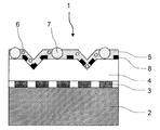
- FIG. 1 is a cross-sectional view showing an example of a decorative sheet according to the first embodiment of the present invention.
- a decorative sheet 1 shown in FIG. 1 has a pattern layer 3, a transparent resin layer 4, and a surface protective layer 5 laminated on a base sheet 2.
- the surface protective layer 5 contains fine particles A6 having a particle diameter equal to or smaller than the thickness of the surface protective layer 5 and fine particles B7 having a particle diameter larger than the thickness of the surface protective layer.
- the base sheet is a layer in which a pattern layer or the like is sequentially laminated on the surface (front surface).
- the base sheet contains a non-halogen thermoplastic resin.
- Non-halogen thermoplastic resins include low density polyethylene (including linear low density polyethylene), medium density polyethylene, high density polyethylene, ethylene ⁇ -olefin copolymer, homopolypropylene, polymethylpentene, polybutene, and ethylene-propylene.
- Olefin-based thermoplastics such as copolymers, propylene-butene copolymers, ethylene-vinyl acetate copolymers, saponified ethylene-vinyl acetate copolymers, or mixtures thereof, polyethylene terephthalate, polybutylene terephthalate, polyethylene Thermoplastic ester resins such as naphthalate, polyethylene naphthalate-isophthalate copolymer, polycarbonate, polyarylate, polymethyl methacrylate, polyethyl methacrylate, polyethyl acrylate, polyacrylate Thermoplastic acrylic resins such as butyl, nylon-6, polyamide-based thermoplastic resin such as nylon-66, or, polyimide, polyurethane, polystyrene, acrylonitrile - butadiene - styrene resin. Further, these non-halogen thermoplastic resins may be used alone or in combination of two or more. Of these, olef
- the base sheet may be colored.
- a coloring material pigment or dye
- a coloring material for example, inorganic pigments such as titanium dioxide, carbon black and iron oxide, organic pigments such as phthalocyanine blue, and various dyes can be used. These can be selected from one or more known or commercially available ones. Further, the addition amount of the colorant may be appropriately set according to the desired color tone.
- the base sheet contains various additives such as fillers, matting agents, foaming agents, flame retardants, lubricants, antistatic agents, antioxidants, UV absorbers, and light stabilizers as necessary. It may be.
- the thickness of the base sheet is 180 to 350 ⁇ m.
- the thickness of the base sheet is less than 180 ⁇ m, the unevenness of the adherend cannot be sufficiently prevented from appearing on the decorative board surface.
- the thickness of a base material sheet exceeds 350 micrometers, roll lamination will become difficult by winding up when a decorative sheet is preserve
- the thickness of the substrate sheet can be appropriately set depending on the use of the final product, the method of use, etc., as long as it is within the above range, but is preferably 180 to 310 ⁇ m.
- a region having a Martens hardness of 50 N / mm 2 or more exists with a thickness of 120 ⁇ m or more from the surface of the substrate sheet on the side opposite to the design pattern layer side.
- the region having a Martens hardness of 50 N / mm 2 or more is preferably present in a thickness of 120 to 250 ⁇ m from the surface opposite to the surface on the pattern layer side of the base sheet.
- the substrate sheet has a Martens hardness of 50 N / mm 2 or more in a region existing at a thickness of 120 ⁇ m or more from the surface opposite to the surface on the pattern layer side of the substrate sheet.
- the Martens hardness is a value measured using a surface film property testing machine (PICODERTOR HM-500, manufactured by Fisher Instruments Co., Ltd.), and a specific measuring method is as follows. .
- the diamond indenter (Vickers indenter) shown in FIG. 2 (a)
- the diamond indenter is pushed into the measurement sample as shown in FIG. 2 (b), and the diagonal line of the pyramidal depression formed on the surface is obtained.
- the surface area A (mm 2 ) is calculated from the length of and the hardness is obtained by dividing the test load F (N).
- the indentation conditions were as follows.
- the Martens hardness of the cross section of a base material sheet was measured.
- the decorative sheet is embedded with a resin (cold-curing type epoxy two-component curable resin), allowed to stand for 24 hours or more at room temperature and cured, and then the cured embedded sample is mechanically polished to form a base sheet. The cross section was exposed, and the Martens hardness of the cross section was measured by pushing a diamond indenter into the cross section.
- the Martens hardness of the substrate sheet can be appropriately set by 1) mixing a plurality of resin components, 2) adding an elastomer to the resin, or the like.
- the base sheet has a total thickness of 180 to 350 ⁇ m, and an area with a Martens hardness of 50 N / mm 2 or more exists with a thickness of 120 ⁇ m or more from the surface opposite to the pattern layer side of the base sheet. If it is, it may be a single layer or a plurality of layers.
- a layer having a Martens hardness of 50 N / mm 2 or more on the surface opposite to the surface on the pattern layer side of the decorative sheet is a single layer.
- a layer having a thickness of 120 ⁇ m or more and a layer having a Martens hardness of less than 50 N / mm 2 may be laminated on the surface of the layer on the pattern side.
- the layer having a Martens hardness of 50 N / mm 2 or more may have a configuration in which a thickness of 120 ⁇ m or more is obtained by laminating a plurality of layers showing the Martens hardness.
- the base sheet is a single layer, if a region having a Martens hardness of 50 N / mm 2 or more exists at a thickness of 120 ⁇ m or more from the surface opposite to the surface on the pattern layer side of the base sheet.
- the area on the pattern layer side may be configured to include an area where the Martens hardness gradually decreases and becomes less than 50 N / mm 2 .
- the base sheet may be subjected to corona discharge treatment on the surface (front surface) in order to enhance the adhesion of the ink forming the pattern layer.
- corona discharge treatment on the surface (front surface) in order to enhance the adhesion of the ink forming the pattern layer.
- What is necessary is just to implement the method and conditions of a corona discharge process according to a well-known method.
- Pattern pattern layer is a layer that imparts a desired pattern (design) to the decorative sheet, and the type of pattern is not limited. For example, a wood grain pattern, a leather pattern, a stone pattern, a grain pattern, a tiled pattern, a brickwork pattern, a cloth pattern, a geometric figure, a character, a symbol, an abstract pattern, and the like can be given.
- the method for forming the pattern layer is not particularly limited.
- an ink obtained by dissolving (or dispersing) a known colorant (dye or pigment) in a solvent (or dispersion medium) together with a binder resin is used. What is necessary is just to form on the base-material sheet
- an aqueous composition can be used from the viewpoint of reducing the VOC of the decorative sheet.
- the colorant examples include inorganic pigments such as carbon black, titanium white, zinc white, dial, bitumen, and cadmium red; azo pigments, lake pigments, anthraquinone pigments, quinacridone pigments, phthalocyanine pigments, isoindolinone pigments, dioxazine pigments.
- Organic pigments such as aluminum powder, metal powder pigments such as bronze powder, pearlescent pigments such as titanium oxide-coated mica and bismuth oxide chloride; fluorescent pigments; These colorants can be used alone or in admixture of two or more. These colorants may be used together with fillers such as silica, extender pigments such as organic beads, neutralizing agents, surfactants and the like.
- binder resin in addition to polyester-based urethane resin treated with hydrophilicity, polyester, polyacrylate, polyvinyl acetate, polybutadiene, polyvinyl chloride, chlorinated polypropylene, polyethylene, polystyrene, polystyrene-acrylate copolymer, rosin derivative
- an alcohol adduct of styrene-maleic anhydride copolymer, cellulose resin and the like can be used in combination. More specifically, for example, polyacrylamide resins, poly (meth) acrylic resins, polyethylene oxide resins, poly N-vinyl pyrrolidone resins, water-soluble polyester resins, water-soluble polyamide resins, water-soluble amino acids.
- water-based resins water-soluble phenolic resins, other water-soluble synthetic resins; water-soluble natural polymers such as polynucleotides, polypeptides, polysaccharides, and the like.
- water-soluble natural polymers such as polynucleotides, polypeptides, polysaccharides, and the like.
- natural rubber, synthetic rubber, polyvinyl acetate resin, (meth) acrylic resin, polyvinyl chloride resin, polyurethane-polyacrylic resin, etc. modified or a mixture of natural rubber, etc. Resin can also be used.
- the said binder resin can be used individually or in combination of 2 or more types.
- the solvent examples include petroleum organic solvents such as hexane, heptane, octane, toluene, xylene, ethylbenzene, cyclohexane, and methylcyclohexane; ethyl acetate, butyl acetate, acetic acid-2-methoxyethyl, acetic acid-2 -Ester-based organic solvents such as ethoxyethyl; alcohol-based organic solvents such as methyl alcohol, ethyl alcohol, normal propyl alcohol, isopropyl alcohol, isobutyl alcohol, ethylene glycol, propylene glycol; ketones such as acetone, methyl ethyl ketone, methyl isobutyl ketone, cyclohexanone Organic solvents; ether organic solvents such as diethyl ether, dioxane, tetrahydrofuran; dichloromethane
- Examples of the printing method used for forming the pattern layer include a gravure printing method, an offset printing method, a screen printing method, a flexographic printing method, an electrostatic printing method, and an inkjet printing method.
- a gravure printing method for example, roll coating method, knife coating method, air knife coating method, die coating method, lip coating method, comma coating method, kiss coating method, flow coating method, dip coating
- Various coating methods such as a coating method may be mentioned.
- the hand-drawn method, the ink-sink method, the photographic method, the transfer method, the laser beam drawing method, the electron beam drawing method, the metal partial evaporation method, the etching method, etc. may be used or combined with other forming methods. Good.
- the thickness of the pattern layer is not particularly limited and can be appropriately set according to the product characteristics.
- the layer thickness at the time of coating is about 1 to 15 ⁇ m, and the layer thickness after drying is about 0.1 to 10 ⁇ m.
- the transparent resin layer is not particularly limited as long as it is transparent, and includes any of colorless and transparent, colored and transparent, and translucent.
- the transparent resin layer contains a non-halogen thermoplastic resin.
- Non-halogen thermoplastic resins include low density polyethylene (including linear low density polyethylene), medium density polyethylene, high density polyethylene, ethylene ⁇ -olefin copolymer, homopolypropylene, polymethylpentene, polybutene, and ethylene-propylene.
- Olefin-based thermoplastics such as copolymers, propylene-butene copolymers, ethylene-vinyl acetate copolymers, saponified ethylene-vinyl acetate copolymers, or mixtures thereof, polyethylene terephthalate, polybutylene terephthalate, polyethylene Thermoplastic ester resins such as naphthalate, polyethylene naphthalate-isophthalate copolymer, polycarbonate, polyarylate, polymethyl methacrylate, polyethyl methacrylate, polyethyl acrylate, polyacrylate Thermoplastic acrylic resins such as butyl, nylon-6, polyamide-based thermoplastic resin such as nylon-66, or, polyimide, polyurethane, polystyrene, acrylonitrile - butadiene - styrene resin. Further, these non-halogen thermoplastic resins may be used alone or in combination of two or more. Of these, olef
- the transparent resin layer may be colored as long as it has transparency, but it is particularly desirable not to add a colorant.
- Martens hardness of the transparent resin layer is preferably 20 ⁇ 40N / mm 2, more preferably 30 ⁇ 40N / mm 2. If the Martens hardness of the transparent resin layer is too high, the decorative sheet may be inferior in curling resistance, and if it is too low, the decorative sheet and the adherend are laminated to form a decorative board. The uneven shape may be easily exposed on the surface of the decorative board.
- the thickness of the transparent resin layer is preferably about 20 to 200 ⁇ m, more preferably 80 to 100 ⁇ m. The above range may be exceeded depending on the use of the decorative sheet.
- the decorative sheet of the present invention has a surface protective layer formed on the surface.
- the thickness of the surface protective layer of the decorative sheet of the present invention is 7 to 30 ⁇ m.
- the thickness of the surface protective layer is less than 7 ⁇ m, it becomes difficult to shape the embossed shape, resulting in poor design.
- the thickness of the surface protective layer is less than 7 ⁇ m, the embossed shape is not sufficiently formed, so that the load at the time of rubbing the surface of the decorative sheet is difficult to disperse and the scratch resistance is poor.
- the thickness of the surface protective layer exceeds 30 ⁇ m, the decorative sheet is wound when stored in a roll state, and roll lamination becomes difficult.
- the thickness of the surface protective layer is preferably 10 to 20 ⁇ m.
- the surface protective layer is formed adjacent to the gloss adjusting layer. Specifically, the back surface and / or the side surface of the surface protective layer are adjacent to the gloss adjusting layer.
- the surface protective layer is preferably transparent.
- the surface protective layer contains fine particles A having a particle diameter equal to or smaller than the thickness of the surface protective layer, and fine particles B having a particle diameter larger than the thickness of the surface protective layer.
- SEM scanning electron microscope
- the particle diameter of the fine particles A is equal to or smaller than the thickness of the surface protective layer and that the particle diameter of the fine particles B is larger than the thickness of the surface protective layer.
- the particle diameter of the fine particles A is not particularly limited as long as it is equal to or less than the thickness of the surface protective layer.
- the particle diameter of the fine particles A exceeds the thickness of the surface protective layer, the matting effect is not sufficient, and the fine particles A cue from the surface protective layer and cue from the surface protective layer of the fine particles A.
- the rubbed part is rubbed and scraped, the gloss of the rubbed part is raised and noticeable, and the scratch resistance is not sufficient.
- the particle size of the fine particles A is preferably 3 to 15 ⁇ m, more preferably 8 to 12 ⁇ m. If the particle diameter of the fine particles A is too small, the matting effect may not be sufficient.
- the content of the fine particles A is 5 to 30 parts by mass with respect to 100 parts by mass of the resin component of the surface protective layer. If the content of the fine particles A is too large, the fine particles A cued from the surface protective layer increase, and when the crushed portion is rubbed and scraped off, the gloss of the rubbed portions increases and becomes conspicuous. Not enough. Further, if the content of the fine particles A is too small, the matting effect is not sufficient.
- the content of the fine particles A is preferably 10 to 20 parts by mass with respect to 100 parts by mass of the resin component of the surface protective layer.
- the particle diameter of the fine particles B is not particularly limited as long as it is larger than the thickness of the surface protective layer. When the particle diameter of the fine particles B is equal to or smaller than the thickness of the surface protective layer, the surface protective layer has insufficient scratch resistance.
- the particle diameter of the fine particles B is preferably 8 to 33 ⁇ m, and more preferably 8 to 20 ⁇ m. If the particle diameter of the fine particles B is too large, the fine particles B may be easily detached from the surface protective layer.
- the content of the fine particles B is 5 to 30 parts by mass with respect to 100 parts by mass of the resin component of the surface protective layer. If the content of the fine particles B is too large, when the cueing portion of the fine particles B is rubbed and scraped, the gloss of the rubbed portions increases and becomes conspicuous, and the scratch resistance becomes insufficient. Moreover, when there is too little content of microparticles
- the content of the fine particles B is preferably 10 to 20 parts by mass with respect to 100 parts by mass of the resin component of the surface protective layer.
- the particle diameters of the fine particles A and B can be measured by SEM (scanning electron microscope). For example, a decorative sheet is cut in a direction perpendicular to the surface, and the surface of the obtained cross section is obtained. It can be measured by photographing an arbitrary portion of the protective layer using an SEM (scanning electron microscope) and averaging the particle diameter of the fine particles A and the particle diameter (diameter) of the fine particles B, respectively.
- SEM scanning electron microscope
- the total content of the fine particles A and the fine particles B is 15 to 35 parts by mass with respect to 100 parts by mass of the resin component of the surface protective layer. If the total content of the fine particles A and the total content of the fine particles B is too small, the surface protective layer is inferior in scratch resistance and design (low glossiness), and if the total content is too large, the fine particles A and B When the part is rubbed and scraped off, the gloss of the rubbed part increases and becomes conspicuous, resulting in insufficient scratch resistance.
- the total content of the fine particles A and the fine particles B is preferably 20 to 35 parts by mass with respect to 100 parts by mass of the resin component of the surface protective layer.
- the fine particles A and B are not particularly limited as long as they can impart scratch resistance to the surface protective layer according to the particle size and can exhibit a matting effect, and conventionally known particles can be used.
- the fine particles A and B include inorganic particles such as silica fine particles and silicone resins; organic particles such as crosslinked alkyl, crosslinked styrene, inzoguanamine resin, urea-formaldehyde resin, phenol resin, polyethylene, and nylon. .
- silica fine particles are preferable.
- the resin component contained in the surface protective layer is not limited, but preferably contains an ionizing radiation curable resin or a two-component curable urethane resin. Substantially those formed from these resins are preferred.
- the surface protective layer is formed from an ionizing radiation curable resin or a two-component curable urethane resin, it is easy to improve the wear resistance, impact resistance, stain resistance, scratch resistance, weather resistance, etc. of the decorative sheet. Among these, ionizing radiation curable resins are more preferable.
- the ionizing radiation curable resin is not particularly limited, and prepolymers (including oligomers) and / or monomers containing radically polymerizable double bonds capable of undergoing a crosslinking reaction upon irradiation with ionizing radiation such as ultraviolet rays and electron beams.
- a transparent resin containing as a main component can be used. These prepolymers or monomers can be used alone or in combination.
- the curing reaction is usually a cross-linking curing reaction.
- a compound having in the molecule a radically polymerizable unsaturated group such as a (meth) acryloyl group or (meth) acryloyloxy group, or a cationically polymerizable functional group such as an epoxy group.
- a polyene / thiol prepolymer based on a combination of polyene and polythiol is also preferable.
- the (meth) acryloyl group means an acryloyl group or a methacryloyl group.
- Examples of the prepolymer having a radically polymerizable unsaturated group include polyester (meth) acrylate, urethane (meth) acrylate, epoxy (meth) acrylate, melamine (meth) acrylate, triazine (meth) acrylate, and silicone (meth) acrylate. Etc. These molecular weights are usually preferably about 250 to 100,000.
- Examples of the monomer having a radical polymerizable unsaturated group include, as monofunctional monomers, methyl (meth) acrylate, 2-ethylhexyl (meth) acrylate, phenoxyethyl (meth) acrylate, and the like.
- polyfunctional monomer examples include diethylene glycol di (meth) acrylate, propylene glycol di (meth) acrylate, trimethylolpropane tri (meth) acrylate, trimethylolpropane ethylene oxide tri (meth) acrylate, dipentaerythritol tetra ( And (meth) acrylate, dipentaerythritol penta (meth) acrylate, and dipentaerythritol hexa (meth) acrylate.
- Examples of the prepolymer having a cationically polymerizable functional group include prepolymers of epoxy resins such as bisphenol type epoxy resins and novolak type epoxy compounds, and vinyl ether type resins such as fatty acid type vinyl ethers and aromatic vinyl ethers.
- Examples of the thiol include polythiols such as trimethylolpropane trithioglycolate and pentaerythritol tetrathioglycolate.
- Examples of the polyene include those in which allyl alcohol is added to both ends of polyurethane by diol and diisocyanate.
- the ionizing radiation used for curing the ionizing radiation curable resin electromagnetic waves or charged particles having energy capable of causing a curing reaction of molecules in the ionizing radiation curable resin (composition) are used.
- electromagnetic waves or charged particles having energy capable of causing a curing reaction of molecules in the ionizing radiation curable resin (composition) are used.
- ultraviolet rays or electron beams may be used, but visible light, X-rays, ion rays, or the like may be used.
- the two-component curable urethane resin is not particularly limited.
- a polyol component (acrylic polyol, polyester polyol, polyether polyol, epoxy polyol, etc.) having an OH group as a main component and an isocyanate component (tolylene diene) which is a curing agent component.
- Isocyanate, hexamethylene diisocyanate, metaxylene diisocyanate and the like) can be used.
- the resins exemplified above can be used alone or in combination of two or more.
- a UV absorber such as benzotriazole, benzophenone, salicylate, or triazine
- a UV absorber such as benzotriazole, benzophenone, salicylate, or triazine
- photopolymerization initiators acetophenones, benzophenones, Michler benzoylbenzoate, ⁇ -aminoxime ester, tetramethylthiuram monosulfide, thioxanthones, aromatic diazonium salts
- n-butylamine, triethylamine, tri-n-butylphosphine and the like can be used as photopolymerization accelerators (sensitizers) such as aromatic sulfonium salts and metallocenes.
- an antibacterial agent may be added to the surface protective layer in order to impart antibacterial properties.
- Antibacterial agents include inorganic antibacterial agents and organic antibacterial agents.
- inorganic antibacterial agents are desirable because they are generally safer than organic antibacterial agents and are excellent in durability and heat resistance.
- Inorganic antibacterial agents are those in which antibacterial metals such as silver, copper and zinc are supported on various inorganic carriers.
- the addition amount of the antibacterial agent is preferably 0.1 to 10 parts by mass with respect to 100 parts by mass of the resin component.
- additives such as solvents, dyes and pigments, fillers such as extenders, antifoaming agents, leveling agents, and thixotropic agents can be added to the surface protective layer as necessary.
- the surface protective layer is, for example, after applying an ionizing radiation curable resin or a two-component curable urethane resin on a transparent resin layer or a gloss adjusting layer described later by a known coating method such as gravure coating, roll coating, It can be formed by curing the resin.
- the surface protective layer-forming resin composition is partially applied (for example, in a pattern), and then the surface protective layer is formed.
- the surface protective layer can be formed by curing the ionizing radiation curable resin in the resin composition.
- the surface protective layer-forming resin composition is applied over the entire surface, and then ionizing radiation in the resin composition.
- the surface protective layer can be formed by curing the curable resin.
- the gloss value of the surface protective layer can be adjusted by a method of selecting the type of each material such as a resin component and an additive contained in the surface protective layer; a method of appropriately setting the content of each of the above materials; .
- the decorative sheet of the first embodiment of the present invention has a specific configuration (layer configuration) as long as at least a pattern layer, a transparent resin layer, and a surface protective layer are laminated in this order on the base sheet. It is not limited.
- the direction in which the surface protective layer is laminated as viewed from the base sheet is referred to as “upper” or “front surface”, and the back primer layer as viewed from the base sheet is The direction in which the layers are stacked is referred to as “lower” or “back surface”.
- the “front surface (side)” or “surface of the surface protective layer (side)” of the decorative sheet or decorative plate means a surface that is visually recognized after the decorative sheet or decorative plate is applied.
- the layer sheet other than the base sheet, the pattern layer, the transparent resin layer, and the surface protective layer described above will be specifically described with the decorative sheet having such a layer configuration as a representative example.
- Transparent adhesive layer A transparent adhesive layer may be formed on the pattern layer in order to enhance the adhesion between the transparent resin layer and the pattern layer.
- the transparent adhesive layer is not particularly limited as long as it is transparent, and includes any of transparent and colorless, colored and translucent.
- the adhesive is not particularly limited, and an adhesive known in the field of decorative sheets can be used.
- known adhesives in the field of decorative sheets include thermoplastic resins such as polyamide resins, acrylic resins and vinyl acetate resins, and thermosetting resins such as urethane resins. These adhesives can be used individually by 1 type or in combination of 2 or more types. Further, a two-component curable polyurethane resin or polyester resin using isocyanate as a curing agent can also be applied.
- the thickness of the transparent adhesive layer is not particularly limited, but the thickness after drying is about 0.1 to 30 ⁇ m, preferably about 1 to 20 ⁇ m.
- a primer layer may be provided on the primer layer transparent resin layer.
- the primer layer can be formed by applying a known primer agent to the surface of the transparent resin layer.
- the primer agent include a urethane resin-based primer agent made of an acrylic-modified urethane resin (acrylic urethane resin), a urethane-cellulose resin (for example, a resin obtained by adding hexamethylene diisocyanate to a mixture of urethane and nitrified cotton) ), A resinous primer agent made of a block copolymer of acrylic and urethane, and the like. You may mix
- the additive examples include fillers such as calcium carbonate and clay, flame retardants such as magnesium hydroxide, antioxidants, lubricants, foaming agents, ultraviolet absorbers, and light stabilizers.
- the blending amount of the additive can be appropriately set according to the product characteristics.
- the application amount of the primer agent is not particularly limited, but is usually 0.1 to 100 g / m 2 , preferably about 0.1 to 50 g / m 2 .
- the thickness of the primer layer is not particularly limited, but is usually about 0.01 to 10 ⁇ m, preferably about 0.1 to 1 ⁇ m.
- a gloss control layer may be formed on the decorative sheet of the present invention.
- Examples of the form of the decorative sheet on which the gloss adjusting layer is formed include the forms shown in FIGS. 3 to 5.
- the gloss adjusting layer is formed on the transparent resin layer so as to be adjacent to the surface protective layer. More specifically, the back surface of the gloss adjusting layer is adjacent to the front surface of the transparent resin layer (or the primer layer when the decorative sheet of the present invention has the primer layer), and The front surface and / or the side surface of the gloss adjusting layer is adjacent to the surface protective layer.
- the gloss adjustment layer may be formed on a part of the surface on the front surface side (the surface side visually recognized after the decorative sheet or decorative plate is applied) from the viewpoint of design, and (2 ) It may be formed on the entire front surface (entire surface). That is, the gloss adjustment layer may be (1) partially formed with respect to the front surface, and (2) formed over the entire surface with respect to the front surface. May be.
- the surface protective layer may be formed on a part of the front surface
- the surface protective layer may be formed on the entire front surface side.
- the surface protective layer is formed by the gloss adjusting layer. It is formed so as to fill a region that has not been formed (region that does not exist).
- the gloss adjusting layer is formed on a part of the front side surface, and the surface protective layer is formed on the entire front side ((1) ( b)).
- the gloss adjusting layer is formed on a part of the front side surface, and the surface protective layer is formed on a part of the front side surface ((1) above). (Form of (a)).
- the surface protective layer is formed on a part of the front surface.
- the gloss adjusting layer is formed on the entire front surface side, and the surface protective layer is formed on a part of the front surface side (form (2) above. ).
- the gloss value of the gloss adjusting layer is G A
- the gloss value of the surface protective layer is GP .
- the relationship between the gloss values G A luster control layer and the luster value G P of the aforementioned surface protective layer is a G P ⁇ G A.
- the G P and the G A in the present specification is a value measured according to Japanese Industrial Standard JIS Z8741.
- the gloss value is also referred to as a gloss value or a gloss value.
- the gloss adjustment layer is formed on a part of the front surface side, or (2) the gloss adjustment layer is formed on the entire front surface side, Even so, both the gloss adjusting layer and the surface protective layer are visually recognized on the surface visually recognized after the decorative sheet or decorative plate is applied, and the gloss values of the gloss adjusting layer and the surface protective layer are the same. relationship is G P ⁇ G a. Therefore, when the decorative sheet of the present invention is attached to the adherend, the influence of the uneven shape (duck) generated on the decorative sheet surface is further suppressed, and the design of the decorative sheet or decorative plate is improved. Therefore, the decorative sheet of the present invention in which the gloss adjusting layer is formed is a preferred embodiment as the present invention.
- the area ratio of the region where the gloss adjusting layer occupies per 1 cm 2 of the front surface area of the decorative sheet or decorative plate is preferably 20 to 80%.
- the gloss adjusting layer is formed so that the front surface (surface to be visually recognized) side of the gloss adjusting layer has a pattern shape.
- the gloss adjusting layer has a pattern shape and the ratio of the area is 20 to 80%, the gloss difference between the gloss adjusting layer and the surface protective layer becomes clearer, and as a result, the design is further improved, and The influence of the uneven shape can be further suppressed.
- the type of the pattern is not particularly limited. Specific examples of the pattern include those similar to the various patterns exemplified in the pattern pattern layer described above.
- the ratio of the area of the gloss adjusting layer (area where the gloss adjusting layer is present) occupying per 1 cm 2 of the front surface area of the decorative sheet or decorative plate is defined as the ratio of the gloss adjusting layer. It may be called an occupied area ratio.
- the occupation area ratio of the gloss adjusting layer is calculated from plate-making data at the stage of producing a plate for forming the gloss adjusting layer.
- the occupied area ratio of the gloss adjusting layer can be calculated from the shape of the plate.
- G A and the G P are G A ⁇ G P is preferred. More preferably, G A ⁇ GP and G A ⁇ 5.
- the surface protective layer is formed on a part of the surface on the front surface side.
- the surface protective layer is formed so that the front surface (surface to be visually recognized) side of the surface protective layer has a pattern shape.
- the gloss difference between the gloss adjusting layer and the surface protective layer becomes clearer, and as a result, the design property can be further improved and the influence of the uneven shape can be further suppressed.
- the type of the pattern is not particularly limited. Specific examples of the pattern include those similar to the various patterns exemplified in the pattern pattern layer described above.
- is preferably ⁇ 2
- the relationship between the G A and the G P may be a G A ⁇ G P, or may be a G P ⁇ G A.
- the surface protective layer of the luster control layer may be a low gloss than it is the surface protective layer of the luster control layer, also towards the surface protective layer may be a low glossy than luster control layer (Incidentally, are G A ⁇ G P If a layer of the luster control layer is low luster, if a G P ⁇ G a surface protective layer is a layer of low gloss). In the case of (2), it is preferable that the ratio of the area of the region where the low-gloss layer occupies per 1 cm 2 of the front surface area of the decorative sheet or the decorative plate exceeds 50%.
- the ratio of the area of the surface protective layer (area where the surface protective layer is present) occupying per 1 cm 2 of the front surface area of the decorative sheet or decorative plate is defined as the surface protective layer It may be called an occupied area ratio.
- the occupation area ratio of the surface protective layer is calculated from plate-making data at the stage of producing a plate for forming the surface protective layer.
- the occupation area ratio of the surface protective layer can also be calculated from the shape of the plate.
- the ratio of the area where the low-gloss layer is exposed per 1 cm 2 of the front surface area of the decorative sheet or plate is (i) low
- the occupied area ratio of the surface protective layer is directly the occupied area ratio of the low gloss layer
- the low gloss layer is a gloss adjustment layer
- After calculating the occupation area ratio of the surface protective layer it is obtained by subtracting (minus) the occupation area ratio of the surface protection layer from 100 (%).
- the method for forming the gloss adjusting layer is not particularly limited.
- it is dissolved (or dispersed) in a solvent (or dispersion medium) together with known colorants (dyes, pigments, etc.) and vehicles. It can form with the ink obtained.
- a coloring agent and a solvent the thing similar to the coloring agent and solvent which were illustrated by the coloring agent and solvent in the above-mentioned pattern pattern layer, respectively can be used.
- the ink vehicle for forming the gloss adjusting layer preferably contains 50% by mass or more of urethane resin and / or polyvinyl acetal resin.
- the urethane resin is a polyol component such as an acrylic polyol, a polyester polyol, or a polyether polyol, and an isocyanate component such as tolylene diisocyanate, xylene diisocyanate, diphenylmethane diisocyanate, or the like, isophorone diisocyanate, hexamethylene diisocyanate, Examples include urethane resins obtained by reacting with aliphatic or cycloaliphatic isocyanates such as hydrogenated tolylene diisocyanate (linearly cross-linked or network cross-linked).
- a polyvinyl acetal type resin is obtained by condensation (acetalization) of polyvinyl alcohol and aldehydes.
- the polyvinyl acetal resin include polyvinyl formal (formal resin), polyvinyl acetoacetal, polyvinyl propional, polyvinyl butyral (butyral resin), and polyvinyl hexyl.
- polyvinyl butyral is particularly preferable because it is soluble in a solvent, easily converted into an ink, and has a good appearance of visual unevenness (recognized visually as a recess).
- gloss adjusting resins such as unsaturated polyester resins, acrylic resins, and vinyl chloride-vinyl acetate copolymers may be mixed to adjust the gloss value.
- the mixing ratio is preferably in the range of 10 to 50% by mass with respect to the total amount of the vehicle.
- the ink for forming the gloss adjusting layer may be uncolored or may be colored by adding a colorant such as a pigment.
- an extender pigment may be blended in the ink for forming the gloss adjusting layer.
- the extender pigment is not particularly limited, and is suitably selected from, for example, silica, talc, clay, barium sulfate, barium carbonate, calcium sulfate, calcium carbonate, magnesium carbonate and the like.
- silica which is a material having a high degree of freedom in material design such as oil absorption, particle size, pore volume, etc., and excellent in designability, whiteness, and coating stability as an ink, is preferable.
- Silica is preferred.
- its content is preferably 5 to 15 parts by mass with respect to 100 parts by mass of ink (ink composition) other than the extender.
- Gloss values G A luster control layer, vehicle described above, luster control resin, a method for selecting a type of each substance and coloring agent (including extender pigments); and the like; how to set the contents of the above materials properly Can be adjusted.
- the printing method used for forming the gloss adjusting layer for example, the gravure printing method, the offset printing method, the screen printing method, the flexographic printing method, the electrostatic printing method, the inkjet method, and the like, as in the printing method used for forming the above-mentioned pattern pattern layer.
- the printing method etc. are mentioned.
- the method similar to the various coating methods in formation of a pattern layer is mentioned.
- the gloss adjusting layer is preferably formed so as to have a pattern shape.
- the gloss adjusting layer is more preferably formed in a pattern such as a dot shape, a lattice shape, or a wood grain conduit pattern (shape). Since the gloss adjustment layer is formed in the above pattern, the gloss of the area with the gloss adjustment layer is further different from the gloss of the area other than the gloss adjustment layer (area without the gloss adjustment layer). An optical illusion appears as if there is a recess, and it is visually recognized as a unique stereoscopic effect. For this reason, the uneven shape (duck) becomes less noticeable.
- the gloss adjusting layer so as to be interlocked (tuned) with the pattern of the pattern pattern layer.
- the pattern layer is formed in a wood grain pattern
- a decorative sheet having a more excellent design can be obtained by printing the pattern in a wood conduit pattern to form a gloss adjusting layer.
- the thickness (film thickness) of the gloss adjusting layer is preferably 0.5 ⁇ m to 5 ⁇ m in consideration of printability and interaction with the resin composition for forming the surface protective layer.
- a back primer layer may be provided on the back surface of the back primer layer substrate sheet (the surface opposite to the surface on which the pattern layer is laminated). For example, it is effective when a decorative sheet is produced by bonding a base sheet and an adherend.
- the back primer layer can be formed by applying a known primer to the base material sheet.
- the primer agent include a urethane resin-based primer agent made of an acrylic-modified urethane resin (acrylic urethane resin), a urethane-cellulose resin (for example, a resin obtained by adding hexamethylene diisocyanate to a mixture of urethane and nitrified cotton) ), A resinous primer agent made of a block copolymer of acrylic and urethane, and the like. You may mix
- the additive examples include fillers such as calcium carbonate and clay, flame retardants such as magnesium hydroxide, antioxidants, lubricants, foaming agents, ultraviolet absorbers, and light stabilizers.
- the blending amount of the additive can be appropriately set according to the product characteristics.
- the application amount of the primer agent is not particularly limited, but is usually 0.1 to 100 g / m 2 , preferably about 0.1 to 50 g / m 2 .
- the thickness of the back primer layer is not particularly limited, but is usually about 0.01 to 10 ⁇ m, preferably about 0.1 to 1 ⁇ m.
- the decorative sheet of the first embodiment of the present invention is embossed from the surface protective layer side.
- the embossing method is not particularly limited. For example, a method of heating and softening the front surface of the surface protective layer, pressurizing and shaping with an embossing plate, and cooling is preferable.
- the front surface of the transparent resin layer or the gloss adjusting layer is heated and softened, and after pressing and shaping with an embossed plate, a surface protective layer is formed thereon. Also good.
- a known single-wafer or rotary embossing machine is used.
- the concavo-convex shape include a wood grain plate conduit groove, a stone plate surface unevenness (such as granite cleaved surface), a cloth surface texture, a satin texture, a grain, a hairline, a ridge line, and the like.
- the ten-point average roughness Rz jis of the surface of the decorative sheet is preferably 60 ⁇ m or more, and more preferably 70 ⁇ m or more.
- the ten-point average roughness Rz jis of the surface of the decorative sheet is preferably 150 ⁇ m or less, and more preferably 120 ⁇ m or less.
- the ten-point average roughness Rz jis can be adjusted to the above-described range, and thereby, the scratch resistance and design properties are more excellent. It can be used as a decorative sheet.
- the ten-point average roughness Rz jis in the first embodiment is a value measured by a measuring method based on JIS B0601-2001.
- the decorative sheet of the present invention has a surface 60 ° gloss (gloss value (incident angle 60 °)) of preferably 14 or less, and more preferably 10 or less.
- the 60 ° gloss on the surface of the decorative sheet is not particularly limited, but is preferably 3 or more.
- the 60 ° gloss is applied to a decorative sheet using a gloss meter (trade name: GMX-202, manufactured by Murakami Color Research Laboratory Co., Ltd.) according to a method in accordance with Japanese Industrial Standard JISZ-8741. It is a value measured by measuring along the direction. Further, 60 ° gloss of the decorative sheet surface of the present invention, the same as G A and the G P, can be measured using a Nippon Denshoku Industries Co., Ltd. PG-3D.
- Decorative plate A decorative sheet can be obtained by laminating the decorative sheet of the present invention on an adherend.
- the decorative board of the present invention is obtained by laminating the decorative sheet of the present invention on an adherend so that the surface protective layer of the decorative sheet of the present invention becomes the outermost surface layer.
- the adherend is not limited, and the same materials as those used for known decorative panels can be used.
- the adherend include wood materials, metals, ceramics, plastics, and glass.
- the decorative sheet of the present invention can be suitably used for a wood material.
- wood materials include veneer, wood veneer, wood plywood, particle board, medium density fiberboard (MDF) made from various materials such as cedar, firewood, firewood, pine, lawan, teak, and melapie. , Chip boards, or composite substrates on which chip boards are laminated.
- MDF medium density fiberboard
- Chip boards, or composite substrates on which chip boards are laminated As the wood material, it is preferable to use a chip board or a composite base material on which chip boards are laminated.
- the lamination method of laminating the decorative sheet and the adherend is not limited, and for example, a method of sticking the decorative sheet to the adherend with an adhesive can be employed. What is necessary is just to select an adhesive agent suitably from well-known adhesive agents according to the kind etc. of to-be-adhered material. Examples thereof include polyvinyl acetate, polyvinyl chloride, vinyl chloride / vinyl acetate copolymer, ethylene / acrylic acid copolymer, ionomer, butadiene / acrylonitrile rubber, neoprene rubber, natural rubber and the like. These adhesives are used alone or in combination of two or more.
- the decorative board manufactured in this way includes, for example, interior materials for buildings such as walls, ceilings, and floors; exterior materials such as balconies and verandas; surface decorative boards and furniture for furniture such as window frames, doors, and handrails; Alternatively, it can be used for a surface decorative plate of a cabinet such as a light electric or OA device. In particular, the decorative board can be suitably used as a floor decorative material.
- a decorative sheet (1) Ten-point average roughness Rz jis of the surface of the decorative sheet is 40 ⁇ m or more, (2)
- the surface protective layer contains an ionizing radiation curable resin, (3)
- the base sheet, the transparent resin layer, and the backer layer each include a non-halogen thermoplastic resin, (4)
- the backer layer has a thickness of 120 to 250 ⁇ m, (5)
- the Martens hardness of the backer layer is 50 to 80 N / mm 2 , (6)
- the backer layer is laminated by extruding the backer layer forming resin composition in a molten state with respect to the back surface of the base sheet. It is characterized by that.
- the surface roughness of the decorative sheet is in a specific range
- the base sheet, the transparent resin layer, and the surface protective layer each contain a specific resin.
- a specific backer layer is laminated by extrusion (that is, when all the requirements (1) to (6) are satisfied)
- (a) Can be used in Europe and other countries where regulations on vinyl chloride resins are advancing.
- (b) When a decorative board is obtained by bonding to an adherend such as chipboard, the uneven shape of the adherend is suppressed from appearing on the surface of the decorative board (the uneven shape of the adherend).
- the decorative sheet according to the second embodiment of the present invention at least a transparent resin layer and a surface protective layer are sequentially laminated on a base material sheet, and at least a backer layer is laminated on the back surface of the base material sheet.
- the layer structure and the resin component constituting each layer are not particularly limited.
- a colored hiding layer, a pattern layer, a transparent adhesive layer, a transparent resin layer, a primer layer, and a surface protective layer are sequentially laminated on the base sheet, and the base sheet
- the base sheet A decorative sheet in which a backer layer and a back primer layer are laminated in order on the back surface of the sheet (note that the decorative sheet includes a backer layer, a base sheet, a colored hiding layer, a pattern layer, and transparency on the back primer layer. It can also be said that the adhesive layer, the transparent resin layer, the primer layer, and the surface protective layer are laminated in this order).
- the direction in which the surface protective layer is laminated as viewed from the base sheet is referred to as “up” or “front surface”, and the backer is viewed from the base sheet.
- the direction in which the layers are stacked is referred to as “bottom” or “back surface”.
- the “front surface (side)” or “surface of the surface protective layer (side)” of the decorative sheet or decorative plate means a surface that is visually recognized after the decorative sheet or decorative plate is applied.
- the decorative sheet of the second embodiment of the present invention has a base sheet.
- the base sheet contains a non-halogen thermoplastic resin.
- the resin component which comprises a base material sheet is a non-halogen-type thermoplastic resin.
- non-halogen thermoplastic resin As the non-halogen thermoplastic resin, the colorant, and the additive used for the base sheet of the second embodiment, the same ones as described above in the first embodiment can be used.
- the details of the corona discharge treatment of the base sheet of the second embodiment are also the same as in the first embodiment.
- the thickness of the base sheet is not particularly limited, but is preferably 50 to 100 ⁇ m.
- the thickness of the base sheet is within the above range, the unevenness appearing on the surface of the decorative board due to the uneven shape of the adherend can be further suppressed, and further curling is prevented when the decorative sheet is stored in a roll state. Thus, roll lamination can be performed more appropriately.
- the decorative sheet according to the second embodiment of the present invention has a backer layer on the back side of the base sheet.
- the backer layer means a buffer layer for the purpose of shock absorption or the like in the decorative sheet (and the decorative board).
- the backer layer contains a non-halogen thermoplastic resin.
- the resin component which comprises a backer layer is a non-halogen-type thermoplastic resin.
- the non-halogen thermoplastic resin includes the same resins as those exemplified for the base sheet. In addition, you may use a non-halogen-type thermoplastic resin individually or in mixture of 2 or more types. Among the non-halogen thermoplastic resins, olefin thermoplastic resins are preferable.
- the backer layer may be colored similarly to the base sheet.
- a coloring method the same method as the coloring method by a base material sheet is mentioned.
- the backer layer has various additives (fillers, matting agents, foaming agents, flame retardants, lubricants, antistatic agents, antioxidants, ultraviolet absorbers, light stabilizers, etc.) as with the base sheet. It may be included.
- the backer layer is laminated by extruding the backer layer forming resin composition in a molten state on the back surface of the base sheet.
- a resin component eg, non-halogen thermoplastic resin
- the backer layer is laminated by the above extrusion molding, even if a recess is formed on the back surface of the base sheet by embossing or the like, air does not enter the concave portion, and the back surface is laminated with good adhesion.
- the “molten state” means a state that can be molded by “extrusion molding” described later.
- extrusion molding a known extrusion molding method can be employed.
- extrusion molding using a T-die extruder, a cylindrical extruder, or the like can be given.
- T die include a multi-manifold type and a feed block type.
- the thickness of the backer layer is 120 to 250 ⁇ m.
- the thickness of the backer layer can be appropriately set depending on the use of the final product, the method of use, etc., as long as it is within the above range, but is preferably 120 to 180 ⁇ m.
- the Martens hardness of the backer layer is 50 to 80 N / mm 2 . If the Martens hardness of the backer layer is less than 50 N / mm 2 , the unevenness of the adherend cannot be suppressed to the surface of the decorative board. Moreover, when the Martens hardness of a backer layer exceeds 80 N / mm ⁇ 2 >, when a decorative sheet is preserve
- the Martens hardness of the backer layer can be appropriately set by 1) selecting a resin component as appropriate, 2) mixing a plurality of resin components, or 3) adding an elastomer to the resin.
- the backing layer can be subjected to known easy adhesion treatment such as corona discharge treatment, plasma treatment, degreasing treatment, surface roughening treatment, etc. on the adhesion surface.
- a primer layer back surface primer layer
- back surface primer layer may be further provided on the back surface of the backer layer.
- the back primer layer can be formed by applying a known primer agent to the backer layer.
- the primer agent include a urethane resin-based primer agent made of an acrylic-modified urethane resin (acrylic urethane resin), a urethane-cellulose resin (for example, a resin obtained by adding hexamethylene diisocyanate to a mixture of urethane and nitrified cotton) ), A resinous primer agent made of a block copolymer of acrylic and urethane, and the like. You may mix
- the additive examples include fillers such as calcium carbonate and clay, flame retardants such as magnesium hydroxide, antioxidants, lubricants, foaming agents, ultraviolet absorbers, and light stabilizers.
- the blending amount of the additive can be appropriately set according to the product characteristics.
- the application amount of the primer agent is not particularly limited, but is usually 0.1 to 100 g / m 2 , preferably about 0.1 to 50 g / m 2 .
- the thickness of the back primer layer is not particularly limited, but is usually about 0.01 to 10 ⁇ m, preferably about 0.1 to 1 ⁇ m.
- the decorative sheet according to the second embodiment of the present invention may have a pattern pattern layer on the base sheet.
- the details of the pattern layer of the decorative sheet of the second embodiment are the same as those of the pattern layer described above in the first embodiment.
- a colored concealment layer may be further formed between the colored concealment layer base sheet and the pattern layer, if necessary.
- the colored concealment layer is provided when it is desired to conceal the ground color of an adherend such as a wooden base material from the front surface of the decorative sheet.
- an adherend such as a wooden base material from the front surface of the decorative sheet.
- the base sheet is transparent, even when the base sheet is concealed, it may be formed to stabilize the concealment.
- an ink for forming a pattern layer and capable of masking coloring can be used as the ink for forming the colored masking layer.
- the method for forming the colored concealment layer is preferably a method that can be formed so as to cover the entire base sheet (solid form).
- the roll coating method, knife coating method, air knife coating method, die coating method, lip coating method, comma coating method, kiss coating method, flow coating method, dip coating method and the like described above are preferable.
- the thickness of the colored hiding layer is not particularly limited and can be appropriately set according to the product characteristics.
- the thickness at the time of coating is about 0.2 to 10 ⁇ m, and the thickness after drying is about 0.1 to 5 ⁇ m.
- Transparent adhesive layer A transparent adhesive layer may be formed on the pattern layer in order to enhance the adhesion between the transparent resin layer and the pattern layer.
- the details of the transparent adhesive layer of the decorative sheet of the second embodiment are the same as those of the transparent adhesive layer described above in the first embodiment.
- the decorative sheet according to the second embodiment of the present invention has a transparent resin layer on a base sheet.
- the details of the transparent resin layer of the decorative sheet of the second embodiment are the same as those of the transparent resin layer described above in the first embodiment.
- the thickness of the transparent resin layer is preferably about 20 to 200 ⁇ m, and more preferably 80 to 120 ⁇ m. The above range may be exceeded depending on the use of the decorative sheet.
- a primer layer may be provided on the primer layer transparent resin layer.
- the details of the primer layer of the decorative sheet of the second embodiment are the same as those of the primer layer described above in the first embodiment.
- a gloss control layer may be formed on the decorative sheet of the present invention.
- the details of the gloss adjusting layer of the decorative sheet of the second embodiment are the same as those of the gloss adjusting layer described above in the first embodiment.
- the decorative sheet according to the second embodiment of the present invention has a surface protective layer on the transparent resin layer.
- the surface protective layer is formed so as to be adjacent to the gloss adjusting layer. Specifically, the back surface and / or the side surface of the surface protective layer is adjacent to the gloss adjusting layer.
- the surface protective layer is preferably transparent.
- the same resin component used for the surface protective layer described in the first embodiment can be used.
- an ultraviolet absorber As described above in the first embodiment, an ultraviolet absorber, a photopolymerization initiator, an antibacterial agent, and various additives as necessary can be added to the surface protective layer of the decorative sheet of the second embodiment.
- a formation method of the surface protection layer of the decorative sheet of 2nd Embodiment the same method as the method mentioned above in 1st Embodiment is mentioned.
- the thickness of the surface protective layer of the decorative sheet of the second embodiment is not particularly limited and can be appropriately set according to the characteristics of the final product, but is preferably 0.1 to 50 ⁇ m, more preferably 1 to 30 ⁇ m.
- Ten-point average roughness Rz c The ten-point average roughness Rz jis of the surface (surface protective layer surface) of the decorative sheet according to the second embodiment of the present invention is 40 ⁇ m or more. Therefore, it is excellent in the design property of a decorative sheet.
- the ten-point average roughness Rz jis is preferably 40 to 120 ⁇ m.
- a decorative sheet surface having a 10-point average roughness Rz jis of 40 ⁇ m or more can be obtained by performing (applying) embossing, which will be described later.
- embossing may be performed on (1) the transparent resin layer or the gloss adjusting layer, or (2) on the surface protective layer.
- the ten-point average roughness Rz jis ( ⁇ m) in the second embodiment is a value measured in accordance with JIS B 0601: 2001. Specifically, the ten-point average roughness Rz jis is extracted from the cross-sectional curve by the reference length L in the direction of the average line, and the peak height from the highest peak to the fifth peak is extracted from the average line of the extracted part. It is the sum of the average value of the absolute values of (Yp) and the average value of the absolute values of the altitude (Yv) of the bottom valley from the lowest valley bottom to the fifth.
- the ten-point average roughness Rz jis of the decorative sheet of the second embodiment is determined as shown in the following (A) to (C).
- (C) The process of (B) is performed at three arbitrary points to obtain three Rz jis values, and the lowest value (lower limit value) of the three Rz jis is determined. If the minimum value of Rz jis is 40 ( ⁇ m) or more, the requirement (1) in the present invention is satisfied.
- Ten-point average roughness Rz jis is when selecting the depth and shape of the embossed plate, selecting the outermost surface layer (surface protective layer or transparent resin layer) to be embossed, and heating temperature and pressure when embossing
- the pressure can be adjusted by selecting the resin component constituting the transparent resin layer or the surface protective layer, setting the thickness, and the like.
- a decorative sheet having a 10-point average roughness Rz jis of 40 ⁇ m or more is preferably obtained by embossing.
- the shape given by embossing is also called an embossed shape (pattern).
- the embossed shape may be formed by embossing from the transparent resin layer side after forming the transparent resin layer (decoration sheet manufacturing method 2 described later).
- the embossed shape may be formed by laminating the surface protective layer on the transparent resin layer and then embossing from the surface protective layer side (a method for producing a decorative sheet described later) 1).
- the embossing method is not particularly limited, and for example, a preferable method is to heat and soften the front surface of the transparent resin layer or the surface protective layer, pressurize and shape with an emboss plate, and then cool.
- a known single-wafer or rotary embossing machine is used.
- Embossed shapes include, for example, floating patterns (uneven patterns of raised annual rings), wood grain conduit grooves, stone plate surface unevenness (such as granite cleaved surfaces), cloth surface textures, satin texture, sand texture, hairlines, all-line grooves Etc.
- the decorative sheet of the second embodiment of the present invention may be wound into a roll. That is, in this invention, a roll-shaped thing is obtained by winding the said decorative sheet of this invention in roll shape.
- the roll-shaped product of the present invention is a circular roll-shaped decorative sheet having no distortion, and the decorative sheet surface in the roll-shaped product is not cracked. Furthermore, curling of the roll-like product of the present invention is suppressed even when unrolling (feeding out).
- the decorative sheet of the present invention can be suitably wound into a roll, it can be easily stored as a roll.
- the method for winding the decorative sheet of the present invention into a roll is not particularly limited, and examples thereof include use of a winder and winding by a person.
- a winder there is no particular limitation on the winding method when using the winder, for example, center driving winding (centeringwinding), surface driving winding (surface winding), center surface winding (center-surface winding) Either can be adopted.
- the roll diameter of the roll-like product of the present invention is not particularly limited, but is preferably 300 mm to 1000 mm. Further, the width of the roll (the width of the decorative sheet) is not particularly limited, but is preferably 400 mm to 1240 mm.
- the roll-like product of the present invention includes both (1) a roll-like product containing a core material in the center of a circular roll, and (2) a roll-like product not containing the core material in the center of the circular roll shape.
- the roll-like product of the present invention may have the core material or may not have the core material.
- the material of the core material is not particularly limited, and paper, wood, metal, resin (for example, acrylonitrile-butadiene-styrene (ABS), polypropylene (PP), polyethylene (PE), fiber reinforced plastic (FRP), etc.), etc. Can be mentioned.
- the shape of the cross section of the core material is not particularly limited, and may be any of a circle, a quadrangle, a pentagon, a hexagon, and the like.
- the length of the core material is preferably longer than the width of the roll.
- Production method 1 of decorative sheet of the present invention >> In the decorative sheet manufacturing method (manufacturing method 1) according to the second embodiment of the present invention, at least a transparent resin layer and a surface protective layer are sequentially laminated on the base sheet, and on the back surface of the base sheet.
- a method for producing a decorative sheet having at least a backer layer laminated thereon comprising the following steps 1 to 3: (i) A laminated sheet having at least a transparent resin layer and a surface protective layer in this order on a base sheet, The surface protective layer contains an ionizing radiation curable resin, Step 1 of obtaining a laminated sheet, wherein the base sheet and the transparent resin layer both contain a non-halogen thermoplastic resin, (ii) Step 2 of setting the ten-point average roughness Rz jis of the surface of the laminated sheet to 40 ⁇ m or more by embossing from above the surface protective layer of the laminated sheet; and (iii) by extruding the resin composition for forming a backer layer in a molten state with respect to the back surface of the base sheet,
- the backer layer comprises a non-halogen thermoplastic resin;
- the backer layer has a thickness of 120 to 250 ⁇ m,
- the Martens hardness of the backer layer is 50 to 80 N
- step 1 a laminated sheet having at least a transparent resin layer and a surface protective layer in order on the base sheet is obtained.
- the laminated sheet is an intermediate of the decorative sheet of the present invention and does not have a backer layer.
- the substrate sheet, the transparent resin layer, and the surface protective layer in the laminated sheet the above-mentioned items 1. This is the same as described for the base sheet, the transparent resin layer, and the surface protective layer in the decorative sheet bag of the present invention.
- each layer such as a colored concealing layer, a picture pattern layer, a transparent adhesive layer, a primer layer, and a gloss adjusting layer may be formed as necessary.
- the details of each of the layers are as described above in item 1. This is the same as described for the colored hiding layer, the pattern layer, the transparent adhesive layer, the primer layer, and the gloss adjusting layer in the decorative sheet wrinkle of the present invention.
- step 2 embossing is performed on the surface protective layer of the laminated sheet, so that the ten-point average roughness Rz jis of the surface of the laminated sheet is set to 40 ⁇ m or more (by this, the ten-point average roughness Rz jis of the surface is increased).
- the details of the embossing and the ten-point average roughness Rz jis of the surface of the laminated sheet are as described above in item 1. This is the same as the embossing and ten-point average roughness Rz jis in the decorative sheet of the present invention.
- step 3 the backer layer is laminated on the back surface of the base material sheet by extruding the backer layer forming resin composition in a molten state to the back surface of the base material sheet.
- the details of the step of extruding the backer layer and the resin composition for forming the backer layer are described in the above item 1. This is the same as described for the backer layer in the decorative sheet bag of the present invention.
- the above-described back primer layer may be formed as necessary.
- the back primer layer refer to the above item 1. This is the same as described for the back primer layer in the decorative sheet of the present invention.
- Production method 2 of decorative sheet of the present invention >> In the manufacturing method (manufacturing method 2) of the decorative sheet according to the second embodiment of the present invention, at least a transparent resin layer and a surface protective layer are sequentially laminated on the base sheet, and on the back surface of the base sheet.
- a method for producing a decorative sheet having at least a backer layer laminated thereon comprising the following steps 1 to 4: (i) A laminate having at least a transparent resin layer on a substrate sheet, Step 1 for obtaining a laminate in which the base sheet and the transparent resin layer each include a non-halogen thermoplastic resin; (ii) Step 2 of embossing from above the transparent resin layer of the laminate; (iii) By coating a resin composition for forming a surface protective layer containing an ionizing radiation curable resin on the transparent resin layer, A laminated sheet having at least a transparent resin layer and a surface protective layer on a substrate sheet, Step 3 of obtaining a laminated sheet having a ten-point average roughness Rz jis of 40 ⁇ m or more on the surface of the laminated sheet, and (iv) by extruding the resin composition for forming a backer layer in a molten state with respect to the back surface of the base sheet,
- the backer layer comprises a non-halogen thermo
- step 1 a laminate having at least a transparent resin layer is obtained on the base sheet.
- the laminate is an intermediate of the decorative sheet of the present invention, and is also an intermediate of the laminated sheet described later.
- the laminate does not have a backer layer and a surface protective layer.
- the above-mentioned item 1 This is the same as described for the base sheet and the transparent resin layer in the decorative sheet bag of the present invention.
- each layer such as a colored concealment layer, a design pattern layer, a transparent adhesive layer, a primer layer, and a gloss adjustment layer may be formed as necessary.
- the details of each of the layers are as described above in item 1. This is the same as described for the colored hiding layer, the pattern layer, the transparent adhesive layer, the primer layer, and the gloss adjusting layer in the decorative sheet wrinkle of the present invention.
- step 2 embossing is performed from above the transparent resin layer of the laminate.
- the 10-point average roughness Rz jis of the surface of the laminate (by the embossed shape) obtained in step 2 is not particularly limited, and the 10-point average roughness of the surface of the laminated sheet or decorative sheet after step 3 and 4 described later. What is necessary is just to emboss from a transparent resin layer so that Rz jis may be 40 micrometers or more.
- step 3 a laminated sheet having a surface ten-point average roughness Rz jis of 40 ⁇ m or more is applied on the transparent resin layer by applying a resin composition for forming a surface protective layer containing an ionizing radiation curable resin. obtain.
- the details of the step of applying the surface protective layer and the resin composition for forming the surface protective layer are described in the above item 1. This is the same as described for the surface protective layer in the decorative sheet of the present invention.
- the said laminated sheet is an intermediate body of the decorative sheet of this invention, Comprising: It does not have a backer layer.
- each layer such as a primer layer and a gloss adjusting layer may be formed as necessary.
- the details of each of the layers are as described above in item 1. This is the same as described for the primer layer and the gloss adjustment layer in the decorative sheet bag of the present invention.
- step 4 the backer layer is laminated on the back side of the base sheet by extruding the backer layer forming resin composition in a molten state to the back side of the base sheet.
- the details of the process of extruding the backer layer and the resin composition for forming the backer layer are described in the above item 1. This is the same as described for the backer layer in the decorative sheet bag of the present invention.
- the above-described back primer layer may be formed as necessary.
- the back primer layer refer to the above item 1. This is the same as described for the back primer layer in the decorative sheet bag of the present invention.
- Decorative plate of the present invention and manufacturing method thereof By laminating the decorative sheet of the second embodiment of the present invention on the adherend, a decorative board can be obtained. Moreover, it can also be set as a decorative board by laminating
- the decorative board of the present invention is obtained by laminating the decorative sheet of the present invention on an adherend so that the surface protective layer of the decorative sheet of the present invention becomes the outermost surface layer.
- the adherend is not limited, and the same materials as those used for known decorative panels can be used.
- the adherend include wood materials, metals, ceramics, plastics, and glass.
- the decorative sheet of the present invention can be suitably used for a wood material.
- wood materials include veneer, wood veneer, wood plywood, particle board, medium density fiberboard (MDF) made from various materials such as cedar, firewood, firewood, pine, lawan, teak, and melapie. , Chip boards, or composite substrates on which chip boards are laminated.
- MDF medium density fiberboard
- Chip boards, or composite substrates on which chip boards are laminated As the wood material, it is preferable to use a chip board or a composite base material on which chip boards are laminated.
- the lamination method of laminating the decorative sheet and the adherend is not limited, and for example, a method of sticking the decorative sheet to the adherend with an adhesive can be employed. What is necessary is just to select an adhesive agent suitably from well-known adhesive agents according to the kind etc. of to-be-adhered material. Examples thereof include polyvinyl acetate, polyvinyl chloride, vinyl chloride / vinyl acetate copolymer, ethylene / acrylic acid copolymer, ionomer, butadiene / acrylonitrile rubber, neoprene rubber, natural rubber and the like. These adhesives are used alone or in combination of two or more.
- the decorative board manufactured in this way includes, for example, interior materials for buildings such as walls, ceilings, and floors; exterior materials such as balconies and verandas; surface decorative boards and furniture for furniture such as window frames, doors, and handrails; Alternatively, it can be used for a surface decorative plate of a cabinet such as a light electric or OA device. In particular, the decorative board can be suitably used as a floor decorative material.
- Example 1 base sheet is a two-layer decorative sheet
- a 60 ⁇ m-thick polypropylene film manufactured by Mitsubishi Plastics Co., Ltd .: Art Ply
- a pattern layer having a thickness of 2 ⁇ m was formed on the front surface of the polypropylene film by gravure printing.
- An adhesive layer having a thickness of 2 ⁇ m made of urethane resin (Daiichi Seika Kogyo Co., Ltd .: Seika Bond E-263 / C-75N) was formed on the pattern layer.
- a transparent polypropylene resin sheet (Nippon Polypro Co., Ltd .: Novatec PP) having a thickness of 100 ⁇ m was laminated on the adhesive layer by an extrusion laminating method to form a transparent resin layer.
- a two-component curable urethane resin was applied to form a primer layer (primer layer for forming a surface protective layer, thickness 2 ⁇ m).
- a urethane acrylate electron beam curable resin (EB resin) is applied to the front surface of the primer layer by a gravure coating method so that the thickness (layer thickness) after curing is 15 ⁇ m, and then an oxygen concentration of 200 ppm.
- EB resin urethane acrylate electron beam curable resin
- an electron beam was irradiated using an electron beam irradiation device under the conditions of an acceleration voltage of 175 KeV and 5 Mrad, and the surface protection layer was formed by curing the electron beam curable resin.
- the electron beam curable resin contains 30 parts by mass of the fine particles 1 (particle diameter 6 to 8 ⁇ m) shown in Table 10 as silica fine particles A having a particle diameter equal to or smaller than the coating thickness with respect to 100 parts by mass of the electron beam curable resin.
- the silica fine particles B having a particle diameter larger than the coating film thickness contained 5 parts by mass of the fine particles 2 (particle diameters 18 to 20 ⁇ m) shown in Table 10 with respect to 100 parts by mass of the electron beam curable resin.
- Surface protective layer formed as described above Is heated with an infrared non-contact heater to soften the base sheet 1 and the transparent resin layer, and immediately embossed by hot pressure to form a grainy concavo-convex pattern (wood grain 1 on the surface protective layer). ) was formed.
- the backer layer as the base material sheet 2 was formed by laminating a resin layer made of polypropylene resin on the back surface of the base material sheet 1 by melt extrusion lamination. Furthermore, after the corona discharge treatment was performed on the back surface of the backer layer, a back primer layer (thickness 2 ⁇ m) was formed to prepare a decorative sheet.
- the thickness of the backer layer was 120 ⁇ m
- the Martens hardness (measured in the cross-sectional direction of the backer layer) was 50 to 60 N / mm 2 .
- the ten-point average roughness Rz jis (measurement distance: 2 cm) of the surface of the decorative sheet on which the uneven pattern was formed was 71 ⁇ m. Further, when the gloss value (incident angle 60 °) of the surface protective layer was measured using PG-3D manufactured by Nippon Denshoku Industries Co., Ltd., the gloss value ( GP ) was 13.
- Examples 2 to 10 Comparative Examples 1 to 12 Examples 2 to 10 were the same as Example 1 except that the surface protective layer, the content of fine particles A and B, the transparent resin layer, the configuration of the base sheet, and the embossed shape were changed as shown in Tables 1 to 5.
- the decorative sheets of Comparative Examples 1 to 12 were prepared.
- Examples 11 and 12, Comparative Examples 13 to 16 (a decorative sheet having a single base material sheet) Example except that the backer layer as the base material sheet 2 was not formed and the surface protective layer, the contents of the fine particles A and B, the transparent resin layer, the structure of the base material sheet, and the embossed shape were changed as shown in Table 5.
- decorative sheets of Examples 11 and 12 and Comparative Examples 13 to 16 were prepared.
- Example 13 First, a base sheet, a pattern layer, an adhesive layer, a transparent resin layer, and a primer layer were formed. Each of the layers was formed by the same method as in Example 1.
- the gloss adjusting layer is a matte ink (printing ink in which 10 parts by mass of silica particles are blended with 100 parts by mass of polyester urethane printing ink having a number average molecular weight of 3000 and a glass transition temperature (Tg) of 62.8 ° C.).
- the composition was used by applying a wood grain conduit pattern so that the thickness of the gloss adjusting layer after drying was 2 ⁇ m by a gravure printing method.
- an embossed pattern was further formed on the surface protective layer side.
- the surface protective layer and the embossed pattern were each formed by the same method as in Example 1.
- a back surface primer layer was further formed on the back surface of the backer layer. The backer layer and the back primer layer were each formed by the same method as in Example 1.
- the luster value (G A) 2 Met prior to applying the surface protective layer-forming resin composition was measured for a gloss value when the light enters at an incident angle of 60 ° relative to the luster control layer, the luster value (G A) 2 Met.
- a decorative sheet similar to the decorative sheet of Example 13 was prepared for measuring the gloss value of the surface protective layer except that no gloss adjusting layer was formed.
- the gloss value (G P ) was 13.
- the gloss value (incident angle 60 °) of the gloss adjusting layer and the surface protective layer in the decorative sheet of Example 13 was determined based on the gloss value described above.
- the gloss value (incident angle 60 °) was measured using PG-3D manufactured by Nippon Denshoku Industries Co., Ltd.
- Example 14 First, a base sheet, a pattern layer, an adhesive layer, a transparent resin layer, and a primer layer were formed. Each of the layers was formed by the same method as in Example 1.
- a gloss adjusting layer (thickness after drying: 2 ⁇ m) was formed on the entire front surface of the primer layer.
- the same ink as the mat ink used in Example 13 was used.
- the ratio of the area of the surface protective layer to 1 cm 2 of the surface of the decorative sheet on the surface protective layer side is 30% (the area of the region where the gloss adjusting layer is exposed).
- a ratio of the exposed area of the low gloss layer is 70%
- a patterned surface protective layer was formed.
- the same resin composition as the surface protective layer-forming resin composition used in Example 1 was used. Further, the electron beam curable resin was cured by the same method as in Example 1.
- an embossed pattern was formed on the surface protective layer side.
- the embossed pattern was formed by the same method as in Example 1.
- a back surface primer layer was further formed on the back surface of the backer layer.
- the backer layer and the back primer layer were each formed by the same method as in Example 1.
- the luster value (G A) 2 Met prior to applying the surface protective layer-forming resin composition was measured for a gloss value when the light enters at an incident angle of 60 ° relative to the luster control layer, the luster value (G A) 2 Met.
- a decorative sheet similar to the decorative sheet of Example 14 was prepared for measuring the gloss value of the surface protective layer except that no gloss adjusting layer was formed.
- the gloss value (G P ) was 13.
- the gloss values (incident angle 60 °) of the gloss adjusting layer and the surface protective layer in the decorative sheet of Example 14 were determined based on the above gloss values.
- the gloss value (incident angle 60 °) was measured using PG-3D manufactured by Nippon Denshoku Industries Co., Ltd.
- Examples 15-21 As fine particles used for the surface protective layer, fine particles 1 to 6 shown in Table 10 were used. Further, the embossed embossed patterns are the grain 1 to 5 shown in Table 11. Decorative sheets of Examples 15 to 21 were prepared in the same manner as in Example 1 except that the surface protective layer, the content of fine particles, and the embossed shape were changed as shown in Tables 7 to 9.
- scale angle indicates an area of a plane represented by 303 mm in length ⁇ 303 mm in width.
- Embossed state of decorative sheet (Embossed formability evaluation) The state of the embossed pattern on the decorative sheet was visually observed and evaluated according to the following evaluation criteria. In the following evaluation criteria, an evaluation of A or higher is an embossed state in which there is no problem in an actual use situation. A: Embossed pattern clearly remains B: Embossed pattern has disappeared slightly C: Embossed pattern has almost disappeared
- Embossed state of decorative board (Embossed crush evaluation) The embossed state of the decorative board, that is, the embossed crushing after laminating the decorative sheet on the adherend was evaluated. Specifically, a water-based emulsion adhesive (Rikabond BA-10L (main agent): BA-11B (curing agent)) manufactured by Chuo Rika Kogyo Co., Ltd. is applied to the particle board at 6 to 7 g / square, and a decorative sheet is laminated. Then, a decorative board was prepared by curing at room temperature for 3 days. The embossed state of the decorative board was visually observed and evaluated according to the following evaluation criteria. In the following evaluation criteria, an evaluation of B or higher is an embossed state in which there is no problem in the actual use situation. A: Embossed pattern is not crushed B: Embossed pattern is slightly crushed C: Embossed pattern is almost crushed
- the curl-resistant decorative sheet of the decorative sheet was wound around a paper tube having a diameter of 3 inches and left at room temperature for one week.
- the decorative sheet was unwound and the curled state was visually observed and evaluated according to the following evaluation criteria.
- evaluation criteria if the evaluation is A or higher, the curl resistance has no problem in the actual use situation.
- Hydrostatic load resistance (Glossiness evaluation under hydrostatic load conditions) An aqueous emulsion adhesive (Rikabond BA-10L (main agent): BA-11B (curing agent) manufactured by Chuo Rika Kogyo Co., Ltd.) is applied to a 4cm x 4cm MDF substrate at 6-7g / scale angle, and a decorative sheet is laminated. Then, a decorative board was prepared by curing at room temperature for 3 days. After applying a load of 5 kg / cm 2 (80 cm to 4 cm ⁇ 4 cm) on the decorative plate surface (the decorative sheet side) for 24 hours, the gloss change of the decorative plate surface was visually observed and evaluated according to the following evaluation criteria.
- Micro scratch test The following test was carried out using a Martindale testing machine manufactured by James Heal. [Gloss test (A test)]
- the decorative sheet surface was polished using a polishing material (Scotch Bright Fleece SB7447 manufactured by Sumitomo 3M Limited). Specifically, the surface of the decorative sheet was polished by applying a load of 6 N to a circular scotch bright having a diameter of 9 cm (load 9 g / cm 2 ) and rotating at a rotation speed of 80 times (5 Lissajous locus).
- the change rate of the 60 ° gloss value before and after the test was measured and evaluated according to the following evaluation criteria. In addition, in the following evaluation criteria, if the evaluation is B or more, the result indicates that there is no problem in the actual use situation.
- B Gloss value change rate is 20% or more and less than 30%
- C Gloss value change rate is 30% or more
- the decorative sheet surface was polished using a polishing material (Scotch Bright Fleece SB7440 manufactured by Sumitomo 3M Limited). Specifically, the decorative sheet surface was polished by applying a load of 4 N to a circular scotch bright having a diameter of 9 cm (load 6 g / cm 2 ) and rotating at 160 rotations (10 Lissajous locus). The flaws on the decorative sheet surface after the test were visually observed and evaluated according to the following evaluation criteria. In addition, in the following evaluation criteria, if it is evaluation of B or more, it has the scratch resistance which does not have a problem in an actual use condition.
- Part 2 Surface condition of decorative board (Part 2) (Surface unevenness expression suppression evaluation of adherends with rougher surface roughness) An adherend having a surface roughness greater than that of the cork board (an adherend having a surface roughness Rz that is at least twice that of a normal adherend) was prepared. Next, an aqueous emulsion adhesive (Rikabond BA-10L (main agent): BA-11B (curing agent) manufactured by Chuo Rika Kogyo Co., Ltd.) was applied on the adherend in an amount of 6 to 7 g / scale angle. Each decorative sheet of 1, 13 and 14 was laminated, and further cured for 3 days at room temperature to prepare each decorative board. The surface state of each decorative board was visually observed and evaluated according to the following evaluation criteria.
- the surface state has no problem in the actual use situation.
- Hoffman scratch test (light load scratch resistance evaluation) The test was conducted using a Hoffman scratch tester manufactured by BYK-GARDNER, USA. Specifically, a scratch blade ( ⁇ 7 cylindrical blade) was set so as to be in contact with the decorative sheet surface at an angle of 45 °, and the tester was moved on the decorative material. The load (weight) was gradually increased, and the test was repeated until scratches, indentations and the like were generated on the surface of the decorative sheet for flooring. Evaluation was performed according to the following evaluation criteria. In addition, in the following evaluation criteria, if it is evaluation more than B, it has the light load scratch resistance which does not have a problem in an actual use condition.
- a + No scratches observed at 500 g load or more
- Examples 1 to 12 have all the requirements of the present invention, so the surface state of the decorative plate (evaluation to suppress the surface unevenness of the adherend), the embossed state of the decorative sheet (Embossed formability evaluation), Embossed state of decorative board (Embossed crush evaluation), Curling resistance of decorative sheet, Static pressure load resistance (Glossiness evaluation under static pressure load condition), Gloss test (A test) In addition, it is excellent in all results of the scratch test (B test), and the adhesion of the adherend to the surface of the decorative board when bonded to the adherend such as chipboard is suppressed. It was found that the gloss was suppressed because it was excellent in scratch resistance even under the usage conditions such as walking on the road.
- Examples 1 to 12 are excellent in embossing shapeability, suppressed emboss crushing when bonded to an adherend, and excellent in curling resistance. It was found that a decorative sheet and a decorative board suitable for use as a decorative sheet for floors and a decorative material for floors used under usage conditions such as walking on the floor were obtained.
- Comparative Example 1 since the surface protective layer does not contain fine particles B having a particle diameter larger than the thickness of the surface protective layer, the results of the gloss test (A test) and the scratch test (B test) are inferior. Since the fine particles A having a particle diameter equal to or smaller than the thickness of the surface protective layer are contained in a large amount of 40 parts by mass, the fine particles A protruding from the surface of the surface protective layer are pushed into the surface protective layer by a static pressure load, Glossiness was generated and the static pressure load resistance was poor.
- the surface protective layer contains a large amount of fine particles B having a particle diameter larger than the thickness of the surface protective layer, and does not contain fine particles A having a particle diameter equal to or smaller than the thickness of the surface protective layer. Therefore, by polishing the fine particles B protruding from the surface of the surface protective layer, the glossiness is conspicuous, the static pressure load resistance is inferior, and the results of the gloss test (A test) and the scratch test (B test) are inferior. It was.
- Comparative Examples 4 and 6 were inferior in scratch resistance because the surface protective layer did not contain fine particles B having a particle diameter larger than the thickness of the surface protective layer, and the results of the scratch test (B test) were inferior.
- Comparative Examples 5 and 7 do not contain the fine particles A having a particle diameter equal to or smaller than the thickness of the surface protective layer, the gloss B is conspicuous when the fine particles B protruding from the surface of the surface protective layer are shaved, and static resistance The pressure loadability was inferior, and the result of the gloss test (A test) was inferior.
- Comparative Example 11 was inferior in scratch resistance because the surface protective layer was thin, and the results of the scratch test (B test) were inferior.
- the thickness of the base sheet is thick, the Martens hardness of the base sheet is low, it is difficult to form an embossed shape on the decorative sheet, and the evaluation of the embossed state of the decorative sheet is inferior, In addition, the decorative sheet was easy to wrap, and the evaluation of curling resistance was inferior.
- Example 22 A pattern layer having a thickness of 2 ⁇ m was formed on the front surface of a base sheet (Art Ply, manufactured by Mitsubishi Plastics Co., Ltd.) made of a colored polypropylene (PP) film having a thickness of 60 ⁇ m by printing.
- a transparent adhesive layer having a thickness of 2 ⁇ m made of urethane resin (Seika Bond E-263 / C-75N, manufactured by Dainichi Seika Kogyo Co., Ltd.) was formed on the pattern layer.
- a transparent polypropylene (PP) resin sheet (Novatech PP, manufactured by Nippon Polypro Co., Ltd.) having a thickness of 100 ⁇ m was laminated by extrusion lamination to form a transparent resin layer.
- a primer layer (primer layer for forming a surface protective layer, by applying a two-component curable urethane resin on the transparent resin layer, 2 ⁇ m thick) was formed.
- the composition of the electron beam curable resin is as follows.
- the surface protective layer side is made of an infrared non-contact type After softening the base sheet and the transparent resin layer by heating with a heater, immediately embossing (specifically, hot pressing with an embossed plate with a wood grain pattern to be described later) A wood grain pattern (wood grain 6)) was formed.
- a backer layer was formed by laminating a homopolypropylene resin layer on the back surface of the base material sheet by melt extrusion laminating method (specifically, melting a backer layer forming resin composition made of homopolypropylene). A backer layer was formed and laminated on the back surface of the base material sheet by extrusion molding in a state).
- a back surface primer layer (thickness 2 ⁇ m) was formed.
- Example 23 First, a base sheet, a pattern layer, an adhesive layer, a transparent resin layer, and a primer layer were formed. Each of the layers was formed by the same method as in Example 22.
- the gloss adjusting layer is a matte ink (printing ink in which 10 parts by mass of silica particles are blended with 100 parts by mass of polyester urethane printing ink having a number average molecular weight of 3000 and a glass transition temperature (Tg) of 62.8 ° C.).
- the composition was used by applying a wood grain conduit pattern so that the thickness of the gloss adjusting layer after drying was 2 ⁇ m by a gravure printing method.
- a surface protective layer was formed on the entire surface of the gloss adjusting layer, and then an embossed pattern was formed on the surface protective layer side.
- the surface protective layer and the embossed pattern were each formed by the same method as in Example 22.
- a back surface primer layer was further formed on the back surface of the backer layer.
- the backer layer and the back primer layer were each formed by the same method as in Example 22.
- the luster value (G A) 2 Met prior to applying the surface protective layer-forming resin composition was measured for a gloss value when the light enters at an incident angle of 60 ° relative to the luster control layer, the luster value (G A) 2 Met.
- a decorative sheet similar to the decorative sheet of Example 23 was prepared for measuring the gloss value of the surface protective layer except that no gloss adjusting layer was formed.
- the gloss value (G P ) was 13.
- the gloss values (incident angle 60 °) of the gloss adjusting layer and the surface protective layer in the decorative sheet of Example 23 were determined based on the above gloss values.
- the gloss value (incident angle 60 °) was measured using PG-3D manufactured by Nippon Denshoku Industries Co., Ltd.
- Example 24 First, a base sheet, a pattern layer, an adhesive layer, a transparent resin layer, and a primer layer were formed. Each of the layers was formed by the same method as in Example 22.
- a gloss adjusting layer (thickness after drying: 2 ⁇ m) was formed on the entire front surface of the primer layer.
- the same mat ink as that used in Example 23 was used.
- the ratio of the area of the surface protective layer to 1 cm 2 of the surface of the decorative sheet on the surface protective layer side is 30% (the area of the region where the gloss adjusting layer is exposed).
- a ratio of the exposed area of the low gloss layer is 70%
- a patterned surface protective layer was formed.
- the same resin composition as the surface protective layer-forming resin composition used in Example 22 was used. Further, the electron beam curable resin was cured by the same method as in Example 22.
- an embossed pattern was formed on the surface protective layer side.
- the embossed pattern was formed by the same method as in Example 22.
- a back surface primer layer was further formed on the back surface of the backer layer.
- the backer layer and the back primer layer were each formed by the same method as in Example 22.
- the luster value (G A) 2 Met prior to applying the surface protective layer-forming resin composition was measured for a gloss value when the light enters at an incident angle of 60 ° relative to the luster control layer, the luster value (G A) 2 Met.
- a decorative sheet similar to the decorative sheet of Example 24 was prepared for measuring the gloss value of the surface protective layer except that no gloss adjusting layer was formed.
- the gloss value (G P ) was 13.
- the gloss values (incident angle 60 °) of the gloss adjusting layer and the surface protective layer in the decorative sheet of Example 24 were determined based on the above gloss values.
- the gloss value (incident angle 60 °) was measured using PG-3D manufactured by Nippon Denshoku Industries Co., Ltd.
- Examples 25-34 (1) The resin component constituting the backer layer and / or (2) the thickness of the backer layer was appropriately changed as shown in Tables 13 and 14. Further, (3) the embossed embossed pattern was appropriately changed to wood grain 6 to 10 shown in Table 15 as shown in Tables 13 and 14. Further, (4) the Martens hardness of the backer layer was appropriately changed as shown in Tables 13 and 14. Otherwise, the decorative sheets of Examples 25 to 34 were prepared in the same manner as Example 22. Note that (1) the Martens hardness of the backer layer can be changed by changing the resin component constituting the backer layer. In Tables 12 to 14, resins A, C and D are homopolypropylenes, and resin B is polyethylene terephthalate (PET).
- PET polyethylene terephthalate
- Comparative Examples 17-20 Decorative sheets of Comparative Examples 17 to 20 were obtained in the same manner as in Example 22 except that (1) the resin component constituting the backer layer and / or (2) the thickness of the backer layer was appropriately changed. Note that (1) the Martens hardness of the backer layer can be changed by changing the resin component constituting the backer layer.
- ⁇ Evaluation method 1 Surface condition of decorative board 1 (Surface unevenness expression suppression evaluation of adherend) ⁇ Apply 6-7g / scale angle of water-based emulsion adhesive (Rikabond BA-10L (main agent): BA-11B (curing agent) manufactured by Chuo Rika Kogyo Co., Ltd.) on cork board, laminate a decorative sheet, A decorative board was prepared by curing for days. The surface state of the decorative board was visually observed and evaluated according to the following evaluation criteria. In addition, in the following evaluation criteria, if the evaluation is A or higher, the surface state has no problem in actual use conditions. A: The uneven shape of the adherend is not exposed. B: The uneven shape of the adherend is slightly exposed. C: The uneven shape of the adherend is clearly exposed.
- Embossed state of decorative sheet (Embossing shape evaluation) ⁇ The state of the embossed pattern on the decorative sheet was visually observed and evaluated according to the following evaluation criteria.
- evaluation criteria an evaluation of A or higher is an embossed state in which there is no problem in an actual use situation.
- Embossed state of decorative board (Emboss crush evaluation)
- the embossed state of the decorative board that is, the embossed crushing after laminating the decorative sheet on the adherend was evaluated.
- a water-based emulsion adhesive (Rikabond BA-10L (main agent): BA-11B (curing agent)) manufactured by Chuo Rika Kogyo Co., Ltd. is applied to the particle board at 6 to 7 g / square, and a decorative sheet is laminated.
- a decorative board was prepared by curing at room temperature for 3 days.
- the embossed state of the decorative board was visually observed and evaluated according to the following evaluation criteria.
- an evaluation of B or higher is an embossed state in which there is no problem in the actual use situation.
- B The embossed pattern is slightly crushed.
- C The embossed pattern is almost crushed.
- ⁇ Evaluation method 6 Surface state 2 of decorative board (Surface unevenness expression suppression evaluation of adherend with rougher surface roughness) ⁇ An adherend having a surface roughness greater than that of the cork board (an adherend having a surface roughness Rz that is at least twice that of a normal adherend) was prepared. Next, an aqueous emulsion adhesive (Rikabond BA-10L (main agent): BA-11B (curing agent) manufactured by Chuo Rika Kogyo Co., Ltd.) was applied on the adherend in an amount of 6 to 7 g / scale angle. Each decorative sheet was prepared by laminating 22 to 24 decorative sheets and further curing at room temperature for 3 days. The surface state of each decorative board was visually observed and evaluated according to the following evaluation criteria.
- the surface state has no problem in the actual use situation.
- a + The uneven shape of the adherend is not exposed.
- ⁇ Evaluation method 7 Evaluation of design properties of decorative sheet ⁇ First, each decorative board was produced by the same method as that described in Evaluation Method 6 above. Next, 20 adult men and women observed the appearance of each decorative panel, and evaluated whether or not the texture of wood could be expressed according to the following evaluation criteria. In addition, in the following evaluation criteria, if the evaluation is B or more, the surface state has no problem in the actual use situation. A +: More than 90% of adult men and women who judge that the texture of wood can be expressed. A: More than 70% of adult men and women who judge that the texture of wood can be expressed. B: More than 50% of adult men and women who judge that the texture of wood can be expressed. C: Less than 50% of adult men and women who judge that the texture of wood can be expressed.
Landscapes
- Engineering & Computer Science (AREA)
- Architecture (AREA)
- Civil Engineering (AREA)
- Structural Engineering (AREA)
- Laminated Bodies (AREA)
- Floor Finish (AREA)
Abstract
Description
1. 基材シート上に、少なくとも透明性樹脂層及び表面保護層がこの順に積層された化粧シートであって、前記基材シート及び前記透明性樹脂層は、非ハロゲン系熱可塑性樹脂を含有する、ことを特徴とする化粧シート。
2. 基材シート上に、少なくとも絵柄模様層、透明性樹脂層及び表面保護層がこの順に積層された、項1に記載の化粧シートであって、
(1)前記表面保護層は、厚みが7~30μmであり、且つ前記表面保護層の厚み以下の粒子径の微粒子A、及び前記表面保護層の厚みより大きい粒子径の微粒子Bを含有し、
(2)前記微粒子Aの含有量及び前記微粒子Bの含有量は、前記表面保護層の樹脂成分100質量部に対して、それぞれ5~30質量部であり、且つ前記微粒子Aの含有量及び前記微粒子Bの含有量の合計は、前記表面保護層の樹脂成分100質量部に対して15~35質量部であり、
(3)前記基材シート及び前記透明性樹脂層は、非ハロゲン系熱可塑性樹脂を含有し、
(4)前記基材シートは、厚みが180~350μmであり、且つマルテンス硬さが50N/mm2以上の領域が、前記基材シートの前記絵柄模様層側の面とは反対側の面から120μm以上の厚みで存在し、
(5)前記表面保護層側からエンボス加工されている、
ことを特徴とする化粧シート。
3. 前記化粧シートの表面の十点平均粗さRzjisが60μm以上である、上記項2に記載の化粧シート。
4. 前記化粧シートの表面の60°グロスが14以下である、上記項2又は3に記載の化粧シート。
5. 前記微粒子A及び前記微粒子Bがシリカ微粒子である、上記項2~4のいずれかに記載の化粧シート。
6. 前記透明性樹脂層上に艶調整層が形成されており、且つ、前記艶調整層は、前記表面保護層と隣接して形成されている、上記項2~5のいずれかに記載の化粧シート。
7. 前記非ハロゲン系熱可塑性樹脂は、オレフィン系熱可塑性樹脂である、上記項2~6のいずれかに記載の化粧シート。
8. 前記表面保護層は電離放射線硬化型樹脂層を含む、上記項2~7のいずれかに記載の化粧シート。
9. 上記項2~8のいずれかに記載の化粧シートを被着材に貼着してなる化粧板。
10. 前記被着材が、チップボード、又はチップボードが積層された複合基材である、上記項9に記載の化粧板。
11. 基材シート上に少なくとも透明性樹脂層及び表面保護層が順に積層されており、且つ、前記基材シートの裏面に少なくともバッカー層が積層されている、項1に記載の化粧シートであって、
(1)前記化粧シートの表面の十点平均粗さRzjisが40μm以上であり、
(2)前記表面保護層が電離放射線硬化型樹脂を含み、
(3)前記基材シート、前記透明性樹脂層及び前記バッカー層が、いずれも非ハロゲン系熱可塑性樹脂を含み、
(4)前記バッカー層の厚みが120~250μmであり、
(5)前記バッカー層のマルテンス硬さが50~80N/mm2であり、
(6)前記バッカー層は、前記基材シートの裏面に対してバッカー層形成用樹脂組成物を溶融状態で押出し成形することにより積層される、
ことを特徴とする化粧シート。
12. 前記透明性樹脂層上に艶調整層が形成されており、且つ、前記艶調整層は、前記表面保護層と隣接して形成されている、項11に記載の化粧シート。
13. 項11又は12に記載の化粧シートをロール状に巻くことにより得られる、ロール状物。
14. 被着材上に、項11若しくは12に記載の化粧シート、又は項13に記載のロール状物を巻き出して得られる化粧シートが積層された、化粧板。
15. 基材シート上に少なくとも透明性樹脂層及び表面保護層が順に積層されており、且つ、前記基材シートの裏面に少なくともバッカー層が積層されている化粧シートの製造方法であって、以下の工程1~3:
(i) 基材シート上に、少なくとも透明性樹脂層及び表面保護層を順に有する積層シートであって、
前記表面保護層が電離放射線硬化型樹脂を含み、
前記基材シート及び前記透明性樹脂層が、いずれも非ハロゲン熱可塑性樹脂を含む、積層シートを得る工程1、
(ii) 前記積層シートの前記表面保護層の上からエンボス加工を施すことにより、前記積層シートの表面の十点平均粗さRzjisを40μm以上にする工程2、並びに、
(iii) 前記基材シートの裏面に対してバッカー層形成用樹脂組成物を溶融状態で押出し成形することにより、
前記バッカー層が非ハロゲン系熱可塑性樹脂を含み、
前記バッカー層の厚みが120~250μmであり、
前記バッカー層のマルテンス硬さが50~80N/mm2である、
バッカー層を積層する工程3、
を順に含むことを特徴とする化粧シートの製造方法。
16. 基材シート上に少なくとも透明性樹脂層及び表面保護層が順に積層されており、且つ、前記基材シートの裏面に少なくともバッカー層が積層されている化粧シートの製造方法であって、以下の工程1~4:
(i) 基材シート上に、少なくとも透明性樹脂層を有する積層体であって、
前記基材シート及び前記透明性樹脂層が、いずれも非ハロゲン熱可塑性樹脂を含む、積層体を得る工程1、
(ii) 前記積層体の前記透明性樹脂層の上からエンボス加工を施す工程2、
(iii) 前記透明性樹脂層上に、電離放射線硬化型樹脂を含む表面保護層形成用樹脂組成物を塗工することにより、
基材シート上に、少なくとも透明性樹脂層及び表面保護層を有する積層シートであって、
前記積層シートの表面の十点平均粗さRzjisが40μm以上である積層シートを得る工程3、並びに、
(iv) 前記基材シートの裏面に対してバッカー層形成用樹脂組成物を溶融状態で押出し成形することにより、
前記バッカー層が非ハロゲン系熱可塑性樹脂を含み、
前記バッカー層の厚みが120~250μmであり、
前記バッカー層のマルテンス硬さが50~80N/mm2である、
バッカー層を積層する工程4、
を順に含むことを特徴とする化粧シートの製造方法。
17. 項15又は16に記載の化粧シートの製造方法により得られた化粧シートの表面保護層が最表面層となるように、前記化粧シートを被着材上に積層する化粧板の製造方法。
本発明の第1実施形態の化粧シートは、(1)表面保護層が、厚みが7~30μmであり、且つ上記表面保護層の厚み以下の粒子径の微粒子A、及び上記表面保護層の厚みより大きい粒子径の微粒子Bを含有し、(2)上記微粒子Aの含有量及び上記微粒子Bの含有量は、上記表面保護層の樹脂成分100質量部に対して、それぞれ5~30質量部であり、且つ上記微粒子Aの含有量及び上記微粒子Bの含有量の合計は、上記表面保護層の樹脂成分100質量部に対して15~35質量部であるので、土足で歩行するような使用条件であっても耐傷性に優れており、特に低荷重での擦り傷による表面の艶上がりが抑制されている。
基材シートは、その表面(おもて面)には絵柄模様層等が順次積層される層である。基材シートは、非ハロゲン系熱可塑性樹脂を含有する。
絵柄模様層は、化粧シートに所望の絵柄(意匠)を付与する層であり、絵柄の種類等は限定的ではない。例えば、木目模様、レザー模様、石目模様、砂目模様、タイル貼模様、煉瓦積模様、布目模様、幾何学図形、文字、記号、抽象模様等が挙げられる。
透明性樹脂層は、透明性のものであれば特に限定されず、無色透明、着色透明、半透明等のいずれも含む。上記透明性樹脂層は、非ハロゲン系熱可塑性樹脂を含有する。
本発明の化粧シートは、表面に表面保護層が形成されている。本発明の化粧シートの表面保護層の厚みは7~30μmである。表面保護層の厚みが7μmより薄いと、エンボス形状を賦形することが困難となり、意匠性に劣る。また、表面保護層の厚みが7μmより薄いと、エンボス形状が十分に賦形されないので、化粧シートの表面が擦れる際の荷重が分散され難く、耐傷性に劣る。また、表面保護層の厚みが30μmを超えると、化粧シートをロール状態で保存した際に巻きぐせが付き、ロールラミネートが困難になる。上記表面保護層の厚みは、10~20μmが好ましい。
本発明の第1実施形態の化粧シートは、基材シート上に、少なくとも絵柄模様層、透明性樹脂層及び表面保護層がこの順に積層されていれば、その具体的構成(層構成)については限定されない。例えば、基材シート上に、絵柄模様層、透明性接着剤層、透明性樹脂層、プライマー層、及び表面保護層を順に積層してなる化粧シートが挙げられる。本明細書では、第1実施形態において、基材シートから見て表面保護層が積層されている方向を「上」又は「おもて面」と称し、基材シートから見て裏面プライマー層が積層されている方向を「下」又は「裏面」と称する。化粧シート又は化粧板の「おもて面(側)」又は「表面保護層(側)の面」とは、化粧シート又は化粧板の施工後に視認される面を意味する。
透明性樹脂層と絵柄模様層との密着性を高めるため、絵柄模様層上に透明性接着剤層を形成してもよい。透明性接着剤層は、透明性のものであれば特に限定されず、無色透明、着色透明、半透明等のいずれも含む。
透明性樹脂層の上には、プライマー層を設けてもよい。プライマー層は、公知のプライマー剤を透明性樹脂層の表面に塗布することにより形成できる。プライマー剤としては、例えば、アクリル変性ウレタン樹脂(アクリルウレタン系樹脂)等からなるウレタン樹脂系プライマー剤、ウレタン-セルロース系樹脂(例えば、ウレタンと硝化綿の混合物にヘキサメチレンジイソシアネートを添加してなる樹脂)からなるプライマー剤、アクリルとウレタンのブロック共重合体からなる樹脂系プライマー剤等が挙げられる。プライマー剤には、必要に応じて、添加剤を配合してもよい。添加剤としては、例えば、炭酸カルシウム、クレー等の充填剤、水酸化マグネシウム等の難燃剤、酸化防止剤、滑剤、発泡剤、紫外線吸収剤、光安定剤などが挙げられる。添加剤の配合量は、製品特性に応じて適宜設定できる。
本発明の化粧シートには、艶調整層が形成されていてもよい。艶調整層が形成されている化粧シートの形態としては、例えば、図3~図5の形態が挙げられる。
図3の形態では、艶調整層がおもて面側の面の一部分に形成されており、且つ、表面保護層がおもて面側の全面に形成されている(上記(1)の(b)の形態)。図4の形態では、艶調整層がおもて面側の面の一部分に形成されており、且つ、表面保護層がおもて面側の面の一部分に形成されている(上記(1)の(a)の形態)。
基材シートの裏面(絵柄模様層が積層される面と反対側の面)には、必要に応じて、裏面プライマー層を設けてもよい。例えば、基材シートと被着材とを接着して化粧板を作製する際に効果的である。
本発明の第1実施形態の化粧シートは、表面保護層側からエンボス加工が施されている。エンボス加工方法は特に限定されず、例えば、表面保護層のおもて面を加熱軟化させてエンボス版により加圧・賦形後、冷却する方法が好ましい方法として挙げられるが、最終製品である化粧シート又は表面保護層の材質によっては、例えば、透明性樹脂層若しくは艶調整層のおもて面を加熱軟化させてエンボス版により加圧・賦形後、その上に表面保護層を形成してもよい。
本発明の化粧シートを被着材上に積層することにより、化粧板とすることができる。本発明の化粧板は、本発明の化粧シートの表面保護層が最表面層となるように、前記本発明の化粧シートを被着材上に積層することにより得られる。
≪1.化粧シート≫
本発明の第2実施形態の化粧シートは、基材シート上に少なくとも透明性樹脂層及び表面保護層が順に積層されており、且つ、前記基材シートの裏面に少なくともバッカー層が積層されている化粧シートであって、
(1)前記化粧シートの表面の十点平均粗さRzjisが40μm以上であり、
(2)前記表面保護層が電離放射線硬化型樹脂を含み、
(3)前記基材シート、前記透明性樹脂層及び前記バッカー層が、いずれも非ハロゲン系熱可塑性樹脂を含み、
(4)前記バッカー層の厚みが120~250μmであり、
(5)前記バッカー層のマルテンス硬さが50~80N/mm2であり、
(6)前記バッカー層は、前記基材シートの裏面に対してバッカー層形成用樹脂組成物を溶融状態で押出し成形することにより積層される、
ことを特徴とする。
(a) 塩化ビニル系樹脂の規制が進んでいる欧州等でも使用することができる、
(b) チップボード等の被着材に貼り合わせて化粧板を得た場合に、当該被着材の凹凸形状が化粧板表面に表出することが抑制されている(被着材の凹凸形状に追従するダクが抑制されている)、
(c) エンボス賦形性に優れる、
(d) 被着材に貼り合わせて化粧板を得た場合のエンボスつぶれが抑制されている、
(e) 耐カール性に優れる、
(f) 化粧シート表面に割れが生じることなく、歪みのないロール状態となるように巻き取ることが可能である、
という効果が得られる。
ここで、本明細書では、第2実施形態において、基材シートから見て表面保護層が積層されている方向を「上」又は「おもて面」と称し、基材シートから見てバッカー層が積層されている方向を「下」又は「裏面」と称する。化粧シート又は化粧板の「おもて面(側)」又は「表面保護層(側)の面」とは、化粧シート又は化粧板の施工後に視認される面を意味する。
本発明の第2実施形態の化粧シートは、基材シートを有する。当該基材シートは、非ハロゲン系熱可塑性樹脂を含有する。なお、基材シートを構成する樹脂成分は、非ハロゲン系熱可塑性樹脂であることが好ましい。
本発明の第2実施形態の化粧シートは、基材シートの裏面側にバッカー層を有する。ここで、バッカー層は、化粧シート(及び化粧板)において衝撃吸収等を目的とした緩衝層を意味する。バッカー層は、非ハロゲン系熱可塑性樹脂を含有する。なお、バッカー層を構成する樹脂成分は、非ハロゲン系熱可塑性樹脂であることが好ましい。
本発明の第2実施形態の化粧シートは、基材シート上に絵柄模様層を有していてもよい。第2実施形態の化粧シートの絵柄模様層の詳細は、第1実施形態で上述した絵柄模様層と同様である。
基材シートと絵柄模様層との間には、必要に応じて、更に着色隠蔽層を形成してもよい。着色隠蔽層は、化粧シートのおもて面から木質系基材等の被着材の地色を隠蔽したい場合に設けられる。基材シートが透明性である場合は勿論、基材シートが隠蔽着色されている場合でも、隠蔽性を安定化するために形成してもよい。
透明性樹脂層と絵柄模様層との密着性を高めるため、絵柄模様層上に透明性接着剤層を形成してもよい。第2実施形態の化粧シートの透明性接着剤層の詳細は、第1実施形態で上述した透明性接着剤層と同様である。
本発明の第2実施形態の化粧シートは、基材シート上に透明性樹脂層を有する。第2実施形態の化粧シートの透明性樹脂層の詳細は、第1実施形態で上述した透明性樹脂層と同様である。
透明性樹脂層の上には、プライマー層を設けてもよい。第2実施形態の化粧シートのプライマー層の詳細は、第1実施形態で上述したプライマー層と同様である。
本発明の化粧シートには、艶調整層が形成されていてもよい。第2実施形態の化粧シートの艶調整層の詳細は、第1実施形態で上述した艶調整層と同様である。
本発明の第2実施形態の化粧シートは、透明性樹脂層上に表面保護層を有する。
本発明の第2実施形態の化粧シートの表面(表面保護層表面)の十点平均粗さRzjisは40μm以上である。そのため、化粧シートの意匠性に優れる。上記十点平均粗さRzjisは、40~120μmが好ましい。
(A) まず、化粧シートを15cm×15cmに切り出す。
(B) 当該切り出された化粧シートの表面粗さを、表面粗さ形状測定機:サーフコムFLEX50A((株)東京精密)にて測定する。上記化粧シートの表面粗さ測定は、測定距離2cm分の表面粗さを、エンボス模様が木目模様等の場合は木目模様と直角になる方向で、エンボス模様が木目模様等以外の場合は任意の方向で測定する。
(C) 上記(B)の工程を、任意の3点で行うことで3つのRzjis値を得て、当該3つのRzjisの内の最低値(下限値)を決定する。このRzjisの最低値が40(μm)以上であれば、本発明における上記(1)の要件を満たす、としている。
本発明の第2実施形態では、エンボス加工により好適に表面の十点平均粗さRzjisが40μm以上である化粧シートが得られる。本明細書において、エンボス加工により施される形状を、エンボス形状(模様)ともいう。
本発明の第2実施形態の化粧シートは、ロール状に巻かれていてもよい。即ち、本発明では、当該本発明の化粧シートをロール状に巻くことにより、ロール状物が得られる。当該本発明のロール状物は、歪みのない円形ロール状の化粧シートであって、ロール状物中の化粧シート表面には割れがない。さらに、当該本発明のロール状物は、巻き出し(繰り出し)てもカールが抑制されている。このように、本発明の化粧シートは、好適にロール状に巻かれることができるので、ロール状物として保管しやすい。
本発明の第2実施形態の化粧シートの製造方法(製造方法1)は、基材シート上に少なくとも透明性樹脂層及び表面保護層が順に積層されており、且つ、前記基材シートの裏面に少なくともバッカー層が積層されている化粧シートの製造方法であって、以下の工程1~3:
(i) 基材シート上に、少なくとも透明性樹脂層及び表面保護層を順に有する積層シートであって、
前記表面保護層が電離放射線硬化型樹脂を含み、
前記基材シート及び前記透明性樹脂層が、いずれも非ハロゲン熱可塑性樹脂を含む、積層シートを得る工程1、
(ii) 前記積層シートの前記表面保護層の上からエンボス加工を施すことにより、前記積層シートの表面の十点平均粗さRzjisを40μm以上にする工程2、並びに、
(iii) 前記基材シートの裏面に対してバッカー層形成用樹脂組成物を溶融状態で押出し成形することにより、
前記バッカー層が非ハロゲン系熱可塑性樹脂を含み、
前記バッカー層の厚みが120~250μmであり、
前記バッカー層のマルテンス硬さが50~80N/mm2である、
バッカー層を積層する工程3、
を順に含むことを特徴とする。当該製造方法によれば、本発明の化粧シートを好適に得ることができる。
本発明の第2実施形態の化粧シートの製造方法(製造方法2)は、基材シート上に少なくとも透明性樹脂層及び表面保護層が順に積層されており、且つ、前記基材シートの裏面に少なくともバッカー層が積層されている化粧シートの製造方法であって、以下の工程1~4:
(i) 基材シート上に、少なくとも透明性樹脂層を有する積層体であって、
前記基材シート及び前記透明性樹脂層が、いずれも非ハロゲン熱可塑性樹脂を含む、積層体を得る工程1、
(ii) 前記積層体の前記透明性樹脂層の上からエンボス加工を施す工程2、
(iii) 前記透明性樹脂層上に、電離放射線硬化型樹脂を含む表面保護層形成用樹脂組成物を塗工することにより、
基材シート上に、少なくとも透明性樹脂層及び表面保護層を有する積層シートであって、
前記積層シートの表面の十点平均粗さRzjisが40μm以上である積層シートを得る工程3、並びに、
(iv) 前記基材シートの裏面に対してバッカー層形成用樹脂組成物を溶融状態で押出し成形することにより、
前記バッカー層が非ハロゲン系熱可塑性樹脂を含み、
前記バッカー層の厚みが120~250μmであり、
前記バッカー層のマルテンス硬さが50~80N/mm2である、
バッカー層を積層する工程4、
を順に含むことを特徴とする。当該製造方法によれば、本発明の化粧シートを好適に得ることができる。
本発明の第2実施形態の化粧シートを被着材上に積層することにより、化粧板とすることができる。また、本発明のロール状物を巻き出して得られる化粧シートを被着材上に積層することにより、化粧板とすることもできる。本発明の化粧板は、本発明の化粧シートの表面保護層が最表面層となるように、前記本発明の化粧シートを被着材上に積層することにより得られる。
<第1実施形態の実施例>
実施例1(基材シートが2層の化粧シート)
基材シート1として、60μm厚のポリプロピレンフィルム(三菱樹脂株式会社製:アートプライ)を用意し、当該ポリプロピレンフィルムのおもて面に、厚さ2μmの絵柄模様層をグラビア印刷により形成した。絵柄模様層上にウレタン系樹脂(大日精化工業株式会社製:セイカボンド E-263/C-75N)からなる2μm厚さの接着剤層を形成した。接着剤層上に、厚さ100μmの透明ポリプロピレン系樹脂のシート(日本ポリプロ株式会社製:ノバテック PP)を押し出しラミネート方式で積層し、透明性樹脂層を形成した。
・2官能ウレタンアクリレート(Tg=25(℃)、分子量1500)80質量部
・6官能ウレタンアクリレート(Tg=200(℃)以上、分子量1500)20質量部
上述のようにして形成された表面保護層を、赤外線非接触方式のヒーターで加熱することにより、基材シート1及び透明性樹脂層を軟化させて、直ちに熱圧によるエンボス加工を行い、表面保護層上に木目模様の凹凸模様(木目1)を形成した。
表面保護層、微粒子A及びBの含有量、透明性樹脂層、基材シートの構成、エンボス形状を表1~5のように変更した以外は実施例1と同様にして、実施例2~10及び比較例1~12の化粧シートを調製した。
基材シート2としてのバッカー層を形成せず、表面保護層、微粒子A及びBの含有量、透明性樹脂層、基材シートの構成、エンボス形状を表5のように変更した以外は実施例1と同様にして、実施例11及び12、比較例13~16の化粧シートを調製した。
まず、基材シート、絵柄模様層、接着剤層、透明性樹脂層及びプライマー層を形成した。前記各層は、それぞれ、実施例1と同様の方法により形成した。
次に、基材シート裏面に基材シート2としてのバッカー層を形成した後、さらに前記バッカー層の裏面に裏面プライマー層を形成した。前記バッカー層、及び前記裏面プライマー層は、それぞれ、実施例1と同様の方法により形成した。
まず、基材シート、絵柄模様層、接着剤層、透明性樹脂層及びプライマー層を形成した。前記各層は、それぞれ、実施例1と同様の方法により形成した。
表面保護層に用いる微粒子として、表10に示す微粒子1~6を用いた。また、エンボス形状のエンボス模様を表11に示す木目1~5とした。表面保護層、微粒子の含有量、エンボス形状を表7~9のように変更した以外は実施例1と同様にして、実施例15~21の化粧シートを調製した。
化粧板の表面状態その1(被着材の表面凹凸表出抑制評価)
コルクボード上に水性エマルジョン接着剤(中央理化工業株式会社製リカボンドBA-10L (主剤):BA-11B (硬化剤))を6~7g/尺角塗布し、化粧シートをラミネートして、室温で3日間養生することにより化粧板を作製した。化粧板の表面状態を目視により観察し、以下の評価基準に従って評価した。なお、下記評価基準において、A以上の評価であれば実際の使用状況において問題がない表面状態である。
A:被着材の凹凸形状が表出していない
B:被着材の凹凸形状が若干表出している
C:被着材の凹凸形状が明らかに表出している
化粧シートのエンボス模様の状態を目視により観察し、以下の評価基準に従って評価した。なお、下記評価基準において、A以上の評価であれば実際の使用状況において問題がないエンボス状態である。
A:エンボス模様が明確に残っている
B:エンボス模様が若干消失している
C:エンボス模様が殆ど消失している
化粧板のエンボス状態、すなわち、化粧シートを被着材にラミネートした後のエンボスつぶれを評価した。具体的には、パーティクルボード上に水性エマルジョン接着剤(中央理化工業株式会社製リカボンドBA-10L (主剤):BA-11B (硬化剤))を6~7g/尺角塗布し、化粧シートをラミネートして、室温で3日間養生することにより化粧板を作製した。化粧板のエンボス状態を目視により観察し、以下の評価基準に従って評価した。なお、下記評価基準において、B以上の評価であれば実際の使用状況において問題がないエンボス状態である。
A:エンボス模様がつぶれていない
B:エンボス模様が若干つぶれている
C:エンボス模様が殆どつぶれている
化粧シートを直径3インチの紙管に巻き付け、室温で1週間放置した。化粧シートを巻き出し、カールの状態を目視により観察し、以下の評価基準に従って評価した。なお、下記評価基準において、A以上の評価であれば実際の使用状況において問題がない耐カール性を備えている。
A:化粧シートのカールが殆ど生じていない
B:化粧シートが若干カールしている
C:化粧シートが明らかにカールしている
4cm×4cmのMDF基材上に水性エマルジョン接着剤(中央理化工業株式会社製リカボンドBA-10L (主剤):BA-11B (硬化剤))を6~7g/尺角塗布し、化粧シートをラミネートして、室温で3日間養生することにより化粧板を作製した。化粧板表面(化粧シート側)に、5kg/cm2(4cm×4cmに80kg)の荷重を24時間かけた後、化粧板表面の艶変化を目視により観察し、以下の評価基準に従って評価した。なお、下記評価基準において、B以上の評価であれば実際の使用状況において問題がない耐静圧荷重性を備え、静圧荷重がかかる条件下で使用しても艶上がりが抑制できている。
A:艶が変化していない
B:艶が若干変化している
C:艶が明らかに変化している
JamesHeal社製マーチンデール試験機を用いて下記試験を実施した。
[艶試験(A試験)]
化粧シート表面を研磨材料(住友スリーエム株式会社製 スコッチブライトフリース SB7447)を用いて研磨した。具体的には、化粧シート表面を、直径9cmの円形のスコッチブライトに6Nの荷重をかけて(荷重9g/cm2)、回転数80回(5リサージュ軌跡)の条件で研磨して試験を行い、試験前後の60°グロス値の変化率を測定して、以下の評価基準に従って評価した。なお、下記評価基準において、B以上の評価であれば実際の使用状況において問題がない結果を示している。
A:グロス値の変化率が20%未満である
B:グロス値の変化率が20%以上30%未満である
C:グロス値の変化率が30%以上である
化粧シート表面を研磨材料(住友スリーエム株式会社製 スコッチブライトフリース SB7440)を用いて研磨した。具体的には、化粧シート表面を、直径9cmの円形のスコッチブライトに4Nの荷重をかけて(荷重6g/cm2)、回転数160回(10リサージュ軌跡)の条件で研磨して試験を行い、試験後の化粧シート表面の傷を目視により観察し、以下の評価基準に従って評価した。なお、下記評価基準において、B以上の評価であれば実際の使用状況において問題がない耐傷性を備えている。
A+:化粧シート表面の傷が見られない
A:化粧シート表面の傷がわずかである
B:化粧シート表面に多くの傷がある
C:化粧シート表面に非常に多くの傷がある
コルクボードよりも表面粗さの粗い被着材(表面粗さRzが通常の被着材の2倍以上である被着材)を用意した。次に、前記被着材の上に水性エマルジョン接着剤(中央理化工業株式会社製リカボンドBA-10L (主剤):BA-11B (硬化剤))を6~7g/尺角塗布した後、実施例1、13及び14の各化粧シートをラミネートし、さらに室温で3日間養生することにより各化粧板を作製した。各化粧板の表面状態を目視により観察し、以下の評価基準に従って評価した。なお、下記評価基準において、B以上の評価であれば実際の使用状況において問題がない表面状態である。
A+:被着材の凹凸形状が表出していない
A:被着材の凹凸形状が僅かに表出している
B:被着材の凹凸形状が若干表出している
C:被着材の凹凸形状が前記B評価の場合よりも表出している
まず、上述の「化粧板の表面状態その2」に記載の方法と同様の方法により、各化粧板を作製した。次いで、成人男女20人が前記各化粧板の外観を観察し、木の質感が表現できているか否かを、以下の評価基準で評価した。なお、下記評価基準において、B以上の評価であれば実際の使用状況において問題がない表面状態である。
A+:木の質感が表現できていると判断した成人男女が9割以上
A:木の質感が表現できていると判断した成人男女が7割以上
B:木の質感が表現できていると判断した成人男女が5割以上
C:木の質感が表現できていると判断した成人男女が5割未満
米国BYK-GARDNER社製のホフマンスクラッチ試験機を用いて試験を行った。具体的には、化粧シート表面に対して45°の角度で接するようにスクラッチ刃(φ7の円柱形の刃)をセットし、試験機を化粧材上で移動させた。徐々に荷重(錘)を高めていき、床用化粧シート表面に擦り傷、圧痕等が生じるまで試験を繰り返し行った。以下の評価基準に従って評価した。なお、下記評価基準において、B以上の評価であれば実際の使用状況において問題がない軽荷重耐傷性を備えている。
A+:500g荷重以上において、傷が見られないもの
A:400g荷重以上、500g荷重未満において、傷が見られないもの
B:300g荷重以上、400g荷重未満において、傷が見られないもの
C:300g荷重未満において、傷が発生したもの
結果を以下の表1~6に示す。

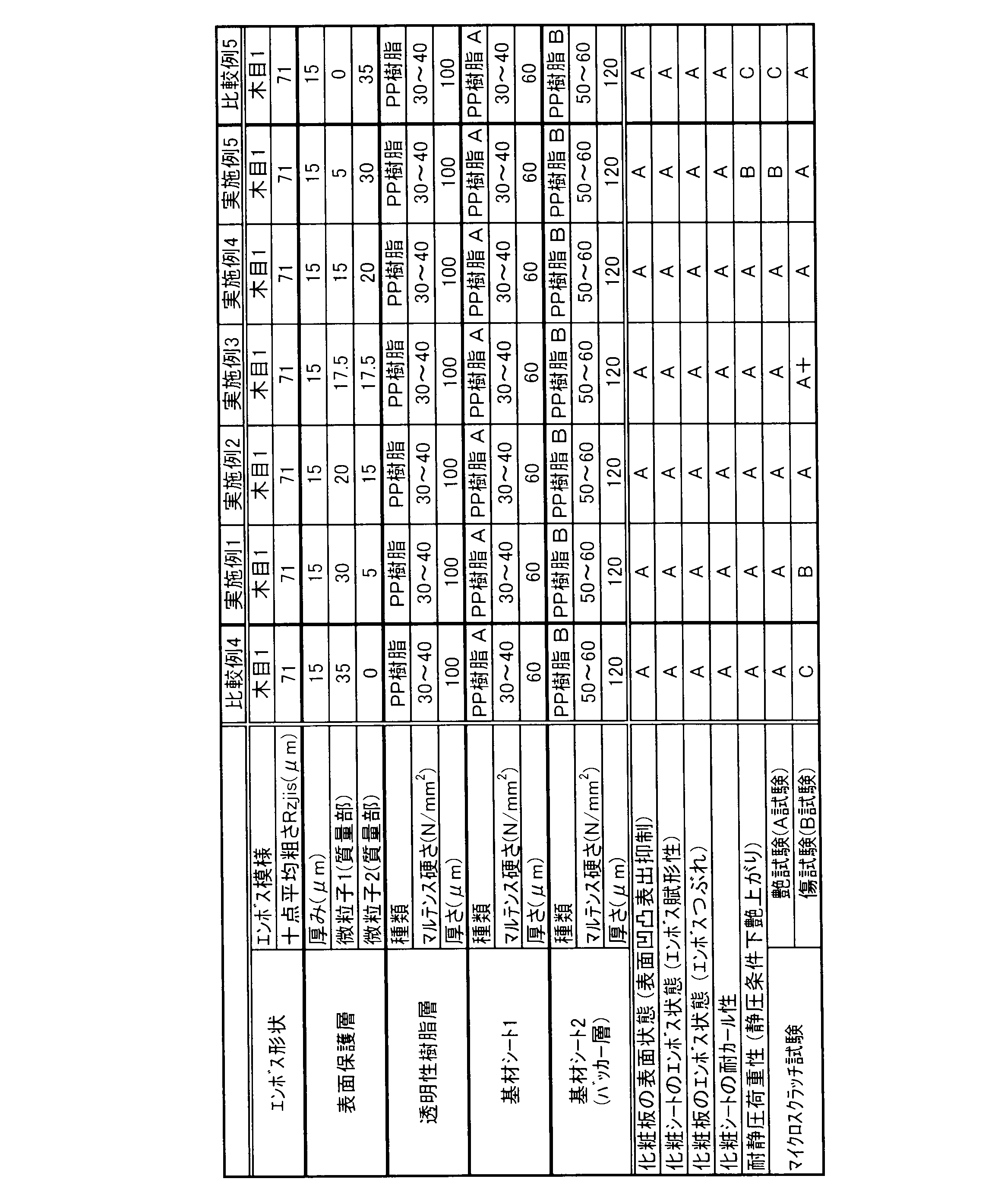

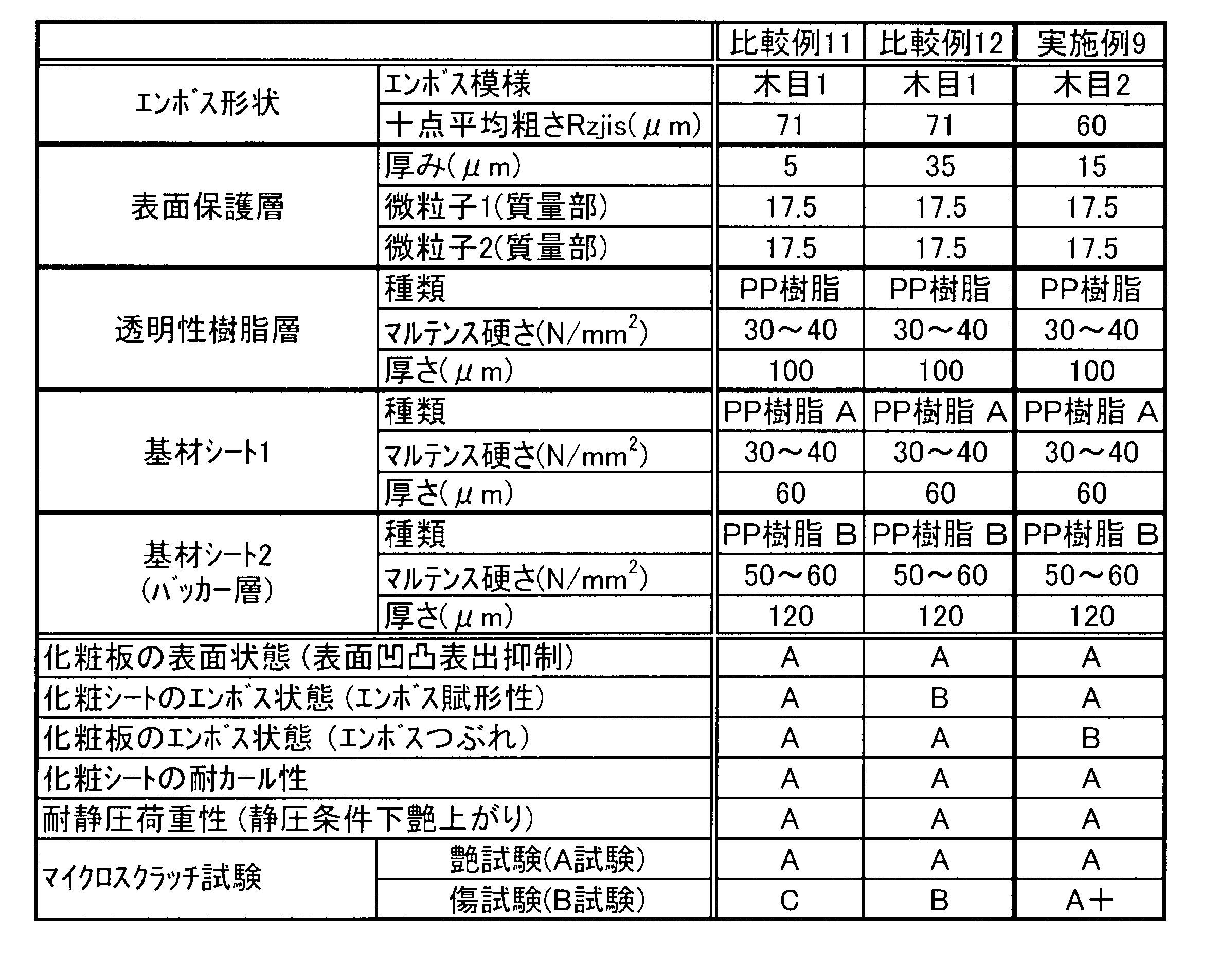


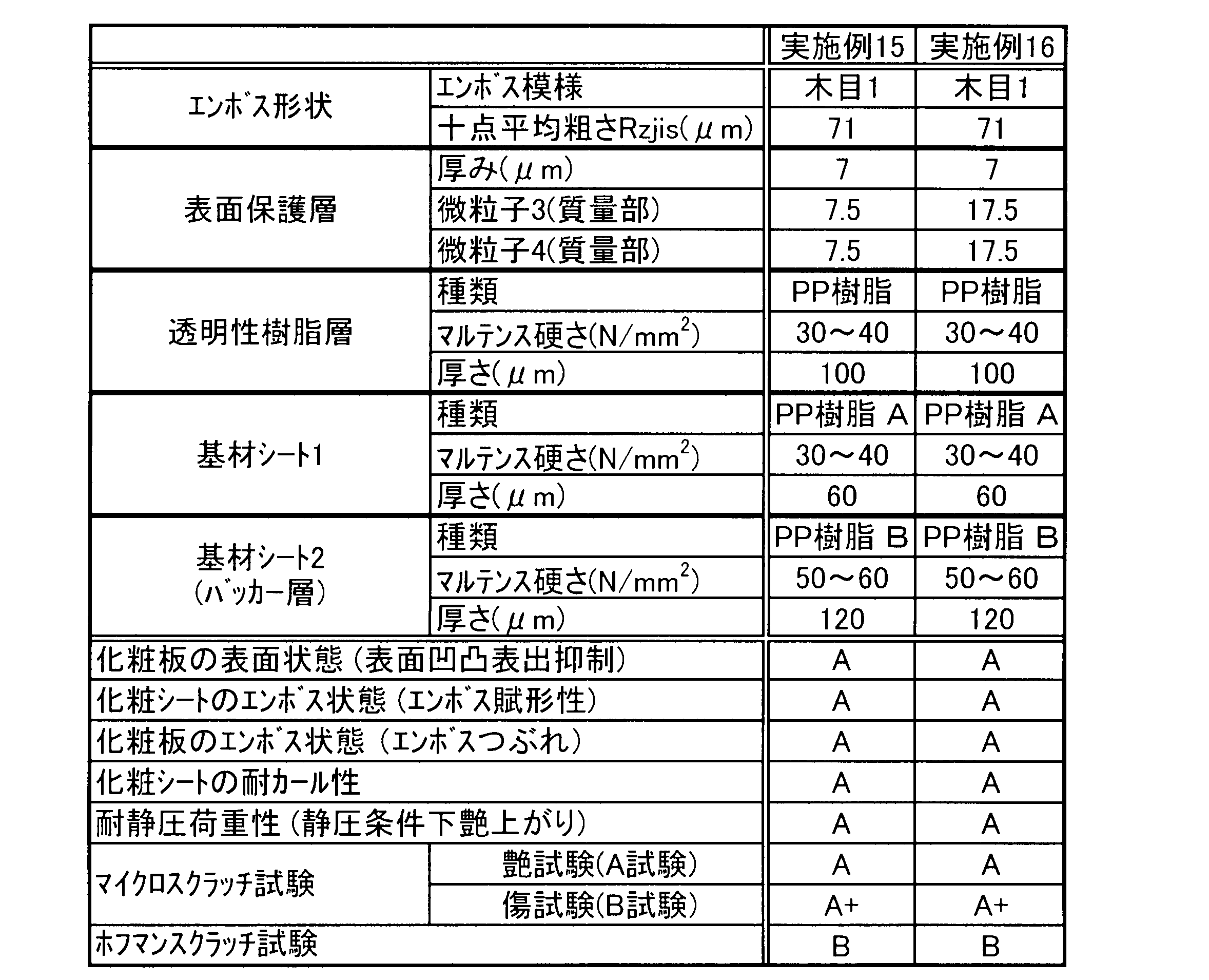
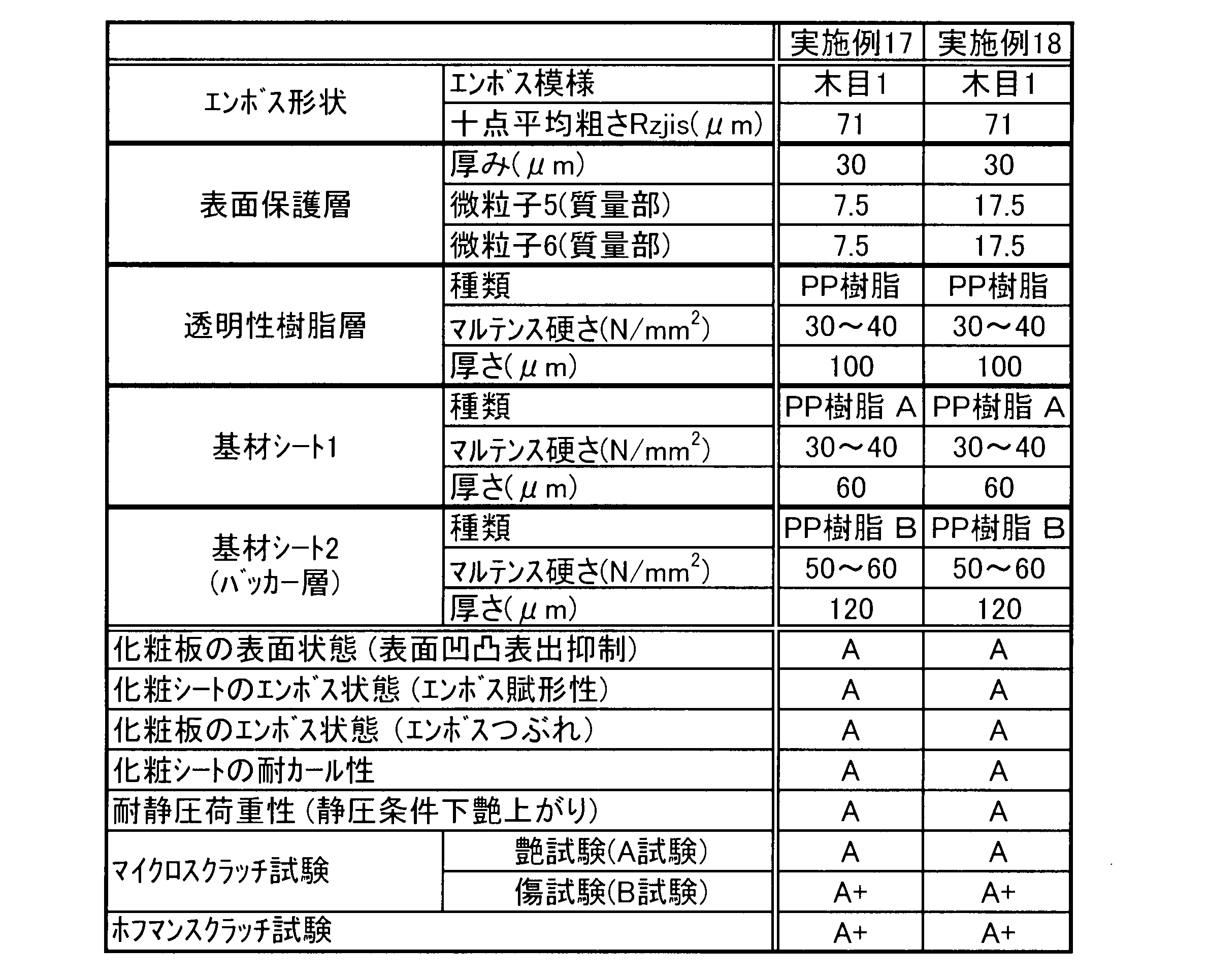
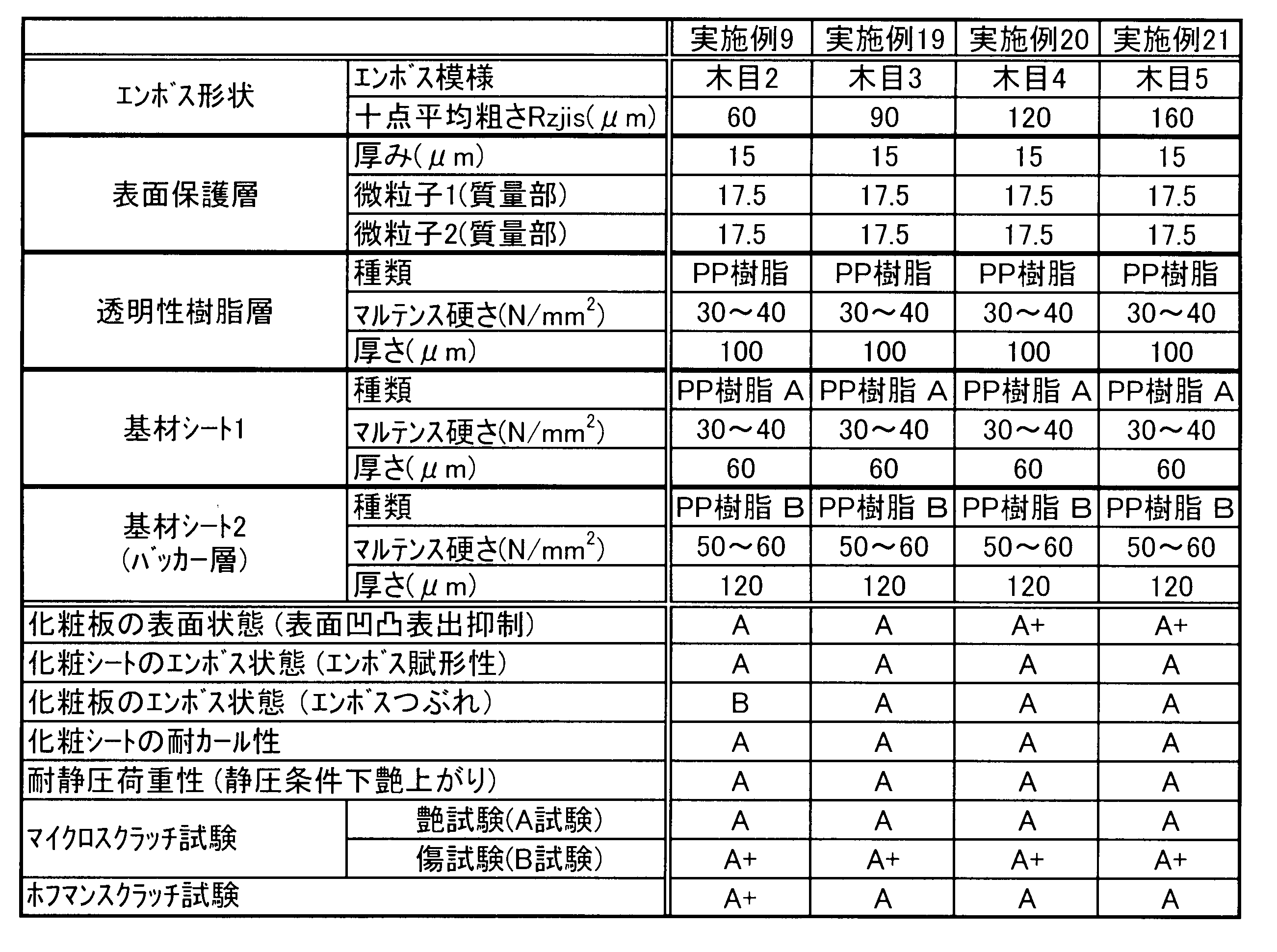

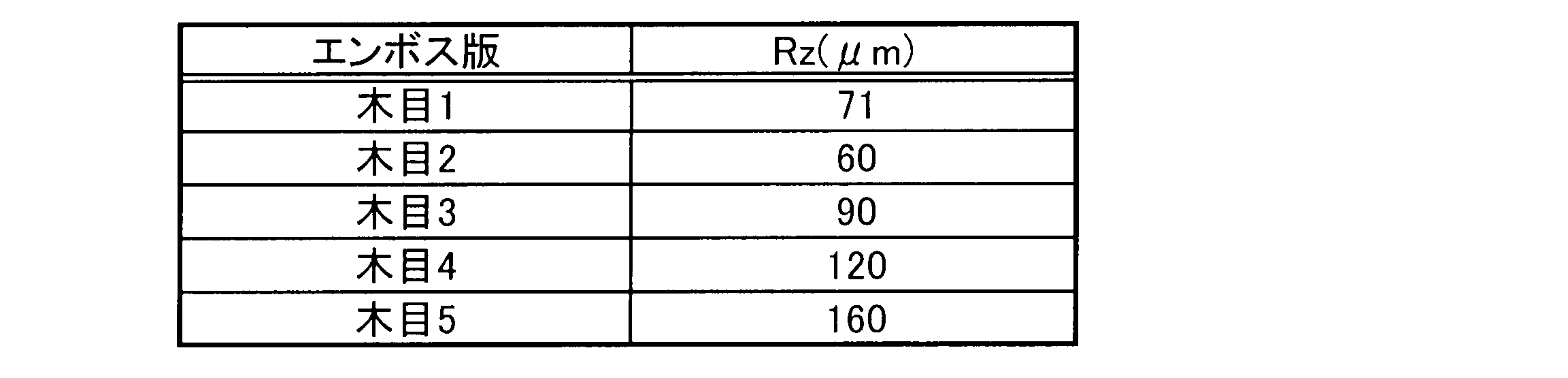
実施例22
60μm厚さの着色ポリプロピレン(PP)フィルムからなる基材シート(アートプライ、三菱樹脂株式会社製)のおもて面に、厚さ2μmの絵柄模様層を印刷により形成した。絵柄模様層上にウレタン系樹脂(セイカボンドE-263/C-75N、大日精化工業株式会社製)からなる2μm厚さの透明性の接着剤層を形成した。接着剤層上に、厚さ100μmの透明ポリプロピレン(PP)系樹脂のシート(ノバテックPP、日本ポリプロ株式会社製)を押出しラミネート方式で積層し、透明性樹脂層を形成した。
・2官能ウレタンアクリレート(Tg=25(℃)、分子量1500)80質量部
・6官能ウレタンアクリレート(Tg=200(℃)以上、分子量1500)20質量
さらに、表面保護層側を赤外線非接触方式のヒーターで加熱することにより基材シート及び透明性樹脂層を柔らかくした後、直ちにエンボス加工を施す(具体的には、後述する木目模様が付されたエンボス版で熱圧する)ことで、エンボス模様(木目模様(木目6))を形成した。
化粧シート表面の十点平均粗さ(前記エンボス模様によるエンボス形状の十点平均粗さ)Rzjisは71μmであり、バッカー層の厚みは120μmであり、バッカー層のマルテンス硬さは50~60N/mm2であった。なお、前記Rzjisを測定する際の測定距離は2cmとした。また、前記マルテンス硬さは、バッカー層の断面方向で測定した。また、表面保護層の艶値(入射角60°)を、日本電色工業株式会社製PG-3Dを使用して測定したところ、前記艶値(GP)は13であった。
まず、基材シート、絵柄模様層、接着剤層、透明性樹脂層及びプライマー層を形成した。前記各層は、それぞれ、実施例22と同様の方法により形成した。
まず、基材シート、絵柄模様層、接着剤層、透明性樹脂層及びプライマー層を形成した。前記各層は、それぞれ、実施例22と同様の方法により形成した。
(1)バッカー層を構成する樹脂成分、及び/又は、(2)バッカー層の厚みを表13及び14に示すように適宜変更した。また、(3)エンボス形状のエンボス模様を表13及び14に示すように、表15に示す木目6~10に適宜変更した。更に、(4)バッカー層のマルテンス硬さを表13及び14に示すように適宜変更した。それ以外は実施例22と同様にして、実施例25~34の化粧シートを調製した。なお、(1)バッカー層を構成する樹脂成分を変更することで、バッカー層のマルテンス硬さを変更することができる。表12~14中、樹脂A、C及びDはホモポリプロピレンであり、樹脂Bはポリエチレンテレフタレート(PET)である。
(1)バッカー層を構成する樹脂成分、及び/又は、(2)バッカー層の厚みを適宜変更する以外は、実施例22と同様にして、比較例17~20の化粧シートを得た。なお、(1)バッカー層を構成する樹脂成分を変更することで、バッカー層のマルテンス硬さを変更することができる。
コルクボード上に水性エマルジョン接着剤(中央理化工業株式会社製リカボンドBA-10L (主剤):BA-11B (硬化剤))を6~7g/尺角塗布し、化粧シートをラミネートして、室温で3日間養生することにより化粧板を作製した。化粧板の表面状態を目視により観察し、以下の評価基準に従って評価した。なお、下記評価基準において、A以上の評価であれば実際の使用状況において問題がない表面状態である。
A:被着材の凹凸形状が表出していない。
B:被着材の凹凸形状が若干表出している。
C:被着材の凹凸形状が明らかに表出している。
化粧シートのエンボス模様の状態を目視により観察し、以下の評価基準に従って評価した。なお、下記評価基準において、A以上の評価であれば実際の使用状況において問題がないエンボス状態である。
A:エンボス模様が明確に残っている。
B:エンボス模様が若干消失している。
C:エンボス模様が殆ど消失している。
化粧板のエンボス状態、すなわち、化粧シートを被着材にラミネートした後のエンボスつぶれを評価した。具体的には、パーティクルボード上に水性エマルジョン接着剤(中央理化工業株式会社製リカボンドBA-10L (主剤):BA-11B (硬化剤))を6~7g/尺角塗布し、化粧シートをラミネートして、室温で3日間養生することにより化粧板を作製した。化粧板のエンボス状態を目視により観察し、以下の評価基準に従って評価した。なお、下記評価基準において、B以上の評価であれば実際の使用状況において問題がないエンボス状態である。
A:エンボス模様がつぶれていない。
B:エンボス模様が若干つぶれている。
C:エンボス模様が殆どつぶれている。
化粧シートを直径3インチ(=76.2mm)の紙管に巻き付け、室温で1週間放置した。化粧シートを巻き出し、カールの状態を目視により観察し、以下の評価基準に従って評価した。なお、下記評価基準において、A以上の評価であれば実際の使用状況において問題がない耐カール性を備えている。
A:化粧シートのカールが殆ど生じていない。
B:化粧シートが若干カールしている。
C:化粧シートが明らかにカールしている。
直径3インチ(=76.2mm)の紙管に、幅が3尺(=909.09mm)のシートを100m分巻き付けることにより、ロール状の化粧シートを得た。当該ロール状の化粧シートを目視で観察し、以下の評価基準に従って評価した。なお、下記評価基準において、B以上の評価であれば、実際の使用状況において問題がない。
A:ロール形状が歪んでいない円形であって、化粧シート表面に割れがない。
B:ロール形状が若干歪んだ円形であって、化粧シート表面に割れがない。
C:(1)ロール形状が歪んだ円形であるか、(2)ロール形状が歪んでいない円形であっても化粧シート表面に割れがあるか、または(3)そもそも化粧シートをロール状にすることができない。
コルクボードよりも表面粗さの粗い被着材(表面粗さRzが通常の被着材の2倍以上である被着材)を用意した。次に、前記被着材の上に水性エマルジョン接着剤(中央理化工業株式会社製リカボンドBA-10L (主剤):BA-11B (硬化剤))を6~7g/尺角塗布した後、実施例22~24の各化粧シートをラミネートし、さらに室温で3日間養生することにより各化粧板を作製した。各化粧板の表面状態を目視により観察し、以下の評価基準に従って評価した。なお、下記評価基準において、B以上の評価であれば実際の使用状況において問題がない表面状態である。
A+:被着材の凹凸形状が表出していない。
A :被着材の凹凸形状が僅かに表出している。
B :被着材の凹凸形状が若干表出している。
C :被着材の凹凸形状が前記B評価の場合よりも表出している。
まず、上述の評価方法6に記載の方法と同様の方法により、各化粧板を作製した。次いで、成人男女20人が前記各化粧板の外観を観察し、木の質感が表現できているか否かを、以下の評価基準で評価した。なお、下記評価基準において、B以上の評価であれば実際の使用状況において問題がない表面状態である。
A+:木の質感が表現できていると判断した成人男女が9割以上。
A :木の質感が表現できていると判断した成人男女が7割以上。
B :木の質感が表現できていると判断した成人男女が5割以上。
C :木の質感が表現できていると判断した成人男女が5割未満。
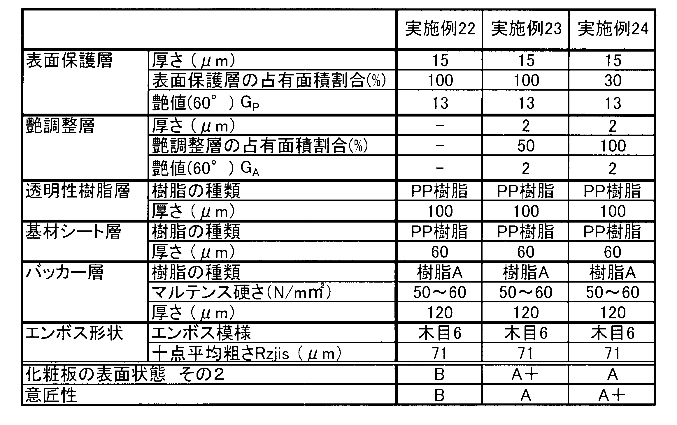


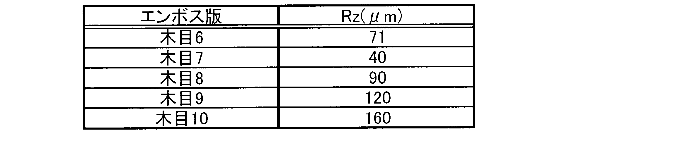
2.基材シート
3.絵柄模様層
4.透明性樹脂層
5.表面保護層
6.微粒子A
7.微粒子B
8.艶調整層
9.バッカー層
Claims (17)
- 基材シート上に、少なくとも透明性樹脂層及び表面保護層がこの順に積層された化粧シートであって、前記基材シート及び前記透明性樹脂層は、非ハロゲン系熱可塑性樹脂を含有する、ことを特徴とする化粧シート。
- 基材シート上に、少なくとも絵柄模様層、透明性樹脂層及び表面保護層がこの順に積層された、請求項1に記載の化粧シートであって、
(1)前記表面保護層は、厚みが7~30μmであり、且つ前記表面保護層の厚み以下の粒子径の微粒子A、及び前記表面保護層の厚みより大きい粒子径の微粒子Bを含有し、
(2)前記微粒子Aの含有量及び前記微粒子Bの含有量は、前記表面保護層の樹脂成分100質量部に対して、それぞれ5~30質量部であり、且つ前記微粒子Aの含有量及び前記微粒子Bの含有量の合計は、前記表面保護層の樹脂成分100質量部に対して15~35質量部であり、
(3)前記基材シート及び前記透明性樹脂層は、非ハロゲン系熱可塑性樹脂を含有し、
(4)前記基材シートは、厚みが180~350μmであり、且つマルテンス硬さが50N/mm2以上の領域が、前記基材シートの前記絵柄模様層側の面とは反対側の面から120μm以上の厚みで存在し、
(5)前記表面保護層側からエンボス加工されている、
ことを特徴とする化粧シート。 - 前記化粧シートの表面の十点平均粗さRzjisが60μm以上である、請求項2に記載の化粧シート。
- 前記化粧シートの表面の60°グロスが14以下である、請求項2又は3に記載の化粧シート。
- 前記微粒子A及び前記微粒子Bがシリカ微粒子である、請求項2~4のいずれかに記載の化粧シート。
- 前記透明性樹脂層上に艶調整層が形成されており、且つ、前記艶調整層は、前記表面保護層と隣接して形成されている、請求項2~5のいずれかに記載の化粧シート。
- 前記非ハロゲン系熱可塑性樹脂は、オレフィン系熱可塑性樹脂である、請求項2~6のいずれかに記載の化粧シート。
- 前記表面保護層は電離放射線硬化型樹脂層を含む、請求項2~7のいずれかに記載の化粧シート。
- 請求項2~8のいずれかに記載の化粧シートを被着材に貼着してなる化粧板。
- 前記被着材が、チップボード、又はチップボードが積層された複合基材である、請求項9に記載の化粧板。
- 基材シート上に少なくとも透明性樹脂層及び表面保護層が順に積層されており、且つ、前記基材シートの裏面に少なくともバッカー層が積層されている、請求項1に記載の化粧シートであって、
(1)前記化粧シートの表面の十点平均粗さRzjisが40μm以上であり、
(2)前記表面保護層が電離放射線硬化型樹脂を含み、
(3)前記基材シート、前記透明性樹脂層及び前記バッカー層が、いずれも非ハロゲン系熱可塑性樹脂を含み、
(4)前記バッカー層の厚みが120~250μmであり、
(5)前記バッカー層のマルテンス硬さが50~80N/mm2であり、
(6)前記バッカー層は、前記基材シートの裏面に対してバッカー層形成用樹脂組成物を溶融状態で押出し成形することにより積層される、
ことを特徴とする化粧シート。 - 前記透明性樹脂層上に艶調整層が形成されており、且つ、前記艶調整層は、前記表面保護層と隣接して形成されている、請求項11に記載の化粧シート。
- 請求項11又は12に記載の化粧シートをロール状に巻くことにより得られる、ロール状物。
- 被着材上に、請求項11若しくは12に記載の化粧シート、又は請求項13に記載のロール状物を巻き出して得られる化粧シートが積層された、化粧板。
- 基材シート上に少なくとも透明性樹脂層及び表面保護層が順に積層されており、且つ、前記基材シートの裏面に少なくともバッカー層が積層されている化粧シートの製造方法であって、以下の工程1~3:
(i) 基材シート上に、少なくとも透明性樹脂層及び表面保護層を順に有する積層シートであって、
前記表面保護層が電離放射線硬化型樹脂を含み、
前記基材シート及び前記透明性樹脂層が、いずれも非ハロゲン熱可塑性樹脂を含む、積層シートを得る工程1、
(ii) 前記積層シートの前記表面保護層の上からエンボス加工を施すことにより、前記積層シートの表面の十点平均粗さRzjisを40μm以上にする工程2、並びに、
(iii) 前記基材シートの裏面に対してバッカー層形成用樹脂組成物を溶融状態で押出し成形することにより、
前記バッカー層が非ハロゲン系熱可塑性樹脂を含み、
前記バッカー層の厚みが120~250μmであり、
前記バッカー層のマルテンス硬さが50~80N/mm2である、
バッカー層を積層する工程3、
を順に含むことを特徴とする化粧シートの製造方法。 - 基材シート上に少なくとも透明性樹脂層及び表面保護層が順に積層されており、且つ、前記基材シートの裏面に少なくともバッカー層が積層されている化粧シートの製造方法であって、以下の工程1~4:
(i) 基材シート上に、少なくとも透明性樹脂層を有する積層体であって、
前記基材シート及び前記透明性樹脂層が、いずれも非ハロゲン熱可塑性樹脂を含む、積層体を得る工程1、
(ii) 前記積層体の前記透明性樹脂層の上からエンボス加工を施す工程2、
(iii) 前記透明性樹脂層上に、電離放射線硬化型樹脂を含む表面保護層形成用樹脂組成物を塗工することにより、
基材シート上に、少なくとも透明性樹脂層及び表面保護層を有する積層シートであって、
前記積層シートの表面の十点平均粗さRzjisが40μm以上である積層シートを得る工程3、並びに、
(iv) 前記基材シートの裏面に対してバッカー層形成用樹脂組成物を溶融状態で押出し成形することにより、
前記バッカー層が非ハロゲン系熱可塑性樹脂を含み、
前記バッカー層の厚みが120~250μmであり、
前記バッカー層のマルテンス硬さが50~80N/mm2である、
バッカー層を積層する工程4、
を順に含むことを特徴とする化粧シートの製造方法。 - 請求項15又は16に記載の化粧シートの製造方法により得られた化粧シートの表面保護層が最表面層となるように、前記化粧シートを被着材上に積層する化粧板の製造方法。
Priority Applications (5)
| Application Number | Priority Date | Filing Date | Title |
|---|---|---|---|
| KR1020187022395A KR102014667B1 (ko) | 2014-01-10 | 2015-01-09 | 화장 시트 및 화장판, 그리고 그것들의 제조 방법 |
| EP15735031.5A EP3098071B1 (en) | 2014-01-10 | 2015-01-09 | Decorative sheet and decorative plate |
| EP18199139.9A EP3446873B1 (en) | 2014-01-10 | 2015-01-09 | Decorative sheet and decorative plate, and processes for producing same |
| CN201580004218.7A CN105899362B (zh) | 2014-01-10 | 2015-01-09 | 装饰片和装饰板、以及它们的制造方法 |
| KR1020167021683A KR101906024B1 (ko) | 2014-01-10 | 2015-01-09 | 화장 시트 및 화장판, 그리고 그것들의 제조 방법 |
Applications Claiming Priority (8)
| Application Number | Priority Date | Filing Date | Title |
|---|---|---|---|
| JP2014-003649 | 2014-01-10 | ||
| JP2014003649 | 2014-01-10 | ||
| JP2014-003666 | 2014-01-10 | ||
| JP2014003666 | 2014-01-10 | ||
| JP2014195342 | 2014-09-25 | ||
| JP2014195353 | 2014-09-25 | ||
| JP2014-195342 | 2014-09-25 | ||
| JP2014-195353 | 2014-09-25 |
Publications (1)
| Publication Number | Publication Date |
|---|---|
| WO2015105168A1 true WO2015105168A1 (ja) | 2015-07-16 |
Family
ID=53523992
Family Applications (1)
| Application Number | Title | Priority Date | Filing Date |
|---|---|---|---|
| PCT/JP2015/050447 WO2015105168A1 (ja) | 2014-01-10 | 2015-01-09 | 化粧シート及び化粧板、並びに、それらの製造方法 |
Country Status (5)
| Country | Link |
|---|---|
| EP (2) | EP3446873B1 (ja) |
| KR (2) | KR102014667B1 (ja) |
| CN (2) | CN105899362B (ja) |
| PT (2) | PT3446873T (ja) |
| WO (1) | WO2015105168A1 (ja) |
Cited By (6)
| Publication number | Priority date | Publication date | Assignee | Title |
|---|---|---|---|---|
| WO2018062340A1 (ja) * | 2016-09-28 | 2018-04-05 | 大日本印刷株式会社 | 化粧シート及び化粧板 |
| EP3357685A4 (en) * | 2015-09-30 | 2019-06-05 | Dai Nippon Printing Co., Ltd. | COSMETIC SHEET AND COSMETIC PLATE |
| JP2019209499A (ja) * | 2018-05-31 | 2019-12-12 | 凸版印刷株式会社 | 化粧シート |
| EP3674082A1 (en) * | 2018-12-29 | 2020-07-01 | Shanghai Jinka Flooring Technology Co., Ltd. | Anti-slip floortile |
| CN112443120A (zh) * | 2020-12-15 | 2021-03-05 | 安徽森泰木塑科技地板有限公司 | 一种pvc共挤发泡地板及其制备方法 |
| EP3950327A4 (en) * | 2019-03-25 | 2022-12-14 | Dai Nippon Printing Co., Ltd. | DECORATIVE SHEET AND DECORATIVE LAMINATE |
Families Citing this family (15)
| Publication number | Priority date | Publication date | Assignee | Title |
|---|---|---|---|---|
| CN105090193A (zh) * | 2015-08-12 | 2015-11-25 | 天津航天液压装备有限公司 | 木质件表面橡胶软化工艺 |
| JP2018079603A (ja) * | 2016-11-15 | 2018-05-24 | 凸版印刷株式会社 | 化粧シート及び化粧板 |
| US20200223193A1 (en) * | 2017-09-29 | 2020-07-16 | Dai Nippon Printing Co., Ltd. | Cosmetic sheet and cosmetic plate |
| JP6981269B2 (ja) * | 2018-01-17 | 2021-12-15 | 凸版印刷株式会社 | 化粧シート、化粧材、化粧シートの製造方法 |
| JP2019150976A (ja) * | 2018-03-01 | 2019-09-12 | パナソニックIpマネジメント株式会社 | 加飾金属部品の加工方法と加飾金属部品 |
| US20220009207A1 (en) * | 2018-10-12 | 2022-01-13 | Dai Nippon Printing Co., Ltd. | Decorative board, transparent resin film, and decorative board production method |
| KR102307647B1 (ko) * | 2018-12-19 | 2021-10-05 | 주식회사 포스코 | 석재무늬 도장층을 구비하는 건축용 마감재 및 그 제조방법 |
| JP7316583B2 (ja) * | 2019-03-06 | 2023-07-28 | パナソニックIpマネジメント株式会社 | 加飾シート及びその製造方法、表示装置 |
| US20220184932A1 (en) * | 2019-03-25 | 2022-06-16 | Dai Nippon Printing Co., Ltd. | Decorative sheet and decorative plate |
| WO2020213342A1 (ja) * | 2019-04-18 | 2020-10-22 | 大日本印刷株式会社 | 透明性樹脂フィルム、透明性樹脂フィルムの製造方法、及び、化粧材 |
| JP2020179517A (ja) * | 2019-04-23 | 2020-11-05 | 凸版印刷株式会社 | 加飾シート |
| JP6996664B2 (ja) * | 2019-09-30 | 2022-01-17 | 大日本印刷株式会社 | 化粧材の製造方法 |
| WO2021205842A1 (ja) * | 2020-04-09 | 2021-10-14 | 大日本印刷株式会社 | 透明性樹脂フィルム、透明性樹脂フィルムの製造方法、化粧板、及び、化粧板の製造方法 |
| WO2022097052A1 (en) * | 2020-11-06 | 2022-05-12 | Flooring Industries Limited, Sarl | Decorative panel comprising grout imitation |
| CN114192369B (zh) * | 2021-09-27 | 2023-01-20 | 中山易必固电子束科技有限公司 | 一种带立体纹路的彩色超级哑光装饰板的制备方法 |
Citations (6)
| Publication number | Priority date | Publication date | Assignee | Title |
|---|---|---|---|---|
| JPH0545180B2 (ja) | 1987-02-18 | 1993-07-08 | Hitachi Ltd | |
| JP2003013587A (ja) | 2001-06-28 | 2003-01-15 | Toppan Printing Co Ltd | 床用シート及び床材 |
| JP2007291836A (ja) * | 2006-03-31 | 2007-11-08 | Dainippon Printing Co Ltd | 床材用化粧材 |
| JP2012210741A (ja) * | 2011-03-30 | 2012-11-01 | Dainippon Printing Co Ltd | 真空成形用化粧シート、及び該化粧シートを用いてなる化粧材 |
| JP2012215064A (ja) * | 2011-03-31 | 2012-11-08 | Dainippon Printing Co Ltd | 床用化粧シート及び床用化粧材 |
| JP2013067038A (ja) * | 2011-09-21 | 2013-04-18 | Dainippon Printing Co Ltd | 床用化粧シート及びその製造方法 |
Family Cites Families (7)
| Publication number | Priority date | Publication date | Assignee | Title |
|---|---|---|---|---|
| JPS5045180A (ja) | 1973-08-28 | 1975-04-23 | ||
| JP2003011277A (ja) * | 2001-06-29 | 2003-01-15 | Toppan Printing Co Ltd | 化粧材 |
| JP4839541B2 (ja) * | 2001-07-25 | 2011-12-21 | 凸版印刷株式会社 | 床用化粧シート |
| JP4659752B2 (ja) * | 2004-09-30 | 2011-03-30 | 大日本印刷株式会社 | 化粧材 |
| JP5045180B2 (ja) | 2006-03-30 | 2012-10-10 | 大日本印刷株式会社 | 床材用化粧シートの製造方法 |
| JP5999876B2 (ja) * | 2011-03-31 | 2016-09-28 | 大日本印刷株式会社 | 化粧シート及び化粧板 |
| JP5909963B2 (ja) * | 2011-09-27 | 2016-04-27 | 大日本印刷株式会社 | 床用化粧材 |
-
2015
- 2015-01-09 KR KR1020187022395A patent/KR102014667B1/ko active IP Right Grant
- 2015-01-09 WO PCT/JP2015/050447 patent/WO2015105168A1/ja active Application Filing
- 2015-01-09 CN CN201580004218.7A patent/CN105899362B/zh active Active
- 2015-01-09 PT PT181991399T patent/PT3446873T/pt unknown
- 2015-01-09 CN CN201810159170.2A patent/CN108284654B/zh active Active
- 2015-01-09 EP EP18199139.9A patent/EP3446873B1/en active Active
- 2015-01-09 EP EP15735031.5A patent/EP3098071B1/en active Active
- 2015-01-09 KR KR1020167021683A patent/KR101906024B1/ko active IP Right Grant
- 2015-01-09 PT PT15735031T patent/PT3098071T/pt unknown
Patent Citations (6)
| Publication number | Priority date | Publication date | Assignee | Title |
|---|---|---|---|---|
| JPH0545180B2 (ja) | 1987-02-18 | 1993-07-08 | Hitachi Ltd | |
| JP2003013587A (ja) | 2001-06-28 | 2003-01-15 | Toppan Printing Co Ltd | 床用シート及び床材 |
| JP2007291836A (ja) * | 2006-03-31 | 2007-11-08 | Dainippon Printing Co Ltd | 床材用化粧材 |
| JP2012210741A (ja) * | 2011-03-30 | 2012-11-01 | Dainippon Printing Co Ltd | 真空成形用化粧シート、及び該化粧シートを用いてなる化粧材 |
| JP2012215064A (ja) * | 2011-03-31 | 2012-11-08 | Dainippon Printing Co Ltd | 床用化粧シート及び床用化粧材 |
| JP2013067038A (ja) * | 2011-09-21 | 2013-04-18 | Dainippon Printing Co Ltd | 床用化粧シート及びその製造方法 |
Cited By (15)
| Publication number | Priority date | Publication date | Assignee | Title |
|---|---|---|---|---|
| US11318703B2 (en) | 2015-09-30 | 2022-05-03 | Dai Nippon Printing Co., Ltd. | Cosmetic sheet and cosmetic plate |
| EP3357685A4 (en) * | 2015-09-30 | 2019-06-05 | Dai Nippon Printing Co., Ltd. | COSMETIC SHEET AND COSMETIC PLATE |
| US11207862B2 (en) | 2016-09-28 | 2021-12-28 | Dai Nippon Printing Co., Ltd. | Decorative sheet and decorative plate |
| US20190248100A1 (en) * | 2016-09-28 | 2019-08-15 | Dai Nippon Printing Co., Ltd. | Decorative sheet and decorative plate |
| EP3521018A4 (en) * | 2016-09-28 | 2020-04-22 | Dai Nippon Printing Co., Ltd. | ORNAMENTAL FILM AND PLATE |
| WO2018062340A1 (ja) * | 2016-09-28 | 2018-04-05 | 大日本印刷株式会社 | 化粧シート及び化粧板 |
| JPWO2018062340A1 (ja) * | 2016-09-28 | 2019-07-11 | 大日本印刷株式会社 | 化粧シート及び化粧板 |
| JP7103224B2 (ja) | 2016-09-28 | 2022-07-20 | 大日本印刷株式会社 | 化粧シート及び化粧板 |
| JP2019209499A (ja) * | 2018-05-31 | 2019-12-12 | 凸版印刷株式会社 | 化粧シート |
| JP7187823B2 (ja) | 2018-05-31 | 2022-12-13 | 凸版印刷株式会社 | 化粧シート |
| EP3674082A1 (en) * | 2018-12-29 | 2020-07-01 | Shanghai Jinka Flooring Technology Co., Ltd. | Anti-slip floortile |
| US11549271B2 (en) | 2018-12-29 | 2023-01-10 | Shanghai Jinka Flooring Technology Co., Ltd. | Anti-slip floortile |
| EP3950327A4 (en) * | 2019-03-25 | 2022-12-14 | Dai Nippon Printing Co., Ltd. | DECORATIVE SHEET AND DECORATIVE LAMINATE |
| CN112443120A (zh) * | 2020-12-15 | 2021-03-05 | 安徽森泰木塑科技地板有限公司 | 一种pvc共挤发泡地板及其制备方法 |
| CN112443120B (zh) * | 2020-12-15 | 2021-10-29 | 安徽森泰木塑科技地板有限公司 | 一种pvc共挤发泡地板及其制备方法 |
Also Published As
| Publication number | Publication date |
|---|---|
| PT3446873T (pt) | 2021-08-10 |
| EP3098071A4 (en) | 2018-04-11 |
| CN105899362B (zh) | 2018-06-19 |
| PT3098071T (pt) | 2019-06-27 |
| EP3446873B1 (en) | 2021-07-07 |
| KR102014667B1 (ko) | 2019-08-26 |
| CN105899362A (zh) | 2016-08-24 |
| EP3446873A1 (en) | 2019-02-27 |
| KR20180091112A (ko) | 2018-08-14 |
| EP3098071B1 (en) | 2019-05-22 |
| EP3098071A1 (en) | 2016-11-30 |
| CN108284654A (zh) | 2018-07-17 |
| CN108284654B (zh) | 2020-08-07 |
| KR20160107252A (ko) | 2016-09-13 |
| KR101906024B1 (ko) | 2018-10-08 |
Similar Documents
| Publication | Publication Date | Title |
|---|---|---|
| WO2015105168A1 (ja) | 化粧シート及び化粧板、並びに、それらの製造方法 | |
| JP6520128B2 (ja) | 化粧シート及び化粧板 | |
| US11207862B2 (en) | Decorative sheet and decorative plate | |
| JP4658749B2 (ja) | 耐衝撃性及び耐スクラッチ性に優れた床材用化粧シート | |
| JP6791232B2 (ja) | 化粧シート及びそれを用いた化粧板 | |
| JP5045180B2 (ja) | 床材用化粧シートの製造方法 | |
| JP5429129B2 (ja) | 耐衝撃性及び耐スクラッチ性に優れた床材用化粧シート | |
| JP2017019274A (ja) | 化粧シート、化粧板及び化粧板の製造方法 | |
| JP5151107B2 (ja) | 化粧シート | |
| JP5700100B2 (ja) | 床材用化粧シート及び床用化粧材 | |
| JP5533937B2 (ja) | 化粧シート | |
| JP6307792B2 (ja) | 化粧シート及びその製造方法 | |
| JP6520129B2 (ja) | 化粧シート及びその製造方法、並びに、化粧板及びその製造方法 | |
| KR101456731B1 (ko) | 화장 시트 및 그것을 사용한 화장판 | |
| JP2008155460A (ja) | 化粧シートおよびそれを用いた化粧板 | |
| JP6171459B2 (ja) | 化粧シート |
Legal Events
| Date | Code | Title | Description |
|---|---|---|---|
| 121 | Ep: the epo has been informed by wipo that ep was designated in this application |
Ref document number: 15735031 Country of ref document: EP Kind code of ref document: A1 |
|
| DPE1 | Request for preliminary examination filed after expiration of 19th month from priority date (pct application filed from 20040101) | ||
| NENP | Non-entry into the national phase |
Ref country code: DE |
|
| REEP | Request for entry into the european phase |
Ref document number: 2015735031 Country of ref document: EP |
|
| WWE | Wipo information: entry into national phase |
Ref document number: 2015735031 Country of ref document: EP |
|
| ENP | Entry into the national phase |
Ref document number: 20167021683 Country of ref document: KR Kind code of ref document: A |