WO2015105093A1 - 電動機の制御装置 - Google Patents
電動機の制御装置 Download PDFInfo
- Publication number
- WO2015105093A1 WO2015105093A1 PCT/JP2015/050120 JP2015050120W WO2015105093A1 WO 2015105093 A1 WO2015105093 A1 WO 2015105093A1 JP 2015050120 W JP2015050120 W JP 2015050120W WO 2015105093 A1 WO2015105093 A1 WO 2015105093A1
- Authority
- WO
- WIPO (PCT)
- Prior art keywords
- range
- voltage
- error
- δγc
- voltage command
- Prior art date
Links
- 230000004907 flux Effects 0.000 claims abstract description 56
- 238000004364 calculation method Methods 0.000 claims abstract description 45
- 230000001360 synchronised effect Effects 0.000 claims description 19
- 238000004519 manufacturing process Methods 0.000 claims description 10
- 230000005856 abnormality Effects 0.000 claims description 8
- 238000000034 method Methods 0.000 description 16
- 238000010586 diagram Methods 0.000 description 11
- 238000006243 chemical reaction Methods 0.000 description 9
- 238000004804 winding Methods 0.000 description 9
- 230000006870 function Effects 0.000 description 5
- 239000011159 matrix material Substances 0.000 description 4
- 230000004048 modification Effects 0.000 description 4
- 238000012986 modification Methods 0.000 description 4
- 230000008901 benefit Effects 0.000 description 2
- 230000002093 peripheral effect Effects 0.000 description 2
- 238000001514 detection method Methods 0.000 description 1
- 238000005516 engineering process Methods 0.000 description 1
- 230000001771 impaired effect Effects 0.000 description 1
- 230000008569 process Effects 0.000 description 1
- 230000002123 temporal effect Effects 0.000 description 1
- 230000017105 transposition Effects 0.000 description 1
Images


Classifications
-
- H—ELECTRICITY
- H02—GENERATION; CONVERSION OR DISTRIBUTION OF ELECTRIC POWER
- H02P—CONTROL OR REGULATION OF ELECTRIC MOTORS, ELECTRIC GENERATORS OR DYNAMO-ELECTRIC CONVERTERS; CONTROLLING TRANSFORMERS, REACTORS OR CHOKE COILS
- H02P6/00—Arrangements for controlling synchronous motors or other dynamo-electric motors using electronic commutation dependent on the rotor position; Electronic commutators therefor
- H02P6/12—Monitoring commutation; Providing indication of commutation failure
-
- H—ELECTRICITY
- H02—GENERATION; CONVERSION OR DISTRIBUTION OF ELECTRIC POWER
- H02P—CONTROL OR REGULATION OF ELECTRIC MOTORS, ELECTRIC GENERATORS OR DYNAMO-ELECTRIC CONVERTERS; CONTROLLING TRANSFORMERS, REACTORS OR CHOKE COILS
- H02P21/00—Arrangements or methods for the control of electric machines by vector control, e.g. by control of field orientation
- H02P21/14—Estimation or adaptation of machine parameters, e.g. flux, current or voltage
- H02P21/18—Estimation of position or speed
-
- H—ELECTRICITY
- H02—GENERATION; CONVERSION OR DISTRIBUTION OF ELECTRIC POWER
- H02P—CONTROL OR REGULATION OF ELECTRIC MOTORS, ELECTRIC GENERATORS OR DYNAMO-ELECTRIC CONVERTERS; CONTROLLING TRANSFORMERS, REACTORS OR CHOKE COILS
- H02P25/00—Arrangements or methods for the control of AC motors characterised by the kind of AC motor or by structural details
- H02P25/02—Arrangements or methods for the control of AC motors characterised by the kind of AC motor or by structural details characterised by the kind of motor
- H02P25/022—Synchronous motors
- H02P25/024—Synchronous motors controlled by supply frequency
-
- H—ELECTRICITY
- H02—GENERATION; CONVERSION OR DISTRIBUTION OF ELECTRIC POWER
- H02P—CONTROL OR REGULATION OF ELECTRIC MOTORS, ELECTRIC GENERATORS OR DYNAMO-ELECTRIC CONVERTERS; CONTROLLING TRANSFORMERS, REACTORS OR CHOKE COILS
- H02P29/00—Arrangements for regulating or controlling electric motors, appropriate for both AC and DC motors
- H02P29/02—Providing protection against overload without automatic interruption of supply
- H02P29/032—Preventing damage to the motor, e.g. setting individual current limits for different drive conditions
-
- H—ELECTRICITY
- H02—GENERATION; CONVERSION OR DISTRIBUTION OF ELECTRIC POWER
- H02P—CONTROL OR REGULATION OF ELECTRIC MOTORS, ELECTRIC GENERATORS OR DYNAMO-ELECTRIC CONVERTERS; CONTROLLING TRANSFORMERS, REACTORS OR CHOKE COILS
- H02P8/00—Arrangements for controlling dynamo-electric motors rotating step by step
- H02P8/36—Protection against faults, e.g. against overheating or step-out; Indicating faults
- H02P8/38—Protection against faults, e.g. against overheating or step-out; Indicating faults the fault being step-out
Definitions
- This invention relates to a technique for controlling an electric motor, and more particularly to a technique for determining that an abnormality has occurred in a synchronous motor.
- Patent documents 1 to 3 are listed as documents illustrating such techniques.
- Patent Document 1 discloses a technique for determining a step-out from a deviation in d-axis current and a q-axis command voltage.
- Patent Document 2 discloses a technique for detecting a step-out by comparing a model voltage with a voltage command.
- Patent Document 3 discloses a technique for determining a step-out if the magnetic flux obtained from the current and the rotational speed command is equal to or less than a threshold value.
- an object of the present application is to provide a technique for determining the presence or absence of an abnormality (for example, step-out) of an electric motor in consideration of variations in specifications.
- the motor control device controls the synchronous motor.
- the control device includes an electric motor driver (2,104) that applies a voltage ([v x * ]) to the electric motor based on a voltage command ([v ⁇ * ]), and a current ([i ⁇ c ] that flows through the electric motor. )) With respect to the command value ([i ⁇ * ]) for the current, or the air gap magnetic flux ([ ⁇ ⁇ c ]) in the motor with respect to the command value ([ ⁇ ⁇ * ]) for the air gap magnetic flux.
- a feedback amount calculation unit (1022) that determines a feedback amount based on a deviation
- a voltage command generation unit (1024) that generates the voltage command based on the feedback amount, the current, and the voltage command based on the voltage command
- a voltage error calculation unit (1025) for calculating a voltage command error ([ ⁇ v ⁇ * ]), and the feedback amount deviates from a range in which the error fluctuates.
- a determination unit (109) that determines that an abnormality has occurred in the electric motor.
- the error ([ ⁇ v ⁇ * ]) includes the current ([i ⁇ c ]), the voltage command ([v ⁇ * ]), the manufacturing tolerance of the synchronous motor (3), and the guaranteed range of the operating temperature.
- the range in which the error ([ ⁇ v ⁇ * ]) varies includes the range in which the error (e iI [I] [i ⁇ c ]) in phase with the current ([i ⁇ c ]) varies, and the current
- the range in which the error ([ ⁇ v ⁇ * ]) fluctuates is the maximum value or the lower limit of the fluctuation range, the maximum value in the combination of the current ([i ⁇ c ]) and the voltage command ([v ⁇ * ]) or Set by / and minimum value.
- the control apparatus further includes a feedforward amount calculation unit (1023) that determines a feedforward amount ([F]) based on a term obtained by excluding the partial term from the voltage equation.
- the voltage command generation unit (1024) further generates the voltage command ([v ⁇ * ]) based on the feedforward amount.
- control device further includes a feedforward amount calculation unit (1023) that determines a feedforward amount ([F]) based on the voltage equation.
- the voltage command generation unit (1024) further generates the voltage command ([v ⁇ * ]) based on the feedforward amount ([F]).
- the motor control device of the present invention it can be determined that an abnormality has occurred in the motor when the feedback amount deviates from the predetermined range.
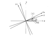
- the vector diagram which shows the relationship between the air gap magnetic flux and field magnetic flux in a synchronous motor.
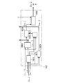
- the block diagram which shows the structure of the motor control apparatus concerning 1st Embodiment, and its peripheral device.
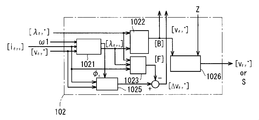
- the block diagram which shows the structure of the voltage command calculation part in 1st Embodiment.
- the block diagram which shows the structure of the voltage command calculation part in 2nd Embodiment.
- the block diagram which shows the structure of the voltage command calculation part in 3rd Embodiment.
- FIG. 1 shows a synchronous motor (hereinafter, simply referred to as “motor”.
- a motor that does not have a field such as a switched reluctance motor.
- the electric motor has a permanent magnet
- the field magnetic flux [ ⁇ 0] is generated by the permanent magnet
- current flows in the field winding. Generated by flowing.
- rotating coordinate system as rotating coordinate system synchronized with motor rotation.
- the d-axis is set in phase with the field magnetic flux [ ⁇ 0], and the q-axis is phase-shifted with respect to the d-axis in a direction (hereinafter simply referred to as “rotation direction”) that is desired to be rotated by the motor control.
- Rotation direction a direction that is desired to be rotated by the motor control. Advance 90 degrees.
- a ⁇ - ⁇ rotating coordinate system and a ⁇ c- ⁇ c rotating coordinate system are introduced as rotating coordinate systems.
- the phase advances at a phase angle ⁇ in the direction of rotation of the motor with respect to the ⁇ axis with respect to the d axis and the ⁇ axis with respect to the q axis.
- the phase advances at a phase angle ⁇ c toward the rotational direction of the motor with respect to the ⁇ c axis with respect to the d axis and the ⁇ c axis with respect to the q axis, respectively.
- phase angle ⁇ of the ⁇ axis with respect to the d axis is referred to as an actual phase angle ⁇
- phase angle ⁇ c of the ⁇ c axis with respect to the q axis is referred to as an estimated phase angle ⁇ c .
- the ⁇ axis is set in phase with the air gap magnetic flux [ ⁇ ].
- the gap magnetic flux [ ⁇ ] is a voltage and current supplied to an electric motor (more specifically, an armature winding included in an armature included in the electric motor) and device constants (for example, inductance, armature) of the electric motor.
- the ⁇ -axis component of the command value [ ⁇ * ] is zero.
- the estimated phase angle ⁇ c matches the actual phase angle ⁇ , so that the rotation of the motor can be controlled appropriately. If the device constant, rotational speed, voltage and current applied to the motor are fully understood, the estimated value [ ⁇ ⁇ ] obtained based on these is controlled to be equal to the command value [ ⁇ * ]. This is because the gap magnetic flux [ ⁇ ] matches the command value [ ⁇ * ].
- the estimated phase angle ⁇ c may differ from the actual phase angle ⁇ due to load fluctuations, disturbances, and the like. Such differences are usually corrected by feedback control.
- the feedback amount used for the feedback control (herein simply referred to as “feedback amount”) is ideally zero, and actually falls within a small range. However, if the difference between the estimated phase angle phi c and the actual phase angle phi by the feedback control persists, so that the feedback amount is increased.
- the present invention focuses on this point and is characterized in that it is determined that an abnormality has occurred in the electric motor when the feedback amount deviates from a predetermined range.
- FIG. 2 is a block diagram showing the configuration of the motor control device 1 according to the present embodiment and its peripheral devices based on the above concept.
- the electric motor 3 is a three-phase electric motor and includes an armature (not shown) and a rotor as a field.
- the armature has an armature winding, and the rotor rotates relative to the armature.
- the field magnet is described as including a magnet that generates a field magnetic flux.
- a three-phase voltage command [v x * ] [v u * v v * v w * ] t
- t Indicates transposition of the matrix.
- three-phase voltages v u , v v , v w are applied to the motor 3.
- a three-phase current [i x ] [i u i v i w ] t flows in the electric motor 3.
- components included in the voltage command [v * ] and the three-phase current [i x ] are described in the order of, for example, a U-phase component, a V-phase component, and a W-phase component.
- the motor control device 1 is a device that controls the air gap magnetic flux [ ⁇ ] and the rotation speed (rotation angular velocity in the following example) with respect to the motor 3.
- the air gap magnetic flux [ ⁇ ] is also referred to as a primary magnetic flux, and is a combination of the field magnetic flux and the magnetic flux of the armature reaction generated by the armature current flowing through the armature (this is also the three-phase current [i x ]).
- the motor control device 1 includes coordinate conversion units 101 and 104, a voltage command calculation unit 102, a subtractor 105, an integrator 106, a high-pass filter 107, a constant multiplication unit 108, and a determination unit 109. .
- the three-phase current [i x ] can be measured using a known technique, for example, a detector (not shown).
- the coordinate conversion unit 104 converts the voltage command [v ⁇ * ] in the ⁇ c- ⁇ c rotating coordinate system into a voltage command [v x * ].
- the rotation angle ⁇ of the ⁇ c- ⁇ c rotating coordinate system with respect to the fixed coordinate system (for example, the UVW fixed coordinate system) of the electric motor 3 is used. Since these conversions are realized by a known technique, the details thereof are omitted here.
- the voltage command [v x * ] and the three-phase current [i x ] are not limited to the three-phase UVW fixed coordinate system, the so-called ⁇ fixed coordinate system (for example, the ⁇ axis is set in the same phase as the U phase) and others.
- the rotation coordinate system may be used.
- the coordinate conversion units 101 and 104 perform conversion corresponding to these coordinate systems.
- the coordinate system adopted for the voltage command [v * ] is determined by what coordinate system the voltage supply source 2 operates on.
- the voltage supply source 2 and the coordinate conversion unit 104 can be collectively understood as an electric motor driving unit that applies the voltage [v x * ] to the electric motor 3 based on the voltage command [v ⁇ * ].
- the integrator 106 calculates the rotation angle ⁇ based on the rotation angular velocity ⁇ 1 .
- the rotational angular velocity ⁇ 1 is obtained as the output of the subtractor 105.
- the value of the DC component is removed by high-pass filter 107 a [gamma] c-axis component i [gamma] c, the predetermined gain Km multiplied further by the constant multiplier section 108 of the current [i ⁇ c] is, by the subtractor 105
- the voltage command calculation unit 102 outputs a feedback amount [B] and a voltage error [ ⁇ v ⁇ * ] that is the basis of the predetermined range described in the “basic idea”.
- the determination unit 109 compares the feedback amount [B] with a threshold value derived from the voltage error [ ⁇ v ⁇ * ], and outputs a determination signal Z indicating whether an abnormality has occurred in the motor, for example, a step-out has occurred.
- FIG. 3 is a block diagram showing the configuration of the voltage command calculation unit 102.
- the voltage command calculation unit 102 includes a magnetic flux calculation unit 1021, a feedback amount calculation unit 1022, a feedforward amount calculation unit 1023, a voltage command generation unit 1024, a voltage error calculation unit 1025, and a voltage command output restriction unit 1026.
- the magnetic flux calculation unit 1021 receives the current [i ⁇ c ], the rotational angular velocity ⁇ 1 , and the voltage command [v ⁇ * ], and outputs the estimated phase angle ⁇ c and the gap magnetic flux [ ⁇ ⁇ c ].
- the estimated value [ ⁇ ⁇ ] described above can be adopted as the air gap magnetic flux [ ⁇ ⁇ c ].
- the estimated phase angle ⁇ c and the gap magnetic flux [ ⁇ ⁇ c ] are obtained as follows.
- the ⁇ -axis component v ⁇ and the ⁇ -axis component v ⁇ the actual phase angle ⁇ , the absolute value of the field magnetic flux ⁇ 0 , the resistance component R of the armature winding of the motor 3, the rotational angular velocity ⁇ 1 , and the differential operator p
- [I], [J], [C] and the symbol [] surrounding these elements indicate a matrix.
- the estimated phase angle ⁇ c and the gap magnetic flux [ ⁇ ⁇ c ] are obtained.
- the set values L dc , L qc , R c , and ⁇ 0c can be stored in the magnetic flux calculation unit 1021 in advance.
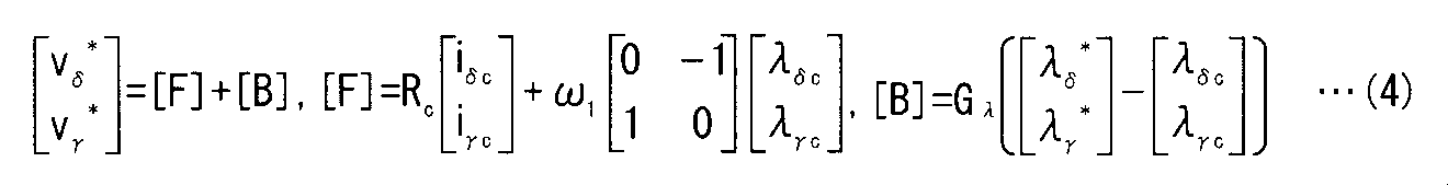
- the command value [ ⁇ * ] and ⁇ c is determined by the sum of the feedforward amount [F] and the feedback amount [B] in the following equation (4). Is done. However, the feedback gain G ⁇ ( ⁇ 0) and the ⁇ -axis component ⁇ ⁇ * and ⁇ -axis component ⁇ ⁇ * of the command value [ ⁇ * ] were introduced.
- the voltage command generation unit 1024 adds the feedforward amount [F] and the feedback amount [B] to obtain the voltage command [v ⁇ * ].
- the feedforward amount calculation unit 1023 inputs the gap magnetic flux [ ⁇ ⁇ c ] and the current [i ⁇ c ], and obtains the feedforward amount [F] according to Expression (4). That is, the feedforward amount [F] is obtained by a voltage equation in a steady state using the current [i ⁇ c ], the resistance component setting value R c , the rotational angular velocity ⁇ 1, and the air gap magnetic flux [ ⁇ ⁇ c ].
- the feedback amount calculation unit 1022 inputs the gap magnetic flux [ ⁇ ⁇ c ] and its command value [ ⁇ * ], and calculates the feedback amount [B] according to the equation (4). Specifically, the deviation between the command value [ ⁇ * ] and the gap magnetic flux [ ⁇ ⁇ c ] is multiplied by the feedback gain G ⁇ .
- the feedback gain G ⁇ can be stored in the feedback amount calculation unit 1022.
- the feedback gain G ⁇ is shown as a scalar quantity, but it may be a non-zero matrix of 2 rows and 2 columns that acts on the deviation of the air gap magnetic flux.
- the steady state represented by the equation (3) is realized by the control in the ⁇ c- ⁇ c rotating coordinate system.
- the voltage error [ ⁇ v ⁇ * ] is obtained by changing the voltage command [v ⁇ * ] from the voltage equation for the motor 3 (R c [i ⁇ c ] + (p [I] + ⁇ 1 [J]) [ ⁇ ⁇ c ])).
- the voltage error [ ⁇ v ⁇ * ] can be approximated by the second equation of equation (5).
- coefficient e iI, e iJ, e ⁇ , e v is the motor 3, the detector voltage supply 2, and the current [i x] (or the input voltage to the voltage supply source 2) each of (not shown) specifications of variations, as well as the rotational angular velocity omega 1, the manufacturing tolerance of the motor 3, varies within a range of fluctuation width determined by the guaranteed operating temperature range.
- the range in which the voltage error [ ⁇ v ⁇ * ], which is the error of the voltage command, fluctuates is the current [i ⁇ c ], the estimated phase angle ⁇ c , the voltage command [v ⁇ * ], and the coefficients e iI , e iJ , e ⁇ , also it depends on the variation width of the e v.
- the voltage error [ ⁇ v ⁇ * ] includes the current [i ⁇ c ], the voltage command [v ⁇ * ], the manufacturing tolerance of the motor 3 and the voltage supply source 2 and the guaranteed range of the operating temperature, and the current [i ⁇ c ].
- it is set based on the manufacturing tolerance of the detector that detects the voltage [v x ] and the guaranteed range of the operating temperature and the fluctuation range determined by at least one of the rotational angular velocities ⁇ 1 .
- the variation width of the current [i ⁇ c] and phase are parallel (in phase or opposite phase) and range errors e iI [I] in which [i ⁇ c] varies, the current [i ⁇ c] and The range in which the error e iJ [J] [i ⁇ c ] whose phase is orthogonal varies, the range in which the error e ⁇ [sin ⁇ c cos ⁇ c ] t is orthogonal to the field magnetic flux [ ⁇ 0 ], and the voltage command [ v [Delta] [gamma] *] the error e v whose phase parallel [v ⁇ *] is set at least one of the range varying.
- the voltage error [Delta] v [Delta] [gamma] *] it is premised that discrepancy between the actual phase angle phi and the estimated phase angle phi c is feedback-controlled to become smaller. And when the operation of the electric motor 3 is out of step, this premise is not satisfied. Therefore, in such a case, the feedback amount [B] exceeds the range in which the voltage error [ ⁇ v ⁇ * ] varies. In other words, it can be determined that the operation of the motor 3 has stepped out when the feedback amount [B] exceeds the range in which the voltage error [ ⁇ v ⁇ * ] fluctuates during feedback control.
- the range in which the voltage error [ ⁇ v ⁇ * ] varies serves as a threshold for the feedback amount [B] when determining the presence or absence of step-out.
- the voltage error calculator 1025 calculates the estimated phase angle ⁇ c , current [i ⁇ c ], and voltage command [v to calculate the range in which the voltage error [ ⁇ v ⁇ * ] varies according to the right side of the second expression of the equation (5). [ ⁇ * ]].
- coefficient e iI, e iJ, e ⁇ by using the upper and lower limits of the fluctuation range of e v, current [i ⁇ c], estimated phase angle phi c, a voltage command [v ⁇ *], formula (5)
- the maximum value and the minimum value of each term on the right side of the second equation are obtained.
- the voltage error [ ⁇ v ⁇ * ] when the combination of the maximum value or the minimum value of each term is adopted is compared with the feedback amount [B] using the threshold value as a threshold value.
- Coefficient e iI, e iJ, e ⁇ , e v may be calculated by the voltage error calculation unit 1025. In that case, the rotational angular velocity ⁇ 1 is also input to the voltage error calculation unit 1025.
- the range in which the voltage error [ ⁇ v ⁇ * ] fluctuates is the upper and lower limits of the fluctuation range, the maximum value of the voltage error [ ⁇ v ⁇ * ] in the combination of the current [i ⁇ c ] and the voltage command, or It can be understood that the value is set from the minimum value.
- the feedback amount [B] and the voltage error [ ⁇ v ⁇ * ] may be compared for each ⁇ c axis component and ⁇ c axis component. Or you may compare in only one of them. This is desirable from the viewpoint of reducing the amount of calculation.
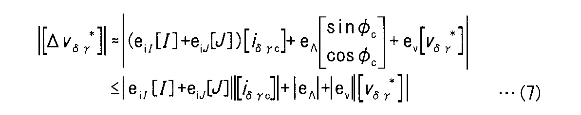
- Expression (8) obtains the maximum absolute value of the ⁇ c axis component ⁇ v ⁇ * of the voltage error [ ⁇ v ⁇ * ] compared with the feedback amount [B] in the ⁇ c axis component. Therefore, the rightmost side of the equation (8) may be compared with the feedback amount [B].
- the determination unit 109 receives the voltage error [ ⁇ v ⁇ * ], compares the threshold value or the voltage error [ ⁇ v ⁇ * ] as described above with the feedback amount [B], and outputs the determination signal Z.
- the determination unit 109 generates the above-described threshold value, but the voltage command calculation unit 102 may separately provide a block for obtaining the threshold value from the voltage error [ ⁇ v ⁇ * ].
- the voltage command output limiting unit 1026 inputs the determination signal Z and the voltage command [v ⁇ * ].
- the voltage command output limiting unit 1026 outputs a voltage command [v ⁇ * ] except when the determination signal Z indicates step-out.
- the voltage command output restriction unit 1026 outputs a stop command S instead of the voltage command [v ⁇ * ], and stops the operation of the voltage supply source 2. As a result, it is possible to avoid driving the electric motor 3 in a step-out state.
- an appropriate threshold value corresponding to the operating state is set. This is desirable from the viewpoint of increasing the accuracy of detecting step-out and reducing erroneous detection of step-out.
- the threshold value it is not necessary to experimentally determine the threshold value by setting the threshold value based on the fluctuation range determined by the manufacturing tolerance and the guaranteed range of the operation range. This is desirable from the standpoint that the development man-hours can be greatly reduced as compared with the method of determining the threshold on a trial basis.
- the second embodiment shows a technique for obtaining the feedback amount [B] from the deviation of current.
- the feedback amount [B] is obtained according to Equation (9).
- the feedback gain G i may be a non-zero matrix of 2 rows and 2 columns that acts on the current deviation.
- the configuration of the motor control device 1 according to this embodiment is different from the configuration of the motor control device 1 according to the first embodiment in that the voltage command calculation unit 102 uses the command value [ ⁇ ⁇ * ] of the air gap magnetic flux. The difference is that the current command value [i ⁇ * ] is input.
- FIG. 4 is a block diagram showing a configuration of the voltage command calculation unit 102 in the present embodiment.
- the voltage error [ ⁇ v ⁇ * ] can be determined in the same manner as in the first embodiment. Then, processing can be performed in the same manner as in the first embodiment to determine the presence or absence of step-out.
- the feedback amount [B] is calculated based on one of the current [i ⁇ c ] or the gap magnetic flux [ ⁇ ⁇ c ] and the command value ([i ⁇ * ], [ ⁇ ⁇ * ])).
- the voltage command [v ⁇ * ] is equal to the feedback amount [B].
- FIG. 5 is a block diagram showing a configuration of the voltage command calculation unit 102 in the present embodiment.
- the voltage command generation unit 1024 shown in the first embodiment and the second embodiment is not necessary, and the feedback amount [B] is output as the voltage command [v ⁇ * ] from the feedback amount calculation unit 1022.
- the feedforward amount calculation unit 1023 calculates the feedforward amount [F] as described in the first embodiment and the second embodiment. Then, the voltage error [ ⁇ v ⁇ * ] employed in the first and second embodiments is corrected by subtracting the feedforward amount [F] therefrom. In the present embodiment, the symbol [ ⁇ v ⁇ * ] is used for the voltage error corrected by subtracting the feedforward amount [F].
- the voltage error [ ⁇ v ⁇ * ] is obtained by the following equation (11).
- the step-out can be performed as in the first embodiment. Presence / absence can be determined. This is obvious from the equations (4) and (5).
- the product of the deviation and the feedback gain G i of the current is adopted as the feedback amount [B].
- the feedback amount [B] obtained by Expression (9) is adopted as the voltage command [v ⁇ * ]. Accordingly, as in the second embodiment, instead of inputting the gap magnetic flux [ ⁇ ⁇ c ] and its command value [ ⁇ ⁇ * ] to the feedback amount calculation unit 1022, the current [i ⁇ c ] and its command value [i [ ⁇ * ]].
- the voltage error [ ⁇ v ⁇ * ] is determined based on whether the feedback command [B] or only the feedforward amount [F] is included in determining the voltage command [v ⁇ * ]. Is different.
- the voltage error [ ⁇ v ⁇ * ] is set based on the feedforward amount [F] as in the present embodiment.
- the voltage error [ ⁇ v ⁇ * ] is not based on the gap magnetic flux [ ⁇ ⁇ c ] as in the first and second embodiments. (See Formula (5), Formula 2).
- the feedforward amount [F] may be set based on a term excluding some terms in the voltage equation. In this case, a range in which the voltage error [ ⁇ v ⁇ * ] fluctuates is set based on some of the terms.
- the coefficient e iI, e iJ, e ⁇ , e v is other variation of equipment constants of the motor 3, may also be affected by variations in the circuit.
- the coefficients e iI and e iJ are affected by variations in a detector (not shown) that detects the current [i x ], and the coefficient e v is input to a voltage control type inverter (not shown) of the voltage supply source 2. Or a detector (not shown) that detects the output voltage [v x ].
- these circuit variations have less influence on the voltage error [ ⁇ v ⁇ * ] than the device constant variation of the electric motor 3. Therefore, even if the variation on the circuit is ignored, it is practically possible to determine the step-out.
- the maximum value of the voltage error [ ⁇ v ⁇ * ], which is a threshold value compared with the feedback amount [B], may be calculated and stored in advance using the worst condition within the operation range assumed for the electric motor 3.
- the calculation amount of the voltage error calculation unit 1025 is small, and the required memory is small.
- the voltage error calculation unit 1025 can be substituted with a table that simply indicates threshold values.
- threshold values are obtained in advance for each rotation angular velocity, and these are stored as a table.
- the threshold value may be set larger than the maximum value of the voltage error [ ⁇ v ⁇ * ] in consideration of the margin.
- the threshold value may be obtained within a range in which the estimated phase angle ⁇ c can be assumed under the condition where no step-out occurs. For example, when the estimated phase angle ⁇ c is operated without step-out in the range of ⁇ 90 ° to 90 ° (such control is employed in, for example, primary magnetic flux control), ⁇ 1 ⁇ sin ⁇ c ⁇ 1, 0 ⁇
- the threshold value is obtained by using cos ⁇ c ⁇ 1.
- the threshold has the advantage that it can be determined that abnormality even when it becomes operational range of unexpected.
- each unit may be configured by hardware, or may be configured by a microcomputer (including a storage device) whose function is realized by software.
- Various procedures executed by each unit or various means or various functions implemented may be realized by hardware.
- the microcomputer executes each processing step (in other words, a procedure) described in the program.
- the storage device is composed of one or more of various storage devices such as a ROM (Read Only Memory), a RAM (Random Access Memory), a rewritable nonvolatile memory (EPROM (Erasable Programmable ROM), etc.), and a hard disk device, for example. Is possible.
- the storage device stores various information, data, and the like, stores a program executed by the microcomputer, and provides a work area for executing the program. It can be understood that the microcomputer functions as various means corresponding to each processing step described in the program, or can realize that various functions corresponding to each processing step are realized.
Landscapes
- Engineering & Computer Science (AREA)
- Power Engineering (AREA)
- Control Of Ac Motors In General (AREA)
Abstract
Description
実施の形態の詳細な説明に入る前に、この発明の基本的思想について説明する。もちろん、この基本的思想も本発明に含まれる。
図2は上記の考え方に基づいて、本実施の形態にかかる電動機制御装置1の構成及びその周辺装置を示すブロック図である。


第2の実施の形態ではフィードバック量[B]を電流の偏差から求める技術を示す。具体的には式(9)に従ってフィードバック量[B]を求める。但しフィードバックゲインGi(≠0)及び電流[iδγc]の指令値[iδγ *]=[iδ * iγ *]tを導入した。第1の実施の形態と同様、フィードバックゲインGiは電流の偏差に対して作用する2行2列の非零行列であってもよい。

本実施の形態ではフィードフォワード制御を用いずに、フィードバック制御のみを行う場合について示す。この場合、次式(10)で示されるように、電圧指令[vδγ *]はフィードバック量[B]と等しくなる。

上記係数eiI,eiJ,eΛ,evは、電動機3の機器定数のバラツキの他、回路上のバラツキの影響を受けることもあり得る。例えば係数eiI,eiJは電流[ix]を検出する検出器(不図示)のバラツキの影響を受け、係数evは電圧供給源2が有する電圧制御型インバータ(不図示)に入力される電圧もしくは出力する電圧[vx]を検出する検出器(不図示)のバラツキの影響を受ける。しかしながら、これらの回路上のバラツキは、電動機3の機器定数のバラツキと比較して電圧誤差[Δvδγ *]に与える影響は小さい。よって回路上のバラツキは無視しても、脱調を判定することは実際上、可能である。
フィードバック量[B]と比較される閾値たる電圧誤差[Δvδγ *]の最大値は、電動機3について想定される運転範囲内の最悪条件を用いて予め計算し、記憶していてもよい。
推定位相角φcは小さいので、これを零に近似して閾値を求めてもよい。
Claims (9)
- 同期電動機(3)を制御する装置であって、
電圧指令([vδγ *])に基づいて前記同期電動機に電圧([vx *])を印加する電動機駆動部(2,104)と、
前記同期電動機に流れる電流([iδγc])の、前記電流についての指令値([iδγ *])に対する偏差、若しくは、前記同期電動機における空隙磁束([λδγc])の、前記空隙磁束についての指令値([λδγ *])に対する偏差に基づくフィードバック量を決定するフィードバック量計算部(1022)と、
前記フィードバック量に基づいて前記電圧指令を生成する電圧指令生成部(1024)と、
前記同期電動機の電圧方程式に基づいた電圧値と前記電圧指令との誤差([Δvδγ *])が変動する範囲を計算する電圧誤差計算部(1025)と、
前記フィードバック量が前記誤差の変動する範囲を逸脱することを以て、前記同期電動機に異常が発生したと判定する判定部(109)と
を備える電動機の制御装置。 - 前記誤差([Δvδγ *])は、前記電流([iδγc])と、前記電圧指令([vδγ *])と、前記同期電動機(3)の製造公差及び動作温度の保証範囲と、前記電動機駆動部の製造公差及び動作温度の保証範囲と、前記電流または前記電圧を検出する検出器の製造公差及び動作温度の保証範囲と、前記同期電動機の回転角速度(ω1)のうちの少なくとも一つで決定される変動幅に基づいて設定される、請求項1記載の電動機の制御装置。
- 前記誤差([Δvδγ *])が変動する範囲は、前記電流([iδγc])と位相が平行する誤差(eiI[I][iδγc])が変動する範囲と、前記電流と位相が直交する誤差(eiJ[J][iδγc])が変動する範囲と、前記同期電動機(3)の界磁磁束([Λ0])と位相が直交する誤差(eΛ[sinφc cosφc]t)が変動する範囲と、前記電圧指令([vδγ *])と位相が平行する誤差(ev[vδγ *])が変動する範囲のうち少なくとも一つで決定される変動幅に基づいて設定される、請求項1記載の電動機の制御装置。
- 前記誤差([Δvδγ *])が変動する範囲は、前記電流([iδγc])と位相が平行する誤差(eiI[I][iδγc])が変動する範囲と、前記電流と位相が直交する誤差(eiJ[J][iδγc])が変動する範囲と、前記同期電動機(3)の界磁磁束([Λ0])と位相が直交する誤差(eΛ[sinφc cosφc]t)が変動する範囲と、前記電圧指令([vδγ *])と位相が平行する誤差(ev[vδγ *])が変動する範囲のうち少なくとも一つで決定される変動幅に基づいて設定される、請求項2記載の電動機の制御装置。
- 前記誤差([Δvδγ *])が変動する範囲は、前記変動幅の上限および下限、前記電流([iδγc])と前記電圧指令([vδγ *])との組み合わせにおける最大値または/および最小値より設定される、請求項2記載の電動機の制御装置。
- 前記誤差([Δvδγ *])が変動する範囲は、前記変動幅の上限および下限、前記電流([iδγc])と前記電圧指令([vδγ *])との組み合わせにおける最大値または/および最小値より設定される、請求項3記載の電動機の制御装置。
- 前記誤差([Δvδγ *])が変動する範囲は、前記変動幅の上限および下限、前記電流([iδγc])と前記電圧指令([vδγ *])との組み合わせにおける最大値または/および最小値より設定される、請求項4記載の電動機の制御装置。
- 前記誤差([Δvδγ *])が変動する範囲は、更に前記電圧方程式の一部の項にも基づいて設定され、
前記電圧方程式から前記一部の項を除いた項に基づくフィードフォワード量([F])を決定するフィードフォワード量計算部(1023)
を更に備え、
前記電圧指令生成部(1024)は、更に、前記フィードフォワード量にも基づいて前記電圧指令([vδγ *])を生成する、請求項1から請求項7のいずれか一つに記載の電動機の制御装置。 - 前記電圧方程式に基づくフィードフォワード量([F])を決定するフィードフォワード量計算部(1023)
を更に備え、
前記電圧指令生成部(1024)は、更に、前記フィードフォワード量([F])にも基づいて前記電圧指令([vδγ *])を生成する、請求項1から請求項7のいずれか一つに記載の電動機の制御装置。
Priority Applications (5)
| Application Number | Priority Date | Filing Date | Title |
|---|---|---|---|
| US15/105,159 US10298158B2 (en) | 2014-01-10 | 2015-01-06 | Controller for electric motor |
| EP15735188.3A EP3093985A4 (en) | 2014-01-10 | 2015-01-06 | Control device for electric motor |
| AU2015205227A AU2015205227B2 (en) | 2014-01-10 | 2015-01-06 | Controller for Electric Motor |
| KR1020167017594A KR101667908B1 (ko) | 2014-01-10 | 2015-01-06 | 전동기의 제어장치 |
| CN201580003046.1A CN105830336B (zh) | 2014-01-10 | 2015-01-06 | 电动机的控制装置 |
Applications Claiming Priority (2)
| Application Number | Priority Date | Filing Date | Title |
|---|---|---|---|
| JP2014003101A JP5854058B2 (ja) | 2014-01-10 | 2014-01-10 | 電動機の制御装置 |
| JP2014-003101 | 2014-01-10 |
Publications (1)
| Publication Number | Publication Date |
|---|---|
| WO2015105093A1 true WO2015105093A1 (ja) | 2015-07-16 |
Family
ID=53523918
Family Applications (1)
| Application Number | Title | Priority Date | Filing Date |
|---|---|---|---|
| PCT/JP2015/050120 WO2015105093A1 (ja) | 2014-01-10 | 2015-01-06 | 電動機の制御装置 |
Country Status (7)
| Country | Link |
|---|---|
| US (1) | US10298158B2 (ja) |
| EP (1) | EP3093985A4 (ja) |
| JP (1) | JP5854058B2 (ja) |
| KR (1) | KR101667908B1 (ja) |
| CN (1) | CN105830336B (ja) |
| AU (1) | AU2015205227B2 (ja) |
| WO (1) | WO2015105093A1 (ja) |
Families Citing this family (2)
| Publication number | Priority date | Publication date | Assignee | Title |
|---|---|---|---|---|
| KR102362338B1 (ko) * | 2014-02-28 | 2022-02-11 | 메르크 파텐트 게엠베하 | 유기 전계발광 소자용 재료 |
| JP2017051016A (ja) * | 2015-09-03 | 2017-03-09 | Ntn株式会社 | 車両用モータ駆動装置およびこれを搭載した車両 |
Citations (6)
| Publication number | Priority date | Publication date | Assignee | Title |
|---|---|---|---|---|
| JP2006067731A (ja) * | 2004-08-27 | 2006-03-09 | Mitsubishi Electric Corp | 電動パワーステアリング装置 |
| JP2008092787A (ja) | 2006-09-05 | 2008-04-17 | Mitsubishi Electric Corp | 電動機の駆動装置 |
| JP2008211911A (ja) * | 2007-02-26 | 2008-09-11 | Jtekt Corp | モータ制御装置及び電動パワーステアリング装置 |
| JP2010051151A (ja) | 2008-08-25 | 2010-03-04 | Jtekt Corp | モータ制御装置 |
| JP2010252503A (ja) | 2009-04-15 | 2010-11-04 | Meidensha Corp | Pmモータの位置・速度センサレス制御装置 |
| JP2013031356A (ja) * | 2011-06-24 | 2013-02-07 | Mitsubishi Electric Corp | モータ制御装置およびそれを用いた電動パワーステアリング装置 |
Family Cites Families (13)
| Publication number | Priority date | Publication date | Assignee | Title |
|---|---|---|---|---|
| US6281656B1 (en) * | 1998-09-30 | 2001-08-28 | Hitachi, Ltd. | Synchronous motor control device electric motor vehicle control device and method of controlling synchronous motor |
| JP4928850B2 (ja) * | 2006-06-28 | 2012-05-09 | 株式会社東芝 | 回転機制御装置 |
| JP4621997B2 (ja) * | 2006-07-10 | 2011-02-02 | 株式会社デンソー | 燃料ポンプの制御装置 |
| EP2075906A4 (en) * | 2006-10-19 | 2013-09-11 | Mitsubishi Electric Corp | VECTOR CONTROL OF A PERMANENT MAGNET SYNCHRONOUS MOTOR |
| JP5282376B2 (ja) * | 2007-06-29 | 2013-09-04 | 日本精工株式会社 | 電動パワーステアリング装置 |
| CN101884164B (zh) * | 2007-12-04 | 2013-02-27 | 三菱电机株式会社 | 交流电动机的控制装置 |
| JP5327700B2 (ja) * | 2008-10-02 | 2013-10-30 | 株式会社安川電機 | 誘導電動機の制御装置及びその制御方法 |
| JP5328592B2 (ja) * | 2009-10-02 | 2013-10-30 | オムロンオートモーティブエレクトロニクス株式会社 | モータ駆動装置 |
| JP5195888B2 (ja) * | 2010-06-24 | 2013-05-15 | 株式会社デンソー | 電動機駆動装置、および、これを用いた電動パワーステアリング装置 |
| JP5353867B2 (ja) * | 2010-12-02 | 2013-11-27 | 株式会社デンソー | 回転機の制御装置 |
| WO2012103941A2 (en) * | 2011-02-02 | 2012-08-09 | Telefonaktiebolaget L M Ericsson (Publ) | Digital control unit having a transient detector for controlling a switched mode power supply |
| JP5348153B2 (ja) * | 2011-02-14 | 2013-11-20 | 株式会社デンソー | 回転機の制御装置 |
| JP5880967B2 (ja) * | 2012-09-28 | 2016-03-09 | 株式会社デンソー | 交流電動機の制御装置 |
-
2014
- 2014-01-10 JP JP2014003101A patent/JP5854058B2/ja active Active
-
2015
- 2015-01-06 AU AU2015205227A patent/AU2015205227B2/en active Active
- 2015-01-06 KR KR1020167017594A patent/KR101667908B1/ko active IP Right Grant
- 2015-01-06 CN CN201580003046.1A patent/CN105830336B/zh active Active
- 2015-01-06 EP EP15735188.3A patent/EP3093985A4/en active Pending
- 2015-01-06 US US15/105,159 patent/US10298158B2/en active Active
- 2015-01-06 WO PCT/JP2015/050120 patent/WO2015105093A1/ja active Application Filing
Patent Citations (6)
| Publication number | Priority date | Publication date | Assignee | Title |
|---|---|---|---|---|
| JP2006067731A (ja) * | 2004-08-27 | 2006-03-09 | Mitsubishi Electric Corp | 電動パワーステアリング装置 |
| JP2008092787A (ja) | 2006-09-05 | 2008-04-17 | Mitsubishi Electric Corp | 電動機の駆動装置 |
| JP2008211911A (ja) * | 2007-02-26 | 2008-09-11 | Jtekt Corp | モータ制御装置及び電動パワーステアリング装置 |
| JP2010051151A (ja) | 2008-08-25 | 2010-03-04 | Jtekt Corp | モータ制御装置 |
| JP2010252503A (ja) | 2009-04-15 | 2010-11-04 | Meidensha Corp | Pmモータの位置・速度センサレス制御装置 |
| JP2013031356A (ja) * | 2011-06-24 | 2013-02-07 | Mitsubishi Electric Corp | モータ制御装置およびそれを用いた電動パワーステアリング装置 |
Non-Patent Citations (1)
| Title |
|---|
| See also references of EP3093985A4 |
Also Published As
| Publication number | Publication date |
|---|---|
| US10298158B2 (en) | 2019-05-21 |
| KR101667908B1 (ko) | 2016-10-19 |
| EP3093985A1 (en) | 2016-11-16 |
| CN105830336B (zh) | 2019-11-26 |
| CN105830336A (zh) | 2016-08-03 |
| KR20160085903A (ko) | 2016-07-18 |
| JP5854058B2 (ja) | 2016-02-09 |
| JP2015133794A (ja) | 2015-07-23 |
| US20170005603A1 (en) | 2017-01-05 |
| AU2015205227B2 (en) | 2017-08-31 |
| AU2015205227A1 (en) | 2016-06-30 |
| EP3093985A4 (en) | 2018-01-03 |
Similar Documents
| Publication | Publication Date | Title |
|---|---|---|
| JP5494760B2 (ja) | 電動機制御装置 | |
| JP4502734B2 (ja) | 電動機の回転位置検出装置の原点オフセット量算出方法およびこの算出方法を用いた電動機制御装置 | |
| JP5073063B2 (ja) | 永久磁石同期電動機の制御装置 | |
| JP5800108B2 (ja) | 周期外乱自動抑制装置 | |
| JP2011004506A (ja) | モータ制御装置 | |
| JPWO2016121373A1 (ja) | モータ制御装置、およびこのモータ制御装置におけるトルク定数の補正方法 | |
| JP2010029028A (ja) | モータ制御装置 | |
| JP2016082790A (ja) | 電動機制御装置、電動機制御システム | |
| JP2007135345A (ja) | 磁石モータ制御装置 | |
| JP5854058B2 (ja) | 電動機の制御装置 | |
| JP5660191B2 (ja) | 電動機制御装置 | |
| JP2004120834A (ja) | Dcブラシレスモータの制御装置 | |
| CN110635737A (zh) | 电机驱动装置 | |
| JP4667741B2 (ja) | 誘導電動機の制御装置 | |
| JP5862690B2 (ja) | 電動機駆動装置の制御装置および電動機駆動システム | |
| JP2014158336A (ja) | モータ制御装置 | |
| JP7035818B2 (ja) | 巻線界磁型同期モータの制御方法、及び、制御装置 | |
| JP5862691B2 (ja) | 電動機駆動装置の制御装置および電動機駆動システム | |
| JP5983352B2 (ja) | 電動機制御装置 | |
| JP5854057B2 (ja) | 脱調検出装置および電動機駆動システム | |
| JP6582393B2 (ja) | 電動機駆動装置の制御装置 | |
| JP5983636B2 (ja) | 電動機の制御装置 | |
| JP6015647B2 (ja) | 電動機駆動装置の制御装置及び電動機駆動システム | |
| JP6464559B2 (ja) | 電動機の制御装置 | |
| JP5846195B2 (ja) | 電動機駆動装置の制御装置および電動機駆動システム |
Legal Events
| Date | Code | Title | Description |
|---|---|---|---|
| 121 | Ep: the epo has been informed by wipo that ep was designated in this application |
Ref document number: 15735188 Country of ref document: EP Kind code of ref document: A1 |
|
| REEP | Request for entry into the european phase |
Ref document number: 2015735188 Country of ref document: EP |
|
| WWE | Wipo information: entry into national phase |
Ref document number: 2015735188 Country of ref document: EP |
|
| WWE | Wipo information: entry into national phase |
Ref document number: 15105159 Country of ref document: US |
|
| ENP | Entry into the national phase |
Ref document number: 2015205227 Country of ref document: AU Date of ref document: 20150106 Kind code of ref document: A Ref document number: 20167017594 Country of ref document: KR Kind code of ref document: A |
|
| NENP | Non-entry into the national phase |
Ref country code: DE |