WO2015104964A1 - 電池用セパレータ及びその製造方法 - Google Patents
電池用セパレータ及びその製造方法 Download PDFInfo
- Publication number
- WO2015104964A1 WO2015104964A1 PCT/JP2014/083302 JP2014083302W WO2015104964A1 WO 2015104964 A1 WO2015104964 A1 WO 2015104964A1 JP 2014083302 W JP2014083302 W JP 2014083302W WO 2015104964 A1 WO2015104964 A1 WO 2015104964A1
- Authority
- WO
- WIPO (PCT)
- Prior art keywords
- polyethylene
- battery separator
- polyolefin
- porous membrane
- weight
- Prior art date
Links
- 238000004519 manufacturing process Methods 0.000 title claims description 13
- 239000012528 membrane Substances 0.000 claims abstract description 94
- 229920000098 polyolefin Polymers 0.000 claims abstract description 71
- 229920005989 resin Polymers 0.000 claims abstract description 37
- 239000011347 resin Substances 0.000 claims abstract description 37
- 239000010954 inorganic particle Substances 0.000 claims abstract description 28
- YCKRFDGAMUMZLT-UHFFFAOYSA-N Fluorine atom Chemical compound [F] YCKRFDGAMUMZLT-UHFFFAOYSA-N 0.000 claims abstract description 16
- 239000011737 fluorine Substances 0.000 claims abstract description 16
- 229910052731 fluorine Inorganic materials 0.000 claims abstract description 16
- 238000001816 cooling Methods 0.000 claims description 55
- 239000002904 solvent Substances 0.000 claims description 55
- 229920013716 polyethylene resin Polymers 0.000 claims description 39
- 238000000465 moulding Methods 0.000 claims description 31
- PNEYBMLMFCGWSK-UHFFFAOYSA-N aluminium oxide Inorganic materials [O-2].[O-2].[O-2].[Al+3].[Al+3] PNEYBMLMFCGWSK-UHFFFAOYSA-N 0.000 claims description 14
- 238000000576 coating method Methods 0.000 claims description 10
- 238000004898 kneading Methods 0.000 claims description 10
- 238000001035 drying Methods 0.000 claims description 9
- HBBGRARXTFLTSG-UHFFFAOYSA-N Lithium ion Chemical compound [Li+] HBBGRARXTFLTSG-UHFFFAOYSA-N 0.000 claims description 8
- 239000011248 coating agent Substances 0.000 claims description 8
- 229910001416 lithium ion Inorganic materials 0.000 claims description 8
- GWEVSGVZZGPLCZ-UHFFFAOYSA-N Titan oxide Chemical compound O=[Ti]=O GWEVSGVZZGPLCZ-UHFFFAOYSA-N 0.000 claims description 7
- VTYYLEPIZMXCLO-UHFFFAOYSA-L Calcium carbonate Chemical compound [Ca+2].[O-]C([O-])=O VTYYLEPIZMXCLO-UHFFFAOYSA-L 0.000 claims description 6
- TZCXTZWJZNENPQ-UHFFFAOYSA-L barium sulfate Chemical compound [Ba+2].[O-]S([O-])(=O)=O TZCXTZWJZNENPQ-UHFFFAOYSA-L 0.000 claims description 6
- FAHBNUUHRFUEAI-UHFFFAOYSA-M hydroxidooxidoaluminium Chemical compound O[Al]=O FAHBNUUHRFUEAI-UHFFFAOYSA-M 0.000 claims description 6
- 229910001593 boehmite Inorganic materials 0.000 claims description 4
- 229910000019 calcium carbonate Inorganic materials 0.000 claims description 3
- 238000012545 processing Methods 0.000 abstract description 14
- -1 polyethylene Polymers 0.000 description 78
- 239000010410 layer Substances 0.000 description 75
- 239000004698 Polyethylene Substances 0.000 description 71
- 229920000573 polyethylene Polymers 0.000 description 71
- 238000000034 method Methods 0.000 description 57
- 239000000243 solution Substances 0.000 description 41
- 239000002245 particle Substances 0.000 description 36
- 239000000203 mixture Substances 0.000 description 27
- SECXISVLQFMRJM-UHFFFAOYSA-N N-Methylpyrrolidone Chemical compound CN1CCCC1=O SECXISVLQFMRJM-UHFFFAOYSA-N 0.000 description 18
- 229910052782 aluminium Inorganic materials 0.000 description 18
- XAGFODPZIPBFFR-UHFFFAOYSA-N aluminium Chemical compound [Al] XAGFODPZIPBFFR-UHFFFAOYSA-N 0.000 description 18
- 229920001903 high density polyethylene Polymers 0.000 description 17
- 239000004700 high-density polyethylene Substances 0.000 description 17
- 229920005672 polyolefin resin Polymers 0.000 description 14
- 239000011148 porous material Substances 0.000 description 14
- 239000002966 varnish Substances 0.000 description 14
- 230000035699 permeability Effects 0.000 description 13
- 230000008569 process Effects 0.000 description 13
- 230000000052 comparative effect Effects 0.000 description 12
- 229940057995 liquid paraffin Drugs 0.000 description 11
- 238000002844 melting Methods 0.000 description 11
- 230000008018 melting Effects 0.000 description 11
- 238000004140 cleaning Methods 0.000 description 9
- 230000000694 effects Effects 0.000 description 9
- 238000010438 heat treatment Methods 0.000 description 9
- 229920002981 polyvinylidene fluoride Polymers 0.000 description 9
- 239000002033 PVDF binder Substances 0.000 description 8
- 239000003792 electrolyte Substances 0.000 description 8
- 239000004699 Ultra-high molecular weight polyethylene Substances 0.000 description 7
- 239000013078 crystal Substances 0.000 description 7
- 238000001125 extrusion Methods 0.000 description 7
- 239000007787 solid Substances 0.000 description 7
- 229920000785 ultra high molecular weight polyethylene Polymers 0.000 description 7
- XLYOFNOQVPJJNP-UHFFFAOYSA-N water Substances O XLYOFNOQVPJJNP-UHFFFAOYSA-N 0.000 description 7
- YMWUJEATGCHHMB-UHFFFAOYSA-N Dichloromethane Chemical compound ClCCl YMWUJEATGCHHMB-UHFFFAOYSA-N 0.000 description 6
- 239000004743 Polypropylene Substances 0.000 description 6
- 238000011156 evaluation Methods 0.000 description 6
- 239000000463 material Substances 0.000 description 6
- 229920001155 polypropylene Polymers 0.000 description 6
- BQCIDUSAKPWEOX-UHFFFAOYSA-N 1,1-Difluoroethene Chemical compound FC(F)=C BQCIDUSAKPWEOX-UHFFFAOYSA-N 0.000 description 5
- 229920006369 KF polymer Polymers 0.000 description 5
- 229920010741 Ultra High Molecular Weight Polyethylene (UHMWPE) Polymers 0.000 description 5
- 230000000903 blocking effect Effects 0.000 description 5
- 238000002425 crystallisation Methods 0.000 description 5
- 230000008025 crystallization Effects 0.000 description 5
- 229920001519 homopolymer Polymers 0.000 description 5
- 238000010030 laminating Methods 0.000 description 5
- 239000007788 liquid Substances 0.000 description 5
- 239000012982 microporous membrane Substances 0.000 description 5
- 238000002156 mixing Methods 0.000 description 5
- 229920000642 polymer Polymers 0.000 description 5
- 239000000126 substance Substances 0.000 description 5
- 229920006370 Kynar Polymers 0.000 description 4
- 239000004962 Polyamide-imide Substances 0.000 description 4
- 230000002159 abnormal effect Effects 0.000 description 4
- 239000002390 adhesive tape Substances 0.000 description 4
- 239000003963 antioxidant agent Substances 0.000 description 4
- 230000003078 antioxidant effect Effects 0.000 description 4
- 239000011324 bead Substances 0.000 description 4
- 238000005345 coagulation Methods 0.000 description 4
- 230000015271 coagulation Effects 0.000 description 4
- 239000011247 coating layer Substances 0.000 description 4
- 239000000498 cooling water Substances 0.000 description 4
- 238000009826 distribution Methods 0.000 description 4
- 238000009413 insulation Methods 0.000 description 4
- 238000003475 lamination Methods 0.000 description 4
- 229920001684 low density polyethylene Polymers 0.000 description 4
- 239000004702 low-density polyethylene Substances 0.000 description 4
- 238000005259 measurement Methods 0.000 description 4
- 229920001179 medium density polyethylene Polymers 0.000 description 4
- 239000004701 medium-density polyethylene Substances 0.000 description 4
- 229920002312 polyamide-imide Polymers 0.000 description 4
- 229920000728 polyester Polymers 0.000 description 4
- 238000005096 rolling process Methods 0.000 description 4
- 238000005406 washing Methods 0.000 description 4
- RTZKZFJDLAIYFH-UHFFFAOYSA-N Diethyl ether Chemical compound CCOCC RTZKZFJDLAIYFH-UHFFFAOYSA-N 0.000 description 3
- 229920006368 Hylar Polymers 0.000 description 3
- 238000006243 chemical reaction Methods 0.000 description 3
- 230000007547 defect Effects 0.000 description 3
- 238000001914 filtration Methods 0.000 description 3
- 230000010220 ion permeability Effects 0.000 description 3
- VLKZOEOYAKHREP-UHFFFAOYSA-N n-Hexane Chemical compound CCCCCC VLKZOEOYAKHREP-UHFFFAOYSA-N 0.000 description 3
- 238000005191 phase separation Methods 0.000 description 3
- 238000012546 transfer Methods 0.000 description 3
- VXNZUUAINFGPBY-UHFFFAOYSA-N 1-Butene Chemical compound CCC=C VXNZUUAINFGPBY-UHFFFAOYSA-N 0.000 description 2
- LIKMAJRDDDTEIG-UHFFFAOYSA-N 1-hexene Chemical compound CCCCC=C LIKMAJRDDDTEIG-UHFFFAOYSA-N 0.000 description 2
- KWKAKUADMBZCLK-UHFFFAOYSA-N 1-octene Chemical compound CCCCCCC=C KWKAKUADMBZCLK-UHFFFAOYSA-N 0.000 description 2
- WSSSPWUEQFSQQG-UHFFFAOYSA-N 4-methyl-1-pentene Chemical compound CC(C)CC=C WSSSPWUEQFSQQG-UHFFFAOYSA-N 0.000 description 2
- 239000005995 Aluminium silicate Substances 0.000 description 2
- 229920000089 Cyclic olefin copolymer Polymers 0.000 description 2
- VGGSQFUCUMXWEO-UHFFFAOYSA-N Ethene Chemical compound C=C VGGSQFUCUMXWEO-UHFFFAOYSA-N 0.000 description 2
- 239000005977 Ethylene Substances 0.000 description 2
- CERQOIWHTDAKMF-UHFFFAOYSA-N Methacrylic acid Chemical compound CC(=C)C(O)=O CERQOIWHTDAKMF-UHFFFAOYSA-N 0.000 description 2
- IMNFDUFMRHMDMM-UHFFFAOYSA-N N-Heptane Chemical compound CCCCCCC IMNFDUFMRHMDMM-UHFFFAOYSA-N 0.000 description 2
- OFBQJSOFQDEBGM-UHFFFAOYSA-N Pentane Chemical compound CCCCC OFBQJSOFQDEBGM-UHFFFAOYSA-N 0.000 description 2
- 239000004820 Pressure-sensitive adhesive Substances 0.000 description 2
- PPBRXRYQALVLMV-UHFFFAOYSA-N Styrene Chemical compound C=CC1=CC=CC=C1 PPBRXRYQALVLMV-UHFFFAOYSA-N 0.000 description 2
- 239000011149 active material Substances 0.000 description 2
- 239000000853 adhesive Substances 0.000 description 2
- 230000001070 adhesive effect Effects 0.000 description 2
- 235000012211 aluminium silicate Nutrition 0.000 description 2
- 239000007864 aqueous solution Substances 0.000 description 2
- 238000007611 bar coating method Methods 0.000 description 2
- 239000011230 binding agent Substances 0.000 description 2
- OJIJEKBXJYRIBZ-UHFFFAOYSA-N cadmium nickel Chemical compound [Ni].[Cd] OJIJEKBXJYRIBZ-UHFFFAOYSA-N 0.000 description 2
- 239000002131 composite material Substances 0.000 description 2
- 238000009833 condensation Methods 0.000 description 2
- 230000005494 condensation Effects 0.000 description 2
- 230000008602 contraction Effects 0.000 description 2
- 229920001577 copolymer Polymers 0.000 description 2
- 238000003851 corona treatment Methods 0.000 description 2
- 238000012937 correction Methods 0.000 description 2
- NNBZCPXTIHJBJL-UHFFFAOYSA-N decalin Chemical compound C1CCCC2CCCCC21 NNBZCPXTIHJBJL-UHFFFAOYSA-N 0.000 description 2
- DIOQZVSQGTUSAI-UHFFFAOYSA-N decane Chemical compound CCCCCCCCCC DIOQZVSQGTUSAI-UHFFFAOYSA-N 0.000 description 2
- 238000003618 dip coating Methods 0.000 description 2
- 238000004090 dissolution Methods 0.000 description 2
- SNRUBQQJIBEYMU-UHFFFAOYSA-N dodecane Chemical compound CCCCCCCCCCCC SNRUBQQJIBEYMU-UHFFFAOYSA-N 0.000 description 2
- 238000010292 electrical insulation Methods 0.000 description 2
- 239000007772 electrode material Substances 0.000 description 2
- 238000004049 embossing Methods 0.000 description 2
- XUCNUKMRBVNAPB-UHFFFAOYSA-N fluoroethene Chemical compound FC=C XUCNUKMRBVNAPB-UHFFFAOYSA-N 0.000 description 2
- 239000011521 glass Substances 0.000 description 2
- 238000009499 grossing Methods 0.000 description 2
- 229930195733 hydrocarbon Natural products 0.000 description 2
- 150000002430 hydrocarbons Chemical class 0.000 description 2
- 239000001257 hydrogen Substances 0.000 description 2
- 229910052739 hydrogen Inorganic materials 0.000 description 2
- NLYAJNPCOHFWQQ-UHFFFAOYSA-N kaolin Chemical compound O.O.O=[Al]O[Si](=O)O[Si](=O)O[Al]=O NLYAJNPCOHFWQQ-UHFFFAOYSA-N 0.000 description 2
- PQXKHYXIUOZZFA-UHFFFAOYSA-M lithium fluoride Chemical compound [Li+].[F-] PQXKHYXIUOZZFA-UHFFFAOYSA-M 0.000 description 2
- 229910052751 metal Inorganic materials 0.000 description 2
- 239000002184 metal Substances 0.000 description 2
- 239000007773 negative electrode material Substances 0.000 description 2
- BKIMMITUMNQMOS-UHFFFAOYSA-N nonane Chemical compound CCCCCCCCC BKIMMITUMNQMOS-UHFFFAOYSA-N 0.000 description 2
- 239000011255 nonaqueous electrolyte Substances 0.000 description 2
- 230000003647 oxidation Effects 0.000 description 2
- 238000007254 oxidation reaction Methods 0.000 description 2
- RVTZCBVAJQQJTK-UHFFFAOYSA-N oxygen(2-);zirconium(4+) Chemical compound [O-2].[O-2].[Zr+4] RVTZCBVAJQQJTK-UHFFFAOYSA-N 0.000 description 2
- 239000003973 paint Substances 0.000 description 2
- YWAKXRMUMFPDSH-UHFFFAOYSA-N pentene Chemical compound CCCC=C YWAKXRMUMFPDSH-UHFFFAOYSA-N 0.000 description 2
- NROKBHXJSPEDAR-UHFFFAOYSA-M potassium fluoride Chemical compound [F-].[K+] NROKBHXJSPEDAR-UHFFFAOYSA-M 0.000 description 2
- 230000009467 reduction Effects 0.000 description 2
- 230000004044 response Effects 0.000 description 2
- 230000000717 retained effect Effects 0.000 description 2
- 238000000926 separation method Methods 0.000 description 2
- VZGDMQKNWNREIO-UHFFFAOYSA-N tetrachloromethane Chemical compound ClC(Cl)(Cl)Cl VZGDMQKNWNREIO-UHFFFAOYSA-N 0.000 description 2
- 229920005992 thermoplastic resin Polymers 0.000 description 2
- DVKJHBMWWAPEIU-UHFFFAOYSA-N toluene 2,4-diisocyanate Chemical compound CC1=CC=C(N=C=O)C=C1N=C=O DVKJHBMWWAPEIU-UHFFFAOYSA-N 0.000 description 2
- SRPWOOOHEPICQU-UHFFFAOYSA-N trimellitic anhydride Chemical compound OC(=O)C1=CC=C2C(=O)OC(=O)C2=C1 SRPWOOOHEPICQU-UHFFFAOYSA-N 0.000 description 2
- RSJKGSCJYJTIGS-UHFFFAOYSA-N undecane Chemical compound CCCCCCCCCCC RSJKGSCJYJTIGS-UHFFFAOYSA-N 0.000 description 2
- 229910001928 zirconium oxide Inorganic materials 0.000 description 2
- 239000004711 α-olefin Substances 0.000 description 2
- RYHBNJHYFVUHQT-UHFFFAOYSA-N 1,4-Dioxane Chemical compound C1COCCO1 RYHBNJHYFVUHQT-UHFFFAOYSA-N 0.000 description 1
- WPMYUUITDBHVQZ-UHFFFAOYSA-M 3-(3,5-ditert-butyl-4-hydroxyphenyl)propanoate Chemical compound CC(C)(C)C1=CC(CCC([O-])=O)=CC(C(C)(C)C)=C1O WPMYUUITDBHVQZ-UHFFFAOYSA-M 0.000 description 1
- 239000004925 Acrylic resin Substances 0.000 description 1
- 229920000178 Acrylic resin Polymers 0.000 description 1
- IJGRMHOSHXDMSA-UHFFFAOYSA-N Atomic nitrogen Chemical compound N#N IJGRMHOSHXDMSA-UHFFFAOYSA-N 0.000 description 1
- 238000012935 Averaging Methods 0.000 description 1
- XKGKLYUXFRFGKU-UHFFFAOYSA-N CC.F.F.F Chemical compound CC.F.F.F XKGKLYUXFRFGKU-UHFFFAOYSA-N 0.000 description 1
- VYZAMTAEIAYCRO-UHFFFAOYSA-N Chromium Chemical compound [Cr] VYZAMTAEIAYCRO-UHFFFAOYSA-N 0.000 description 1
- KRHYYFGTRYWZRS-UHFFFAOYSA-M Fluoride anion Chemical compound [F-] KRHYYFGTRYWZRS-UHFFFAOYSA-M 0.000 description 1
- WHXSMMKQMYFTQS-UHFFFAOYSA-N Lithium Chemical compound [Li] WHXSMMKQMYFTQS-UHFFFAOYSA-N 0.000 description 1
- 229930182556 Polyacetal Natural products 0.000 description 1
- 239000004372 Polyvinyl alcohol Substances 0.000 description 1
- 241000135309 Processus Species 0.000 description 1
- 229910021536 Zeolite Inorganic materials 0.000 description 1
- 239000011954 Ziegler–Natta catalyst Substances 0.000 description 1
- 238000005299 abrasion Methods 0.000 description 1
- 238000007605 air drying Methods 0.000 description 1
- 238000007754 air knife coating Methods 0.000 description 1
- 125000001931 aliphatic group Chemical group 0.000 description 1
- 150000001336 alkenes Chemical class 0.000 description 1
- 239000004760 aramid Substances 0.000 description 1
- 229920003235 aromatic polyamide Polymers 0.000 description 1
- 230000015572 biosynthetic process Effects 0.000 description 1
- 238000007664 blowing Methods 0.000 description 1
- 238000009835 boiling Methods 0.000 description 1
- 238000005219 brazing Methods 0.000 description 1
- 230000005587 bubbling Effects 0.000 description 1
- WUKWITHWXAAZEY-UHFFFAOYSA-L calcium difluoride Chemical compound [F-].[F-].[Ca+2] WUKWITHWXAAZEY-UHFFFAOYSA-L 0.000 description 1
- JUNWLZAGQLJVLR-UHFFFAOYSA-J calcium diphosphate Chemical compound [Ca+2].[Ca+2].[O-]P([O-])(=O)OP([O-])([O-])=O JUNWLZAGQLJVLR-UHFFFAOYSA-J 0.000 description 1
- 229910001634 calcium fluoride Inorganic materials 0.000 description 1
- 239000003990 capacitor Substances 0.000 description 1
- 210000004027 cell Anatomy 0.000 description 1
- 230000008859 change Effects 0.000 description 1
- 150000008280 chlorinated hydrocarbons Chemical class 0.000 description 1
- 238000004891 communication Methods 0.000 description 1
- 239000000470 constituent Substances 0.000 description 1
- 238000004132 cross linking Methods 0.000 description 1
- 125000000753 cycloalkyl group Chemical group 0.000 description 1
- 210000001787 dendrite Anatomy 0.000 description 1
- 238000007607 die coating method Methods 0.000 description 1
- 238000000113 differential scanning calorimetry Methods 0.000 description 1
- 238000007865 diluting Methods 0.000 description 1
- 229910001873 dinitrogen Inorganic materials 0.000 description 1
- HNPSIPDUKPIQMN-UHFFFAOYSA-N dioxosilane;oxo(oxoalumanyloxy)alumane Chemical compound O=[Si]=O.O=[Al]O[Al]=O HNPSIPDUKPIQMN-UHFFFAOYSA-N 0.000 description 1
- 239000006185 dispersion Substances 0.000 description 1
- 229920001971 elastomer Polymers 0.000 description 1
- 239000008151 electrolyte solution Substances 0.000 description 1
- 238000005516 engineering process Methods 0.000 description 1
- 150000002148 esters Chemical class 0.000 description 1
- 125000002573 ethenylidene group Chemical group [*]=C=C([H])[H] 0.000 description 1
- 150000002170 ethers Chemical class 0.000 description 1
- 235000012438 extruded product Nutrition 0.000 description 1
- 239000004744 fabric Substances 0.000 description 1
- 239000000945 filler Substances 0.000 description 1
- 239000010419 fine particle Substances 0.000 description 1
- 238000005187 foaming Methods 0.000 description 1
- 238000007429 general method Methods 0.000 description 1
- 238000007756 gravure coating Methods 0.000 description 1
- 229920006015 heat resistant resin Polymers 0.000 description 1
- 238000007602 hot air drying Methods 0.000 description 1
- 238000007654 immersion Methods 0.000 description 1
- 238000005470 impregnation Methods 0.000 description 1
- 230000006872 improvement Effects 0.000 description 1
- 239000011261 inert gas Substances 0.000 description 1
- 239000011229 interlayer Substances 0.000 description 1
- 238000002955 isolation Methods 0.000 description 1
- 238000007759 kiss coating Methods 0.000 description 1
- 239000004816 latex Substances 0.000 description 1
- 229920000126 latex Polymers 0.000 description 1
- 229910052744 lithium Inorganic materials 0.000 description 1
- 239000011159 matrix material Substances 0.000 description 1
- 230000007246 mechanism Effects 0.000 description 1
- 239000012567 medical material Substances 0.000 description 1
- 239000012968 metallocene catalyst Substances 0.000 description 1
- 238000007760 metering rod coating Methods 0.000 description 1
- 239000010445 mica Substances 0.000 description 1
- 229910052618 mica group Inorganic materials 0.000 description 1
- 238000001471 micro-filtration Methods 0.000 description 1
- 239000002480 mineral oil Substances 0.000 description 1
- 235000010446 mineral oil Nutrition 0.000 description 1
- 239000012046 mixed solvent Substances 0.000 description 1
- CWQXQMHSOZUFJS-UHFFFAOYSA-N molybdenum disulfide Chemical compound S=[Mo]=S CWQXQMHSOZUFJS-UHFFFAOYSA-N 0.000 description 1
- TVMXDCGIABBOFY-UHFFFAOYSA-N n-Octanol Natural products CCCCCCCC TVMXDCGIABBOFY-UHFFFAOYSA-N 0.000 description 1
- QELJHCBNGDEXLD-UHFFFAOYSA-N nickel zinc Chemical compound [Ni].[Zn] QELJHCBNGDEXLD-UHFFFAOYSA-N 0.000 description 1
- 239000003921 oil Substances 0.000 description 1
- 230000035515 penetration Effects 0.000 description 1
- 230000000737 periodic effect Effects 0.000 description 1
- 239000011990 phillips catalyst Substances 0.000 description 1
- 238000007747 plating Methods 0.000 description 1
- 229920005569 poly(vinylidene fluoride-co-hexafluoropropylene) Polymers 0.000 description 1
- 229920006122 polyamide resin Polymers 0.000 description 1
- 229920001721 polyimide Polymers 0.000 description 1
- 239000009719 polyimide resin Substances 0.000 description 1
- 229920002959 polymer blend Polymers 0.000 description 1
- 239000002685 polymerization catalyst Substances 0.000 description 1
- 238000006116 polymerization reaction Methods 0.000 description 1
- 229920006324 polyoxymethylene Polymers 0.000 description 1
- 229920002451 polyvinyl alcohol Polymers 0.000 description 1
- 239000011698 potassium fluoride Substances 0.000 description 1
- 235000003270 potassium fluoride Nutrition 0.000 description 1
- 239000000843 powder Substances 0.000 description 1
- 230000002265 prevention Effects 0.000 description 1
- QQONPFPTGQHPMA-UHFFFAOYSA-N propylene Natural products CC=C QQONPFPTGQHPMA-UHFFFAOYSA-N 0.000 description 1
- 125000004805 propylene group Chemical group [H]C([H])([H])C([H])([*:1])C([H])([H])[*:2] 0.000 description 1
- 238000010791 quenching Methods 0.000 description 1
- 230000000171 quenching effect Effects 0.000 description 1
- 238000001953 recrystallisation Methods 0.000 description 1
- 239000003507 refrigerant Substances 0.000 description 1
- 239000013557 residual solvent Substances 0.000 description 1
- 238000001223 reverse osmosis Methods 0.000 description 1
- 238000007763 reverse roll coating Methods 0.000 description 1
- 230000000630 rising effect Effects 0.000 description 1
- 238000007790 scraping Methods 0.000 description 1
- 239000000377 silicon dioxide Substances 0.000 description 1
- VYPSYNLAJGMNEJ-UHFFFAOYSA-N silicon dioxide Inorganic materials O=[Si]=O VYPSYNLAJGMNEJ-UHFFFAOYSA-N 0.000 description 1
- BSWGGJHLVUUXTL-UHFFFAOYSA-N silver zinc Chemical compound [Zn].[Ag] BSWGGJHLVUUXTL-UHFFFAOYSA-N 0.000 description 1
- 239000002356 single layer Substances 0.000 description 1
- 238000005245 sintering Methods 0.000 description 1
- 238000005507 spraying Methods 0.000 description 1
- 230000000087 stabilizing effect Effects 0.000 description 1
- 238000003756 stirring Methods 0.000 description 1
- 230000003746 surface roughness Effects 0.000 description 1
- 239000000454 talc Substances 0.000 description 1
- 229910052623 talc Inorganic materials 0.000 description 1
- 239000004408 titanium dioxide Substances 0.000 description 1
- OGIDPMRJRNCKJF-UHFFFAOYSA-N titanium oxide Inorganic materials [Ti]=O OGIDPMRJRNCKJF-UHFFFAOYSA-N 0.000 description 1
- 238000000108 ultra-filtration Methods 0.000 description 1
- 238000001291 vacuum drying Methods 0.000 description 1
- PXXNTAGJWPJAGM-UHFFFAOYSA-N vertaline Natural products C1C2C=3C=C(OC)C(OC)=CC=3OC(C=C3)=CC=C3CCC(=O)OC1CC1N2CCCC1 PXXNTAGJWPJAGM-UHFFFAOYSA-N 0.000 description 1
- 238000004804 winding Methods 0.000 description 1
- 239000010457 zeolite Substances 0.000 description 1
Images


Classifications
-
- B—PERFORMING OPERATIONS; TRANSPORTING
- B32—LAYERED PRODUCTS
- B32B—LAYERED PRODUCTS, i.e. PRODUCTS BUILT-UP OF STRATA OF FLAT OR NON-FLAT, e.g. CELLULAR OR HONEYCOMB, FORM
- B32B27/00—Layered products comprising a layer of synthetic resin
- B32B27/32—Layered products comprising a layer of synthetic resin comprising polyolefins
-
- B—PERFORMING OPERATIONS; TRANSPORTING
- B29—WORKING OF PLASTICS; WORKING OF SUBSTANCES IN A PLASTIC STATE IN GENERAL
- B29C—SHAPING OR JOINING OF PLASTICS; SHAPING OF MATERIAL IN A PLASTIC STATE, NOT OTHERWISE PROVIDED FOR; AFTER-TREATMENT OF THE SHAPED PRODUCTS, e.g. REPAIRING
- B29C48/00—Extrusion moulding, i.e. expressing the moulding material through a die or nozzle which imparts the desired form; Apparatus therefor
- B29C48/001—Combinations of extrusion moulding with other shaping operations
- B29C48/0018—Combinations of extrusion moulding with other shaping operations combined with shaping by orienting, stretching or shrinking, e.g. film blowing
-
- B—PERFORMING OPERATIONS; TRANSPORTING
- B29—WORKING OF PLASTICS; WORKING OF SUBSTANCES IN A PLASTIC STATE IN GENERAL
- B29C—SHAPING OR JOINING OF PLASTICS; SHAPING OF MATERIAL IN A PLASTIC STATE, NOT OTHERWISE PROVIDED FOR; AFTER-TREATMENT OF THE SHAPED PRODUCTS, e.g. REPAIRING
- B29C48/00—Extrusion moulding, i.e. expressing the moulding material through a die or nozzle which imparts the desired form; Apparatus therefor
- B29C48/03—Extrusion moulding, i.e. expressing the moulding material through a die or nozzle which imparts the desired form; Apparatus therefor characterised by the shape of the extruded material at extrusion
- B29C48/07—Flat, e.g. panels
- B29C48/08—Flat, e.g. panels flexible, e.g. films
-
- B—PERFORMING OPERATIONS; TRANSPORTING
- B29—WORKING OF PLASTICS; WORKING OF SUBSTANCES IN A PLASTIC STATE IN GENERAL
- B29C—SHAPING OR JOINING OF PLASTICS; SHAPING OF MATERIAL IN A PLASTIC STATE, NOT OTHERWISE PROVIDED FOR; AFTER-TREATMENT OF THE SHAPED PRODUCTS, e.g. REPAIRING
- B29C48/00—Extrusion moulding, i.e. expressing the moulding material through a die or nozzle which imparts the desired form; Apparatus therefor
- B29C48/25—Component parts, details or accessories; Auxiliary operations
- B29C48/88—Thermal treatment of the stream of extruded material, e.g. cooling
- B29C48/911—Cooling
- B29C48/9135—Cooling of flat articles, e.g. using specially adapted supporting means
- B29C48/914—Cooling of flat articles, e.g. using specially adapted supporting means cooling drums
-
- B—PERFORMING OPERATIONS; TRANSPORTING
- B29—WORKING OF PLASTICS; WORKING OF SUBSTANCES IN A PLASTIC STATE IN GENERAL
- B29C—SHAPING OR JOINING OF PLASTICS; SHAPING OF MATERIAL IN A PLASTIC STATE, NOT OTHERWISE PROVIDED FOR; AFTER-TREATMENT OF THE SHAPED PRODUCTS, e.g. REPAIRING
- B29C48/00—Extrusion moulding, i.e. expressing the moulding material through a die or nozzle which imparts the desired form; Apparatus therefor
- B29C48/25—Component parts, details or accessories; Auxiliary operations
- B29C48/88—Thermal treatment of the stream of extruded material, e.g. cooling
- B29C48/911—Cooling
- B29C48/9135—Cooling of flat articles, e.g. using specially adapted supporting means
- B29C48/915—Cooling of flat articles, e.g. using specially adapted supporting means with means for improving the adhesion to the supporting means
- B29C48/9155—Pressure rollers
-
- B—PERFORMING OPERATIONS; TRANSPORTING
- B32—LAYERED PRODUCTS
- B32B—LAYERED PRODUCTS, i.e. PRODUCTS BUILT-UP OF STRATA OF FLAT OR NON-FLAT, e.g. CELLULAR OR HONEYCOMB, FORM
- B32B27/00—Layered products comprising a layer of synthetic resin
- B32B27/06—Layered products comprising a layer of synthetic resin as the main or only constituent of a layer, which is next to another layer of the same or of a different material
- B32B27/08—Layered products comprising a layer of synthetic resin as the main or only constituent of a layer, which is next to another layer of the same or of a different material of synthetic resin
-
- B—PERFORMING OPERATIONS; TRANSPORTING
- B32—LAYERED PRODUCTS
- B32B—LAYERED PRODUCTS, i.e. PRODUCTS BUILT-UP OF STRATA OF FLAT OR NON-FLAT, e.g. CELLULAR OR HONEYCOMB, FORM
- B32B27/00—Layered products comprising a layer of synthetic resin
- B32B27/18—Layered products comprising a layer of synthetic resin characterised by the use of special additives
- B32B27/20—Layered products comprising a layer of synthetic resin characterised by the use of special additives using fillers, pigments, thixotroping agents
-
- B—PERFORMING OPERATIONS; TRANSPORTING
- B32—LAYERED PRODUCTS
- B32B—LAYERED PRODUCTS, i.e. PRODUCTS BUILT-UP OF STRATA OF FLAT OR NON-FLAT, e.g. CELLULAR OR HONEYCOMB, FORM
- B32B3/00—Layered products comprising a layer with external or internal discontinuities or unevennesses, or a layer of non-planar shape; Layered products comprising a layer having particular features of form
- B32B3/26—Layered products comprising a layer with external or internal discontinuities or unevennesses, or a layer of non-planar shape; Layered products comprising a layer having particular features of form characterised by a particular shape of the outline of the cross-section of a continuous layer; characterised by a layer with cavities or internal voids ; characterised by an apertured layer
- B32B3/266—Layered products comprising a layer with external or internal discontinuities or unevennesses, or a layer of non-planar shape; Layered products comprising a layer having particular features of form characterised by a particular shape of the outline of the cross-section of a continuous layer; characterised by a layer with cavities or internal voids ; characterised by an apertured layer characterised by an apertured layer, the apertures going through the whole thickness of the layer, e.g. expanded metal, perforated layer, slit layer regular cells B32B3/12
-
- H—ELECTRICITY
- H01—ELECTRIC ELEMENTS
- H01M—PROCESSES OR MEANS, e.g. BATTERIES, FOR THE DIRECT CONVERSION OF CHEMICAL ENERGY INTO ELECTRICAL ENERGY
- H01M10/00—Secondary cells; Manufacture thereof
- H01M10/05—Accumulators with non-aqueous electrolyte
- H01M10/052—Li-accumulators
- H01M10/0525—Rocking-chair batteries, i.e. batteries with lithium insertion or intercalation in both electrodes; Lithium-ion batteries
-
- H—ELECTRICITY
- H01—ELECTRIC ELEMENTS
- H01M—PROCESSES OR MEANS, e.g. BATTERIES, FOR THE DIRECT CONVERSION OF CHEMICAL ENERGY INTO ELECTRICAL ENERGY
- H01M50/00—Constructional details or processes of manufacture of the non-active parts of electrochemical cells other than fuel cells, e.g. hybrid cells
- H01M50/40—Separators; Membranes; Diaphragms; Spacing elements inside cells
- H01M50/409—Separators, membranes or diaphragms characterised by the material
- H01M50/446—Composite material consisting of a mixture of organic and inorganic materials
-
- H—ELECTRICITY
- H01—ELECTRIC ELEMENTS
- H01M—PROCESSES OR MEANS, e.g. BATTERIES, FOR THE DIRECT CONVERSION OF CHEMICAL ENERGY INTO ELECTRICAL ENERGY
- H01M50/00—Constructional details or processes of manufacture of the non-active parts of electrochemical cells other than fuel cells, e.g. hybrid cells
- H01M50/40—Separators; Membranes; Diaphragms; Spacing elements inside cells
- H01M50/409—Separators, membranes or diaphragms characterised by the material
- H01M50/449—Separators, membranes or diaphragms characterised by the material having a layered structure
- H01M50/451—Separators, membranes or diaphragms characterised by the material having a layered structure comprising layers of only organic material and layers containing inorganic material
-
- H—ELECTRICITY
- H01—ELECTRIC ELEMENTS
- H01M—PROCESSES OR MEANS, e.g. BATTERIES, FOR THE DIRECT CONVERSION OF CHEMICAL ENERGY INTO ELECTRICAL ENERGY
- H01M50/00—Constructional details or processes of manufacture of the non-active parts of electrochemical cells other than fuel cells, e.g. hybrid cells
- H01M50/40—Separators; Membranes; Diaphragms; Spacing elements inside cells
- H01M50/409—Separators, membranes or diaphragms characterised by the material
- H01M50/449—Separators, membranes or diaphragms characterised by the material having a layered structure
- H01M50/457—Separators, membranes or diaphragms characterised by the material having a layered structure comprising three or more layers
-
- B—PERFORMING OPERATIONS; TRANSPORTING
- B32—LAYERED PRODUCTS
- B32B—LAYERED PRODUCTS, i.e. PRODUCTS BUILT-UP OF STRATA OF FLAT OR NON-FLAT, e.g. CELLULAR OR HONEYCOMB, FORM
- B32B2264/00—Composition or properties of particles which form a particulate layer or are present as additives
- B32B2264/10—Inorganic particles
- B32B2264/102—Oxide or hydroxide
-
- B—PERFORMING OPERATIONS; TRANSPORTING
- B32—LAYERED PRODUCTS
- B32B—LAYERED PRODUCTS, i.e. PRODUCTS BUILT-UP OF STRATA OF FLAT OR NON-FLAT, e.g. CELLULAR OR HONEYCOMB, FORM
- B32B2264/00—Composition or properties of particles which form a particulate layer or are present as additives
- B32B2264/10—Inorganic particles
- B32B2264/104—Oxysalt, e.g. carbonate, sulfate, phosphate or nitrate particles
-
- B—PERFORMING OPERATIONS; TRANSPORTING
- B32—LAYERED PRODUCTS
- B32B—LAYERED PRODUCTS, i.e. PRODUCTS BUILT-UP OF STRATA OF FLAT OR NON-FLAT, e.g. CELLULAR OR HONEYCOMB, FORM
- B32B2305/00—Condition, form or state of the layers or laminate
- B32B2305/02—Cellular or porous
- B32B2305/026—Porous
-
- B—PERFORMING OPERATIONS; TRANSPORTING
- B32—LAYERED PRODUCTS
- B32B—LAYERED PRODUCTS, i.e. PRODUCTS BUILT-UP OF STRATA OF FLAT OR NON-FLAT, e.g. CELLULAR OR HONEYCOMB, FORM
- B32B2307/00—Properties of the layers or laminate
- B32B2307/70—Other properties
- B32B2307/724—Permeability to gases, adsorption
- B32B2307/7242—Non-permeable
-
- B—PERFORMING OPERATIONS; TRANSPORTING
- B32—LAYERED PRODUCTS
- B32B—LAYERED PRODUCTS, i.e. PRODUCTS BUILT-UP OF STRATA OF FLAT OR NON-FLAT, e.g. CELLULAR OR HONEYCOMB, FORM
- B32B2457/00—Electrical equipment
- B32B2457/10—Batteries
-
- H—ELECTRICITY
- H01—ELECTRIC ELEMENTS
- H01M—PROCESSES OR MEANS, e.g. BATTERIES, FOR THE DIRECT CONVERSION OF CHEMICAL ENERGY INTO ELECTRICAL ENERGY
- H01M50/00—Constructional details or processes of manufacture of the non-active parts of electrochemical cells other than fuel cells, e.g. hybrid cells
- H01M50/40—Separators; Membranes; Diaphragms; Spacing elements inside cells
- H01M50/403—Manufacturing processes of separators, membranes or diaphragms
- H01M50/406—Moulding; Embossing; Cutting
-
- H—ELECTRICITY
- H01—ELECTRIC ELEMENTS
- H01M—PROCESSES OR MEANS, e.g. BATTERIES, FOR THE DIRECT CONVERSION OF CHEMICAL ENERGY INTO ELECTRICAL ENERGY
- H01M50/00—Constructional details or processes of manufacture of the non-active parts of electrochemical cells other than fuel cells, e.g. hybrid cells
- H01M50/40—Separators; Membranes; Diaphragms; Spacing elements inside cells
- H01M50/489—Separators, membranes, diaphragms or spacing elements inside the cells, characterised by their physical properties, e.g. swelling degree, hydrophilicity or shut down properties
- H01M50/491—Porosity
-
- H—ELECTRICITY
- H01—ELECTRIC ELEMENTS
- H01M—PROCESSES OR MEANS, e.g. BATTERIES, FOR THE DIRECT CONVERSION OF CHEMICAL ENERGY INTO ELECTRICAL ENERGY
- H01M50/00—Constructional details or processes of manufacture of the non-active parts of electrochemical cells other than fuel cells, e.g. hybrid cells
- H01M50/40—Separators; Membranes; Diaphragms; Spacing elements inside cells
- H01M50/489—Separators, membranes, diaphragms or spacing elements inside the cells, characterised by their physical properties, e.g. swelling degree, hydrophilicity or shut down properties
- H01M50/494—Tensile strength
-
- Y—GENERAL TAGGING OF NEW TECHNOLOGICAL DEVELOPMENTS; GENERAL TAGGING OF CROSS-SECTIONAL TECHNOLOGIES SPANNING OVER SEVERAL SECTIONS OF THE IPC; TECHNICAL SUBJECTS COVERED BY FORMER USPC CROSS-REFERENCE ART COLLECTIONS [XRACs] AND DIGESTS
- Y02—TECHNOLOGIES OR APPLICATIONS FOR MITIGATION OR ADAPTATION AGAINST CLIMATE CHANGE
- Y02E—REDUCTION OF GREENHOUSE GAS [GHG] EMISSIONS, RELATED TO ENERGY GENERATION, TRANSMISSION OR DISTRIBUTION
- Y02E60/00—Enabling technologies; Technologies with a potential or indirect contribution to GHG emissions mitigation
- Y02E60/10—Energy storage using batteries
-
- Y—GENERAL TAGGING OF NEW TECHNOLOGICAL DEVELOPMENTS; GENERAL TAGGING OF CROSS-SECTIONAL TECHNOLOGIES SPANNING OVER SEVERAL SECTIONS OF THE IPC; TECHNICAL SUBJECTS COVERED BY FORMER USPC CROSS-REFERENCE ART COLLECTIONS [XRACs] AND DIGESTS
- Y02—TECHNOLOGIES OR APPLICATIONS FOR MITIGATION OR ADAPTATION AGAINST CLIMATE CHANGE
- Y02P—CLIMATE CHANGE MITIGATION TECHNOLOGIES IN THE PRODUCTION OR PROCESSING OF GOODS
- Y02P70/00—Climate change mitigation technologies in the production process for final industrial or consumer products
- Y02P70/50—Manufacturing or production processes characterised by the final manufactured product
Definitions
- the present invention relates to a battery separator having at least a polyolefin porous membrane suitable for lamination of a modified porous layer and a modified porous layer excellent in electrode adhesion.
- a battery separator useful as a lithium ion battery separator.
- a microporous membrane made of a thermoplastic resin is widely used as a material separation membrane, a permselective membrane, a separation membrane, and the like.
- various types of filters such as battery separators for lithium ion secondary batteries, nickel-hydrogen batteries, nickel-cadmium batteries and polymer batteries, separators for electric double layer capacitors, reverse osmosis filtration membranes, ultrafiltration membranes, microfiltration membranes, etc. , Moisture permeable waterproof clothing, medical materials, etc.
- lithium ion secondary battery separators have ion permeability by impregnation with electrolyte, electrical insulation, and cut off current at a temperature of about 120 to 150 ° C when the battery temperature rises abnormally, suppressing excessive temperature rise.
- a polyethylene porous membrane having a pore closing effect is preferably used.
- a film breakage may occur due to the contraction of the film. This phenomenon is not limited to a polyethylene porous film, and even in the case of a porous film using another thermoplastic resin, it cannot be avoided at a temperature higher than the melting point of the resin constituting the porous film.
- lithium-ion battery separators are deeply involved in battery characteristics, battery productivity, and battery safety. Mechanical characteristics, heat resistance, permeability, dimensional stability, pore clogging characteristics (shutdown characteristics), melt-breaking characteristics ( Melt down characteristics) are required. Furthermore, in order to improve the cycle characteristics of the battery, it is required to improve the adhesion between the separator and the electrode material and the electrolyte permeability to improve the productivity. For this reason, various studies have been made to stack various modified porous layers on a porous membrane.
- the resin constituting the modified porous layer polyamideimide resin, polyimide resin, polyamide resin, fluorine resin having excellent electrode adhesion, etc. having both heat resistance and electrolyte permeability are preferably used.
- the modified porous layer as used in the present invention refers to a layer containing a resin that imparts or improves at least one function such as oxidation resistance, adhesion to an electrode material, and electrolyte permeability.
- Patent Document 1 a varnish of polyvinylidene fluoride and inorganic particles (mass ratio 15:85) is applied to a polyethylene porous film having a thickness of 9 ⁇ m, and a part of the polyvinylidene fluoride is appropriately applied to the pores of the polyethylene porous film.
- a composite porous membrane having a peel strength at the interface between the polyethylene porous membrane and the coating layer (T-type peel strength) of 1.0 to 5.3 N / 25 mm by expressing the bite anchor effect is disclosed.
- a heat resistant porous layer containing a self-crosslinking acrylic resin and plate boehmite is provided on a corona discharge-treated polyethylene porous film having a thickness of 16 ⁇ m, and the polyethylene porous film and the heat resistant porous layer are 180 °.
- Example 1 of Patent Document 3 47.5 parts by mass of polyethylene having a viscosity average molecular weight (Mv) of 200,000, 2.5 parts by mass of polypropylene having an Mv of 400,000, 50 parts by mass of a composition, and liquid paraffin 50 A polyethylene resin solution consisting of parts by mass was extruded from an extruder at 200 ° C., and a gel-like molded product was obtained while taking up with a cooling roll adjusted to 25 ° C., and then biaxially so as to be 7 ⁇ 6.4 times. Stretching to obtain a polyolefin resin porous membrane. Next, a multilayer porous membrane obtained by laminating a coating layer made of polyvinyl alcohol and alumina particles on the surface of the polyolefin resin porous membrane is disclosed.
- Mv viscosity average molecular weight
- Example 6 of Patent Document 4 a polyethylene resin solution having a weight average molecular weight (Mw) of 41,500,000 and Mw of 560,000, a polyethylene composition of 30% by weight and a mixed solvent of liquid paraffin and decalin of 70% by weight is extruded. Extruded from the machine at 148 ° C., cooled in a water bath to obtain a gel-like molded article, and then biaxially stretched so as to be 5.5 ⁇ 11.0 times to obtain a polyethylene porous film. Subsequently, a separator for a non-aqueous secondary battery obtained by further laminating a coating layer made of meta-type wholly aromatic polyamide and alumina particles on the surface of the polyethylene porous membrane is disclosed.
- Mw weight average molecular weight
- Example 1 of Patent Document 5 47 parts by mass of homopolymer polyethylene having a viscosity average molecular weight (Mv) of 700,000, 46 parts by mass of homopolymer polyethylene having an Mv of 250,000, and 7 parts by mass of polypropylene having an Mv of 400,000, Dry blended using a tumbler blender.
- Mv viscosity average molecular weight
- a polyethylene composition that has been dry-blended using a tumbler blender is melt-kneaded and extruded and cast onto a cooling roll controlled at a surface temperature of 25 ° C. to obtain a sheet-like polyolefin composition having a thickness of 2000 ⁇ m.
- a multilayer porous membrane obtained by applying an aqueous dispersion of calcined kaolin and latex to a polyethylene porous membrane obtained by biaxial stretching so as to be ⁇ 7 times is disclosed.
- JP 2012-037662 A Republished 2010-104127 Japanese Patent No. 4931083 Japanese Patent No. 4460028 JP 2011-000832 A
- the battery separator in which the modified porous layer is laminated on the thin porous film is modified during processing, the slit process or the battery assembly process.
- the porous porous layer may peel off, making it more difficult to ensure safety.
- the conventional technology described above will locally modify the porosity during slit processing and battery assembly processing. Since the layers are easily peeled off, it is expected that ensuring safety will become increasingly difficult. In particular, if the polyolefin resin porous membrane serving as the base material becomes thin, it becomes difficult to obtain a sufficient anchor effect of the modified porous layer with respect to the polyolefin resin porous membrane.
- FIG. 1 schematically shows a side view of a laminated sample of a polyolefin porous membrane and a modified porous layer in a state of being pulled by a tensile tester (not shown).
- 1 is a laminated sample
- 2 is a polyolefin porous membrane
- 3 is a modified porous layer
- 4 is a double-sided pressure-sensitive adhesive tape
- the surface of the polyolefin porous membrane (2) of the porous membrane) is pasted so that 40 mm overlaps the end of one side of the 25 mm length of the aluminum plate (5), and the protruding portion is cut off.
- a double-sided adhesive tape is attached to one side of an aluminum plate (5 ′) having a length of 100 mm, a width of 15 mm, and a thickness of 0.5 mm. From the end of one side of the aluminum plate (5) on the 25 mm-long sample side. Paste so that 20mm overlaps.
- the aluminum plate (5) and the aluminum plate (5 ′) are pulled in parallel in opposite directions using a tensile tester at a tensile rate of 10 mm / min, and the strength when the modified porous layer is peeled is measured. If the peel strength is 130 N / 15 mm or more in this evaluation method, the laminated modified porous layer is peeled off during transportation or processing even when the thickness of the polyolefin porous membrane is 10 ⁇ m or less. The phenomenon hardly occurs.
- the T-type peel strength or 180 ° peel strength conventionally used as a method for measuring peel strength is to peel the coating layer from the polyethylene porous film perpendicularly or obliquely backward from the surface of the polyethylene porous film. It is the peel force at the time. According to this evaluation method, it is possible to evaluate the abrasion resistance in the slit process and the battery assembly process more practically as compared with these conventional evaluation methods.
- the present invention has the following configuration.
- the polyolefin porous membrane randomly scattered on at least one side below, and a modified porous layer containing at least a fluororesin and inorganic particles laminated on the surface of the polyolefin porous membrane having the protrusions,
- a battery separator in which the content of inorganic particles is 40% by weight or more and less than 80% by weight relative to the total of the fluororesin and inorganic particles of the modified porous layer.
- the inorganic particles include at least one selected from the group consisting of calcium carbonate, alumina, titania, barium sulfate, and boehmite.
- the polyolefin porous membrane used in the present invention is obtained by adjusting a specific polyolefin resin solution and controlling the cooling rate of the polyolefin resin solution extruded from the extruder via a die at a high level.
- a polyolefin porous membrane having a shape and a number of protrusions.
- the polyolefin porous film is modified. An extremely excellent peel strength can be obtained between the porous layer and a battery seterator having excellent electrode adhesion can be obtained.
- the projection referred to in the present invention is essentially different from the projection obtained by adding inorganic particles or the like to the polyolefin porous membrane.
- the protrusions obtained by adding inorganic particles to the polyolefin porous membrane are usually extremely small in height, and if a protrusion having a height of 0.5 ⁇ m or more is to be formed by the same means, the thickness of the polyolefin porous film It is necessary to add particles having an equivalent or larger particle size. However, when such particles are added, the strength of the polyolefin porous membrane is lowered, which is not realistic.
- the protrusions referred to in the present invention are those in which a part of the polyolefin porous film is grown to a moderately raised shape, and do not deteriorate the basic characteristics of the polyolefin porous film.
- irregularly scattered in the present invention means that a regular or periodic arrangement obtained by passing an embossing roll before or after the stretching step in the production of a polyolefin porous membrane is clear.
- Press work such as embossing is basically not preferred because it forms protrusions by compressing portions other than the protrusions and tends to cause a decrease in air resistance and electrolyte permeability.
- the moderately shaped protrusion as used in the present invention means a protrusion having a size of 5 ⁇ m or more and 50 ⁇ m or less and a height of 0.5 ⁇ m or more. That is, 5 ⁇ m ⁇ W ⁇ 50 ⁇ m (W is the size of the protrusion) and 0.5 ⁇ m ⁇ H (H is the height of the protrusion).
- Such protrusions function as anchors when the modified porous layer is laminated on the porous film, and as a result, the laminated porous film having a high 0 ° peel strength can be obtained.
- the upper limit of the height is not particularly limited, but 3.0 ⁇ m is sufficient.
- the 0 ° peel strength is affected by the number of protrusions having a height of 0.5 ⁇ m or more and the average height thereof.
- the lower limit of the number of protrusions is 3 / cm 2 , preferably 5 / cm 2 , more preferably 10 / cm 2 .
- the upper limit of the number of protrusions is 200 / cm 2 , preferably 150 / cm 2 .
- the lower limit of the height of the protrusion is 0.5 ⁇ m, preferably 0.8 ⁇ m, more preferably 1.0 ⁇ m.
- protrusion in this invention say the value measured with the measuring method mentioned later.
- the increase in the air resistance referred to in the present invention means the difference between the air resistance of the polyolefin porous membrane serving as the base material and the air resistance of the laminated porous membrane in which the modified porous layer is laminated. And 100 seconds / 100 cc Air or less is preferable.
- the outline of the laminated porous membrane having at least the polyolefin porous membrane and the modified porous layer of the present invention and the laminated porous membrane used as a battery separator will be described, but it is naturally not limited to this representative example.
- the polyolefin porous membrane of the present invention preferably has a thickness of 25 ⁇ m or less, and the upper limit is preferably 20 ⁇ m, more preferably 16 ⁇ m.
- the lower limit is preferably 7 ⁇ m, more preferably 9 ⁇ m. If the thickness of the polyolefin porous membrane is within the above preferred range, practical membrane strength and pore blocking function can be retained, and the area per unit volume of the battery case is not restricted, and will proceed in the future. Suitable for increasing the capacity of brazing batteries.
- the upper limit is preferably 300 sec / 100 cc Air, more preferably 200 sec / 100 cc Air, still more preferably 150 sec / 100 cc Air, and the lower limit is preferably 50 sec / 100 cc Air, more preferably 70 sec / 100 cc Air, More preferably, it is 100 sec / 100 cc Air.
- the upper limit is preferably 70%, more preferably 60%, and even more preferably 55%.
- the lower limit is preferably 30%, more preferably 35%, still more preferably 40%.
- the air permeability resistance and the porosity are within the above preferred ranges, sufficient battery charge / discharge characteristics, particularly ion permeability (charge / discharge operating voltage) and battery life (closely related to the amount of electrolyte retained)
- the function as a battery can be sufficiently exerted, and sufficient mechanical strength and insulation can be obtained, so that the possibility of a short circuit during charge / discharge is reduced.
- the average pore diameter of the polyolefin porous membrane is preferably 0.01 to 1.0 ⁇ m, more preferably 0.05 to 0.5 ⁇ m, still more preferably 0.1 to 0. 3 ⁇ m.
- the 0 ° peel strength of the modified porous layer can be sufficiently obtained by the anchor effect of the functional resin, and air permeability can be obtained when the modified porous layer is laminated.
- the resistance does not deteriorate significantly, the response to the temperature of the hole closing phenomenon does not become slow, and the hole closing temperature due to the temperature rising rate does not shift to a higher temperature side.
- the polyolefin porous membrane needs to have a function of blocking pores when the charge / discharge reaction is abnormal. Therefore, the melting point (softening point) of the constituent resin is 70 to 150 ° C., more preferably 80 to 140 ° C., and still more preferably 100 to 130 ° C.
- the melting point of the resin constituting the resin is within the above preferable range, the battery does not become unusable due to the occurrence of a hole closing function during normal use, and the hole closing function is exhibited during an abnormal reaction. Can be secured.
- the polyolefin resin constituting the polyolefin porous membrane is preferably polyethylene or polypropylene. Further, it may be a single substance or a mixture of two or more different polyolefin resins, for example, a mixture of polyethylene and polypropylene, or a copolymer of different olefins. This is because, in addition to basic characteristics such as electrical insulation and ion permeability, it has a hole blocking effect that blocks current and suppresses excessive temperature rise at abnormal battery temperature rise. Among these, polyethylene is particularly preferable from the viewpoint of excellent pore closing performance. *
- polyethylene will be described in detail as an example of the polyolefin resin used in the present invention.
- the polyethylene include ultra high molecular weight polyethylene, high density polyethylene, medium density polyethylene, and low density polyethylene.
- the polymerization catalyst is not particularly limited, and examples thereof include a Ziegler-Natta catalyst, a Phillips catalyst, and a metallocene catalyst. These polyethylenes may be not only ethylene homopolymers but also copolymers containing small amounts of other ⁇ -olefins.
- ⁇ -olefins other than ethylene include propylene, 1-butene, 1-pentene, 1-hexene, 4-methyl-1-pentene, 1-octene, (meth) acrylic acid, esters of (meth) acrylic acid, styrene, etc. Is preferred.
- Polyethylene may be a single material, but is preferably a mixture of two or more types of polyethylene.
- a polyethylene mixture you may use the mixture of two or more types of ultra high molecular weight polyethylene from which a weight average molecular weight (Mw) differs, the mixture of the same high density polyethylene, medium density polyethylene, and low density polyethylene.
- Mw weight average molecular weight
- a mixture of two or more polyethylenes selected from the group consisting of ultrahigh molecular weight polyethylene, high density polyethylene, medium density polyethylene and low density polyethylene may also be used.
- the polyethylene mixture a mixture composed of ultrahigh molecular weight polyethylene having a weight average molecular weight (Mw) of 5 ⁇ 10 5 or more and polyethylene having Mw of 1 ⁇ 10 4 or more and less than 5 ⁇ 10 5 is preferable.
- the Mw of the ultra high molecular weight polyethylene is preferably 5 ⁇ 10 5 to 1 ⁇ 10 7 , more preferably 1 ⁇ 10 6 to 15 ⁇ 10 6 , and still more preferably 1 ⁇ 10 6 to 5 ⁇ 10 6 .
- the polyethylene having an Mw of 1 ⁇ 10 4 or more and less than 5 ⁇ 10 5 any of high density polyethylene, medium density polyethylene and low density polyethylene can be used, and it is particularly preferable to use high density polyethylene.
- polyethylene having an Mw of 1 ⁇ 10 4 or more and less than 5 ⁇ 10 5 two or more types having different Mw may be used, or two or more types having different densities may be used.
- the upper limit of Mw of the polyethylene mixture is set to 15 ⁇ 10 6 or less, melt extrusion can be facilitated.
- the upper limit is preferably 40% by weight, more preferably 30% by weight, still more preferably 10% by weight, and the lower limit is preferably 1% by weight, more preferably 2% by weight, even more preferably. Is 5% by weight.
- the content of the ultrahigh molecular weight polyethylene is within a preferable range, a sufficiently high protrusion can be obtained.
- the protrusions function as anchors, and extremely strong peeling resistance can be obtained against the force applied in parallel to the surface direction of the polyethylene porous film. Further, even when the thickness of the polyethylene porous film is reduced, sufficient tensile strength can be obtained.
- the tensile strength is preferably 100 MPa or more. There is no particular upper limit.
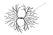
- the present inventors consider the mechanism by which protrusions are formed in the present invention as follows.
- the resin solution of the melted polyethylene resin and the molding solvent is extruded from the die, and at the same time, the crystallization of polyethylene is started.
- the crystallization speed is increased by contacting the cooling roll and quenching.
- a spherulite having a symmetric structure having a crystal nucleus is formed (FIG. 2).
- the heat transfer rate between the chill roll surface and the molten polyethylene resin is relatively low, the crystallization rate is low, resulting in spherulites having relatively small crystal nuclei.
- the heat transfer rate is high, the spherulite has a relatively large crystal nucleus.
- the molecular weight distribution (weight average molecular weight (Mw) / number average molecular weight (Mn)) of the polyethylene resin is preferably in the range of 5 to 200, more preferably 10 to 100.
- Mw / Mn is used as a measure of molecular weight distribution, that is, in the case of polyethylene consisting of a single substance, the larger this value, the wider the molecular weight distribution.
- the Mw / Mn of polyethylene composed of a single substance can be appropriately adjusted by multistage polymerization of polyethylene. Moreover, Mw / Mn of the mixture of polyethylene can be suitably adjusted by adjusting the molecular weight and mixing ratio of each component.
- the polyethylene porous film may be a single layer film or a layer structure composed of two or more layers having different molecular weights or average pore diameters.
- a layer structure composed of two or more layers it is preferable that the molecular weight and molecular weight distribution of at least one outermost polyethylene resin satisfy the above.
- the production method of the polyolefin porous membrane can be freely selected as long as it satisfies the above-mentioned various characteristics.
- phase separation is performed in terms of uniform micropores and cost. The method is preferred.
- phase separation method for example, polyethylene and a molding solvent are heated and melt-kneaded, and the obtained molten mixture is extruded from a die and cooled to form a gel-like molded product, and the obtained gel-like molding is obtained.
- examples include a method of obtaining a porous film by stretching the product in at least a uniaxial direction and removing the molding solvent.
- each of the polyethylene constituting the a layer and the b layer is melt-kneaded with a molding solvent, and the obtained molten mixture is supplied to each die from each extruder.
- the gel sheets constituting each component can be integrated and co-extruded, or the gel sheets constituting each layer can be superimposed and heat-sealed.
- the co-extrusion method is more preferable because it is easy to obtain a high interlayer adhesive strength, easily form communication holes between layers, easily maintain high permeability, and is excellent in productivity.
- the manufacturing method of the polyolefin porous membrane used for this invention includes the following steps (a) to (e).
- the molding solvent is not particularly limited as long as it can sufficiently dissolve polyethylene.
- Nonvolatile solvents such as liquid paraffin are preferred for obtaining.
- the dissolution by heating is performed by a method in which the polyethylene composition is completely dissolved and stirred and uniformly mixed in an extruder.
- the temperature varies depending on the polymer and solvent to be used when it is dissolved in an extruder or in a solvent while stirring, but it is preferably in the range of 140 to 250 ° C., for example.
- the concentration of the polyethylene resin is preferably 25 to 40 parts by weight, more preferably 28 to 35 parts by weight, with the total of the polyethylene resin and the molding solvent being 100 parts by weight.
- concentration of the polyethylene resin is within the above preferable range, a sufficient number of crystal nuclei for forming protrusions are formed, and a sufficient number of protrusions are formed.
- swell and neck-in are suppressed at the die outlet when extruding the polyethylene resin solution, and the moldability and self-supporting property of the extruded product are maintained.
- the method of melt kneading is not particularly limited, but is usually performed by uniformly kneading in an extruder. This method is suitable for preparing highly concentrated solutions of polyethylene.
- the melting temperature is preferably within the range of the melting point of polyethylene + 10 ° C. to + 100 ° C. In general, the melting temperature is preferably in the range of 160 to 230 ° C, more preferably in the range of 170 to 200 ° C.
- the melting point refers to a value obtained by differential scanning calorimetry (DSC) based on JIS K7121.
- the molding solvent may be added before the start of kneading, or may be added from the middle of the extruder during the kneading and further melt kneaded, but it is preferably added before the start of kneading and preliminarily formed into a solution. In melt kneading, it is preferable to add an antioxidant to prevent oxidation of polyethylene.
- (B) A process of extruding a polyethylene resin solution from a die and cooling with a cooling roll having a surface from which the forming solvent has been removed by a forming solvent removing means to form a gel-like molded product. Extruding the melt-kneaded polyethylene resin solution Extrude from the die directly from the machine or via another extruder. As the die, a sheet die having a rectangular base shape is usually used.
- a gel-like molded product is formed by bringing a polyethylene resin solution extruded from a die into contact with a rotating cooling roll set at a surface temperature of 20 ° C. to 40 ° C. with a refrigerant.
- the extruded polyethylene resin solution is preferably cooled to 25 ° C. or lower.
- the cooling rate in the temperature range where crystallization is substantially performed becomes important. For example, a polyethylene resin solution extruded at a cooling rate of 10 ° C./second or more in a temperature range where crystallization is substantially performed is cooled to obtain a gel-like molded product.
- a preferable cooling rate is 20 ° C./second or more, more preferably 30 ° C./second or more, and further preferably 50 ° C./second or more.
- the cooling rate can be estimated by simulating from the extrusion temperature of the gel-shaped molded product, the thermal conductivity of the gel-shaped molded product, the thickness of the gel-shaped molded product, the solvent for molding, the cooling roll, and the heat transfer coefficient of air.
- the present invention it is important to remove as much as possible the forming solvent adhering to the surface of the cooling roll in contact with the polyethylene resin solution extruded from the die. That is, as shown in FIG. 4, the polyethylene resin solution is cooled by being wound around a rotating cooling roll to become a gel-like molded product, but is formed on the surface of the cooling roll after being separated as a gel-like molded product. The solvent for use is attached, and it usually comes into contact with the polyethylene resin solution again as it is. However, if a large amount of the forming solvent adheres to the surface of the cooling roll, the cooling rate becomes slow due to the heat insulating effect, and it becomes difficult to form protrusions. Therefore, it is important to remove the forming solvent as much as possible before the cooling roll comes into contact with the polyethylene resin solution again.
- the method for removing the molding solvent that is, the method for removing the molding solvent from the cooling roll is not particularly limited, but the doctor blade is placed on the cooling roll so as to be parallel to the width direction of the gel-like molded article and passed through the doctor blade.
- a method is preferably employed in which the molding solvent is scraped off to the extent that the cooling roll surface is invisible until immediately after the gel-like molded product comes into contact.
- it can be removed by means such as blowing with compressed air, suction, or a combination of these methods.
- the method of scraping off using a doctor blade is preferable because it can be carried out relatively easily, and it is more preferable to use a plurality of doctor blades in order to improve the removal efficiency of the forming solvent.
- the material of the doctor blade is not particularly limited as long as it is resistant to the molding solvent, but is preferably made of resin or rubber rather than metal. This is because in the case of metal, the cooling roll may be scratched.
- the resin doctor blade include polyester, polyacetal, and polyethylene.
- the thickness of the polyethylene resin solution during extrusion is preferably 1500 ⁇ m or less, more preferably 1000 ⁇ m or less, and still more preferably 800 ⁇ m or less.
- the cooling rate on the surface on the side of the cooling roll is preferably not slow.
- this gel-like molded product is stretched to obtain a stretched molded product.
- Stretching is performed by heating the gel-like molded product and performing normal tenter method, roll method, or a combination of these methods at a predetermined magnification in two directions of MD and TD. Stretching may be simultaneous stretching in the machine direction and the width direction (simultaneous biaxial stretching) or sequential stretching. In the sequential stretching, the order of MD and TD is not limited, and at least one of MD and TD may be stretched in multiple stages.
- the stretching temperature is the melting point of the polyolefin composition + 10 ° C. or less.
- the draw ratio varies depending on the thickness of the original fabric, but is preferably 9 times or more, more preferably 16 to 400 times in terms of surface magnification.
- stretching at the same magnification of MD and TD such as 3 ⁇ 3, 5 ⁇ 5, and 7 ⁇ 7 is preferable.
- the surface magnification is in the above preferred range, stretching is sufficient and a highly elastic, high strength porous membrane can be obtained.
- a desired air resistance can be obtained by adjusting the stretching temperature.
- Cleaning solvents include hydrocarbons such as pentane, hexane and heptane, chlorinated hydrocarbons such as methylene chloride and carbon tetrachloride, fluorinated hydrocarbons such as ethane trifluoride, and ethers such as diethyl ether and dioxane. Volatile ones can be used.
- These washing solvents are appropriately selected according to the molding solvent used for dissolving polyethylene, and used alone or in combination.
- the cleaning method can be performed by a method of immersing and extracting in a cleaning solvent, a method of showering the cleaning solvent, a method of sucking the cleaning solvent from the opposite side of the stretched molded product, or a method of a combination thereof. Washing as described above is performed until the residual solvent in the stretched molded product is less than 1% by weight. Thereafter, the cleaning solvent is dried.
- the cleaning solvent can be dried by heat drying, air drying, or the like.
- Step of heat-treating porous molded product to obtain polyethylene porous membrane The porous molded product obtained by drying is further subjected to heat treatment to obtain a polyethylene porous membrane.
- the heat treatment temperature is preferably 90 to 150 ° C.
- the resulting polyolefin porous membrane is sufficiently secured to reduce the heat shrinkage rate and the air resistance.
- the residence time of the heat treatment step is not particularly limited, but is usually 1 second to 10 minutes, preferably 3 seconds to 2 minutes or less.
- any of a tenter method, a roll method, a rolling method, and a free method can be adopted.
- the heat treatment step it is preferable to contract in at least one direction of MD and TD while fixing in both directions of MD (machine direction) and TD (width direction). If the MD and TD are fixed in both directions and the MD and TD are not contracted in at least one direction, the heat shrinkage reduction is deteriorated.
- the contraction rate for contracting in at least one direction of MD and TD is 0.01 to 50%, preferably 3 to 20%. When the shrinkage rate is within the above preferable range, the thermal shrinkage rate at 105 ° C. and 8 hours is improved, and the air resistance is maintained.
- a function providing step such as a corona treatment step or a hydrophilization step may be provided as necessary.
- the modified porous layer is preferably laminated on the side of the polyolefin porous membrane having the protrusions.
- a modified porous layer is provided on both surfaces of a polyolefin porous membrane, the modified porous layer on the side to which parallel stress is more strongly applied by the contact of a roll or a bar in a subsequent process such as a slit process or a transport process is made of polyethylene porous It is preferable to laminate on the surface side having the projection of the membrane because the effect of the present invention is exhibited.
- the modified porous layer in the present invention has at least a fluorine resin and inorganic particles.
- the content of the inorganic particles with respect to the total of the fluororesin and the inorganic particles in the modified porous layer is 40% by weight or more and less than 80% by weight. By making it into this range, electrode adhesion, heat resistance, and electrolyte solution permeability can be obtained in a well-balanced manner.
- the fluororesin used in the present invention is not particularly limited as long as it improves electrode adhesion, heat resistance, and electrolyte permeability, but from the viewpoint of heat resistance and electrode adhesion, vinylidene fluoride homopolymer, fluoride It is preferable to use one or more selected from the group consisting of vinylidene / fluorinated olefin copolymer, vinyl fluoride homopolymer, and vinyl fluoride / fluorinated olefin copolymer. Particularly preferred are polyvinylidene fluoride resins. These polymers have electrode adhesion, high affinity with non-aqueous electrolytes, appropriate heat resistance, and high chemical and physical stability against non-aqueous electrolytes. Even when used, the affinity with the electrolyte can be sufficiently maintained.
- a commercially available resin can be used as the polyvinylidene fluoride resin.
- Inorganic particles include calcium carbonate, calcium phosphate, amorphous silica, crystalline glass filler, kaolin, talc, titanium dioxide, alumina, silica-alumina composite oxide particles, barium sulfate, calcium fluoride, lithium fluoride, zeolite , Molybdenum sulfide, mica and the like.
- the average particle size of the inorganic particles is preferably 1.5 to 50 times, more preferably 2.0 to 20 times the average pore size of the polyolefin porous membrane.
- the average particle diameter of the particles is within the above-mentioned preferable range, the air resistance is maintained without blocking the pores of the polyolefin porous membrane in a state where the heat-resistant resin and the particles are mixed, and further, in the battery assembly process, the particles Prevents falling off and causing serious battery defects.
- the shape of the particle includes a true sphere shape, a substantially spherical shape, a plate shape, and a needle shape, but is not particularly limited.
- the content of the inorganic particles with respect to the total of the fluororesin and the inorganic particles of the modified porous layer is preferably 40% by weight or more and less than 80% by weight.
- the upper limit of the content of these inorganic particles is more preferably 75% by weight, still more preferably 70% by weight.
- the lower limit is preferably 40% by weight, more preferably 45% by weight.
- the film thickness of the modified porous layer is preferably 1 to 5 ⁇ m, more preferably 1 to 4 ⁇ m, and most preferably 1 to 3 ⁇ m.
- the film thickness is 1 ⁇ m or more, adhesion to the electrode is ensured, and the polyolefin microporous film is prevented from being melted and shrunk at the melting point or more, and the film breaking strength and insulation can be secured.
- it is 5 ⁇ m or less, by optimizing the proportion of the polyolefin microporous film, a sufficient pore blocking function can be obtained and abnormal reactions can be suppressed. Further, the volume of winding can be suppressed, which is suitable for increasing the capacity of the battery that will be advanced in the future. Furthermore, curling is prevented from increasing, leading to an improvement in productivity in the battery assembly process.
- the porosity of the modified porous layer is preferably 30 to 90%, more preferably 40 to 70%.
- the porosity is 30% or more, an increase in the electrical resistance of the film can be prevented and a large current can flow.
- the porosity is 90% or less, the film strength can be maintained.
- the desired porosity can be obtained by appropriately adjusting the concentration of inorganic particles, the binder concentration, and the like.
- the porosity of the modified porous layer is within the above-mentioned preferable range, the laminated porous film obtained by laminating the modified porous layer has a low electrical resistance, a large current flows easily, and the film strength is maintained. Is done.
- the upper limit of the total film thickness of the battery separator obtained by laminating the modified porous layer is preferably 30 ⁇ m, more preferably 25 ⁇ m.
- the lower limit is preferably 5 ⁇ m, more preferably 7 ⁇ m. Sufficient mechanical strength and insulation can be ensured by setting the total film thickness of the battery separator to the preferred lower limit value or more. Moreover, since it can ensure the electrode area which can be filled in a container by setting it as the said preferable upper limit or less, the fall of a capacity
- Lamination method of modified porous layer A lamination method of the modified porous layer will be described.
- a fluororesin solution that is soluble in a fluororesin and is dissolved in a solvent miscible with water, and a varnish mainly composed of particles are laminated on the polyolefin microporous film obtained above using a coating method, Subsequently, the modified porous layer is obtained by placing in a specific humidity environment, phase-separating a solvent miscible with the fluorine-based resin and water, and adding the solution to a water bath (coagulation bath) to solidify the fluorine-based resin.
- coagulation bath coagulation bath
- Examples of the method for applying the varnish include a dip coating method, a reverse roll coating method, a gravure coating method, a kiss coating method, a roll brush method, a spray coating method, an air knife coating method, a Mayer bar coating method, and a pipe.
- Examples include a doctor method, a blade coating method, and a die coating method, and these methods can be performed alone or in combination.
- the fluororesin component coagulates in a three-dimensional network.
- the immersion time in the coagulation bath is preferably 3 seconds or more. If it is less than 3 seconds, the resin component may not be sufficiently solidified. The upper limit is not limited, but 10 seconds is sufficient.
- pure water is used by immersing the unwashed microporous membrane in an aqueous solution containing 1 to 20% by weight, more preferably 5 to 15% by weight of a good solvent for the fluororesin constituting the modified porous layer.
- the final battery separator can be obtained through a washing step and a drying step using hot air of 100 ° C. or lower.
- the battery separator of the present invention is desirably stored in a dry state. However, when it is difficult to store in a completely dry state, it is preferable to perform a vacuum drying treatment at 100 ° C. or lower immediately before use.
- the battery separator of the present invention is used for batteries such as nickel-hydrogen batteries, nickel-cadmium batteries, nickel-zinc batteries, silver-zinc batteries, lithium ion secondary batteries, lithium polymer secondary batteries and the like. Although it can be used as a separator, it is particularly preferably used as a separator for a lithium ion secondary battery.
- the air resistance of the battery separator is one of the most important characteristics, and is preferably 50 to 600 sec / 100 cc Air, more preferably 100 to 500 sec / 100 cc Air, and still more preferably 100 to 400 sec / 100 cc Air.
- the desired air resistance can be obtained by adjusting the porosity of the modified porous layer and adjusting the degree of penetration of the binder into the polyolefin porous membrane.
- the air permeability resistance of the battery separator is within the above preferable range, sufficient insulation is obtained, and foreign matter clogging, short circuit and film breakage are prevented. Further, by suppressing the film resistance, charge / discharge characteristics and life characteristics within a practically usable range can be obtained.
- the measured value in an Example is a value measured with the following method.
- Electrode adhesiveness The negative electrode and the battery separator were each cut into a size of 2 cm ⁇ 5 cm, the active material surface of the negative electrode and the modified porous layer surface of the battery separator were combined, and the bonding surface temperature was maintained at 50 ° C. Pressed for 3 minutes under pressure. Thereafter, the negative electrode and the battery separator were peeled off, and the peeled surface was observed and judged according to the following criteria.
- a coat electrode A100 1.6 mAh / cm 2 ) manufactured by Piotrec Co., Ltd. was used as a negative electrode.
- Negative electrode active material adheres to modified porous layer of battery separator by 70% or more in area ratio
- Negative electrode active material adheres to modified porous layer of battery separator by area ratio of 60% or more and less than 70%
- Adhesion failure The active material of the negative electrode adheres to the modified porous layer of the battery separator in an area ratio of less than 60%.
- protrusions The number and size of protrusions were measured after stabilizing the light source using a confocal microscope (HD100 manufactured by Lasertec) installed on a base isolation table.
- a confocal microscope HD100 manufactured by Lasertec
- a 1 cm ⁇ 1 cm square frame was drawn with an ultrafine oil pen on the surface of the polyethylene porous membrane obtained in Examples and Comparative Examples that was in contact with the cooling roll during film formation.
- the surface on which the square frame was drawn was placed on the sample stage, and was fixed to the sample stage using an electrostatic contact apparatus attached to the confocal microscope.
- an objective lens with a magnification of 5 times a ring-shaped trace derived from a polyethylene spherulite as shown in FIG.
- a TOD 3 is displayed on a monitor as a two-dimensional image (referred to as a REAL screen in this apparatus), and the ring-shaped trace is displayed.
- the position of the sample stage was adjusted so that the darkest part of was positioned almost at the center of the monitor screen.
- the object of the projection height measurement was such that the major axis of the ring-shaped trace derived from the polyethylene spherulites was 0.2 mm or more.
- the cursor was placed on both ends of the ring in the major axis direction in the two-dimensional image, and the length was read.
- FIG. 1 schematically shows the evaluation method.
- 1 is a laminated sample
- 2 is a polyolefin porous membrane
- 3 is a modified porous layer
- 4 is a double-sided pressure-sensitive adhesive tape
- the aluminum plate 5 and the aluminum plate 5 ′ sandwiching the sample are attached to a tensile tester (Autograph AGS-J load cell capacity 1 kN, manufactured by Shimadzu Corporation), and the aluminum plate 5 and the aluminum plate 5 ′ are opposite to each other in parallel.
- the film was pulled in the direction at a pulling speed of 10 mm / min, and the strength when the modified porous layer was peeled was measured. This measurement was performed for any three points with an interval of 30 cm or more in the longitudinal direction, and the average value was taken as the 0 ° peel strength of the modified porous layer.
- the peeling defects were counted and evaluated according to the following criteria.
- the evaluation area was 100 mm wide ⁇ 500 m long. (When the width was less than 100 mm, the length was adjusted so that the same evaluation area was obtained.)
- UHMWPE ultrahigh molecular weight polyethylene
- HDPE high density polyethylene
- a polyethylene composition (melting point: 135 ° C.) obtained by adding 0.375 parts by weight of an antioxidant was obtained.
- 30 parts by weight of this polyethylene composition was put into a twin screw extruder. 70 parts by weight of liquid paraffin was supplied from the side feeder of this twin screw extruder, melt kneaded, and a polyethylene resin solution was prepared in the extruder.
- this gel-like molded product was simultaneously biaxially stretched 5 ⁇ 5 times while adjusting the temperature so as to obtain a desired air permeability resistance to obtain a stretched molded product.
- the obtained stretched molded product was washed with methylene chloride to extract and remove the remaining liquid paraffin, and dried to obtain a porous molded product.
- the porous molded product is held in the tenter, reduced in width by 10% only in the TD (width direction) direction, heat treated at 90 ° C. for 3 seconds, thickness 9 ⁇ m, porosity 45%, average pore diameter 0.15 ⁇ m,
- a polyethylene porous membrane having an air permeability resistance of 240 sec / 100 cc Air was obtained.
- PVdF / HFP 92/8 (weight ratio)
- PVDF copolymer having a weight average molecular weight of 1,000,000
- the fluorine resin, alumina particles having an average particle diameter of 0.5 ⁇ m, and N-methyl-2-pyrrolidone were blended in a weight ratio of 5:12:83, respectively, and the resin component was dissolved, and then zirconium oxide beads (Toray ( Together with “Traceram” (registered trademark) beads manufactured by Co., Ltd., 0.5 mm in diameter), they were placed in a polypropylene container and dispersed with a paint shaker (manufactured by Toyo Seiki Seisakusho Co., Ltd.) for 6 hours. Subsequently, it filtered with the filter of 5 micrometers of filtration limits, and prepared the varnish (a). The weight ratio of the fluororesin (solid content) to the particles was 29:71. In addition, the varnish was hermetically stored so as not to touch outside air as much as possible until coating.
- the varnish (a) was applied to the surface of the polyolefin microporous membrane in contact with the cooling roll by the Mayer bar coating method, and subsequently passed through a humidity control zone at a temperature of 25 ° C. and an absolute humidity of 12 g / m 3 for 5 seconds. . Next, it was allowed to enter an aqueous solution (coagulation tank) containing 5% by weight of N-methyl-2-pyrrolidone, washed with pure water, and then dried by passing through a hot air drying oven at 70 ° C. to a final thickness of 11 ⁇ m. A battery separator was obtained.
- aqueous solution coagulation tank
- Example 2 Example 1 except that the blending ratio of ultra high molecular weight polyethylene (UHMWPE) having a weight average molecular weight of 2 million and high density polyethylene (HDPE) having a weight average molecular weight of 350,000 was changed to 10:90 (weight% ratio). Thus, a battery separator was obtained.
- UHMWPE ultra high molecular weight polyethylene
- HDPE high density polyethylene
- Example 3 Example 1 except that the blending ratio of ultra high molecular weight polyethylene (UHMWPE) with a weight average molecular weight of 2 million and high density polyethylene (HDPE) with a weight average molecular weight of 350,000 was changed to 20:80 (weight% ratio). Thus, a battery separator was obtained.
- UHMWPE ultra high molecular weight polyethylene
- HDPE high density polyethylene
- Example 4 Example 1 except that the blending ratio of ultra high molecular weight polyethylene (UHMWPE) with a weight average molecular weight of 2 million and high density polyethylene (HDPE) with a weight average molecular weight of 350,000 was changed to 30:70 (weight% ratio). Thus, a battery separator was obtained.
- UHMWPE ultra high molecular weight polyethylene
- HDPE high density polyethylene
- Example 5 Example 1 except that the blending ratio of ultra high molecular weight polyethylene (UHMWPE) having a weight average molecular weight of 2 million and high density polyethylene (HDPE) having a weight average molecular weight of 350,000 was changed to 40:60 (weight% ratio). Thus, a battery separator was obtained.
- UHMWPE ultra high molecular weight polyethylene
- HDPE high density polyethylene
- Example 6 A battery separator was obtained in the same manner as in Example 1 except that two polyester doctor blades were applied to the cooling roll at an interval of 20 mm.
- Example 7 A battery separator was obtained in the same manner as in Example 1 except that three polyester doctor blades were each applied to the cooling roll at an interval of 20 mm.
- Example 8 Example 1 was used except that a varnish (b) containing a fluorine resin, alumina particles having an average particle diameter of 0.5 ⁇ m, and N-methyl-2-pyrrolidone in a weight ratio of 10: 7: 83 was used. A battery separator was obtained. The weight ratio of the fluororesin (solid content) to the particles was 59:41.
- Example 9 Example 1 was used except that a varnish (c) containing a fluorine resin, alumina particles having an average particle diameter of 0.5 ⁇ m, and N-methyl-2-pyrrolidone in a weight ratio of 4:13:83 was used. A battery separator was obtained. The weight ratio of the fluororesin (solid content) to the particles was 24:76.
- Example 10 A battery separator was obtained in the same manner as in Example 1 except that varnish (d) replaced with polyvinylidene fluoride (weight average molecular weight: 630,000) was used as the fluorine resin.
- Example 11 A battery separator was obtained in the same manner as in Example 1 except that varnish (e) replaced with polyvinylidene fluoride (weight average molecular weight: 1,000,000) was used as the fluorine-based resin.
- Example 12 The Meyer bar coating method was changed to the dip coating method, and the polyolefin microporous membrane was laminated on both surfaces with a thickness of 2 ⁇ m after drying to obtain a battery separator having a final thickness of 13 ⁇ m.
- Example 13 A battery separator was obtained in the same manner as in Example 1 except that the internal cooling water temperature of the cooling roll was maintained at 35 ° C.
- Example 14 A battery separator having a final thickness of 22 ⁇ m was obtained in the same manner as in Example 1 except that the extrusion amount of the polyethylene resin solution was adjusted to obtain a polyethylene porous membrane having a thickness of 20 ⁇ m.
- Example 15 A battery separator was obtained in the same manner as in Example 1 except that 26 parts by weight of the polyethylene composition was charged into a twin screw extruder, 74 parts by weight of liquid paraffin was supplied from the side feeder of the twin screw extruder, and melt kneaded. It was.
- Example 16 A battery separator was obtained in the same manner as in Example 1 except that 35 parts by weight of the polyethylene composition was charged into a twin screw extruder, 65 parts by weight of liquid paraffin was supplied from the side feeder of the twin screw extruder, and melt kneaded. It was.
- Example 17 A battery separator was obtained in the same manner as in Example 1 except that the coating liquid (f) in which the alumina particles were replaced with titanium oxide particles (average particle size 0.38 ⁇ m) was used.
- Example 18 A battery separator was obtained in the same manner as in Example 1 except that the coating liquid (g) in which the alumina particles were replaced with plate-like boehmite fine particles (average particle diameter: 1.0 ⁇ m) was used.
- Comparative Example 1 The polyethylene resin solution extruded from the die was cooled with a cooling roll, and when the gel-like molded product was obtained, the doctor blade was not used and the liquid paraffin adhering to the cooling roll was not scraped off. Similarly, a battery separator was obtained.
- HDPE high density polyethylene having a weight average molecular weight of 350,000
- Comparative Example 3 A battery separator was obtained in the same manner as in Example 1 except that the internal cooling water temperature of the cooling roll was kept at 0 ° C. and the doctor blade was not used.
- Comparative Example 4 Instead of cooling the polyethylene resin solution extruded from the die with a cooling roll, a battery separator was obtained in the same manner as in Example 1 except that the polyethylene resin solution was immersed in water kept at 25 ° C. for 1 minute.
- Comparative Example 5 50 parts by weight of the polyethylene composition used in Example 1 was put into a twin screw extruder, 50 parts by weight of liquid paraffin was supplied from the side feeder of the twin screw extruder, melted and kneaded, and the polyethylene resin was fed into the extruder. Although a solution was prepared and extrusion from a die was attempted, it could not be extruded into a uniform film.
- Comparative Example 6 A battery separator was obtained in the same manner as in Example 1 except that the internal cooling water temperature of the cooling roll was kept at 50 ° C.
- Comparative Example 7 Example 1 was used except that a varnish (h) containing a fluorine resin, alumina particles having an average particle diameter of 0.5 ⁇ m, and N-methyl-2-pyrrolidone in a weight ratio of 2:15:83 was used. A battery separator was obtained. The weight ratio of the fluororesin (solid content) to the particles was 12:88.
- Polyamideimide resin solution alumina particles with an average particle size of 0.5 ⁇ m, and N-methyl-2-pyrrolidone were blended in a weight ratio of 34:12:54, respectively, and zirconium oxide beads (“Traceram” manufactured by Toray Industries, Inc. (registered) (Trademark) beads, 0.5 mm in diameter) were placed in a polypropylene container and dispersed for 6 hours with a paint shaker (Toyo Seiki Seisakusho). Subsequently, it filtered with the filter of 5 micrometers of filtration limits, and obtained coating liquid (i).
- zirconium oxide beads (“Traceram” manufactured by Toray Industries, Inc. (registered) (Trademark) beads, 0.5 mm in diameter) were placed in a polypropylene container and dispersed for 6 hours with a paint shaker (Toyo Seiki Seisakusho). Subsequently, it filtered with the filter of 5 micrometers of filtration limits, and obtained coating liquid (i).
- the coating liquid (i) was applied to the polyolefin porous membrane obtained in the same manner as in Example 1 in the same manner as in Example 1 to obtain a battery separator having a final thickness of 11 ⁇ m.
- the weight ratio of the polyamideimide resin (solid content) to the particles was 26:74.
- Example 1 was used except that a varnish (j) containing a fluorine resin, alumina particles having an average particle diameter of 0.5 ⁇ m, and N-methyl-2-pyrrolidone in a weight ratio of 11: 6: 83 was used. A battery separator was obtained. The weight ratio of the fluororesin (solid content) to the particles was 65:35. The heat resistance was inferior.
- Tables 1 and 2 show the characteristics of the battery separators obtained in Examples 1 to 18 and Comparative Examples 1 to 9.
Landscapes
- Chemical & Material Sciences (AREA)
- Engineering & Computer Science (AREA)
- Chemical Kinetics & Catalysis (AREA)
- Electrochemistry (AREA)
- General Chemical & Material Sciences (AREA)
- Mechanical Engineering (AREA)
- Materials Engineering (AREA)
- Inorganic Chemistry (AREA)
- Thermal Sciences (AREA)
- Physics & Mathematics (AREA)
- Manufacturing & Machinery (AREA)
- Composite Materials (AREA)
- Cell Separators (AREA)
- Laminated Bodies (AREA)
- Manufacture Of Porous Articles, And Recovery And Treatment Of Waste Products (AREA)
Abstract
Description
本明細書でいう、ポリオレフィン多孔質膜と改質多孔層との剥離強度とは、以下の方法により測定される値である(以下、0°剥離強度という場合がある。)。
図1に、引張試験機(図示しない)によって引っ張った状態のポリオレフィン多孔質膜と改質多孔層の積層試料の側面の様子を模式的に示している。1が積層試料、2がポリオレフィン多孔質膜、3が改質多孔層、4が両面粘着テープ、5及び5'がアルミニウム板であり、図中の矢印が引張方向である。大きさ50mm×25mm、厚さ0.5mmのアルミニウム板(5)に同じ大きさの両面粘着テープ(4)を貼り付け、その上に幅50mm×長さ100mmに切り出した試料(1)(積層多孔質膜)のポリオレフィン多孔質膜(2)の面を前記アルミニウム板(5)の25mm長さの片辺の端から40mmが重なるように貼り付け、はみ出た部分を切り取る。次いで、長さ100mm、幅15mm、厚さ0.5mmのアルミニウム板(5')の片面に両面粘着テープを貼り付け、前記アルミニウム板(5)の25mm長さの試料側の片辺の端から20mmが重なるように貼り付ける。その後、アルミニウム板(5)とアルミニウム板(5')を平行に反対方向に引張試験機を用いて、引張速度10mm/minで引っ張り、改質多孔層が剥離したときの強度を測定する。本評価方法で剥離強度が130N/15mm以上であれば、ポリオレフィン多孔質膜の厚さが10μm以下のような場合であっても、積層された改質多孔層が搬送中、あるいは加工中に剥がれ現象はほとんど生じない。
剥離強度の測定法として従来から用いられているT型剥離強度または180°での剥離強度は、ポリエチレン製多孔膜から塗布層をポリエチレン製多孔膜表面に対して垂直または垂直から斜め後方に引きはがす時の剥離力である。本評価方法によれば、これら従来の評価方法に比べてスリット工程や電池組み立て工程における擦れ耐性をより実際に即して評価することができる。
(1)ポリオレフィンからなる5μm≦W≦50μm(Wは突起の大きさ)および0.5μm≦H(Hは突起の高さ)をみたす突起が、3個/cm2以上、200個/cm2以下で少なくとも片面に不規則に点在するポリオレフィン多孔質膜と該ポリオレフィン多孔質膜の前記突起を有する面に積層されたフッ素系樹脂と無機粒子を含む改質多孔層とを少なくとも有し、前記改質多孔層のフッ素系樹脂と無機粒子の合計に対する無機粒子の含有量が40重量%以上、80重量%未満である電池用セパレータ。
(2)前記ポリオレフィン多孔質膜の厚さが25μm以下である(1)に記載の電池用セパレータ。
(3)前記無機粒子が炭酸カルシウム、アルミナ、チタニア、硫酸バリウム及びベーマイトからなる群から選ばれる少なくとも1種を含む(1)または(2)に記載の電池用セパレータ。
(4)リチウムイオン二次電池用セパレータとして用いる(1)~(3)のいずれかに記載の電池用セパレータ。
(5)(a)ポリエチレン樹脂に成形用溶剤を添加した後、溶融混練し、ポリエチレン樹脂溶液を調製する工程
(b)前記ポリエチレン樹脂溶液をダイより押出し、成形用溶剤が除去された表面を有する冷却ロールにて冷却し、ゲル状成形物を形成する工程
(c)前記ゲル状成形物を機械方向および幅方向に延伸し、延伸成形物を得る工程
(d)延伸成形物から前記成形用溶剤を抽出除去し、乾燥し、多孔質成形物を得る工程
(e)多孔質成形物を熱処理し、ポリオレフィン多孔質膜を得る工程
(f)前記冷却ロールが接していた面に、フッ素系樹脂と無機粒子、及び前記フッ素系樹脂を溶解または分散しうる溶媒を含む塗布液を用いて積層膜を形成し、乾燥する工程を含む(1)~(4)のいずれかに記載の電池用セパレータの製造方法。
(6)前記(b)工程における成形用溶剤の除去手段がドクターブレードである(5)に記載の電池用セパレータの製造方法。
なお、本発明における突起の大きさ及び高さは、後述する測定方法で測定した値をいう。
まず、本発明のポリオレフィン多孔質膜について説明する。
本発明のポリオレフィン多孔質膜の厚さは25μm以下が好ましく、上限は20μmが好ましく、より好ましくは16μmである。下限は7μmが好ましく、より好ましくは9μmである。ポリオレフィン多孔質膜の厚さが上記好ましい範囲であると、実用的な膜強度と孔閉塞機能を保有させることが出来き、電池ケースの単位容積当たりの面積が制約されず、今後、進むであろう電池の高容量化には適する。
ポリエチレンは、超高分子量ポリエチレン、高密度ポリエチレン、中密度ポリエチレン及び低密度ポリエチレンなどが挙げられる。また重合触媒にも特に制限はなく、チーグラー・ナッタ系触媒やフィリップス系触媒やメタロセン系触媒などが挙げられる。これらのポリエチレンはエチレンの単独重合体のみならず、他のα‐オレフィンを少量含有する共重合体であってもよい。エチレン以外のα‐オレフィンとしてはプロピレン、1‐ブテン、1‐ペンテン、1‐ヘキセン、4‐メチル‐1‐ペンテン、1‐オクテン、(メタ)アクリル酸、(メタ)アクリル酸のエステル、スチレン等が好適である。
ポリオレフィン多孔質膜は、上記の各種特徴を満足する範囲内ならば、目的に応じた製造方法を自由に選択することができる。多孔質膜の製造方法としては、発泡法、相分離法、溶解再結晶法、延伸開孔法、粉末焼結法などがあり、これらの中では微細孔の均一化、コストの点で相分離法が好ましい。
本発明に用いるポリオレフィン多孔質膜の製造方法は以下の(a)~(e)の工程を含むものである。
(a)ポリオレフィン樹脂に成形用溶剤を添加した後、溶融混練し、ポリオレフィン樹脂溶液を調製する工程
(b)前記ポリオレフィン樹脂溶液をダイより押出し、成形用溶剤除去手段により、成形用溶剤を除去した表面を有する冷却ロールにて冷却し、ゲル状成形物を形成する工程
(c)前記ゲル状成形物を機械方向(MD)および幅方向(TD)に延伸し、延伸成形物を得る工程
(d)前記延伸成形物から前記成形用溶剤を除去し、乾燥し、多孔質成形物を得る工程
(e)前記多孔質成形物を熱処理し、ポリオレフィン多孔質膜を得る工程。
更に(a)~(e)の工程の後、必要に応じてコロナ処理工程等を設けてもよい。
(a)ポリエチレン樹脂に成形用溶剤を添加した後、溶融混練し、ポリエチレン樹脂溶液を調製する工程
成形用溶剤としては、ポリエチレンを十分に溶解できるものであれば特に限定されない。例えば、ノナン、デカン、ウンデカン、ドデカン、流動パラフィンなどの脂肪族または環式の炭化水素、あるいは沸点がこれらに対応する鉱油留分などがあげられるが、溶剤含有量が安定なゲル状成形物を得るためには流動パラフィンのような不揮発性の溶剤が好ましい。加熱溶解は、ポリエチレン組成物が完全に溶解する温度で攪拌または押出機中で均一混合して溶解する方法で行う。その温度は、押出機中又は溶媒中で攪拌しながら溶解する場合は使用する重合体及び溶媒により異なるが、例えば140~250℃の範囲が好ましい。
溶融混練したポリエチレン樹脂溶液を押出機から直接的に又は別の押出機を介してダイから押し出す。ダイとしては、通常は長方形の口金形状をしたシート用ダイを用いる。
次に、このゲル状成形物を延伸し、延伸成形物とする。延伸は、ゲル状成形物を加熱し、通常のテンター法、ロール法、もしくはこれらの方法の組み合わせによってMD及びTDの二方向に所定の倍率で行う。延伸は機械方向と幅方向の同時延伸(同時二軸延伸)または逐次延伸のいずれでもよい。逐次延伸はMDとTDの順序は問わず、MD及びTDの少なくとも一方を多段で延伸してもよい。延伸温度はポリオレフィン組成物の融点+10℃以下である。また延伸倍率は、原反の厚さによって異なるが面倍率で9倍以上が好ましく、より好ましくは16~400倍である。同時二軸延伸であれば3×3、5×5及び7×7などのMD及びTD同倍率での延伸が好ましい。面倍率が上記好ましい範囲であると、延伸が十分であり高弾性、高強度の多孔質膜が得られる。また延伸温度を調整することによって所望の透気抵抗度を得ることができる。
次に、延伸された延伸成形物を洗浄溶剤で処理して残留する成形用溶剤を除去し、多孔質成形物を得る。洗浄溶剤としては、ペンタン、ヘキサン、ヘプタンなどの炭化水素、塩化メチレン、四塩化炭素などの塩素化炭化水素、三フッ化エタンなどのフッ化炭化水素、ジエチルエーテル、ジオキサンなどのエーテル類などの易揮発性のものを用いることができる。これらの洗浄溶剤はポリエチレンの溶解に用いた成形用溶剤に応じて適宜選択し、単独もしくは混合して用いる。洗浄方法は、洗浄溶剤に浸漬し抽出する方法、洗浄溶剤をシャワーする方法、洗浄溶剤を延伸成形物の反対側から吸引する方法、またはこれらの組合せによる方法などにより行うことができる。上述のような洗浄は、延伸成形物中の残留溶剤が1重量%未満になるまで行う。その後、洗浄溶剤を乾燥するが、洗浄溶剤の乾燥方法は加熱乾燥、風乾などの方法で行うことができる。
乾燥して得られた多孔質成形物は、さらに熱処理を行い、ポリエチレン多孔質膜を得る。熱処理温度は90~150℃にて行うのが好ましい。熱処理温度が上記好ましい範囲であると、得られたポリオレフィン多孔質膜の熱収縮率低減および透気抵抗度が十分確保される。かかる熱処理工程の滞留時間は、特に限定されることはないが、通常は1秒以上10分以下、好ましくは3秒から2分以下で行われる。熱処理は、テンター方式、ロール方式、圧延方式、フリー方式のいずれも採用できる。
なお、(a)~(e)の工程の後、必要に応じてコロナ処理工程や親水化工程等の機能付与工程を設けてもよい。
次に、本発明に用いる改質多孔層について説明する。
改質多孔層はポリオレフィン多孔質膜の突起を有する面側に積層するのが好ましい形態である。ポリオレフィン多孔質膜の両面に改質多孔層を設ける場合は、スリット工程や搬送工程などの後工程において、ロールやバーなどの接触によって平行な応力がより強くかかる側の改質多孔層をポリエチレン多孔質膜の突起を有する面側に積層するのが、本発明による効果が発揮されるため好ましい。
改質多孔層の積層方法について説明する。フッ素系樹脂に対して可溶で且つ水と混和する溶剤で溶解したフッ素系樹脂溶液と、粒子を主成分とするワニスを前述で得られたポリオレフィン微多孔膜に塗布法を用いて積層し、続いて特定の湿度環境下に置き、フッ素系樹脂と水と混和する溶剤を相分離させ、さらに水浴(凝固浴)に投入してフッ素系樹脂を凝固させることによって改質多孔層は得られる。
本発明の電池用セパレータは、乾燥状態で保存することが望ましいが、絶乾状態での保存が困難な場合は、使用の直前に100℃以下の減圧乾燥処理を行うことが好ましい。
また、本発明の電池用セパレータは、ニッケル-水素電池、ニッケル‐カドミウム電池、ニッケル‐亜鉛電池、銀-亜鉛電池、リチウムイオン二次電池、リチウムポリマー二次電池等の二次電池などの電池用セパレータとして用いることができるが、特にリチウムイオン二次電池のセパレータとして用いるのが好ましい。
負極および電池用セパレータをそれぞれ2cm×5cmの大きさに切り出し、負極の活物質面と電池用セパレータの改質多孔層面を合わせ、貼り合わせ面の温度を50℃に保持しながら2MPaの圧力で3分間プレスした。その後、負極と電池用セパレータを剥がし、剥離面を観察して以下の基準より判定した。尚、負極電極としてパイオトレック(株)製、コート電極A100(1.6mAh/cm2)を用いた。
極めて良好:負極の活物質が電池用セパレータの改質多孔層に面積比で70%以上付着
良好:負極の活物質が電池用セパレータの改質多孔層に面積比で60%以上、70%未満付着
不良:負極の活物質が電池用セパレータの改質多孔層に面積比で60%未満付着
突起の数と大きさは免震台上に設置したコンフォーカル(共焦点)顕微鏡(Lasertec社製 HD100)を用いて、光源を安定化させた後に測定した。
(手順)
(1)実施例および比較例で得られたポリエチレン多孔質膜を製膜時に冷却ロールに接していた面に1cm×1cmの正方形の枠を極細油性ペンで描いた。
(2)上記正方形の枠を描いた面を上にしてサンプルステージに載せ、コンフォーカル顕微鏡付属の静電気密着装置を用いてサンプルステージに密着固定させた。
(3)倍率5倍の対物レンズを用いて、図3のようなポリエチレンの球晶に由来するリング状痕をモニターに二次元画像(本装置ではREAL画面と称す)として表示させ、リング状痕の最も色の濃い部分がモニター画面のほぼ中央に位置するようにサンプルステージ位置を調整した。リング状痕が2つ連なっている場合はその接点に合わせた。突起高さ測定の対象は前記ポリエチレンの球晶に由来するリング状痕の長径が0.2mm以上のものとした。リング状痕の長径は前記二次元画像にて長径方向にリングの両端にカーソルを合わせ、その長さを読み取った。
(4)対物レンズを20倍レンズに替え、モニター画面の中央部にフォーカスを合わせて(本装置ではモニター画面の中央部が最も明るく表示されようにする)、この高さ位置を基準高さとした(本装置ではREF SETと称す)。
(5)高さ方向の測定範囲は前記基準高さを0μmとして上下15μmに設定した。また、スキャン時間120秒、STEP移動距離0.1μm/Stepとし、三次元データを取り込んだ。
(6)三次元データ取り込み後、データ処理用画像(本装置ではZ画像と称す)を表示させ、スムージング処理を行った(スムージング条件:フィルタサイズ3x3、マトリックスタイプ SMOOTH3-0、回数1回)。また、必要に応じて水平補正画面にて水平補正を行った。
(7)データ処理用画像にて最も高い突起を通る位置(最も明るい部分)に水平方向にカーソルを置き、前記カーソルに対応した断面プロファイルを、断面プロファイル画像に表示させた。
(8)断面プロファイル画像にて垂直方向に2本のカーソルを突起の両袖の変曲点に合わせ両カーソル間の距離を突起の大きさとした。
(9)断面プロファイル画像にて水平方向に2本のカーソルを突起の頂点と突起の両袖の変曲点に合わせ(突起の両袖の変曲点の高さが異なる場合は低い方)両カーソル間の距離を突起の高さとした。
(10)前記操作を前記1cm×1cmの正方形の枠内で繰り返し、大きさ5μm以上、50μm以下、高さ0.5μm以上、3.0μm以下の突起の数を数え1cm2当たりの突起数を求め、さらにその突起の高さ平均値を求めた。
図1に、評価方法を模式的に示す。1が積層試料、2がポリオレフィン多孔質膜、3が改質多孔層、4が両面粘着テープ、5及び5'がアルミニウム板であり、図中の矢印が引張方向である。大きさ50mm×25mm、厚さ0.5mmのアルミニウム板5に同じ大きさの両面粘着テープ(ニチバン(株)製NW‐K50)4を貼り付けた。その上に幅50mm×長さ100mmに切り出した試料1(積層多孔質膜)のポリオレフィン多孔質膜2の面を前記アルミニウム板5の25mm長さの片辺の端から40mmが重なるように貼り付け、はみ出た部分を切り取った。次いで、長さ100mm、幅15mm、厚さ0.5mmのアルミニウム板5'の片面に両面粘着テープを貼り付け、前記アルミニウム板5の25mm長さの試料側の片辺の端から20mmが重なるように貼り付けた。その後、試料を挟持したアルミニウム板5とアルミニウム板5'を引張試験機((株)島津製作所製Autograph AGS-J ロードセル容量1kN)に取り付け、アルミニウム板5とアルミニウム板5'のそれぞれを平行に反対方向に引張速度10mm/minで引っ張り、改質多孔層が剥離したときの強度を測定した。この測定を長手方向に30cm以上の間隔を空けた任意の3点について行い、その平均値を改質多孔層の0°剥離強度とした。
接触式膜厚計((株)ミツトヨ製ライトマチックseries318)を使用して20点の測定値を平均することによって求めた。超硬球面測定子φ9.5mmを用い、加重0.01Nの条件で測定した。
実施例及び比較例で得られたロール状積層多孔質膜を巻きだしながら、両端をスリット加工した。スリット加工はスリッター((株)西村製作所製 WA177A型)を用いて速度20m/分、張力60N/100mmの条件で行った。加工中、塗工面に接触するロールはハードクロムメッキロール2本(いずれもフリーロール)とした。次いで、スリット加工済のロール状積層多孔質膜を巻き戻しながら目視、および拡大率10倍のスケール付きルーペ(PEAK社SCALE LUPE×10)を用いて、長径0.5mm以上の改質多孔層の剥離欠点を数え、以下の判定基準で評価した。評価面積は幅100mm×長さ500mとした。(幅が100mmに満たない場合は長さを調整し、同様の評価面積になるようにした。)
判定基準
○(極めて良好):5箇所以下
△(良好):6~15箇所
×(不良):16箇所以上
重量平均分子量が200万の超高分子量ポリエチレン(UHMWPE)2重量%及び重量平均分子量が35万の高密度ポリエチレン(HDPE)98重量%からなる組成物(Mw/Mn=16.0)100重量部に、酸化防止剤0.375重量部を加えたポリエチレン組成物(融点135℃)を得た。このポリエチレン組成物30重量部を二軸押出機に投入した。この二軸押出機のサイドフィーダーから流動パラフィン70重量部を供給し、溶融混練して、押出機中にてポリエチレン樹脂溶液を調製した。続いて、この押出機の先端に設置されたダイから190℃で押出し、内部冷却水温度を25℃に保った直径800mmの冷却ロールで引き取りながらゲル状成形物を形成した。この時、ゲル状成形物が冷却ロールから離れる点からダイから押し出されたポリエチレン樹脂溶液と冷却ロールとが接する点までの間に1枚のポリエステル製ドクターブレードをゲル状成形物の幅方向と平行に冷却ロールに接するようにあてて、冷却ロール上に付着している流動パラフィンを掻き落とした。続いてこのゲル状成形物を、所望の透気抵抗度になるように温度を調節しながら5×5倍に同時二軸延伸を行い、延伸成形物を得た。得られた延伸成形物を塩化メチレンで洗浄して残留する流動パラフィンを抽出除去し、乾燥して多孔質成形物を得た。その後、テンターに多孔質成形物を保持し、TD(幅方向)方向にのみ10%縮幅し、90℃、3秒間熱処理し、厚さ9μm、空孔率45%、平均孔径0.15μm、透気抵抗度240sec/100ccAirのポリエチレン多孔質膜を得た。
フッ素系樹脂として、ポリフッ化ビニリデン-ヘキサフルオロプロピレン共重合体(PVdF/HFP=92/8(重量比))、重量平均分子量が100万であるPVDF共重合体を用いた。
前記フッ素系樹脂及び平均粒径0.5μmのアルミナ粒子、N-メチル-2-ピロリドンをそれぞれ5:12:83の重量比率で配合し、樹脂成分を溶解させた後、酸化ジルコニウムビーズ(東レ(株)製“トレセラム”(登録商標)ビーズ、直径0.5mm)と共に、ポリプロピレン製の容器に入れ、ペイントシェーカー((株)東洋精機製作所製)で6時間分散させた。次いで、濾過限界5μmのフィルターで濾過し、ワニス(a)を調合した。フッ素系樹脂(固形分)と粒子の重量比は29:71であった。また、ワニスは塗工時まで極力外気に触れないように密閉保管した。
前記ワニス(a)をマイヤーバーコート法にてポリオレフィン微多孔膜の冷却ロールに接していた面に塗布し、引き続き温度25℃、絶対湿度12g/m3の調湿ゾーンを5秒間で通過させた。次いで、N‐メチル‐2‐ピロリドンを5重量%含有する水溶液中(凝固槽)に進入させ、純水で洗浄した後、70℃の熱風乾燥炉を通過させることで乾燥して最終厚み11μmの電池用セパレータを得た。
重量平均分子量が200万の超高分子量ポリエチレン(UHMWPE)と重量平均分子量が35万の高密度ポリエチレン(HDPE)の配合比を10:90(重量%比)に変更した以外は実施例1と同様にして電池用セパレータを得た。
重量平均分子量が200万の超高分子量ポリエチレン(UHMWPE)と重量平均分子量が35万の高密度ポリエチレン(HDPE)の配合比を20:80(重量%比)に変更した以外は実施例1と同様にして電池用セパレータを得た。
重量平均分子量が200万の超高分子量ポリエチレン(UHMWPE)と重量平均分子量が35万の高密度ポリエチレン(HDPE)の配合比を30:70(重量%比)に変更した以外は実施例1と同様にして電池用セパレータを得た。
重量平均分子量が200万の超高分子量ポリエチレン(UHMWPE)と重量平均分子量が35万の高密度ポリエチレン(HDPE)の配合比を40:60(重量%比)に変更した以外は実施例1と同様にして電池用セパレータを得た。
2枚のポリエステル製ドクターブレードを20mmの間隔で冷却ロールにあてた以外は実施例1と同様にして電池用セパレータを得た。
3枚のポリエステル製ドクターブレードをそれぞれ20mmの間隔で冷却ロールにあてた以外は実施例1と同様にして電池用セパレータを得た。
フッ素系樹脂及び平均粒径0.5μmのアルミナ粒子、N‐メチル‐2‐ピロリドンをそれぞれ10:7:83の重量比率で配合したワニス(b)を用いた以外は実施例1と同様にして電池用セパレータを得た。フッ素系樹脂(固形分)と粒子の重量比は59:41であった。
フッ素系樹脂及び平均粒径0.5μmのアルミナ粒子、N‐メチル‐2‐ピロリドンをそれぞれ4:13:83の重量比率で配合したワニス(c)を用いた以外は実施例1と同様にして電池用セパレータを得た。フッ素系樹脂(固形分)と粒子の重量比は24:76であった。
フッ素系樹脂として、ポリフッ化ビニリデン(重量平均分子量が63万)に替えたワニス(d)を用いた以外は実施例1と同様にして電池用セパレータを得た。
フッ素系樹脂として、ポリフッ化ビニリデン(重量平均分子量が100万)に替えたワニス(e)を用いた以外は実施例1と同様にして電池用セパレータを得た。
マイヤーバーコート法をディップコート法に替え、ポリオレフィン微多孔膜の両面に乾燥後の厚みで2μmづつ積層し、最終厚み13μmの電池用セパレータを得た。
冷却ロールの内部冷却水温度を35℃に保った以外は実施例1と同様にして電池用セパレータを得た。
ポリエチレン樹脂溶液の押出し量を調整し、厚さ20μmのポリエチレン多孔質膜を得た以外は実施例1と同様にして、最終厚み22μmの電池用セパレータを得た。
ポリエチレン組成物26重量部を二軸押出機に投入し、二軸押出機のサイドフィーダーから流動パラフィン74重量部を供給し、溶融混練した以外は実施例1と同様にして、電池用セパレータを得た。
ポリエチレン組成物35重量部を二軸押出機に投入し、二軸押出機のサイドフィーダーから流動パラフィン65重量部を供給し、溶融混練した以外は実施例1と同様にして、電池用セパレータを得た。
アルミナ粒子を酸化チタン粒子(平均粒子径0.38μm)に替えた塗布液(f)を用いた以外は実施例1と同様にして、電池用セパレータを得た。
アルミナ粒子を板状ベーマイト微粒子(平均粒子径1.0μm)替えた塗布液(g)を用いた以外は実施例1と同様にして、電池用セパレータを得た。
ダイから押し出されたポリエチレン樹脂溶液を冷却ロールで冷却し、ゲル状成形物を得る際にドクターブレードを用いず、冷却ロール上に付着している流動パラフィンを掻き落とさなかった以外は実施例1と同様にして、電池用セパレータを得た。
ポリエチレン組成物を重量平均分子量が35万の高密度ポリエチレン(HDPE)100重量%からなる組成物(Mw/Mn=16.0)100重量部に、酸化防止剤0.375重量部を加えたポリエチレン組成物(融点135℃)を用いた以外は実施例1と同様にして、電池用セパレータを得た。
冷却ロールの内部冷却水温度を0℃に保ち、ドクターブレードを用いなかった以外は実施例1と同様にして、電池用セパレータを得た。
ダイから押し出されたポリエチレン樹脂溶液を冷却ロールで冷却する替わりに、25℃に保った水中に1分間浸漬した以外は実施例1と同様にして、電池用セパレータを得た。
実施例1で用いたポリエチレン組成物50重量部を二軸押出機に投入し、二軸押出機のサイドフィーダーから流動パラフィン50重量部を供給し、溶融混練して、押出機中にてポリエチレン樹脂溶液を調製しダイからの押出しを試みたが、均一な膜状に押し出せなかった。
冷却ロールの内部冷却水温度を50℃に保った以外は実施例1と同様にして、電池用セパレータを得た。
フッ素系樹脂及び平均粒径0.5μmのアルミナ粒子、N‐メチル‐2‐ピロリドンをそれぞれ2:15:83の重量比率で配合したワニス(h)を用いた以外は実施例1と同様にして電池用セパレータを得た。フッ素系樹脂(固形分)と粒子の重量比は12:88であった。
温度計、冷却管、窒素ガス導入管のついた4ツ口フラスコにトリメリット酸無水物(TMA)1モル、o‐トリジンジイソシアネート(TODI)0.8モル、2,4‐トリレンジイソシアネート(TDI)0.2モル、フッ化カリウム0.01モルを固形分濃度が14%となるようにN‐メチル‐2‐ピロリドンと共に仕込み、100℃で5時間攪拌した後、固形分濃度が14%となるようにN‐メチル‐2‐ピロリドンで希釈してポリアミドイミド樹脂溶液を合成した。
ポリアミドイミド樹脂溶液及び平均粒径0.5μmのアルミナ粒子、N‐メチル‐2‐ピロリドンをそれぞれ34:12:54の重量比率で配合し、酸化ジルコニウムビーズ(東レ(株)製“トレセラム”(登録商標)ビーズ、直径0.5mm)と共にポリプロピレン製の容器に入れ、ペイントシェーカー((株)東洋精機製作所製)で6時間分散させた。次いで、濾過限界5μmのフィルターで濾過し、塗布液(i)を得た。塗布液(i)を実施例1と同様にして得られたポリオレフィン多孔質膜に実施例1と同様に塗布し、最終厚み11μmの電池用セパレータを得た。ポリアミドイミド樹脂(固形分)と粒子の重量比は26:74であった。
フッ素系樹脂及び平均粒径0.5μmのアルミナ粒子、N‐メチル‐2‐ピロリドンをそれぞれ11:6:83の重量比率で配合したワニス(j)を用いた以外は実施例1と同様にして電池用セパレータを得た。フッ素系樹脂(固形分)と粒子の重量比は65:35であった。耐熱性は劣るものであった。


2. ポリオレフィン多孔質膜
3. 改質多孔層
4. 両面粘着テープ
5. アルミニウム板
5'. アルミニウム板
6. ポリエチレン球晶の結晶核
7. ダイ
8. ポリオレフィン樹脂溶液
9. 冷却ロール
10.ドクターブレード
11.ゲル状成形物
Claims (6)
- ポリオレフィンからなる5μm≦W≦50μm(Wは突起の大きさ)および0.5μm≦H(Hは突起の高さ)をみたす突起が、3個/cm2以上、200個/cm2以下で少なくとも片面に不規則に点在するポリオレフィン多孔質膜と該ポリオレフィン多孔質膜の前記突起を有する面に積層されたフッ素系樹脂と無機粒子を含む改質多孔層とを少なくとも有し、前記改質多孔層のフッ素系樹脂と無機粒子の合計に対する無機粒子の含有量が40重量%以上、80重量%未満である電池用セパレータ。
- 前記ポリオレフィン多孔質膜の厚さが25μm以下である請求項1に記載の電池用セパレータ
- 前記無機粒子が炭酸カルシウム、アルミナ、チタニア、硫酸バリウム及びベーマイトからなる群から選ばれる少なくとも1種を含む請求項1または2に記載の電池用セパレータ。
- リチウムイオン二次電池用セパレータとして用いる請求項1~3のいずれかに記載の電池用セパレータ。
- (a)ポリエチレン樹脂に成形用溶剤を添加した後、溶融混練し、ポリエチレン樹脂溶液を調製する工程
(b)前記ポリエチレン樹脂溶液をダイより押出し、成形用溶剤が除去された表面を有する冷却ロールにて冷却し、ゲル状成形物を形成する工程
(c)前記ゲル状成形物を機械方向および幅方向に延伸し、延伸成形物を得る工程
(d)延伸成形物から前記成形用溶剤を抽出除去し、乾燥し、多孔質成形物を得る工程
(e)多孔質成形物を熱処理し、ポリオレフィン多孔質膜を得る工程
(f)前記冷却ロールが接していた面に、フッ素系樹脂と無機粒子、及び前記フッ素系樹脂を溶解または分散しうる溶媒を含む塗布液を用いて積層膜を形成し、乾燥する工程を含む請求項1~4のいずれかに記載の電池用セパレータの製造方法。 - 前記(b)工程における成形用溶剤の除去手段がドクターブレードである請求項5に記載の電池用セパレータの製造方法。
Priority Applications (7)
| Application Number | Priority Date | Filing Date | Title |
|---|---|---|---|
| EP14878371.5A EP3093904B1 (en) | 2014-01-10 | 2014-12-16 | Separator for batteries and method for producing same |
| CN201480072768.8A CN105917494B (zh) | 2014-01-10 | 2014-12-16 | 电池用隔膜及其制造方法 |
| JP2015516300A JP5801983B1 (ja) | 2014-01-10 | 2014-12-16 | 電池用セパレータ及びその製造方法 |
| PL14878371T PL3093904T3 (pl) | 2014-01-10 | 2014-12-16 | Separator do baterii i sposób jego wytwarzania |
| KR1020167019685A KR102201191B1 (ko) | 2014-01-10 | 2014-12-16 | 전지용 세퍼레이터 및 이의 제조 방법 |
| US15/110,389 US10135054B2 (en) | 2014-01-10 | 2014-12-16 | Battery separator and manufacturing method thereof |
| SG11201605606VA SG11201605606VA (en) | 2014-01-10 | 2014-12-16 | Battery separator and manufacturing method thereof |
Applications Claiming Priority (2)
| Application Number | Priority Date | Filing Date | Title |
|---|---|---|---|
| JP2014-003320 | 2014-01-10 | ||
| JP2014003320 | 2014-01-10 |
Publications (1)
| Publication Number | Publication Date |
|---|---|
| WO2015104964A1 true WO2015104964A1 (ja) | 2015-07-16 |
Family
ID=53523802
Family Applications (1)
| Application Number | Title | Priority Date | Filing Date |
|---|---|---|---|
| PCT/JP2014/083302 WO2015104964A1 (ja) | 2014-01-10 | 2014-12-16 | 電池用セパレータ及びその製造方法 |
Country Status (9)
| Country | Link |
|---|---|
| US (1) | US10135054B2 (ja) |
| EP (1) | EP3093904B1 (ja) |
| JP (1) | JP5801983B1 (ja) |
| KR (1) | KR102201191B1 (ja) |
| CN (1) | CN105917494B (ja) |
| HU (1) | HUE046424T2 (ja) |
| PL (1) | PL3093904T3 (ja) |
| SG (1) | SG11201605606VA (ja) |
| WO (1) | WO2015104964A1 (ja) |
Cited By (2)
| Publication number | Priority date | Publication date | Assignee | Title |
|---|---|---|---|---|
| JP2019029282A (ja) * | 2017-08-02 | 2019-02-21 | 株式会社日本製鋼所 | Lib用セパレータ製造システム |
| US11031654B2 (en) * | 2016-06-01 | 2021-06-08 | Shanghai Energy New Materials Technology Co., Ltd. | High-wettability separator and preparation method thereof |
Families Citing this family (10)
| Publication number | Priority date | Publication date | Assignee | Title |
|---|---|---|---|---|
| PL3222656T3 (pl) * | 2014-11-18 | 2020-03-31 | Toray Industries, Inc. | Mikroporowata folia poliolefinowa, separator do baterii i sposoby ich wytwarzania |
| KR102553501B1 (ko) * | 2015-06-05 | 2023-07-10 | 도레이 카부시키가이샤 | 미다공막 제조 방법, 미다공막, 전지용 세퍼레이터 및 이차 전지 |
| JP6014743B1 (ja) | 2015-11-30 | 2016-10-25 | 住友化学株式会社 | 非水電解液二次電池用セパレータおよびその利用 |
| JP6645512B2 (ja) * | 2015-12-04 | 2020-02-14 | 東レ株式会社 | 電池用セパレータおよびその製造方法 |
| CN110636897B (zh) * | 2017-05-18 | 2022-10-14 | 株式会社大赛璐 | 含有离子液体的层叠体及其制造方法 |
| CN107732108A (zh) * | 2017-10-09 | 2018-02-23 | 上海恩捷新材料科技股份有限公司 | 一种电化学装置隔离膜及其制备方法 |
| CN110366787B (zh) * | 2017-11-10 | 2022-02-25 | 旭化成株式会社 | 蓄电装置用分隔件、及蓄电装置 |
| CN111801811B (zh) * | 2018-06-22 | 2022-11-01 | 株式会社Lg新能源 | 用于电化学装置的隔板和包括该隔板的电化学装置 |
| DE102019119505A1 (de) | 2019-07-18 | 2021-01-21 | Brückner Maschinenbau GmbH & Co. KG | Verfahren und Vorrichtung zur Herstellung eines Schmelze- und/oder Kunststofffilms |
| CN112410784B (zh) * | 2019-08-20 | 2023-12-08 | 天齐卫蓝固锂新材料(深圳)有限公司 | 一种生产大宽幅超薄金属锂带的装置及其方法 |
Citations (10)
| Publication number | Priority date | Publication date | Assignee | Title |
|---|---|---|---|---|
| JPS4975666A (ja) * | 1972-11-18 | 1974-07-22 | ||
| JPS5669120A (en) * | 1979-11-12 | 1981-06-10 | Mitsubishi Plastics Ind Ltd | Method of removing condensed matter on cooling roll for film forming |
| JPH0365775B2 (ja) * | 1985-11-07 | 1991-10-15 | ||
| JP4460028B2 (ja) | 2007-06-06 | 2010-05-12 | 帝人株式会社 | 非水系二次電池セパレータ用ポリオレフィン微多孔膜基材、その製造方法、非水系二次電池セパレータおよび非水系二次電池 |
| JP2011000832A (ja) | 2009-06-19 | 2011-01-06 | Asahi Kasei E-Materials Corp | 多層多孔膜 |
| JP2012043762A (ja) | 2010-07-21 | 2012-03-01 | Toray Ind Inc | 複合多孔質膜、複合多孔質膜の製造方法並びにそれを用いた電池用セパレーター |
| JP4931083B2 (ja) | 2007-01-30 | 2012-05-16 | 旭化成イーマテリアルズ株式会社 | 多層多孔膜及びその製造方法 |
| JP5296917B1 (ja) * | 2012-11-16 | 2013-09-25 | 東レバッテリーセパレータフィルム株式会社 | 電池用セパレータ |
| WO2014132791A1 (ja) * | 2013-02-27 | 2014-09-04 | 東レバッテリーセパレータフィルム株式会社 | ポリオレフィン多孔質膜、それを用いた電池用セパレータおよびそれらの製造方法 |
| WO2014175050A1 (ja) * | 2013-04-22 | 2014-10-30 | 東レバッテリーセパレータフィルム株式会社 | 積層多孔質膜及びその製造方法ならびに電池用セパレータ |
Family Cites Families (11)
| Publication number | Priority date | Publication date | Assignee | Title |
|---|---|---|---|---|
| JPS4931083B1 (ja) | 1970-08-17 | 1974-08-19 | ||
| US4460028A (en) | 1983-04-12 | 1984-07-17 | Henry Richard T | Log handling device and method therefor |
| JPH0422543Y2 (ja) * | 1987-04-20 | 1992-05-22 | ||
| JP3065775B2 (ja) | 1992-02-14 | 2000-07-17 | コニカ株式会社 | ハロゲン化銀カラー写真感光材料の処理方法 |
| JP2007268521A (ja) * | 2006-03-08 | 2007-10-18 | Sumitomo Chemical Co Ltd | 塗布膜形成装置用前処理装置及び塗布膜形成装置用前処理方法、並びに、塗布膜形成装置及び塗布膜形成方法 |
| TW200844152A (en) * | 2006-10-30 | 2008-11-16 | Asahi Kasei Chemicals Corp | Polyolefin microporous membrane |
| WO2009044227A1 (en) | 2007-10-05 | 2009-04-09 | Tonen Chemical Corporation | Microporous polymer membrane |
| JP5259721B2 (ja) | 2009-03-13 | 2013-08-07 | 日立マクセル株式会社 | 電池用セパレータおよびそれを用いた非水電解液電池 |
| KR101044700B1 (ko) | 2009-03-16 | 2011-06-28 | (주)베이직테크 | 엘이디 표시장치의 전원공급장치 및 전원공급방법 |
| KR20110000832A (ko) | 2009-06-29 | 2011-01-06 | 크루셜텍 (주) | 광조이스틱을 포함한 휴대단말기 및 그 제어방법 |
| KR102027261B1 (ko) * | 2012-03-30 | 2019-10-01 | 도레이 카부시키가이샤 | 폴리에틸렌 미다공막 및 그 제조방법 |
-
2014
- 2014-12-16 HU HUE14878371A patent/HUE046424T2/hu unknown
- 2014-12-16 JP JP2015516300A patent/JP5801983B1/ja active Active
- 2014-12-16 EP EP14878371.5A patent/EP3093904B1/en active Active
- 2014-12-16 SG SG11201605606VA patent/SG11201605606VA/en unknown
- 2014-12-16 PL PL14878371T patent/PL3093904T3/pl unknown
- 2014-12-16 KR KR1020167019685A patent/KR102201191B1/ko active IP Right Grant
- 2014-12-16 CN CN201480072768.8A patent/CN105917494B/zh active Active
- 2014-12-16 WO PCT/JP2014/083302 patent/WO2015104964A1/ja active Application Filing
- 2014-12-16 US US15/110,389 patent/US10135054B2/en active Active
Patent Citations (10)
| Publication number | Priority date | Publication date | Assignee | Title |
|---|---|---|---|---|
| JPS4975666A (ja) * | 1972-11-18 | 1974-07-22 | ||
| JPS5669120A (en) * | 1979-11-12 | 1981-06-10 | Mitsubishi Plastics Ind Ltd | Method of removing condensed matter on cooling roll for film forming |
| JPH0365775B2 (ja) * | 1985-11-07 | 1991-10-15 | ||
| JP4931083B2 (ja) | 2007-01-30 | 2012-05-16 | 旭化成イーマテリアルズ株式会社 | 多層多孔膜及びその製造方法 |
| JP4460028B2 (ja) | 2007-06-06 | 2010-05-12 | 帝人株式会社 | 非水系二次電池セパレータ用ポリオレフィン微多孔膜基材、その製造方法、非水系二次電池セパレータおよび非水系二次電池 |
| JP2011000832A (ja) | 2009-06-19 | 2011-01-06 | Asahi Kasei E-Materials Corp | 多層多孔膜 |
| JP2012043762A (ja) | 2010-07-21 | 2012-03-01 | Toray Ind Inc | 複合多孔質膜、複合多孔質膜の製造方法並びにそれを用いた電池用セパレーター |
| JP5296917B1 (ja) * | 2012-11-16 | 2013-09-25 | 東レバッテリーセパレータフィルム株式会社 | 電池用セパレータ |
| WO2014132791A1 (ja) * | 2013-02-27 | 2014-09-04 | 東レバッテリーセパレータフィルム株式会社 | ポリオレフィン多孔質膜、それを用いた電池用セパレータおよびそれらの製造方法 |
| WO2014175050A1 (ja) * | 2013-04-22 | 2014-10-30 | 東レバッテリーセパレータフィルム株式会社 | 積層多孔質膜及びその製造方法ならびに電池用セパレータ |
Non-Patent Citations (1)
| Title |
|---|
| See also references of EP3093904A4 |
Cited By (2)
| Publication number | Priority date | Publication date | Assignee | Title |
|---|---|---|---|---|
| US11031654B2 (en) * | 2016-06-01 | 2021-06-08 | Shanghai Energy New Materials Technology Co., Ltd. | High-wettability separator and preparation method thereof |
| JP2019029282A (ja) * | 2017-08-02 | 2019-02-21 | 株式会社日本製鋼所 | Lib用セパレータ製造システム |
Also Published As
| Publication number | Publication date |
|---|---|
| SG11201605606VA (en) | 2016-08-30 |
| JP5801983B1 (ja) | 2015-10-28 |
| EP3093904A4 (en) | 2017-10-18 |
| EP3093904A1 (en) | 2016-11-16 |
| US10135054B2 (en) | 2018-11-20 |
| JPWO2015104964A1 (ja) | 2017-03-23 |
| EP3093904B1 (en) | 2019-09-11 |
| HUE046424T2 (hu) | 2020-03-30 |
| PL3093904T3 (pl) | 2020-04-30 |
| US20160336569A1 (en) | 2016-11-17 |
| CN105917494B (zh) | 2018-12-07 |
| KR102201191B1 (ko) | 2021-01-11 |
| CN105917494A (zh) | 2016-08-31 |
| KR20160107201A (ko) | 2016-09-13 |
Similar Documents
| Publication | Publication Date | Title |
|---|---|---|
| JP5801983B1 (ja) | 電池用セパレータ及びその製造方法 | |
| JP5857151B2 (ja) | ポリオレフィン多孔質膜、それを用いた電池用セパレータおよびそれらの製造方法 | |
| JP5876629B1 (ja) | 電池用セパレータ及びその製造方法 | |
| JP6323449B2 (ja) | 積層多孔質膜及びその製造方法ならびに電池用セパレータ | |
| JP5857155B2 (ja) | ポリオレフィン多孔質膜、それを用いた電池用セパレータおよびそれらの製造方法 | |
| JP5876628B1 (ja) | 電池用セパレータ及びその製造方法 | |
| JP5845381B1 (ja) | ポリオレフィン製積層多孔質膜、それを用いた電池用セパレータおよびポリオレフィン製積層多孔質膜の製造方法 | |
| JP6645516B2 (ja) | ポリオレフィン微多孔膜、電池用セパレータおよびそれらの製造方法 | |
| JP6558363B2 (ja) | ポリオレフィン製積層多孔質膜、それを用いた電池用セパレータおよびそれらの製造方法 | |
| JP5792914B1 (ja) | 積層多孔質膜及びその製造方法 | |
| JP6398498B2 (ja) | ポリオレフィン製積層多孔質膜を用いた電池用セパレータおよびその製造方法 | |
| JP6398328B2 (ja) | 電池用セパレータ及びその製造方法 | |
| JP5914790B1 (ja) | ポリオレフィン微多孔膜、電池用セパレータおよびそれらの製造方法 |
Legal Events
| Date | Code | Title | Description |
|---|---|---|---|
| ENP | Entry into the national phase |
Ref document number: 2015516300 Country of ref document: JP Kind code of ref document: A |
|
| 121 | Ep: the epo has been informed by wipo that ep was designated in this application |
Ref document number: 14878371 Country of ref document: EP Kind code of ref document: A1 |
|
| WWE | Wipo information: entry into national phase |
Ref document number: 15110389 Country of ref document: US |
|
| NENP | Non-entry into the national phase |
Ref country code: DE |
|
| REEP | Request for entry into the european phase |
Ref document number: 2014878371 Country of ref document: EP |
|
| WWE | Wipo information: entry into national phase |
Ref document number: 2014878371 Country of ref document: EP |
|
| ENP | Entry into the national phase |
Ref document number: 20167019685 Country of ref document: KR Kind code of ref document: A |