WO2015098925A1 - 分割型保持器、一方向クラッチ及び発電装置用の継手 - Google Patents
分割型保持器、一方向クラッチ及び発電装置用の継手 Download PDFInfo
- Publication number
- WO2015098925A1 WO2015098925A1 PCT/JP2014/084070 JP2014084070W WO2015098925A1 WO 2015098925 A1 WO2015098925 A1 WO 2015098925A1 JP 2014084070 W JP2014084070 W JP 2014084070W WO 2015098925 A1 WO2015098925 A1 WO 2015098925A1
- Authority
- WO
- WIPO (PCT)
- Prior art keywords
- wedge
- circumferential direction
- inner ring
- circumferential
- column
- Prior art date
Links
Images

Classifications
-
- F—MECHANICAL ENGINEERING; LIGHTING; HEATING; WEAPONS; BLASTING
- F16—ENGINEERING ELEMENTS AND UNITS; GENERAL MEASURES FOR PRODUCING AND MAINTAINING EFFECTIVE FUNCTIONING OF MACHINES OR INSTALLATIONS; THERMAL INSULATION IN GENERAL
- F16D—COUPLINGS FOR TRANSMITTING ROTATION; CLUTCHES; BRAKES
- F16D41/00—Freewheels or freewheel clutches
- F16D41/06—Freewheels or freewheel clutches with intermediate wedging coupling members between an inner and an outer surface
- F16D41/064—Freewheels or freewheel clutches with intermediate wedging coupling members between an inner and an outer surface the intermediate members wedging by rolling and having a circular cross-section, e.g. balls
- F16D41/066—Freewheels or freewheel clutches with intermediate wedging coupling members between an inner and an outer surface the intermediate members wedging by rolling and having a circular cross-section, e.g. balls all members having the same size and only one of the two surfaces being cylindrical
- F16D41/067—Freewheels or freewheel clutches with intermediate wedging coupling members between an inner and an outer surface the intermediate members wedging by rolling and having a circular cross-section, e.g. balls all members having the same size and only one of the two surfaces being cylindrical and the members being distributed by a separate cage encircling the axis of rotation
-
- F—MECHANICAL ENGINEERING; LIGHTING; HEATING; WEAPONS; BLASTING
- F16—ENGINEERING ELEMENTS AND UNITS; GENERAL MEASURES FOR PRODUCING AND MAINTAINING EFFECTIVE FUNCTIONING OF MACHINES OR INSTALLATIONS; THERMAL INSULATION IN GENERAL
- F16D—COUPLINGS FOR TRANSMITTING ROTATION; CLUTCHES; BRAKES
- F16D41/00—Freewheels or freewheel clutches
- F16D41/06—Freewheels or freewheel clutches with intermediate wedging coupling members between an inner and an outer surface
- F16D2041/0605—Spring details
-
- F—MECHANICAL ENGINEERING; LIGHTING; HEATING; WEAPONS; BLASTING
- F16—ENGINEERING ELEMENTS AND UNITS; GENERAL MEASURES FOR PRODUCING AND MAINTAINING EFFECTIVE FUNCTIONING OF MACHINES OR INSTALLATIONS; THERMAL INSULATION IN GENERAL
- F16D—COUPLINGS FOR TRANSMITTING ROTATION; CLUTCHES; BRAKES
- F16D41/00—Freewheels or freewheel clutches
- F16D41/06—Freewheels or freewheel clutches with intermediate wedging coupling members between an inner and an outer surface
- F16D2041/0608—Races with a regular polygon shape
-
- Y—GENERAL TAGGING OF NEW TECHNOLOGICAL DEVELOPMENTS; GENERAL TAGGING OF CROSS-SECTIONAL TECHNOLOGIES SPANNING OVER SEVERAL SECTIONS OF THE IPC; TECHNICAL SUBJECTS COVERED BY FORMER USPC CROSS-REFERENCE ART COLLECTIONS [XRACs] AND DIGESTS
- Y02—TECHNOLOGIES OR APPLICATIONS FOR MITIGATION OR ADAPTATION AGAINST CLIMATE CHANGE
- Y02E—REDUCTION OF GREENHOUSE GAS [GHG] EMISSIONS, RELATED TO ENERGY GENERATION, TRANSMISSION OR DISTRIBUTION
- Y02E10/00—Energy generation through renewable energy sources
- Y02E10/70—Wind energy
- Y02E10/72—Wind turbines with rotation axis in wind direction
Definitions
- the aspect of the present invention relates to a split type retainer used for a one-way clutch, a one-way clutch, and a joint for a power generation device including the one-way clutch.
- a blade that receives wind power, a main shaft connected to the blade rotates, and the rotation of the main shaft is increased by a speed increaser to drive the power generator is known.
- a speed increaser to drive the power generator.
- the power generation efficiency is lowered due to a change in the number of revolutions transmitted from the blade to the generator via the main shaft, the speed increaser, and the like due to changes in the wind speed and the wind direction.
- the present applicant has already proposed a wind power generator in which a one-way clutch is disposed between the speed increaser and the generator in order to improve the power generation efficiency (see Patent Document 1).
- This wind turbine generator uses a one-way clutch to cut off the connection between the output shaft of the gearbox and the input shaft of the generator even if the wind speed changes and the rotation of the main shaft decelerates. Since the shaft can continue to rotate due to inertia without rapidly decelerating, it is possible to increase the average rotational speed of the input shaft and improve power generation efficiency.
- the one-way clutch includes an inner ring 101, an outer ring 102, a plurality of rollers (engagers) 103, and an annular cage that holds the plurality of rollers 103 at intervals in the circumferential direction.
- the cage 104 is formed by integrally forming a pair of annular portions 106 facing each other in the axial direction and a plurality of pillars 107 connecting the two annular portions 106, and is adjacent to both annular portions 106 in the circumferential direction.
- a pocket 108 for accommodating one roller 103 and one spring 105 is formed between the column portion 107 and the column portion 107.
- the pillar portion 107 is provided with a protruding portion 109 protruding in the circumferential direction in order to support the spring 105 in the pocket 108.
- the pocket 108 is formed by the space surrounded by the annular portion 106 and the column portion 107, and the column portion 107 has a complicated shape having the protruding portion 109, such a retainer 104 is not provided.
- the method of manufacturing by cutting is not preferable because the cost increases.
- a method of injection molding synthetic resin material and integrally forming the cage 104 having the above-described configuration is also conceivable.
- the cage 104 used in the power generation apparatus is large, such a large cage 104 is used. It is difficult to form by injection molding.
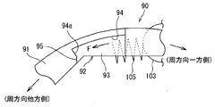
- the present applicant has further proposed a split type so that the above-described one-way clutch cage can be easily manufactured (see Patent Document 2). That is, as shown in FIG. 9, the split type retainer 90 includes a pair of annular portions 91 facing in the axial direction, and a plurality of column portions 92 that are separate from the annular portions 91. In addition, both end portions in the axial direction of the respective pillar portions 92 are assembled by being fitted to both annular portions 91, respectively.
- the annular portion 91 and the column portion 92 can be separately manufactured, and can be individually manufactured, and the cage 90 can be easily manufactured.
- the pillar part 92 has the projection part 96 for supporting the spring outside a figure, the pillar part 92 containing this projection part 96 can be easily manufactured by carrying out injection molding, for example. .
- the cage 90 can be divided to make it easy to manufacture, but the shape of both end portions (column end portion 93) of the column portion 92, and the ring in which the column end portion 93 is fitted.
- the shape of the concave portion 94 of the portion 91 is complicated (see FIG. 10).
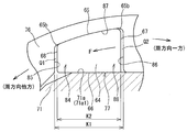
- FIG. 10 is an explanatory view of the column end portion 93 of the split type retainer 90 and the periphery thereof viewed from the axial direction.
- the reason why the shape of the column end portion 93 is complicated is that, as described above, the spring 105 biases the roller 103 toward one side in the circumferential direction, so that the reaction force F toward the other side in the circumferential direction acts on the column portion 92.
- a configuration in which the reaction force F is supported by the annular portion 91 via the column end portion 93 (a configuration in which the reaction force F is transmitted to the annular portion 91) is required. That is, in order for the annular portion 91 to support the reaction force F, a load receiving surface 95 substantially perpendicular to the circumferential direction is formed on the other circumferential side of the column end portion 93, and the load receiving surface 95 is recessed. This is because it is necessary to make contact with the side surface 94a of 94. In addition, the area of the load receiving surface 95 is increased in order to reduce the contact surface pressure between the load receiving surface 95 and the side surface 94a.
- an aspect of the present invention provides a split-type retainer having a simplified configuration, a one-way clutch having the split-type retainer, and a joint for a power generation device including the one-way clutch.
- the purpose is to do.
- a plurality of pockets are formed in the circumferential direction to accommodate the engagement elements between the inner ring and the outer ring of the one-way clutch, and a spring provided in each pocket has the engagement element.
- a split type retainer in which a reaction force on the other side in the circumferential direction acts by being biased in one side in the circumferential direction, and is provided between the inner ring and the outer ring so as to face each other in the axial direction, and a plurality of And a pair of ring portions formed with a gap in the circumferential direction, and a pair of ring portions that are separate from the pair of ring portions and have column end portions that fit into the recesses on both sides in the axial direction.
- a column portion on which the reaction force acts, and the concave portion forms a wedge-shaped space narrowing in the radial direction toward the other circumferential direction between the concave portion and the outer peripheral surface of the inner ring.
- the column end portion has a smaller radial dimension toward the other circumferential side. It has a wedge shape, and provides a split-type cage having a radially inner surface which contacts the outer peripheral surface of the radially outer face and the inner ring in contact with the wedge surface.
- the radial dimension toward the other circumferential direction in the wedge-shaped space narrowed in the radial direction toward the other circumferential direction formed between the wedge surface of the concave portion of the annular portion and the outer peripheral surface of the inner ring, the radial dimension toward the other circumferential direction.
- the column end portion having a wedge shape that decreases becomes fitted. Then, the radially outer surface of the column end contacts the wedge surface of the recess, and the radially inner surface of the column end contacts the outer peripheral surface of the inner ring.
- the spring biases the engagement element in one circumferential direction, and the reaction force (the other reaction force in the circumferential direction) acts on the column portion.
- the wedge-shaped column end portion fits into the wedge-shaped space.
- the reaction force is transmitted from the radially outer side surface and the radially inner side surface of the column end portion to the annular portion and the inner ring, respectively, so that it is provided on the other circumferential side of the column end portion as in the background art.
- a load receiving surface that is substantially orthogonal to is not required. For this reason, the shape of the column end portion is simplified, and the shape of the concave portion of the annular portion into which the column end portion is fitted is also simplified, so that the divided cage is simplified in the configuration of each portion.
- the radially outer surface is preferably a flat surface
- the wedge surface is preferably also a flat surface, whereby the radial outer surface of the column end portion and the wedge surface in contact with the radially outer surface are in contact with each other.
- the shape is simplified.
- the said radial inner surface consists of a plane, and, thereby, the shape of the radial inner surface of a column end part is simplified.
- the circumferential direction dimension of the said recessed part is set larger than the circumferential direction dimension of the said column edge part.
- a circumferential gap is formed between the concave portion and the column end portion, and an operation of assembling the column end portion to the concave portion of the annular portion (an assembly operation of the column portion and the annular portion) is facilitated.
- an inner ring, an outer ring concentric with the inner ring, a plurality of engagement elements provided between the inner ring and the outer ring, and each of the engagement elements are accommodated.
- a plurality of pockets that are formed in the circumferential direction; and a spring that is provided in the pocket and biases the engaging element in one circumferential direction.
- the cage is opposed to the inner ring in the axial direction.
- a pair of annular portions in which a plurality of recesses are formed on the inner peripheral side at intervals in the circumferential direction, and the pair of annular portions are separate from each other.
- a wedge surface for forming a wedge-shaped space narrowing in the radial direction toward the other in the circumferential direction between The column end portion has a wedge shape whose radial dimension decreases toward the other circumferential side, and has a diameter that contacts the outer circumferential surface of the inner ring and the radially outer surface that contacts the wedge surface.
- a one-way clutch having a directional inner surface is provided. According to this aspect, it is possible to reduce the cost of the one-way clutch by including the split-type cage described in (1) in which the configuration of each part is simplified.
- Still another embodiment of the present invention includes a main shaft that rotates by an external force, a rotation transmission mechanism that accelerates the rotation of the main shaft, and an output shaft that outputs the rotation that the rotation transmission mechanism accelerates.
- the joint is used in a power generator that includes a speed increasing device and a generator that has an input shaft that rotates with the rotation of the output shaft as an input, and that generates electric power by rotation of a rotor that rotates integrally with the input shaft.
- a first rotating body that rotates integrally with the output shaft of the speed increaser, a second rotating body that rotates integrally with the input shaft of the generator, and the first rotating body and the second rotating body.
- a one-way clutch (5) disposed between them. According to this aspect, since the one-way clutch (5) is provided, the cost can be reduced even in the joint.
- the configuration of each part is simplified and the manufacture is facilitated.
- the one-way clutch and the joint for the power generation device according to another aspect of the present invention, it is possible to reduce the cost by including the split type cage in which the configuration of each part is simplified.
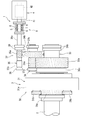
- FIG. 1 is a schematic configuration diagram illustrating a power generation device.
- FIG. 2 is a longitudinal sectional view showing a joint provided in the power generation device and its surroundings.
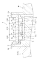
- FIG. 3 is a cross-sectional view of the one-way clutch.
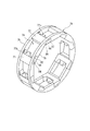
- FIG. 4 is a perspective view showing a cage of the one-way clutch.
- FIG. 5 is a perspective view of an annular portion of the cage.
- FIG. 6 is a perspective view of a pillar portion of the cage.
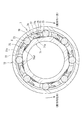
- FIG. 7 is an explanatory view of the column end portion and its periphery viewed from the axial direction.
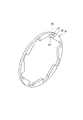
- FIG. 8 is a cross-sectional view of a one-way clutch of the background art.
- FIG. 9 is a perspective view of a split cage of the background art.
- FIG. 10 is an explanatory view of the column end portion and the periphery of the split cage of the background art as viewed from the axial direction.
- FIG. 1 is a schematic configuration diagram showing a power generation device.
- This power generation device is a wind power generation device 1, a main shaft 2 that rotates by receiving wind force (external force), a speed increaser 3 connected to the main shaft 2, and a generator 4 connected to the speed increaser 3.
- the rotation of the main shaft 2 is increased by the speed increaser 3, and the generator 4 is driven by the increased rotation of the shaft to generate power.
- the generator 4 is composed of, for example, an induction generator, and includes an input shaft 41 that rotates with the rotation increased by the speed increaser 3 as an input, a rotor 42 that is built in the generator 4, a stator (not shown), and the like. Have.
- the rotor 42 is coupled to the input shaft 41 so as to be integrally rotatable, and the generator 4 is configured to generate power when the input shaft 41 rotates and the rotor 42 is driven.
- the speed increaser 3 includes a gear mechanism (rotation transmission mechanism) 30 that inputs the rotation of the main shaft 2 and accelerates the rotation.
- the gear mechanism 30 includes a planetary gear mechanism 31 and a high-speed gear mechanism 32 that inputs the rotation accelerated by the planetary gear mechanism 31 and further accelerates the rotation.
- the planetary gear mechanism 31 includes an internal gear (ring gear) 31a, a plurality of planetary gears 31b held by a planet carrier (not shown) coupled to the main shaft 2 so as to be integrally rotatable, and a sun gear 31c meshing with the planetary gear 31b. have.
- the sun gear 31 c rotates through the planetary gear 31 b, and the rotation is transmitted to the low speed shaft 33 of the high speed gear mechanism 32.
- the high speed gear mechanism 32 includes a low speed shaft 33 having a low speed gear 33a, an intermediate shaft 34 having a first intermediate gear 34a and a second intermediate gear 34b, and an output shaft 35 having a high speed gear 35a.
- the low speed shaft 33 is a large rotating shaft having a diameter of about 1 m, for example, and is disposed concentrically with the main shaft 2. Both axial ends of the low speed shaft 33 are rotatably supported by roller bearings 36a and 36b.
- the intermediate shaft 34 is disposed in parallel with the low-speed shaft 33, and both axial ends thereof are rotatably supported by roller bearings 37a and 37b.
- the first intermediate gear 34a of the intermediate shaft 34 meshes with the low speed gear 33a, and the second intermediate gear 34b meshes with the high speed gear 35a.
- the output shaft 35 is disposed in parallel with the intermediate shaft 34 and outputs rotational torque.
- One end portion 35b and the other end portion (output end portion) 35c side of the output shaft 35 are rotatably supported by roller bearings 38 and 39, respectively.
- the rotation of the main shaft 2 is made in three stages depending on the gear ratio of the planetary gear mechanism 31, the gear ratio between the low speed gear 33a and the first intermediate gear 34a, and the gear ratio between the second intermediate gear 34b and the high speed gear 35a. And output from the output shaft 35. That is, the rotation of the main shaft 2 by wind power is increased in three stages by the speed increaser 3 and output from the output shaft 35, and the generator 4 is driven by the rotational torque of the output shaft 35.
- the wind turbine generator 1 includes a joint 9 for connecting the output shaft 35 of the speed increaser 3 and the input shaft 41 of the generator 4.
- FIG. 2 is a longitudinal sectional view showing the joint 9 and its surroundings.
- the joint 9 is provided in a region between the output shaft 35 and the input shaft 41 so that torque can be transmitted between the output shaft 35 and the input shaft 41.
- the joint 9 includes a first rotating body 5, a second rotating body 6, a one-way clutch 7, and a rolling bearing 8.
- the one-way clutch 7 and the rolling bearing 8 are disposed between the first rotating body 5 and the second rotating body 6.
- the first rotating body 5 is a shaft member arranged concentrically with the output shaft 35, from its one axial end (left end in FIG. 2) toward the other axial end (right end in FIG. 2).
- the flange portion 51, the large diameter portion 52, and the small diameter portion 53 are provided in this order.
- the flange portion 51 is detachably fixed to the end flange 35 d of the output shaft 35, and the first rotating body 5 rotates integrally with the output shaft 35.
- the second rotating body 6 is disposed concentrically on the radially outer side of the first rotating body 5, and has a cylindrical portion 61 and a flange portion 62 provided at the other axial end of the cylindrical portion 61. is doing.
- the second rotating body 6 is disposed on the radially outer side of the first rotating body 5.
- the first rotating body 5 has a cylindrical shape and is disposed on the radially inner side of the first rotating body 5. May be.
- the flange portion 62 is detachably fixed to the end flange 41 a of the input shaft 41, and the second rotating body 6 rotates integrally with the input shaft 41.
- An inner peripheral surface of the cylindrical portion 61 is a cylindrical surface, and an annular seal member 10 is provided between one axial end portion of the cylindrical portion 61 and the large diameter portion 52 of the first rotating body 5. ing.
- Each rolling bearing 8 is disposed between the small-diameter portion 53 of the first rotating body 5 and the cylindrical portion 61 of the second rotating body 6, and can relatively rotate the first rotating body 5 and the second rotating body 6.
- Each rolling bearing 8 is formed of a cylindrical roller bearing, and includes an inner ring 81 and an outer ring 82, and a plurality of cylindrical rollers 83 disposed between the inner ring 81 and the outer ring 82 so as to be able to roll.
- a region A and a region C at both ends in the axial direction of the cylindrical portion 61 of the second rotating body 6 have a function as the outer ring 82 of the rolling bearing 8, and an outer ring is provided on each inner peripheral surface of the regions A and C.
- outer ring raceway surface 82a is formed.
- a cylindrical roller 83 is disposed between the outer ring raceway surface 82a and an inner ring raceway surface 81a formed on the outer periphery of the inner ring 81 so as to allow rolling.
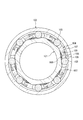
- FIG. 3 is a cross-sectional view of the one-way clutch 7. 2 and 3, the one-way clutch 7 is provided between an inner ring 71, an outer ring 72 that is concentric with the inner ring 71, and an outer peripheral surface 71 a of the inner ring 71 and an inner peripheral surface 72 a of the outer ring 72.
- a spring 75 that urges elastically (clockwise).
- the inner ring 71 is externally fitted and fixed to the central portion in the axial direction of the small-diameter portion 53 of the first rotating body 5 (see FIG. 2), and rotates integrally with the first rotating body 5.
- a region B in the central portion in the axial direction of the cylindrical portion 61 of the second rotating body 6 has a function as the outer ring 72 of the one-way clutch 7.
- the rollers 73 have a cylindrical shape, and eight rollers 73 are arranged in the circumferential direction in this embodiment.
- the spring 75 is a compression coil spring and is individually accommodated in each pocket 78 of the retainer 74.
- the second rotating body 6 is used as the outer ring 72 of the one-way clutch 7 and the outer ring 82 of the rolling bearing 8, but these outer rings 72 and 82 are separated from the second rotating body 6. You may have.
- the same number (eight) of flat (planar) cam surfaces 71a1 as the rollers 73 are formed on the outer peripheral surface 71a of the inner ring 71, and the inner peripheral surface 72a of the outer ring 72 is a cylindrical surface. ing.
- a plurality (eight) of wedge-shaped spaces S are formed in the circumferential direction between the cam surface 71a1 and the inner peripheral surface 72a.
- the roller 73 and the spring 75 are individually arranged in each wedge-shaped space S, and the spring 75 biases the roller 73 in a direction (one circumferential direction) in which the wedge-shaped space S is narrowed.
- the outer peripheral surface of the roller 73 is a contact surface that contacts the cam surface 71a1 and the inner peripheral surface 72a, and this contact surface is formed straight in the width direction (axial direction).
- the rotation speed of the first rotating body 5 tends to exceed the rotation speed of the second rotating body 6.
- the inner ring 71 tends to rotate relative to the outer ring 72 in one direction (clockwise direction in FIG. 3).
- the roller 73 slightly moves in the direction in which the wedge-shaped space S is narrowed by the urging force of the spring 75, and the contact surface (outer peripheral surface) of the roller 73 becomes the outer peripheral surface 71 a (cam surface 71 a 1) of the inner ring 71.
- the roller 73 comes into pressure contact with the inner peripheral surface 72 a of the outer ring 72, and the roller 73 is engaged between the inner and outer rings 71, 72.
- the inner and outer rings 71 and 72 can be integrally rotated in the one direction, and the first rotating body 5 and the second rotating body 6 are connected so as to be integrally rotatable. As a result, the output shaft 35 and the input shaft 41 can be rotated together.
- the rollers 73 are connected to the inner and outer rings 71, 71. 72 is held in a meshed state. Therefore, the one-way clutch 7 maintains the integral rotation of the inner and outer rings 71 and 72 in the one direction, and the first rotating body 5 and the second rotating body 6 (the output shaft 35 and the input shaft 41) are integrated. Continue to rotate.
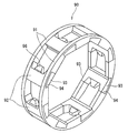
- FIG. 4 is a perspective view showing the retainer 74 of the one-way clutch 7.
- the retainer 74 is a split retainer and includes a pair of annular portions 76 that are opposed in the axial direction and a plurality of column portions 77 that are separate from the annular portions 76. Both end portions (column end portions 64) in the axial direction of each column portion 77 are fitted into recesses 84 described later provided in both annular portions 76, whereby the column portion 77 has a pair of annular portions 76. Link. Pockets 78 are formed between both annular portions 76 and column portions 77 adjacent in the circumferential direction, and rollers 73 are accommodated in the respective pockets 78 (see FIG. 3). Thereby, the holder
- FIG. 5 is a perspective view of the annular portion 76 included in the retainer 74.
- the annular portion 76 is made of a metal such as carbon steel or aluminum, and is, for example, an annular member having an outer diameter of 300 mm and an axial thickness of 15 mm.
- a pair of annular portions 76 are provided in the axial direction between the inner ring 71 and the outer ring 72 of the one-way clutch 7 (see FIG. 3).
- a plurality of recesses 84 are formed at intervals in the circumferential direction on the inner peripheral side of each annular portion 76.
- Each recessed part 84 has the 1st side surface 85 and the 2nd side surface 86 which exist in the circumferential direction both sides, and the wedge surface 87 which is provided between these side surfaces 85 and 86 and faces the radial direction inner side.
- FIG. 6 is a perspective view of the column portion 77 included in the retainer 74.
- the column part 77 is produced by injection molding a synthetic resin material.
- the column part 77 includes a main body part 77a, a protrusion part 77b provided to project from one circumferential end surface of the main body part 77a, and a pair of column end parts 64 provided on both sides in the axial direction of the main body part 77a. And have.
- the protrusion 77b is for supporting the spring 75 at a predetermined position in the pocket 78, and the coiled spring 75 is externally fitted to the protrusion 77b.
- the column end portion 64 is formed to have a smaller radial thickness (vertical direction in the drawing) than the main body portion 77a, and between the outer peripheral surface of the column end portion 64 and the outer peripheral surface of the main body portion 77a.
- a step surface 77d is formed.
- the annular portion 76 and the column portion 77 constituting the cage 74 are separated, the annular portion 76 and the column portion 77 are individually manufactured. be able to. Therefore, it can be easily manufactured as compared with the case where the entire cage is manufactured integrally.
- FIG. 7 is an explanatory view of the column end portion 64 of the column portion 77 and the periphery thereof viewed from the axial direction. An arrow F shown in FIG. 7 indicates the reaction force.
- the reaction force F by the spring 75 acts on the annular portion 76 via the column end portion 64.
- the concave portion 84 formed in the annular portion 76 has a wedge surface 87 facing radially inward, and the wedge surface 87 causes the outer periphery of the inner ring 71 to be formed in the concave portion 84.
- a wedge-shaped space 88 that narrows in the radial direction toward the other circumferential direction is formed between the surface 71a and the surface 71a.
- the concave portion 84 has the first side surface 85 and the second side surface 86 located on both sides in the circumferential direction of the wedge surface 87, and the concave portion 84 opens radially inward by these surfaces. It has a notch shape.
- the column end portion 64 fitted in the concave portion 84 has a wedge shape corresponding to the wedge-shaped space 88. That is, the column end portion 64 has a wedge shape in which the radial dimension gradually decreases toward the other circumferential direction so as to correspond to the wedge-shaped space 88 (see FIGS. 6 and 7).
- the column end portion 64 of this embodiment has a substantially trapezoidal shape (having a circular arc portion 65b at a corner) when viewed from a direction parallel to the axial direction of the cage 74, and is in the radial direction in contact with the wedge surface 87.
- the side surfaces 67 and 68 are surfaces that extend in the radial direction, and are substantially parallel to each other, but the radially outer surface 65 is an inclined surface that approaches the radially inner side surface 66 toward the other circumferential direction on the entire surface. It has become.
- the column end 64 having a wedge shape is fitted into the wedge-shaped space 88, the radially outer surface 65 of the column end 64 contacts the wedge surface 87 of the recess 84, and the outer peripheral surface 71 a of the inner ring 71.
- the inner surface 66 in the radial direction of the column end portion 64 contacts the cam surface 71a1.
- the force F is transmitted from the radially outer side surface 65 and the radially inner side surface 66 of the column end portion 64 to the annular portion 76 and the inner ring 71, respectively.
- the column portion 77 is positioned in the circumferential direction by the radial outer surface 65 and the radial inner surface 66 that are in contact with the wedge surface 87 and the cam surface 71a1.
- the load receiving surface 95 provided on the other circumferential side of the column end portion 93 as in the background art (see FIG. 10) becomes unnecessary.
- the load receiving surface 95 is a surface that is substantially orthogonal to the circumferential direction and contacts the side surface 94a of the recess 94, and receives the reaction force F of the spring 105.
- the shape of the column end portion 64 is simplified, and the shape of the concave portion 84 of the annular portion 76 into which the column end portion 64 is fitted is also simplified.
- the split type retainer 74 is simplified.
- the radially outer surface 65 of the column end portion 64 may be a circular arc surface having a large radius that protrudes radially outward, but is formed of a flat surface.
- the wedge surface 87 in contact with may also be a circular arc surface with a large radius that protrudes radially outward, but is a flat surface.
- the cam surface 71a1 of the inner ring 71 is a flat surface, and the radially inner side surface 66 that is in contact with the cam surface 71a1 is a flat surface.
- the first circumferential side surface 67 and the second circumferential side surface 68 of the column end portion 64 are also flat, and the first side surface 85 and the second side 86 of the concave portion 84 are also flat.
- the column end portion 64 of the present embodiment has a substantially trapezoidal shape when viewed from the direction parallel to the axial direction of the cage 74, and in particular, the radial outer surface 65 of the column end portion 64 and the recess 84.
- the shape of the wedge surface 87 and the shape of the radially inner side surface 66 of the column end portion 64 are simplified as compared with the background art, and the column portion 77 and the annular portion 76 can be easily manufactured.
- the circular arc portion 65b that protrudes outward in the radial direction is interposed between the radial outer surface 65 and the side surfaces 67 and 68, the column end portion 64 is held.
- it When viewed from a direction parallel to the axial direction of the vessel 74, it has a substantially trapezoidal shape with arc portions 65b at the corners.
- the circumferential dimension K1 of the recess 84 is set to be larger than the circumferential dimension K2 of the column end portion 64 (K1> K2). For this reason, circumferential gaps Q ⁇ b> 1 and Q ⁇ b> 2 are formed between the recess 84 and the column end portion 64. In particular, even when the column end portion 64 is pushed in the other circumferential direction by the reaction force F and moves in the recess 84 (wedge-shaped space 88), the recess Q is formed so that the gap Q1 formed on the other circumferential side remains.
- the dimensions of 84 and the column end 64 are set.
- the column end portion 64 Since the circumferential gaps Q1 and Q2 are formed between the recess 84 and the column end portion 64, the column end portion 64 is connected to the ring portion 76 in the assembly of the ring portion 76 and the column portion 77. The operation of fitting into the recess 84 is facilitated. Further, the column end portion 64 only needs to have the wedge shape as described above, and it is not necessary to form the column end portion 64 and the concave portion 84 by performing fine dimensional management, and the column portion 77 and the annular portion. 76 can be easily manufactured.
- the one-way clutch 7 shown in FIG. 2 includes the split type retainer 74 in which the structures of the column part 77 and the annular part 76 are simplified, and thus the cost can be reduced. Since the joint 9 shown in FIG. 1 has the one-way clutch 7 provided with the split type retainer 74, the cost of the joint 9 can be reduced.
- one annular portion 76 is composed of one annular member has been described, but a plurality of annular members (not shown) are overlapped in the axial direction.
- One annular portion 76 may be configured.
- a convex portion is formed on one annular member, and a concave portion in which the convex portion is fitted is formed on another annular member stacked on the annular member, and a plurality of annular members are fixed to each other.
- Two annular portions 76 are formed.
- the column end portion 64 has four surfaces (65, 66, 67, 68) to form a contour, and the shape of the column end portion 64 (in side view).
- the column end portion 64 only has to have a radially outer surface 65 and a radially inner surface 66 to form a wedge shape.
- the circumferential side surface (68) on the other circumferential side may be omitted (or made extremely narrow compared to other surfaces), and the shape of the column end portion 64 may be substantially triangular.
- the present invention is not limited to the above-described embodiment, and can be implemented with appropriate modifications.
- the annular portion 76 of the retainer 74 is made of metal, but the annular portion 76 may be formed of synthetic resin. In this case, the annular portion 76 can be easily manufactured by injection molding a synthetic resin material.
- the joint 9 for power generators of the said embodiment was illustrated as a joint for the wind power generator 1 which uses a wind force as external force, it is applied also to the power generator which generates electric power using other external forces, such as hydraulic power and a thermal power. be able to.
- the one-way clutch 7 according to the embodiment of the present invention can be applied to devices other than the power generator.
Landscapes
- Engineering & Computer Science (AREA)
- General Engineering & Computer Science (AREA)
- Mechanical Engineering (AREA)
- Wind Motors (AREA)
- Rolling Contact Bearings (AREA)
- Connection Of Motors, Electrical Generators, Mechanical Devices, And The Like (AREA)
Priority Applications (5)
| Application Number | Priority Date | Filing Date | Title |
|---|---|---|---|
| EP14874291.9A EP3101298B1 (en) | 2013-12-25 | 2014-12-24 | Divided holder, one-way clutch, and joint for power-generating device |
| ES14874291T ES2751409T3 (es) | 2013-12-25 | 2014-12-24 | Soporte dividido, embrague unidireccional, y junta para dispositivo de generación de energía |
| DK14874291T DK3101298T3 (da) | 2013-12-25 | 2014-12-24 | Delt holder, envejskobling, og samling til strømforsyningsindretning |
| US15/106,868 US9845835B2 (en) | 2013-12-25 | 2014-12-24 | Split type cage, one-way clutch and joint for power-generation device |
| CN201480070561.7A CN105849430B (zh) | 2013-12-25 | 2014-12-24 | 分割型保持器、单向离合器和用于发电装置的接头 |
Applications Claiming Priority (2)
| Application Number | Priority Date | Filing Date | Title |
|---|---|---|---|
| JP2013267275A JP6273832B2 (ja) | 2013-12-25 | 2013-12-25 | 分割型保持器、一方向クラッチ及び発電装置用の継手 |
| JP2013-267275 | 2013-12-25 |
Publications (1)
| Publication Number | Publication Date |
|---|---|
| WO2015098925A1 true WO2015098925A1 (ja) | 2015-07-02 |
Family
ID=53478777
Family Applications (1)
| Application Number | Title | Priority Date | Filing Date |
|---|---|---|---|
| PCT/JP2014/084070 WO2015098925A1 (ja) | 2013-12-25 | 2014-12-24 | 分割型保持器、一方向クラッチ及び発電装置用の継手 |
Country Status (7)
Families Citing this family (3)
| Publication number | Priority date | Publication date | Assignee | Title |
|---|---|---|---|---|
| KR101873277B1 (ko) * | 2017-01-12 | 2018-08-02 | (주)리얼감 | 클러치 유닛 |
| DE102021120521B3 (de) * | 2021-08-06 | 2022-07-28 | Schaeffler Technologies AG & Co. KG | Freilauf mit formschlüssiger Verbindung zwischen Blechkäfig und Freilaufkörper mit Kopplungsscheibe |
| CN118149025B (zh) * | 2024-05-10 | 2024-08-06 | 宁波东煌轴承有限公司 | 一种单向轴承 |
Citations (3)
| Publication number | Priority date | Publication date | Assignee | Title |
|---|---|---|---|---|
| US3877555A (en) * | 1973-06-22 | 1975-04-15 | Ferodo Sa | Assembly cage for free-wheel or bearing |
| JP2013060825A (ja) | 2011-09-12 | 2013-04-04 | Jtekt Corp | 発電装置 |
| JP2013231448A (ja) | 2012-04-27 | 2013-11-14 | Jtekt Corp | 一方向クラッチ及び発電装置 |
Family Cites Families (20)
| Publication number | Priority date | Publication date | Assignee | Title |
|---|---|---|---|---|
| FR1287491A (fr) * | 1961-01-31 | 1962-03-16 | Renault | Roue libre à rouleaux |
| US4613763A (en) | 1984-12-24 | 1986-09-23 | Swansen Theodore L | Wind driven electric power generating system |
| US4787490A (en) * | 1987-06-15 | 1988-11-29 | General Motors Corporation | Metal and plastic combination roller clutch cage |
| JPH04344198A (ja) | 1991-05-20 | 1992-11-30 | Mitsubishi Heavy Ind Ltd | 同期発電装置 |
| JP3604489B2 (ja) | 1996-02-22 | 2004-12-22 | 光洋精工株式会社 | 軸受装置およびそれを備える補機駆動用プーリ装置 |
| FR2747444B1 (fr) | 1996-04-16 | 1998-05-15 | Skf France | Montage de roue libre |
| KR100269764B1 (ko) | 1996-11-30 | 2000-10-16 | 심현진 | 풍력 발전 장치 |
| JP2001349335A (ja) | 2000-06-07 | 2001-12-21 | Daido Seimitsu Kogyo Kk | フレキシブル継手 |
| US7370741B2 (en) | 2002-01-21 | 2008-05-13 | Nsk Ltd. | Engine start roller clutch-housed type rotation transmission device |
| US6856042B1 (en) | 2003-10-09 | 2005-02-15 | Hisaomi Kubota | Wind turbine generator |
| JP2006097713A (ja) | 2004-09-28 | 2006-04-13 | Jtekt Corp | 一方向クラッチ |
| JP2006183755A (ja) | 2004-12-27 | 2006-07-13 | Jtekt Corp | 動力伝達装置 |
| JP4738027B2 (ja) | 2005-03-10 | 2011-08-03 | 三菱重工業株式会社 | 風力発電装置の軸カップリング構造 |
| FR2913081B1 (fr) | 2007-02-27 | 2009-05-15 | Skf Ab | Dispositif de poulie debrayable |
| US7851933B2 (en) | 2007-03-15 | 2010-12-14 | Duffey Christopher K | System for generating constant speed output from variable speed input |
| US8932017B2 (en) | 2010-08-18 | 2015-01-13 | Ebo Group, Inc. | Wind turbine torque limiting clutch system |
| US9097239B2 (en) | 2010-08-18 | 2015-08-04 | Ebo Group, Inc. | Wind turbine torque limiting clutch system |
| CN202182109U (zh) * | 2011-08-10 | 2012-04-04 | 浙江五洲新春集团有限公司 | 单向轴承及保持架 |
| US9035476B2 (en) | 2011-09-12 | 2015-05-19 | Jtekt Corporation | Power generating device |
| DE102012208057A1 (de) * | 2012-05-14 | 2013-11-14 | Schaeffler Technologies AG & Co. KG | Freilaufkäfig |
-
2013
- 2013-12-25 JP JP2013267275A patent/JP6273832B2/ja not_active Expired - Fee Related
-
2014
- 2014-12-24 WO PCT/JP2014/084070 patent/WO2015098925A1/ja active Application Filing
- 2014-12-24 CN CN201480070561.7A patent/CN105849430B/zh not_active Expired - Fee Related
- 2014-12-24 ES ES14874291T patent/ES2751409T3/es active Active
- 2014-12-24 DK DK14874291T patent/DK3101298T3/da active
- 2014-12-24 US US15/106,868 patent/US9845835B2/en not_active Expired - Fee Related
- 2014-12-24 EP EP14874291.9A patent/EP3101298B1/en not_active Not-in-force
Patent Citations (3)
| Publication number | Priority date | Publication date | Assignee | Title |
|---|---|---|---|---|
| US3877555A (en) * | 1973-06-22 | 1975-04-15 | Ferodo Sa | Assembly cage for free-wheel or bearing |
| JP2013060825A (ja) | 2011-09-12 | 2013-04-04 | Jtekt Corp | 発電装置 |
| JP2013231448A (ja) | 2012-04-27 | 2013-11-14 | Jtekt Corp | 一方向クラッチ及び発電装置 |
Also Published As
| Publication number | Publication date |
|---|---|
| EP3101298A1 (en) | 2016-12-07 |
| CN105849430B (zh) | 2019-01-15 |
| JP6273832B2 (ja) | 2018-02-07 |
| US20170037913A1 (en) | 2017-02-09 |
| EP3101298B1 (en) | 2019-08-14 |
| CN105849430A (zh) | 2016-08-10 |
| EP3101298A4 (en) | 2017-08-16 |
| DK3101298T3 (da) | 2019-11-11 |
| JP2015124778A (ja) | 2015-07-06 |
| ES2751409T3 (es) | 2020-03-31 |
| US9845835B2 (en) | 2017-12-19 |
Similar Documents
| Publication | Publication Date | Title |
|---|---|---|
| JP2013231448A (ja) | 一方向クラッチ及び発電装置 | |
| KR101724659B1 (ko) | 역 사이클로이드 감속기 | |
| WO2015098925A1 (ja) | 分割型保持器、一方向クラッチ及び発電装置用の継手 | |
| CN108368933A (zh) | 传动装置和具有传动装置的驱动单元 | |
| EP3101276A1 (en) | Joint member for wind power generation apparatus, and wind power generation apparatus | |
| WO2015111639A1 (ja) | 分割型保持器及び発電装置用の継手 | |
| JP2017137896A (ja) | 転がり軸受の固定支持構造 | |
| JP5822383B2 (ja) | 減速装置 | |
| JP6090502B2 (ja) | 一方向クラッチ及び発電装置 | |
| JP5849645B2 (ja) | 摩擦ローラ式減速機 | |
| JP2013053713A (ja) | ころ軸受及び風力発電用増速機 | |
| JP2017201194A (ja) | 減速装置 | |
| JP5601420B2 (ja) | 無段変速機 | |
| JP6265061B2 (ja) | 遊星ローラ式トラクションドライブ装置 | |
| JP6568749B2 (ja) | 遊星ローラ式の動力伝達装置 | |
| JP6097045B2 (ja) | トラクションドライブ機構 | |
| JP5970990B2 (ja) | 遊星ロ−ラ型動力伝達装置 | |
| JP2012193792A (ja) | 摩擦ローラ式減速機及び電気自動車用駆動装置 | |
| JP2015129544A (ja) | 一方向クラッチ、発電装置用の継手、及び風力発電装置 | |
| JP2013036526A (ja) | ころ軸受用保持器 | |
| JP6713363B2 (ja) | 変速機 | |
| JP2014020527A (ja) | 円筒ころ軸受 | |
| JP2012127457A (ja) | 無段変速機 | |
| JP2018066450A (ja) | 遊星歯車装置 | |
| JP2017031994A (ja) | 無段変速機 |
Legal Events
| Date | Code | Title | Description |
|---|---|---|---|
| 121 | Ep: the epo has been informed by wipo that ep was designated in this application |
Ref document number: 14874291 Country of ref document: EP Kind code of ref document: A1 |
|
| WWE | Wipo information: entry into national phase |
Ref document number: 15106868 Country of ref document: US |
|
| REEP | Request for entry into the european phase |
Ref document number: 2014874291 Country of ref document: EP |
|
| WWE | Wipo information: entry into national phase |
Ref document number: 2014874291 Country of ref document: EP |
|
| NENP | Non-entry into the national phase |
Ref country code: DE |