WO2015098809A1 - 加工容器及びレーザ加工装置 - Google Patents
加工容器及びレーザ加工装置 Download PDFInfo
- Publication number
- WO2015098809A1 WO2015098809A1 PCT/JP2014/083856 JP2014083856W WO2015098809A1 WO 2015098809 A1 WO2015098809 A1 WO 2015098809A1 JP 2014083856 W JP2014083856 W JP 2014083856W WO 2015098809 A1 WO2015098809 A1 WO 2015098809A1
- Authority
- WO
- WIPO (PCT)
- Prior art keywords
- plate
- adjacent
- front plate
- processing container
- side edge
- Prior art date
- Legal status (The legal status is an assumption and is not a legal conclusion. Google has not performed a legal analysis and makes no representation as to the accuracy of the status listed.)
- Ceased
Links
Images





Classifications
-
- B—PERFORMING OPERATIONS; TRANSPORTING
- B23—MACHINE TOOLS; METAL-WORKING NOT OTHERWISE PROVIDED FOR
- B23K—SOLDERING OR UNSOLDERING; WELDING; CLADDING OR PLATING BY SOLDERING OR WELDING; CUTTING BY APPLYING HEAT LOCALLY, e.g. FLAME CUTTING; WORKING BY LASER BEAM
- B23K26/00—Working by laser beam, e.g. welding, cutting or boring
- B23K26/12—Working by laser beam, e.g. welding, cutting or boring in a special environment or atmosphere, e.g. in an enclosure
- B23K26/127—Working by laser beam, e.g. welding, cutting or boring in a special environment or atmosphere, e.g. in an enclosure in an enclosure
-
- B—PERFORMING OPERATIONS; TRANSPORTING
- B23—MACHINE TOOLS; METAL-WORKING NOT OTHERWISE PROVIDED FOR
- B23K—SOLDERING OR UNSOLDERING; WELDING; CLADDING OR PLATING BY SOLDERING OR WELDING; CUTTING BY APPLYING HEAT LOCALLY, e.g. FLAME CUTTING; WORKING BY LASER BEAM
- B23K26/00—Working by laser beam, e.g. welding, cutting or boring
- B23K26/02—Positioning or observing the workpiece, e.g. with respect to the point of impact; Aligning, aiming or focusing the laser beam
- B23K26/035—Aligning the laser beam
-
- G—PHYSICS
- G02—OPTICS
- G02B—OPTICAL ELEMENTS, SYSTEMS OR APPARATUS
- G02B26/00—Optical devices or arrangements for the control of light using movable or deformable optical elements
- G02B26/08—Optical devices or arrangements for the control of light using movable or deformable optical elements for controlling the direction of light
- G02B26/10—Scanning systems
- G02B26/105—Scanning systems with one or more pivoting mirrors or galvano-mirrors
Definitions
- the present invention relates to a processing container that supports a head portion that scans a processing surface of a processing object with laser light, and a laser processing apparatus that includes the head portion and the processing container.
- the defect cause determination apparatus described in Patent Document 1 below includes an XY stage that can move in the X-axis direction and the Y-axis direction, a sample chamber that houses the XY stage, and the surface of the sample placed on the XY stage.
- the defect cause determination apparatus includes a CCD video camera that photographs the sample surface on the XY stage, and the user confirms the position of the visible laser light photographed by the CCD camera on the sample surface on the monitor and displays the XY stage. It is configured to operate and align the sample.
- the present invention has been made to solve the above-described problems, and a small processing container and laser capable of safely and easily confirming the irradiation position of a visible laser beam on a processing object.
- An object is to provide a processing apparatus.
- a processing container includes an oscillator that emits laser light, a visible laser light source that emits visible laser light, a laser light emitted from the oscillator, and a laser beam emitted from the visible laser light source.
- the processing container includes the condensing unit Formed on the emission direction side of the unit, and a processing table on which a workpiece is arranged, a hole that supports the head unit and through which the laser beam and the visible laser beam emitted from the light collecting unit pass are formed.
- the front plate is configured to be openable and closable, and the adjacent side plate is oriented in a direction approaching the front plate from a perpendicular extending from the optical axis of the light collecting unit to the adjacent side plate.
- the adjacent side plate When the front plate is opened, the adjacent side plate is visible from a portion through which a perpendicular extending from at least the optical axis of the adjacent side portion to the adjacent side portion passes. Light is passing through. It should be noted that the visible light is not limited to the case where the adjacent side plate is removed from the adjacent side surface portion and the visible light passes, but the visible light passes through the light shielding film that shields the laser light and transmits the visible light. The case of passing is also included.
- the user can confirm the irradiation position of the visible laser beam on the workpiece from the direction facing the front plate of the processing table by opening the front plate. Further, the user can confirm the irradiation position of the visible laser beam on the object to be processed through the near side surface portion from the perpendicular direction extending from the optical axis of the light collecting portion to the adjacent side surface plate. In other words, the user can easily confirm the irradiation position of the visible laser beam on the workpiece placed on the machining table from the two-axis directions orthogonal to the optical axis of the light collecting unit by opening the front plate.
- the alignment of the processing object with respect to the visible laser beam and the laser beam can be performed quickly.
- the laser light reflected on the object to be processed can be blocked by the front plate and the adjacent side plate, and the user can perform the work safely.
- the irradiation position of the visible laser beam on the workpiece placed on the processing table can be visually adjusted with a simple configuration without installing a camera or the like, and the processing container can be downsized. Can do.
- the processing container may include a rotation support portion that rotatably supports the adjacent side plate with a side edge portion of the adjacent side plate opposite to the front plate as a rotation axis. Good.
- the upper surface member includes an adjacent upper surface plate that covers a ceiling portion of the processing container in a direction approaching the front plate from a perpendicular extending from the optical axis of the light collecting unit to the adjacent side surface plate.
- a side edge portion of the adjacent upper surface plate on the side of the front plate is fixed to a side edge portion of the front surface plate on the side of the adjacent upper surface plate, and is opposite to the front plate of the adjacent upper surface plate.
- the side edge portion may be separated from the opposite side edge portion of the upper surface member.
- the side edge portions on the front plate side of the adjacent side plates adjacent to both side edge portions of the front plate are respectively fixed to the side edge portions of the adjacent front plates.
- the face plate and the adjacent upper surface plate are separated along a perpendicular extending from the optical axis of the light collecting portion to the front plate, and the rotation support portion is fixed to each side edge of the front plate.
- the adjacent side plate may be rotatably supported using each side edge portion of the adjacent side plate opposite to the front plate as a rotation axis.
- the processing container includes a cover member formed by the front plate and the adjacent side plate, a main body box having the processing base and the upper surface member, and the cover member being detachably provided.
- One side edge of the adjacent side plate on the side of the front plate is fixed to a side edge of the front side plate on the side of the adjacent side plate, and the cover member is the front plate of the adjacent side plate
- the main body box portion is formed on a side edge portion opposite to the other side edge portion of the adjacent side plate.
- the engaging portion may be configured to be engageable with the engaging portion.
- the cover member has an adjacent upper surface plate that covers the ceiling portion of the processing container in a direction approaching the front plate from the optical axis of the light collecting portion, and the adjacent upper surface plate faces the front plate.
- the side edge portion to be fixed to the side edge portion on the adjacent upper surface plate side of the front plate, and the side edge portion on the side opposite to the front plate of the adjacent upper surface plate is opposed to the upper surface member. It may be separated from the side edge.
- the processing container includes a cover member formed by the front plate and the adjacent side plate, a main body box portion having the processing base and the upper surface member, and the cover member being provided to be openable and closable.
- One side edge portion of the adjacent side plate on the side of the front plate is fixed to a side edge portion of the front plate on the side of the adjacent side plate, and the main body box portion is connected to the front side plate of the adjacent side plate.
- the cover member is formed along a side of the optical axis by sliding on the other side edge of the adjacent side plate. You may have the slide support part supported so that a slide movement is possible.
- the adjacent side plate closes the through hole and transmits light, and is formed at a position where a perpendicular extending from the optical axis of the light collecting portion to the adjacent side plate passes.
- a light-transmitting plate, and the light-transmitting plate may be provided with a light-shielding film that blocks the laser light and transmits the visible light.
- the laser processing apparatus includes an oscillator that emits laser light, a visible laser light source that emits visible laser light, a laser light that is emitted from the oscillator, and a visible laser that is emitted from the visible laser light source.
- a condensing unit that collects light and emits the light toward a workpiece, and a box-shaped processing container that supports the head unit, and the processing container includes: A processing base on which the processing target is placed and a head that supports the head unit and through which the laser beam and the visible laser beam emitted from the focusing unit pass, are provided on the emission direction side of the focusing unit.
- the top member and the plurality of members are formed of a light shielding material that shields the laser beam reflected on the object to be processed, and the plurality of side members are a front plate that is one surface of the plurality of side surfaces, and the front plate.
- the adjacent side plate is configured to be openable and closable, and the adjacent side plate approaches the front plate from a perpendicular extending from the optical axis of the light collecting unit to the adjacent side plate.
- the adjacent side plate is a portion through which a perpendicular extending from at least the optical axis of the adjacent side plate to the adjacent side plate passes when the front plate is opened. Visible laser light is passed through.
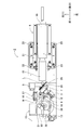
- FIG. 3 is a plan view showing a schematic configuration of a laser head unit 2.
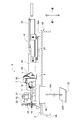
- FIG. 2 is a side view showing a schematic configuration of a laser head unit 2.
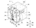
- FIG. 3 is a perspective view of a processing container 3.
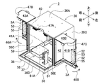
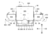
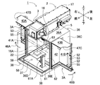
- FIG. 5 is a plan view of FIG. 4. It is a perspective view in the state where door 3A of processing container 3 was opened.
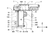
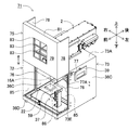
- FIG. 7 is a plan view of FIG. 6. It is a perspective view explaining the alignment method of the process target object. It is a side view explaining the alignment method of the process target object. It is a perspective view which shows the state which slid the slide door 75 of the laser processing apparatus 71 which concerns on 2nd Embodiment upwards.
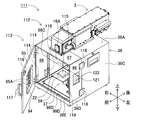
- FIG. 14 is a side view of FIG. 13. It is a perspective view which shows the state which opened the front board 95 of the laser processing apparatus 111 which concerns on 4th Embodiment.
- FIG. 16 is a side view of FIG. 15.
- FIG. 1 a schematic configuration of the laser processing apparatus 1 according to the first embodiment will be described with reference to FIGS. 1 to 7.
- the double door 3 ⁇ / b> A side of the box-shaped processing container 3 is the front direction
- the back side with respect to the door 3 ⁇ / b> A of the processing container 3 is the rear direction.
- the optical axis 16A direction of the f ⁇ lens 16 is the vertical direction
- the upper surface plate portion 36A side that supports the laser head portion 2 of the processing container 3 is the upper side.
- the direction orthogonal to the up-down direction and the front-back direction of the laser processing apparatus 1 is the left-right direction of the laser processing apparatus 1.
- the laser processing apparatus 1 includes a laser head portion 2 that emits laser light L and visible laser light M (see FIG. 2) coaxially from an f ⁇ lens 16, and the laser head portion 2 is an upper surface plate portion. It is comprised from the substantially box-shaped processing container 3 fixed on 36A.
- the laser head unit 2 includes a main body base 5, a laser oscillation unit 6 that emits laser light L, an optical shutter unit 7, an optical damper 8, a half mirror 9, and a guide.
- the optical unit 11, the reflection mirror 12, the optical sensor 13, the galvano scanner 15, the f ⁇ lens 16, and the like are covered with a substantially rectangular parallelepiped housing cover 17.
- the laser oscillation unit 6 includes a laser oscillator 18, a beam expander 19, and a mounting base 21.
- the laser oscillator 18 is configured by a CO 2 laser, a YAG laser, or the like, and outputs a laser beam L for performing marking (printing) processing on the processing surface 22A of the processing target 22.
- the beam expander 19 changes (for example, enlarges) the beam diameter of the laser light L, and is provided coaxially with the laser oscillator 18.
- the mounting base 21 is mounted so that the laser oscillator 18 can adjust the optical axis of the laser beam L, and is fixed to the upper surface on the rear side of the main body base 5 with respect to the center position in the front-rear direction by the mounting screws 23.
- the optical shutter unit 7 includes a shutter motor 25 and a flat shutter 26.
- the shutter motor 25 is composed of a stepping motor or the like.
- the shutter 26 is attached to the motor shaft of the shutter motor 25 and rotates coaxially.
- the shutter 26 is rotated to a position that blocks the optical path of the laser beam L emitted from the beam expander 19, the shutter 26 reflects the laser beam L to the optical damper 8 provided in the right direction with respect to the optical shutter unit 7.
- the laser light L emitted from the beam expander 19 is on the front side of the optical shutter unit 7. The light is incident on the half mirror 9 disposed in the position.
- the optical damper 8 absorbs the laser light L reflected by the shutter 26.
- the heat generated by the optical damper 8 is thermally conducted to the main body base 5 and cooled by a cooling device (not shown).
- the half mirror 9 is disposed so as to form an angle of 45 degrees obliquely in the lower left direction with respect to the optical path of the laser light L.
- the half mirror 9 transmits almost all of the laser light L incident from the rear side. Further, the half mirror 9 reflects a part of the laser beam L incident from the rear side, for example, 1% of the laser beam L to the reflection mirror 12 at a reflection angle of 45 degrees.
- the reflection mirror 12 is arranged in the left direction with respect to the approximate center position of the rear side surface on which the laser light L of the half mirror 9 is incident.
- the guide light unit 11 includes a visible semiconductor laser 27 that emits visible laser light, for example, red laser light, and a lens group (not shown) that converges the visible laser light M emitted from the visible semiconductor laser 27 into parallel light.
- the visible laser beam M has a wavelength different from that of the laser beam L emitted from the laser oscillator 18.
- the guide light unit 11 is disposed in the right direction with respect to a substantially central position where the laser light L of the half mirror 9 is emitted.
- the visible laser beam M is incident at a substantially central position where the laser beam L of the half mirror 9 is emitted at an incident angle of 45 degrees with respect to the front side surface of the half mirror 9, that is, the reflecting surface. Is reflected on the optical path of the laser beam L at a reflection angle of. That is, the visible semiconductor laser 27 emits the visible laser light M onto the optical path of the laser light L.
- the reflectivity of the half mirror 9 has wavelength dependency. Specifically, the half mirror 9 is subjected to a surface treatment of a multilayer film structure of a dielectric layer and a metal layer, has a high reflectance with respect to the wavelength of the visible laser light M, and has a wavelength other than that. The light is configured to transmit almost (99%).
- the reflection mirror 12 is disposed so as to form an angle of 45 degrees obliquely in the lower left direction with respect to the front-rear direction parallel to the optical path of the laser light L, and the reflection mirror 12 reflects the laser light L reflected on the rear side surface of the half mirror 9. A part of the light is incident at an incident angle of 45 degrees with respect to a substantially central position of the reflecting surface.
- the reflection mirror 12 reflects the laser beam L incident on the reflection surface at an incident angle of 45 degrees toward the front side at a reflection angle of 45 degrees.
- the optical sensor 13 is composed of a photodetector or the like that detects the emission intensity of the laser light L, and is arranged in the front direction in FIG. 2 with respect to the substantially central position where the laser light L of the reflection mirror 12 is reflected. As a result, the optical sensor 13 receives the laser beam L reflected by the reflection mirror 12 and detects the emission intensity of the incident laser beam L. Accordingly, it is possible to detect the emission intensity of the laser light L output from the laser oscillator 18 via the optical sensor 13.
- the galvano scanner 15 is attached to the upper side of the through hole 28 formed at the front end of the main body base 5, and the laser beam L emitted from the laser oscillation unit 6 and the visible laser beam M reflected by the half mirror 9 Are two-dimensionally scanned downward.
- the galvano scanner 15 includes a galvano X-axis motor 31 and a galvano Y-axis motor 32 that are fitted into the respective mounting holes 33 from the outside so that the respective motor shafts are orthogonal to each other. Scanning mirrors attached to the tip end face each other inside. Then, the rotation of each of the motors 31 and 32 is controlled to rotate each scanning mirror, whereby the laser beam L and the visible laser beam M are two-dimensionally scanned downward.
- the two-dimensional scanning direction is a front-rear direction (X direction) and a left-right direction (Y direction).
- the f ⁇ lens 16 coaxially collects the laser beam L and the visible laser beam M, which are two-dimensionally scanned by the galvano scanner 15, on the processing surface 22 ⁇ / b> A of the processing target 22 disposed below. Shine. Therefore, by controlling the rotation of the motors 31 and 32, the laser light L and the visible laser light M are formed in a desired print pattern on the processing surface 22A of the processing target 22 in the front-rear direction (X direction) and the left-right direction. Two-dimensional scanning is performed in the (Y direction).
- the processing container 3 includes a substantially box-shaped main body box portion 36 whose front side is open, each door 3 ⁇ / b> A with double doors covering the front side of the main body box portion 36, and a processing object.
- 22 includes a processing table 37 on which 22 is disposed.
- the main body box portion 36 and each door 3A are formed of a material such as iron or stainless steel that shields the laser light L reflected on the workpiece 22.
- the main body box portion 36 includes a substantially rectangular upper surface plate portion 36A that forms the ceiling portion 40, a rectangular rear surface plate portion 36B that forms the back side wall surface portion, and rectangular side surface plate portions that form the left and right side wall portions.
- 36C and a bottom frame portion 36D which is formed in a square frame shape and has a predetermined length, for example, a length of about 30 cm, and protrudes forward from each side plate portion 36C. Therefore, an opening 36E having a predetermined length from the front surface side of the main body box portion 36D of the bottom surface portion 36D, for example, a length of about 30 cm, and an upper side opened from a portion protruding forward is formed.
- the main body box portion 36 has leg members 38 fixed at four corners (three places are shown in FIG. 4) of the bottom surface portion 36D, and the laser processing apparatus 1 attaches these leg members 38 to each other. It is arranged on the floor or the like.
- a holding member 39 that is open in a horizontally long rectangle and is recessed inward is fitted into the upper end portion of both side surface plate portions 36 ⁇ / b> C at a substantially central portion in the front-rear direction. Therefore, the user can carry the processing container 3 with the holding members 39.
- Each door 3 ⁇ / b> A covering the opening 36 ⁇ / b> E is configured with double doors.
- each door 3 ⁇ / b> A is composed of vertically rectangular front plates 41 ⁇ / b> A and 41 ⁇ / b> B, vertically rectangular adjacent side plates 42, and horizontally rectangular adjacent upper surface plates 43 ⁇ / b> A and 43 ⁇ / b> B.
- Each of the front plates 41A and 41B has a width dimension that is about a half of the length in the left-right direction of the top plate portion 36A in a front view, and is formed in a vertical dimension that is substantially equal to the vertical length of the side plate portion 36C.
- Each adjacent side plate 42 has a width dimension substantially equal to the protruding length protruding forward from the side plate part 36C of the bottom surface part 36D and a vertical dimension substantially equal to the vertical length of the side plate part 36C. Has been.
- Each adjacent upper surface plate 43A, 43B has a width dimension in the left-right direction that is about 1 ⁇ 2 of the length in the left-right direction of the upper surface plate portion 36A in plan view, and protrudes forward from the side surface plate portion 36C of the bottom surface portion 36D. It is formed in a longitudinal dimension substantially equal to the length.
- the rear side edge portions of the adjacent upper surface plates 43A and 43B are separated from the front side edge portion of the upper surface plate portion 36A. And the side edge part of the left-right direction outer side of each front board 41A and 41B and the side edge part of the front side of each adjacent side board 42 are being fixed by welding etc.
- each front plate 41A, 41B and the front side edge of each adjacent upper surface plate 43A, 43B are fixed by welding or the like, and the upper side edge of each adjacent side plate 42
- each door 3A covers the opening 36E in a bilaterally symmetrical manner, and via each hinge 45, the side edge portion on the rear side of the adjacent side plate 42 is used as a rotation axis to the outside in the left-right direction (FIG. 6).
- Middle in the direction of arrows 46A and 46B.
- each front plate 41A, 41B and each adjacent upper surface plate 43A, 43B of each door 3A are connected to each front plate from the optical axis 16A of the f ⁇ lens 16 via each hinge 45 as shown in FIGS. It divides along the perpendicular extended to 41A and 41B, and it is comprised so that it may become double opening.
- a substantially circular through hole 47 into which the f ⁇ lens 16 of the laser head portion 2 is fitted is formed by the notches 47A to 47C formed at the rear corners on the inner side in the left-right direction of the face plates 43A and 43B.
- the through-hole 47 is not limited to a circular shape, and may be formed in a polygonal shape such as a quadrangle, a pentagon, or a hexagon, or another shape such as a rhombus, an ellipse, or a trapezoid as long as the f ⁇ lens 16 can be inserted. Also good.
- the center 48 of the substantially circular through-hole 47 is located on the front side of the upper side plate portion 36A of the main body box portion 36, that is, on the front plate 41A, 41B side.
- a predetermined distance D1 for example, a position separated by a distance D1 of about 3 cm. Therefore, as shown in FIG. 9, the optical axis 16A of the f ⁇ lens 16 fitted in the through hole 47 passes through the center 48 of the substantially circular through hole 47 or a position near the center 48, so that the upper surface plate portion 36A and the front side edge part of the side plate part 36C are located on the front side by a predetermined distance D1.
- a substantially U-shaped handle 51 is attached to the front upper end of the side edge on the inner side in the left-right direction of each of the front plates 41A and 41B.
- a pair of quadrangular through holes 52 are formed adjacent to each other below the handle 51 of each front plate 41A, 41B.
- Each pair of through-holes 52 is closed on the inner side, that is, the rear side in FIG. 4, by a transparent plate 53 that is formed of a transparent glass or acrylic plate and transmits visible light.
- each of the transmission plates 53 shields the laser light L emitted from the laser oscillator 18 and reflected on the processing surface 22A of the workpiece 22 and shields the visible light from the light shielding film 55 (for example, “YLC-1” (manufactured by Sigma Koki Co., Ltd.) is pasted over the entire surface.
- each front board 41A, 41B is attached to the front lower end part of the side edge on the inner side in the left-right direction, and a slide stopper 56 is attached to the front board 41A, 41B by sliding the slide lever 56A left and right. It is configured to be closed and locked.
- the slide lever 56A is always urged to slide rightward by a spring (not shown) attached to the slide stopper 56.
- a rectangular frame-like bottom plate 58 ⁇ / b> D of the main body box 36 has a horizontally long bottom plate 58 that protrudes forward from the side plate 36 ⁇ / b> C. Is mounted so as to cover the entire width in the left-right direction from the position in the vicinity of the portion to the position slightly behind the front side edge of the side plate portion 36C. Further, the bottom plate 58 is provided with a processing table 37 on which the processing object 22 is arranged at a portion facing the through hole 47 formed when each door 3A is closed.
- the processing table 37 is horizontally disposed so as to face the through hole 47 of the bottom plate 58, and is placed on the left side of the mounting plate 59 and a mounting plate 59 having a rectangular shape in plan view on which the workpiece 22 is mounted. And a slide rail 61 that supports the mounting plate 59 so as to be slidable in the vertical direction. Further, the slide rail 61 is provided with a fixing screw 61A on the front side surface portion for fixing the mounting plate 59 at a desired height after sliding the mounting plate 59 in the vertical direction.
- the visible semiconductor laser of the guide light unit 11 is stopped in a state where the laser light L emitted from the laser oscillator 18 is stopped via a controller (not shown). 27 is driven to emit visible laser light M. Then, the motors 31 and 32 of the galvano scanner 15 are rotationally controlled to stop at predetermined positions, and the visible laser light M is emitted onto the optical axis 16A of the f ⁇ lens 16.
- the user moves the slide lever 56A of the slide stopper 56 of the processing container 3 to the left side to release the locking, and rotates each door 3A outward in the left-right direction so that the outer side surface of the adjacent side plate 42 is moved.
- the front plates 41 ⁇ / b> A and 41 ⁇ / b> B approach each other from the perpendicular 63 extending from the optical axis 16 ⁇ / b> A to each adjacent side plate 42 covered with the adjacent side plate 42 of each door 3 ⁇ / b> A.
- the side surface portion of the processing container 3 including the adjacent side surface portion 62 that is oriented is opened.
- the front part of the processing container 3 covered with each front plate 41A, 41B of each door 3A is opened.
- the user visually recognizes the irradiation position of the visible laser beam M emitted onto the workpiece 22 along the optical axis 16A of the f ⁇ lens 16 from the left and right directions and from the front, that is, from two orthogonal axis directions,
- the position of the processing object 22 on the mounting plate 59 of the processing table 37 can be adjusted.
- the driving of the visible semiconductor laser 27 is stopped and the laser beam L is emitted from the laser oscillator 18 via a controller (not shown).
- a controller not shown
- the user releases the slide stoppers 56 and rotates the doors 3A outward in the left-right direction so that the outside of the adjacent side plates 42 is removed.
- the side surface is brought into contact with the side plate portion 36C.
- the visible semiconductor laser 27 is driven via a controller (not shown), and the motors 31 and 32 of the galvano scanner 15 are rotationally controlled to emit the visible laser light M onto the optical axis 16A of the f ⁇ lens 16. .
- the user can visually recognize the irradiation position of the visible laser beam M emitted on the workpiece 22 arranged on the mounting plate 59 of the processing table 37 from the left and right directions and from the front, that is, from two orthogonal axes.
- the processing object 22 can be quickly positioned on the mounting plate 59.
- the laser beam L and the visible laser beam M are emitted coaxially from the f ⁇ lens 16, the user quickly aligns the processing target 22 on the mounting plate 59 with respect to the irradiation position of the laser beam L. Can be done.
- the laser beams L reflected on the workpiece 22 are reflected on the front plates 41A and 41B, the adjacent side plates 42, and the adjacent upper surface plates.
- the light can be shielded by 43A and 43B, and the user can safely perform the work. Even if a camera or the like is not installed, the irradiation position of the visible laser beam M on the workpiece 22 placed on the processing table 37 can be visually adjusted with a simple configuration, and the processing container 3 can be downsized. Can be planned.
- each door 3A is configured with double doors, it becomes possible to narrow the space around the front side of the processing container 3 necessary for opening each door 3A. The required space can be saved.
- the schematic configuration of the laser processing apparatus 71 according to the second embodiment is substantially the same as that of the laser processing apparatus 1 according to the first embodiment. However, the difference is that a processing container 72 is provided instead of the processing container 3.
- the processing container 72 has a processing box on which a substantially box-shaped main body box part 73 whose front side is open, a sliding door 75 that slides in the vertical direction, and the processing object 22 is arranged. 37 or the like.
- the main body box 73 and the slide door 75 are formed of a material such as iron or stainless steel that shields the laser light L reflected on the workpiece 22.
- the main body box 73 has substantially the same configuration as the main body box 36 of the processing container 3. However, the front side edge portion of the upper surface plate portion 73A extends horizontally to the front side of the front end portion of the laser head portion 2, and corresponds to the adjacent upper surface plates 43A and 43B of the doors 3A of the first embodiment. The part is formed continuously.
- the upper surface plate portion 73A is formed with a substantially circular through hole 47 into which the f ⁇ lens 16 is inserted and inserted at a position corresponding to the f ⁇ lens 16 of the laser head portion 2 fixed on the upper surface plate portion 73A.
- the center 48 of the through hole 47 is a predetermined distance D1, for example, a distance of about 3 cm, from the front side edge of each side plate 36C to the front side, that is, to the slide door 75 side. It is provided at a position away from D1. Therefore, as shown in FIG. 11, the optical axis 16A of the f ⁇ lens 16 fitted in the through hole 47 passes through the center 48 of the substantially circular through hole 47 or a position near the center 48, so that the side plate portion It is located on the front side by a predetermined distance D1 from the front side edge of 36C.
- a slide rail 76 is provided at the front side edge of each side plate portion 36C to support the slide door 75 so as to be slidable in the vertical direction, that is, along the direction of the optical axis 16A.
- a gripping member 39 that is opened in a horizontally long rectangle and recessed inward is fitted into the side plate portions 36C. Therefore, the user can carry the processing container 72 with the gripping member 39.
- a slide lever 77 is provided at the front corner of the upper end portion of the left side plate portion 36C so as to be able to advance and retreat in the front-rear direction, and is urged forward by a spring (not shown).
- the slide lever 77 is configured such that when the slide door 75 moves to the uppermost side, the shaft portion 77A protrudes in the front direction and comes into contact with the lower end portion of the adjacent side plate 78 on the left side of the slide door 75. ing. Further, when the slide door 75 moves to the uppermost side and the lower end portion is supported by the shaft portion 77 ⁇ / b> A of the slide lever 77, an opening 73 ⁇ / b> E is formed in the front surface portion of the processing container 72. Further, the slide door 75 is configured to be slidable downward by pushing the slide lever 77 rearward to house the shaft portion 77A inside.
- the sliding door 75 that covers the opening 73E includes a rectangular front plate 79 that covers the front of the opening 73E, a pair of vertically adjacent side plates 78 that cover the left and right of the opening 73E, and an upper edge of the front plate 79. It is comprised from the adjacent upper surface board 81 fixed to.
- the front plate 79 has a width dimension substantially equal to the length in the left-right direction of the upper surface plate portion 73A and a vertical dimension substantially equal to the length in the vertical direction of the side plate portion 36C.
- Each adjacent side plate 78 has a width dimension substantially equal to a protruding length protruding forward from the side plate part 36C of the bottom surface part 36D, and a vertical dimension substantially equal to the vertical length of the side plate part 36C. Has been.
- the adjacent upper surface plate 81 has a length substantially equal to the distance from the front side edge of the upper surface plate portion 73A to the front plate 79 in a plan view and is substantially equal to the length in the left-right direction of the upper surface plate portion 73A. Is formed.
- the left and right side edges of the front plate 79 and the front side edges of the adjacent side plates 78 are fixed by welding or the like.
- the upper side edge of the front plate 79 and the front side edge of the adjacent upper surface plate 81 are fixed by welding or the like, and the front end of the upper side edge of each adjacent side plate 78 and the adjacent upper surface plate 81.
- the side edges in the left and right direction are fixed by welding or the like. Therefore, the slide door 75 is constituted by the front plate 79, each adjacent side plate 78, and the adjacent upper surface plate 81.
- a slide rail 76 provided at the front side edge of each side plate 36C is provided on the side edge on the side opposite to the front plate 79 of each adjacent side plate 78, that is, on the side edge on the side plate 36C side.
- a slide engagement portion 82 that engages with each other is formed over substantially the entire length.
- three through holes 83 are formed adjacent to each other at the center portion of the front plate 79 so as to be arranged in two right and left rows.
- Each through-hole 83 is formed of a transparent glass, an acrylic plate, or the like, and is closed on the inner side, that is, the rear side in FIG. 11, by a single transmission plate 84 that transmits visible light.
- a light shielding film 55 that shields the laser light L emitted from the laser oscillator 18 and reflected on the processing surface of the processing target 22 and transmits visible light over the entire surface of the transmission plate 84. It is pasted.
- the visible semiconductor laser 27 of the guide light unit 11 is driven by a visible laser by stopping the laser light L via a controller (not shown).
- Light M is emitted.
- the motors 31 and 32 of the galvano scanner 15 are rotationally controlled to stop at predetermined positions, and the visible laser light M is emitted onto the optical axis 16A of the f ⁇ lens 16.
- the user moves the slide door 75 to the uppermost side, causes the shaft portion 77A of the slide lever 77 to protrude in the front direction, and contacts the lower end portion of the adjacent side plate 78 on the left side of the slide door 75.
- the shaft portion 77A of the slide lever 77 to protrude in the front direction, and contacts the lower end portion of the adjacent side plate 78 on the left side of the slide door 75.
- FIGS. 10 and 11 in a direction approaching the front plate 79 from the vertical line 86 that is covered with each adjacent side plate 78 of the slide door 75 and extends from the optical axis 16 ⁇ / b> A to each adjacent side plate 42.
- the left and right side portions of the processing container 72 including the adjacent side surface portion 85 are opened.
- the front portion of the processing container 72 covered with the front plate 79 of the slide door 75 is opened.
- the user visually recognizes the irradiation position of the visible laser beam M emitted onto the workpiece 22 along the optical axis 16A of the f ⁇ lens 16 from the left and right directions and from the front, that is, from two orthogonal axis directions,
- the position of the processing object 22 on the mounting plate 59 of the processing table 37 can be adjusted.
- the user pushes the slide lever 77 in the rearward direction to house the shaft portion 77A inside, thereby sliding the slide door 75 downward and bringing it into contact with the bottom surface portion 36D to close the opening 73E.
- the driving of the visible semiconductor laser 27 is stopped and a laser beam L is emitted from the laser oscillator 18 via a controller (not shown). Then, by controlling the rotation of the motors 31 and 32 of the galvano scanner 15 via a controller (not shown), it is possible to perform marking (printing) processing of a predetermined pattern on the processing surface 22A of the processing target 22.
- the user moves the slide door 75 to the uppermost side to project the shaft portion 77A of the slide lever 77 in the front direction, thereby sliding the slide door 75. Is brought into contact with the lower end of the adjacent side plate 78 on the left side and stopped.
- the visible semiconductor laser 27 is driven via a controller (not shown), and the motors 31 and 32 of the galvano scanner 15 are rotationally controlled to emit the visible laser light M onto the optical axis 16A of the f ⁇ lens 16. .
- the user can visually recognize the irradiation position of the visible laser beam M emitted on the workpiece 22 arranged on the mounting plate 59 of the processing table 37 from the left and right directions and from the front, that is, from two orthogonal axes.
- the processing object 22 can be quickly positioned on the mounting plate 59.
- the laser beam L and the visible laser beam M are emitted coaxially from the f ⁇ lens 16, the user quickly aligns the processing target 22 on the mounting plate 59 with respect to the irradiation position of the laser beam L. Can be done.
- the user pushes the slide lever 77 in the rearward direction and stores the shaft portion 77A inside, thereby moving the slide door 75 downward and contacting the bottom surface portion 36D to close the opening 73E.
- the laser beam L reflected on the workpiece 22 can be shielded by the front plate 79, the adjacent side plates 78, and the adjacent upper surface plate 81, and the user can safely perform the work.
- the irradiation position of the visible laser beam M on the workpiece 22 arranged on the processing table 37 can be visually adjusted with a simple configuration, and the processing container 72 can be downsized. Can be planned.
- the sliding door 75 can be slid in the vertical direction, that is, in the direction of the optical axis 16 ⁇ / b> A and stopped at the uppermost position, and the front side and the left and right peripheral parts of the processing container 72 necessary for opening the sliding door 75.
- the space required for installing the processing container 72 can be saved.
- FIGS. 2, 3, 13, and 14 the same reference numerals as those of the laser processing apparatus 1 according to the first embodiment in FIGS. 1 to 9 denote the same or corresponding parts as those of the laser processing apparatus 1 according to the first embodiment. It is shown.
- the schematic configuration of the laser processing apparatus 91 according to the third embodiment is substantially the same as the configuration of the laser processing apparatus 1 according to the first embodiment.
- a processing container 92 is provided instead of the processing container 3.
- the processing container 92 has substantially the same configuration as the processing container 3, but a removable cover that covers the opening 36 ⁇ / b> E on the front side of the main body box 36 instead of each door 3 ⁇ / b> A.
- the member 93 is provided.
- the cover member 93 is formed of a material such as iron or stainless steel that shields the laser light L reflected on the workpiece 22.
- the cover member 93 includes a rectangular front plate 95 that covers the front of the opening 36E, a pair of adjacent rectangular side plates 96 that cover the left and right of the opening 36E, and a substantially horizontally long rectangle that covers the ceiling 102 of the opening 36E. And the adjacent upper surface plate 97.
- the front plate 95 is formed with a width dimension substantially equal to the length in the left-right direction of the upper surface plate portion 36A in a front view and a vertical dimension substantially equal to the length in the vertical direction of the side plate portion 36C.
- Each adjacent side plate 96 has substantially the same shape as the adjacent side plate 42 of the first embodiment, and has a width dimension substantially equal to the protruding length protruding forward from the side plate portion 36C of the bottom surface portion 36D.
- the vertical dimension of the portion 36C is approximately equal to the vertical length.
- the rear side edge 96A of each adjacent side plate 96 is separated from the front side edge of each side plate 36C.
- the adjacent upper surface plate 97 has a width dimension substantially equal to the length in the left-right direction of the upper surface plate portion 36A in a plan view, and a longitudinal length in the front-rear direction substantially equal to the protruding length protruding forward from the side surface plate portion 36C of the bottom surface portion 36D. Dimension is formed.
- the rear side edge portion 97B of the adjacent upper surface plate 97 is separated from the front side edge portion of the upper surface plate portion 36A.
- An arc-shaped notch formed at the center in the left-right direction of the front side edge of the upper surface plate portion 36A is provided at the center in the left-right direction of the rear side edge portion 97B facing the upper surface plate portion 36A of the adjacent upper surface plate 97.
- an arcuate notch 97A that forms a through hole 47 (see FIG. 4) having a diameter on the outer peripheral surface of the f ⁇ lens 16 is formed.
- each side edge in the left-right direction of the front plate 95 and the front side edge of the adjacent side plate 96 are fixed by welding or the like. Further, the upper side edge of the front plate 95 and the front side edge of the adjacent upper surface plate 97 are fixed by welding or the like, and the upper side edge of each adjacent side surface plate 96 and the left and right direction of the adjacent upper surface plate 97 are fixed. Each side edge is fixed by welding or the like.
- each through hole 95A is formed adjacent to each other at the center of the front plate 95 so as to be arranged in two rows on the left and right.
- Each through hole 95 ⁇ / b> A is closed on the inner side, that is, the rear side in FIG. 14, by a single transmission plate 94 that is formed of a transparent glass or acrylic plate and transmits visible light.
- a light-shielding film 55 that shields the laser light L emitted from the laser oscillator 18 and reflected on the processing surface of the workpiece 22 and transmits visible light over the entire surface of the transmission plate 94. It is pasted.
- the main body box 36 has a predetermined height, for example, a height of about 1 cm, from the inner side to the front side over the entire length at each front side edge of the top plate 36A and each side plate 36C.
- Protruding ribs 98A, 98B, and 98C that protrude in the above are formed.
- a U-shaped upper surface portion of the bottom surface portion 36D protruding forward from the side surface plate portion 36C has a predetermined height, for example, a height of about 1 cm, from the inner surface to the upper side over the entire length.
- a protruding rib 98D is formed to protrude.
- step portions 99A and 99B having a width substantially equal to the plate thickness of the front plate 95, the adjacent side plates 96, and the adjacent upper surface plate 97 forming the cover member 93, 99C and 99D are formed.
- the user lifts the cover member 93 and the protruding ribs 98D formed on the left and right side edge portions of the portion of the bottom surface portion 36D that protrudes forward from the lower rear corner portion of the left and right adjacent side plates 96. Is inserted from above and engaged, and brought into contact with the stepped portion 99D. Subsequently, in this state, the user pushes the cover member 93 rearward and slides it on the stepped portion 99D in the rearward direction along the protruding rib 98D.
- the user inserts and engages the rear side edge portions 97B and 96A of the adjacent upper surface plate 97 and the adjacent side surface plates 96 with the projecting ribs 98A, 98B, and 98C, and each step portion 99A, 99B, It is made to contact 99C.
- the rear side edge portions 97B and 96A of the adjacent upper surface plate 97 and the adjacent side surface plates 96 function as an example of an engaging portion.
- Each protruding rib 98A to 98C functions as an example of an engaged portion.
- the cover member 93 is detachably attached to the main body box portion 36, and the opening 36E of the main body box portion 36 is closed by the cover member 93. Further, the notch 97A of the adjacent upper surface plate 97 and the notch 47A of the upper surface plate portion 36A are connected to form a through hole 47 into which the f ⁇ lens 16 is inserted.
- the center 48 of the substantially circular through-hole 47 has a predetermined distance D1, for example, about 3 cm, from the front side edge of the upper surface plate portion 36A of the main body box portion 36 to the front side, that is, the front plate 95 side. It is provided at a position separated by a distance D1. Therefore, as shown in FIG. 14, the optical axis 16A of the f ⁇ lens 16 in contact with the notch 47A that forms the through hole 47 is the center 48 (see FIG. 5) of the substantially circular through hole 47 or the center. Since it passes through a position near 48, it is located on the front side by a predetermined distance D1 with respect to the front side edge portions of the upper surface plate portion 36A and the side surface plate portion 36C.
- the visible semiconductor laser 27 of the guide light unit 11 is driven via the controller (not shown) and the visible semiconductor laser 27 of the guide light unit 11 is driven.
- Light M is emitted.
- the motors 31 and 32 of the galvano scanner 15 are rotationally controlled to stop at predetermined positions, and the visible laser light M is emitted onto the optical axis 16A of the f ⁇ lens 16.
- the user pulls out the cover member 93 covering the front side of the main body box portion 36 from the main body box portion 36 to the front side, and the rear side edge portions 97B and 96A of the adjacent upper surface plate 97 and the adjacent side surface plates 96, respectively.
- the engagement with the projecting ribs 98A, 98B, 98C is released, and the cover member 93 is removed from the main body box 36.
- the left and right side portions of the processing container 92 including the opening are opened. Further, the front portion of the processing container 92 covered with the front plate 95 of the cover member 93 is opened.
- the user visually recognizes the irradiation position of the visible laser beam M emitted onto the workpiece 22 along the optical axis 16A of the f ⁇ lens 16 from the left and right directions and from the front, that is, from two orthogonal axis directions,
- the position of the processing object 22 on the mounting plate 59 of the processing table 37 can be adjusted. Thereafter, the user lifts the cover member 93 and again closes the opening 36 ⁇ / b> E of the main body box 36 with the cover member 93.
- the driving of the visible semiconductor laser 27 is stopped and a laser beam L is emitted from the laser oscillator 18 via a controller (not shown). Then, by controlling the rotation of the motors 31 and 32 of the galvano scanner 15 via a controller (not shown), it is possible to perform marking (printing) processing of a predetermined pattern on the processing surface 22A of the processing target 22.
- the user pulls the cover member 93 that covers the front side of the main body box portion 36 from the main body box portion 36 to the front side, and from the main body box portion 36.
- the visible semiconductor laser 27 is driven via a controller (not shown), and the motors 31 and 32 of the galvano scanner 15 are rotationally controlled to emit the visible laser light M onto the optical axis 16A of the f ⁇ lens 16. .
- the user can visually recognize the irradiation position of the visible laser beam M emitted on the workpiece 22 arranged on the mounting plate 59 of the processing table 37 from the left and right directions and from the front, that is, from two orthogonal axes.
- the processing object 22 can be quickly positioned on the mounting plate 59.
- the laser beam L and the visible laser beam M are emitted coaxially from the f ⁇ lens 16, the user quickly aligns the processing target 22 on the mounting plate 59 with respect to the irradiation position of the laser beam L. Can be done.
- the user lifts the cover member 93, and the protruding ribs 98D formed on the left and right side edge portions of the portion protruding forward from the side surface plate portion 36C of the bottom surface portion 36D with the lower rear corner portion of the left and right adjacent side surface plates 96. And is brought into contact with the stepped portion 99D. Then, in this state, the user pushes the cover member 93 rearward and slides it on the stepped portion 99D along the protruding rib 98D in the rearward direction, thereby closing the opening 36E of the main body box portion 36.
- the laser beam L reflected on the workpiece 22 can be shielded by the cover member 93, and the user can safely perform the work. Even without installing a camera or the like, the irradiation position of the visible laser light M on the workpiece 22 placed on the processing table 37 can be visually adjusted with a simple configuration, and the processing container 92 can be downsized. Can be planned.
- a laser processing apparatus 111 according to the fourth embodiment will be described with reference to FIGS. 3, 15, and 16.
- the same reference numerals as those of the laser processing apparatus 1 according to the first embodiment shown in FIGS. 1 to 9 and the laser processing apparatus 91 according to the third embodiment shown in FIGS. This is the same as or equivalent to the configuration of the laser processing apparatus 1 according to the first embodiment and the laser processing apparatus 91 according to the third embodiment.
- the schematic configuration of the laser processing apparatus 111 according to the fourth embodiment is substantially the same as that of the laser processing apparatus 1 according to the third embodiment. However, the difference is that a processing container 112 is provided instead of the processing container 92. As shown in FIGS. 15 and 16, the processing container 112 is substantially the same as the processing container 92, but a cover member 113 that covers the opening 36 ⁇ / b> E on the front side of the main body box 36 is provided in place of the cover member 93. Is different.
- the cover member 113 is formed of a material such as iron or stainless steel that shields the laser light L reflected on the workpiece 22.
- the cover member 113 includes a rectangular front plate 95 that covers the front surface of the opening 36E, a pair of vertically adjacent side plates 96 that cover the left and right of the opening 36E, and a ceiling portion of the opening 36E. And an adjacent upper surface plate 97 having a substantially horizontally long rectangular shape.
- the side edges in the left-right direction of the adjacent upper surface plate 97 and the upper side edge of each adjacent side plate 96 are fixed by welding or the like so as to form a right angle, and further, the front side of the right adjacent side plate 96
- the right edge of the front plate 95 is attached to the side edge so as to be rotatable outward by a pair of upper and lower hinges 114.
- the front plate 95 is supported through the pair of upper and lower hinges 114 so as to be rotatable outwardly with the right side edge portion as the rotation axis.
- a magnet 115 is attached to the inner upper end of the front side edge of the left adjacent side plate 96.
- the inner upper end of the left side edge of the front plate 95 is formed of a ferromagnetic material such as iron that is attracted to the magnet 115 at a portion facing the magnet 115 when the front plate 95 is closed.
- a flat suction plate 116 is attached so that the front plate 95 can be kept closed.
- a vertically U-shaped handle 117 is attached to the outside at the center in the vertical direction of the left side edge of the front plate 95.
- the cover member 113 is attached to the main body box portion 36 by first forming the lower rear corners of the left and right adjacent side plates 96 at the left and right side edge portions of the portion protruding forward from the side plate portions 36C of the bottom surface portion 36D.
- the protruding rib 98D is inserted and engaged from above, and is brought into contact with the stepped portion 99D.
- the cover member 113 is pushed rearward and slid in the rearward direction along the projecting rib 98D on the stepped portion 99D, and the rear side edge 97B of each of the adjacent upper surface plate 97 and each adjacent side surface plate 96, 96A is made to contact
- the front and rear edge portions of the pair of upper and lower flat plates 118 are respectively disposed between the side edge portions of the cover member 113 adjacent to the left and right side plate 96 and the left and right side plate portions 36C of the main body box 36. Install and connect by screwing. As a result, the cover member 113 is attached to the main body box portion 36, and the opening 36 ⁇ / b> E of the main body box portion 36 is closed by the cover member 113. Further, the notch 97A of the adjacent upper surface plate 97 and the notch 47A of the upper surface plate portion 36A are connected to form a through hole 47 into which the f ⁇ lens 16 is inserted.
- the center 48 of the substantially circular through-hole 47 has a predetermined distance D1, for example, about 3 cm, from the front side edge of the upper surface plate portion 36A of the main body box portion 36 to the front side, that is, the front plate 95 side. It is provided at a position separated by a distance D1. Accordingly, as shown in FIG. 16, the optical axis 16A of the f ⁇ lens 16 in contact with the notch 47A that forms the through hole 47 is the center 48 (see FIG. 5) of the substantially circular through hole 47, or the center Since it passes through a position near 48, it is located on the front side by a predetermined distance D1 with respect to the front side edge portions of the upper surface plate portion 36A and the side surface plate portion 36C.
- a rectangular through-hole 121 is formed so as to include a position through which the perpendicular 119 extended to the adjacent side plate 96 passes.
- the through-hole 121 is closed on the inside by a single transmission plate 122 that is formed of a transparent glass or acrylic plate and transmits visible light.
- a light shielding film 55 that shields the laser beam L emitted from the laser oscillator 18 and reflected on the processing surface of the processing target 22 and transmits visible light over the entire surface of the transmission plate 122. It is pasted.
- the visible semiconductor laser 27 of the guide light unit 11 is driven to emit the visible laser light M through the controller (not shown) while the laser light L is stopped.
- the motors 31 and 32 of the galvano scanner 15 are rotationally controlled to stop at predetermined positions, and the visible laser light M is emitted onto the optical axis 16A of the f ⁇ lens 16.
- the user holds the handle 117 of the cover member 113 that covers the front side of the main body box portion 36, rotates the front plate 95 outward in the right direction, and removes the front portion of the processing container 112 covered with the front plate 95. Open. Therefore, the user sets the irradiation position of the visible laser light M emitted onto the workpiece 22 along the optical axis 16A of the f ⁇ lens 16 from the front and the through hole 121 formed in the adjacent side plate 96 on the left side.
- the workpiece 22 can be aligned on the mounting plate 59 of the processing table 37 from the left side, that is, from the two orthogonal directions.
- a through hole 121 may be formed in the right side plate 96 on the right side, and the light shielding film 55 may be blocked by the transmission plate 122 attached over the entire surface.
- the user can change the irradiation position of the visible laser beam M emitted onto the workpiece 22 along the optical axis 16A of the f ⁇ lens 16 from the front and left and right through the through holes 121 provided on the left and right.
- the object 22 can be positioned on the mounting plate 59 of the processing table 37 by visually recognizing from both sides, that is, from two orthogonal directions.
- the user closes the front plate 95 and again closes the opening 36 ⁇ / b> E of the main body box 36 with the cover member 113.
- the driving of the visible semiconductor laser 27 is stopped and a laser beam L is emitted from the laser oscillator 18 via a controller (not shown).
- a controller not shown
- the user rotates the front plate 95 of the cover member 113 covering the front side of the main body box portion 36 in the right outer direction, and the front plate 95 The front part of the processing container 112 that has been covered is opened.
- the visible semiconductor laser 27 is driven via a controller (not shown), and the motors 31 and 32 of the galvano scanner 15 are rotationally controlled to emit the visible laser light M onto the optical axis 16A of the f ⁇ lens 16. .
- the user can irradiate the irradiation position of the visible laser beam M emitted on the workpiece 22 arranged on the mounting plate 59 of the processing table 37 from the front and from the left through the through hole 121, that is, It is possible to quickly align the workpiece 22 on the mounting plate 59 by visually recognizing from two axial directions orthogonal to the optical axis 16A.
- the user since the laser beam L and the visible laser beam M are emitted coaxially from the f ⁇ lens 16, the user quickly aligns the processing target 22 on the mounting plate 59 with respect to the irradiation position of the laser beam L. Can be done.
- the user can shield the laser beam L reflected on the workpiece 22 by the cover member 113 by rotating the front plate 95 of the cover member 113 inward in the left direction and closing the cover plate 113, and the user can Work can be done safely. Even if a camera or the like is not installed, the irradiation position of the visible laser beam M on the workpiece 22 placed on the processing table 37 can be visually adjusted with a simple configuration, and the processing container 112 can be downsized. Can be planned.
- the laser oscillator 18 functions as an example of an oscillator.
- the visible semiconductor laser 27 functions as an example of a visible laser light source.
- the f ⁇ lens 16 functions as an example of a light collecting unit.
- the upper surface plate portion 36A and the adjacent upper surface plates 43A and 43B constitute an example of an upper surface member.
- the upper surface plate portion 73A and the adjacent upper surface plate 81 constitute an example of an upper surface member.
- the upper surface plate portion 36A and the adjacent upper surface plate 97 constitute an example of an upper surface member.
- the back plate portion 36B, each side plate portion 36C, each adjacent side plate 42, and each front plate 41A, 41B constitute an example of a side member.
- the back plate portion 36B, each side plate portion 36C, each adjacent side plate 78, and the front plate 79 constitute an example of a side member.
- the back plate portion 36B, each side plate portion 36C, each adjacent side plate 96, and the front plate 95 constitute an example of a side member.
- the hinge 45 and the hinge 114 function as an example of a rotation support part.
- the slide door 75 functions as an example of a cover member.
- the slide rail 76 functions as an example of a slide support part.
- the adjacent upper surface plate 97 and each adjacent side surface plate 96 of the cover member 113 are formed of a transparent plate that is formed of a transparent glass, an acrylic plate, or the like and transmits visible light. You may do it. Then, the laser beam L emitted from the laser oscillator 18 and reflected on the processing surface of the workpiece 22 is shielded and visible on the adjacent upper surface plate 97 and each adjacent side surface plate 96 formed of a transmission plate. A light shielding film 55 that transmits light may be attached over the entire surface. In this case, it is not necessary to form the through hole 121 in the adjacent side plate 96.
- the visible semiconductor laser 27 is driven via a controller (not shown), and the motors 31 and 32 of the galvano scanner 15 are rotationally controlled to emit the visible laser light M onto the optical axis 16A of the f ⁇ lens 16. .
- the user sets the irradiation position of the visible laser beam M emitted onto the workpiece 22 arranged on the mounting plate 59 of the processing table 37 from the front, the adjacent upper surface plate 97 of the cover member 113 and each adjacent surface. It is possible to quickly align the workpiece 22 on the mounting plate 59 from the left and right directions via the side plate 96, that is, from the biaxial direction orthogonal to the optical axis 16A. As a result, since the laser beam L and the visible laser beam M are emitted coaxially from the f ⁇ lens 16, the user quickly aligns the processing target 22 on the mounting plate 59 with respect to the irradiation position of the laser beam L. Can be done.
Landscapes
- Physics & Mathematics (AREA)
- Optics & Photonics (AREA)
- Engineering & Computer Science (AREA)
- Plasma & Fusion (AREA)
- Mechanical Engineering (AREA)
- Laser Beam Processing (AREA)
- Optical Elements Other Than Lenses (AREA)
Abstract
可視レーザ光の加工対象物上の照射位置を安全且つ容易に確認することができる小型な加工容器及びレーザ加工装置を提供する。発振器から出射されたレーザ光と、可視レーザ光源から出射された可視レーザ光と、を集光して、加工対象物(22)に向けて同軸に出射させる集光部(16)を備えたヘッド部(2)を支持する箱体状の加工容器(3)において、加工容器は、加工対象物を配置する加工台(37)と、ヘッド部を支持し、レーザ光及び可視レーザ光が通過する孔が形成された上面部材(43B)と、集光部の出射方向に沿った正面板(41B)と、正面板に隣接する隣接側面板(42)と、を有し、正面板は、開閉可能に構成され、隣接側面板は、集光部の光軸から該隣接側面板に伸ばした垂線から、正面板に近づく向きにある近接側面部を覆うように構成され、正面板が開放された際に、近接側面部から可視光を通過させるように構成されている。
Description
本発明は、レーザ光を加工対象物の加工面に走査するヘッド部を支持する加工容器、及びヘッド部と加工容器を備えたレーザ加工装置に関するものである。
従来より、レーザ加工装置に関し、種々、提案されている。
例えば、下記特許文献1に記載される欠陥原因判定装置は、X軸方向及びY軸方向に移動可能なXYステージと、XYステージを収納する試料室と、XYステージ上に載置した試料の表面に位置合わせ用可視レーザ光を照射する位置合わせ用レーザ発振器と、欠陥部に照射するパルスレーザ光を出射するパルスレーザ発振器と、を備えている。また、欠陥原因判定装置は、XYステージ上の試料表面を撮影するCCDビデオカメラを備え、ユーザは、CCDカメラによって撮影された可視レーザ光の試料表面上の位置をモニターで確認し、XYステージを操作して試料の位置合わせを行うように構成されている。
例えば、下記特許文献1に記載される欠陥原因判定装置は、X軸方向及びY軸方向に移動可能なXYステージと、XYステージを収納する試料室と、XYステージ上に載置した試料の表面に位置合わせ用可視レーザ光を照射する位置合わせ用レーザ発振器と、欠陥部に照射するパルスレーザ光を出射するパルスレーザ発振器と、を備えている。また、欠陥原因判定装置は、XYステージ上の試料表面を撮影するCCDビデオカメラを備え、ユーザは、CCDカメラによって撮影された可視レーザ光の試料表面上の位置をモニターで確認し、XYステージを操作して試料の位置合わせを行うように構成されている。
しかしながら、前記した特許文献1に記載された欠陥原因判定装置では、試料室にCCDビデオカメラを設置し、モニター上で試料表面の位置確認をする必要があるため、装置が大型化する虞がある。また、試料室を取り外して、可視レーザ光の試料表面上の位置を目視して試料の位置合わせを行った場合には、パルスレーザ光が試料表面からユーザに反射される虞がある。
そこで、本発明は、上述した問題点を解決するためになされたものであり、可視レーザ光の加工対象物上の照射位置を安全、且つ、容易に確認することができる小型な加工容器及びレーザ加工装置を提供することを目的とする。
前記目的を達成するために、本発明に係る加工容器は、レーザ光を出射する発振器と、可視レーザ光を出射する可視レーザ光源と、前記発振器から出射されたレーザ光と前記可視レーザ光源から出射された可視レーザ光と、を集光して、加工対象物に向けて出射させる集光部と、を備えたヘッド部を支持する箱体状の加工容器において、前記加工容器は、前記集光部の出射方向側に設けられて、加工対象物を配置する加工台と、前記ヘッド部を支持し、前記集光部から出射された前記レーザ光及び前記可視レーザ光が通過する孔が形成された上面部材と、前記孔を通過した前記レーザ光及び前記可視レーザ光を囲むように前記集光部の出射方向に沿って、且つ互いに交差する複数の側面部材と、を有し、前記上面部材及び前記複数の側面部材は、前記加工対象物上で反射された前記レーザ光を遮光する遮光材料で形成され、前記複数の側面部材は、前記複数の側面のうちの一面である正面板と、前記正面板に隣接する隣接側面板と、を含み、前記正面板は、開閉可能に構成され、前記隣接側面板は、前記集光部の光軸から該隣接側面板に伸ばした垂線から、前記正面板に近づく向きにある近接側面部を覆うように構成され、前記正面板が開放された際に、前記隣接側面板は、前記近接側面部の少なくとも前記光軸から該近接側面部に伸ばした垂線が通る部分から可視光を通過させている。尚、可視光の通過には、隣接側面板が近接側面部から取り除かれて、可視光が通過する場合に限らず、レーザ光を遮光し、且つ、可視光を透過する遮光膜を可視光が通過する場合も含まれる。
これにより、ユーザは、正面板を開放することによって、加工台の正面板に対向する方向から、加工対象物上における可視レーザ光の照射位置を確認することができる。また、ユーザは、集光部の光軸から隣接側面板に伸ばした垂線方向から、近接側面部を介して加工対象物上における可視レーザ光の照射位置を確認することができる。つまり、ユーザは、正面板を開放することによって、加工台上に配置した加工対象物上における、可視レーザ光の照射位置を集光部の光軸に直交する2軸方向から容易に確認して、加工対象物の可視レーザ光及びレーザ光に対する位置合わせを迅速に行うことができる。
また、正面板を閉じることによって、加工対象物上で反射したレーザ光を正面板及び隣接側面板で遮ることができ、ユーザは作業を安全に行うことができる。更に、カメラ等を設置しなくても、簡易な構成で、加工台上に配置した加工対象物上における、可視レーザ光の照射位置を目視により合わせることができ、加工容器の小型化を図ることができる。
また、正面板を閉じることによって、加工対象物上で反射したレーザ光を正面板及び隣接側面板で遮ることができ、ユーザは作業を安全に行うことができる。更に、カメラ等を設置しなくても、簡易な構成で、加工台上に配置した加工対象物上における、可視レーザ光の照射位置を目視により合わせることができ、加工容器の小型化を図ることができる。
また、前記加工容器は、前記隣接側面板の前記正面板に対して反対側の側縁部を回動軸として該隣接側面板を回動自在に支持する回動支持部を有していてもよい。
また、前記加工容器において、前記上面部材は、前記集光部の光軸から前記隣接側面板に伸ばした垂線から、前記正面板に近づく向きにある前記加工容器の天井部を覆う隣接上面板を有し、前記隣接上面板の前記正面板側の側縁部は、該正面板の該隣接上面板側の側縁部に固定されると共に、前記隣接上面板の前記正面板に対して反対側の側縁部は、前記上面部材の相対向する側縁部と切離されていてもよい。
また、前記加工容器において、前記正面板の両側縁部にそれぞれ隣接する前記隣接側面板の前記正面板側の側縁部は、隣接する該正面板の各側縁部にそれぞれ固定され、前記正面板と前記隣接上面板とは、前記集光部の光軸から前記正面板に伸ばした垂線に沿って切離され、前記回動支持部は、前記正面板の各側縁部に固定された前記隣接側面板の該正面板に対して反対側の各側縁部を回動軸として該隣接側面板を回動自在に支持していてもよい。
また、前記加工容器は、前記正面板と前記隣接側面板とによって形成されるカバー部材と、前記加工台と前記上面部材を有して前記カバー部材が取り外し可能に設けられる本体箱部と、を有し、前記隣接側面板の前記正面板側の一方の側縁部は、該正面板の該隣接側面板側の側縁部に固定され、前記カバー部材は、該隣接側面板の前記正面板に対して反対側の他方の側縁部に形成される係合部を有し、前記本体箱部は、前記隣接側面板の前記他方の側縁部に相対向する側縁部に形成されて、前記係合部に係合可能に構成される被係合部を有していてもよい。
また、前記カバー部材は、前記集光部の光軸から、前記正面板に近づく向きにある前記加工容器の天井部を覆う隣接上面板を有し、前記隣接上面板は、前記正面板に対向する側縁部が該正面板の該隣接上面板側の側縁部に固定されると共に、前記隣接上面板の前記正面板に対して反対側の側縁部は、前記上面部材の相対向する側縁部と切離されていてもよい。
また、前記加工容器は、前記正面板と前記隣接側面板とによって形成されるカバー部材と、前記加工台と前記上面部材を有して前記カバー部材が開閉可能に設けられる本体箱部と、を有し、前記隣接側面板の前記正面板側の一方の側縁部は、該正面板の該隣接側面板側の側縁部に固定され、前記本体箱部は、前記隣接側面板の前記正面板に対して反対側の他方の側縁部に相対向する側縁部に形成され、該隣接側面板の前記他方の側縁部を摺動して前記カバー部材を前記光軸方向に沿ってスライド移動可能に支持するスライド支持部を有していてもよい。
更に、前記加工容器において、前記隣接側面板は、前記集光部の光軸から前記隣接側面板に伸ばした垂線が通る位置に形成された透孔と、前記透孔を塞ぐと共に光を透過する透過板と、を有し、前記透過板は、前記レーザ光を遮光し、且つ、前記可視光を透過する遮光膜が設けられていてもよい。
また、本発明に係るレーザ加工装置は、レーザ光を出射する発振器と、可視レーザ光を出射する可視レーザ光源と、前記発振器から出射されたレーザ光と、前記可視レーザ光源から出射された可視レーザ光と、を集光して、加工対象物に向けて出射させる集光部と、を有するヘッド部と、前記ヘッド部を支持する箱体状の加工容器と、を備え、前記加工容器は、前記集光部の出射方向側に設けられて、加工対象物を配置する加工台と、前記ヘッド部を支持し、前記集光部から出射された前記レーザ光及び前記可視レーザ光が通過する孔が形成された上面部材と、前記孔を通過した前記レーザ光及び前記可視レーザ光を囲むように前記集光部の出射方向に沿って、且つ互いに交差する複数の側面部材と、を有し、前記上面部材及び前記複数の側面部材は、前記加工対象物上で反射された前記レーザ光を遮光する遮光材料で形成され、前記複数の側面部材は、前記複数の側面のうちの一面である正面板と、前記正面板に隣接する隣接側面板と、を含み、前記正面板は、開閉可能に構成され、前記隣接側面板は、前記集光部の光軸から該隣接側面板に伸ばした垂線から、前記正面板に近づく向きにある近接側面部を覆うように構成され、前記正面板が開放された際に、前記隣接側面板は、前記近接側面部の少なくとも前記光軸から該近接側面部に伸ばした垂線が通る部分から可視レーザ光を通過させている。
以下、本発明に係る加工容器及びレーザ加工装置について具体化した第1実施形態乃至第4実施形態に基づき図面を参照しつつ詳細に説明する。先ず、第1実施形態に係るレーザ加工装置1の概略構成について図1乃至図7に基づいて説明する。尚、以下の説明において、図1に示すように、箱体状の加工容器3の観音開きの扉3A側が前方向で、加工容器3の扉3Aに対して奥側が後方向である。また、図8に示すように、fθレンズ16の光軸16A方向が上下方向で、加工容器3のレーザヘッド部2を支持する上面板部36A側が上側である。そして、レーザ加工装置1の上下方向及び前後方向に直交する方向が、レーザ加工装置1の左右方向である。
[第1実施形態]
[レーザ加工装置1の概略構成]
図1に示すように、レーザ加工装置1は、レーザ光Lと可視レーザ光M(図2参照)をfθレンズ16から同軸上に出射するレーザヘッド部2と、レーザヘッド部2が上面板部36A上に固定される略箱体状の加工容器3とから構成されている。
[レーザ加工装置1の概略構成]
図1に示すように、レーザ加工装置1は、レーザ光Lと可視レーザ光M(図2参照)をfθレンズ16から同軸上に出射するレーザヘッド部2と、レーザヘッド部2が上面板部36A上に固定される略箱体状の加工容器3とから構成されている。
図1乃至図3に示すように、レーザヘッド部2は、本体ベース5と、レーザ光Lを出射するレーザ発振ユニット6と、光シャッター部7と、光ダンパー8と、ハーフミラー9と、ガイド光部11と、反射ミラー12と、光センサ13と、ガルバノスキャナ15と、fθレンズ16等から構成され、略直方体形状の筐体カバー17で覆われている。
レーザ発振ユニット6は、レーザ発振器18と、ビームエキスパンダ19と、取付台21とから構成されている。レーザ発振器18は、CO2レーザ、YAGレーザ等で構成され、加工対象物22の加工面22Aにマーキング(印字)加工を行うためのレーザ光Lを出力する。ビームエキスパンダ19は、レーザ光Lのビーム直径を変更(例えば、拡大)するものであり、レーザ発振器18と同軸に設けられている。取付台21は、レーザ発振器18がレーザ光Lの光軸を調整可能に取り付けられ、各取付ネジ23で本体ベース5の前後方向中央位置よりも後側の上面に固定されている。
光シャッター部7は、シャッターモータ25と、平板状のシャッター26とから構成されている。シャッターモータ25は、ステッピングモータ等で構成されている。シャッター26は、シャッターモータ25のモータ軸に取り付けられて同軸に回転する。シャッター26は、ビームエキスパンダ19から出射されたレーザ光Lの光路を遮る位置に回転された際には、レーザ光Lを光シャッター部7に対して右方向に設けられた光ダンパー8へ反射する。一方、シャッター26がビームエキスパンダ19から出射されたレーザ光Lの光路上に位置しないように回転された場合には、ビームエキスパンダ19から出射されたレーザ光Lは、光シャッター部7の前側に配置されたハーフミラー9に入射する。
光ダンパー8は、シャッター26で反射されたレーザ光Lを吸収する。尚、光ダンパー8の発熱は、本体ベース5に熱伝導され、不図示の冷却装置によって冷却される。ハーフミラー9は、レーザ光Lの光路に対して斜め左下方向に45度の角度を形成するように配置される。ハーフミラー9は、後側から入射されたレーザ光Lのほぼ全部を透過する。また、ハーフミラー9は、後側から入射されたレーザ光Lの一部、例えば、レーザ光Lの1%を、反射ミラー12へ45度の反射角で反射する。反射ミラー12は、ハーフミラー9のレーザ光Lが入射される後側面の略中央位置に対して左方向に配置される。
ガイド光部11は、可視レーザ光、例えば、赤色レーザ光を出射する可視半導体レーザ27と、可視半導体レーザ27から出射された可視レーザ光Mを平行光に収束する不図示のレンズ群とから構成されている。可視レーザ光Mは、レーザ発振器18から出射されるレーザ光Lと異なる波長である。ガイド光部11は、ハーフミラー9のレーザ光Lが出射される略中央位置に対して右方向に配置されている。この結果、可視レーザ光Mは、ハーフミラー9のレーザ光Lが出射される略中央位置に、ハーフミラー9の前側面、つまり、反射面に対して45度の入射角で入射され、45度の反射角でレーザ光Lの光路上に反射される。つまり、可視半導体レーザ27は、可視レーザ光Mをレーザ光Lの光路上に出射する。
ここで、ハーフミラー9の反射率は、波長依存性を持っている。具体的には、ハーフミラー9は、誘電体層と金属層との多層膜構造の表面処理をされており、可視レーザ光Mの波長に対して高い反射率を有し、それ以外の波長の光はほとんど(99%)透過するように構成されている。
反射ミラー12は、レーザ光Lの光路に対して平行な前後方向に対して斜め左下方向に45度の角度を形成するように配置され、ハーフミラー9の後側面において反射されたレーザ光Lの一部が、反射面の略中央位置に対して45度の入射角で入射される。そして、反射ミラー12は、反射面に対して45度の入射角で入射されたレーザ光Lを45度の反射角で前側方向へ反射する。
光センサ13は、レーザ光Lの発光強度を検出するフォトディテクタ等で構成され、反射ミラー12のレーザ光Lが反射される略中央位置に対して、図2中、前側方向に配置されている。この結果、光センサ13は、反射ミラー12で反射されたレーザ光Lが入射され、この入射されたレーザ光Lの発光強度を検出する。従って、光センサ13を介してレーザ発振器18から出力されるレーザ光Lの発光強度を検出することができる。
ガルバノスキャナ15は、本体ベース5の前側端部に形成された貫通孔28の上側に取り付けられ、レーザ発振ユニット6から出射されたレーザ光Lと、ハーフミラー9で反射された可視レーザ光Mと、を下方へ2次元走査するものである。
ガルバノスキャナ15は、ガルバノX軸モータ31とガルバノY軸モータ32とが、それぞれのモータ軸が互いに直交するように外側からそれぞれの取付孔に嵌入されて本体部33に取り付けられ、各モータ軸の先端部に取り付けられた走査ミラーが内側で互いに対向している。そして、各モータ31、32の回転をそれぞれ制御して、各走査ミラーを回転させることによって、レーザ光Lと可視レーザ光Mと、を下方へ2次元走査する。この2次元走査方向は、前後方向(X方向)と左右方向(Y方向)である。
図3に示すように、fθレンズ16は、ガルバノスキャナ15によって2次元走査されたレーザ光Lと、可視レーザ光Mと、を下方に配置された加工対象物22の加工面22Aに同軸に集光する。従って、各モータ31、32の回転を制御することによって、レーザ光Lと可視レーザ光Mが、加工対象物22の加工面22A上において、所望の印字パターンで前後方向(X方向)と左右方向(Y方向)に2次元走査される。
次に、加工容器3の概略構成について図4乃至図7に基づいて説明する。図4乃至図7に示すように、加工容器3は、前面側が開放された略箱体状の本体箱部36と、本体箱部36の前面側を覆う観音開きの各扉3Aと、加工対象物22を配置する加工台37等から構成されている。本体箱部36と各扉3Aは、加工対象物22上で反射されたレーザ光Lを遮光する鉄やステンレス等の材料で形成されている。
本体箱部36は、天井部40を形成する略矩形状の上面板部36Aと、奥側壁面部を形成する矩形状の背面板部36Bと、左右側壁部を形成する矩形状の各側面板部36Cと、四角枠状に形成されて、所定長さ、例えば、約30cmの長さ、各側面板部36Cよりも前方に突出する底面部36Dとから構成されている。従って、底面部36Dの本体箱部36の前面側から所定長さ、例えば、約30cmの長さ、前方に突出した部分から上側が開放された開口部36Eが形成されている。
本体箱部36は、底面部36Dの下面の四隅(図4中では、3箇所が示されている。)において、脚部材38が固定されており、レーザ加工装置1は、これら脚部材38を介して床等の上に配置される。また、両側面板部36Cの上端部には、横長四角形に開口されて内側に窪む把持部材39が、前後方向略中央部に嵌め込まれている。従って、ユーザは、各把持部材39を持って加工容器3を搬送することができる。
開口部36Eを覆う各扉3Aは、観音開きに構成されている。具体的には、各扉3Aは、縦長四角形の各正面板41A、41Bと、縦長四角形の各隣接側面板42と、横長四角形の各隣接上面板43A、43Bとから構成されている。各正面板41A、41Bは、正面視、上面板部36Aの左右方向の長さの約1/2の幅寸法で、側面板部36Cの上下方向の長さにほぼ等しい縦寸法に形成されている。各隣接側面板42は、正面視、底面部36Dの側面板部36Cから前方に突出する突出長さにほぼ等しい幅寸法で、側面板部36Cの上下方向の長さにほぼ等しい縦寸法に形成されている。
また、各隣接上面板43A、43Bは、平面視、上面板部36Aの左右方向長さの約1/2の左右方向の幅寸法で、底面部36Dの側面板部36Cから前方に突出する突出長さにほぼ等しい前後方向の縦寸法に形成されている。各隣接上面板43A、43Bの後ろ側の側縁部は、上面板部36Aの前側の側縁部と切離されている。そして、各正面板41A、41Bの左右方向外側の側縁部と、各隣接側面板42の前側の側縁部とが溶接等によって固定されている。
また、各正面板41A、41Bの上側側縁部と各隣接上面板43A、43Bの前側の側縁部とが溶接等によって固定されると共に、隣接側面板42の上側側縁部と各隣接上面板43A、43Bの左右方向外側の側縁部とが溶接等によって固定されている。従って、背面板部36B、各側面板部36C、各隣接側面板42、及び、各正面板41A、41Bは、fθレンズ16から出射されたレーザ光L及び可視レーザ光Mを囲むように、fθレンズ16の出射方向に沿って、且つ互いに交差する。
そして、ユーザは、各扉3Aの各正面板41A、41Bの下端縁部を底面部36Dの前側突出端縁部の上側に当接すると共に、各隣接上面板43A、43Bの後側の側縁部を上面板部36Aの前側の側縁部に当接させ、更に、各隣接側面板42の後側の側縁部を各側面板部36Cの前側の側縁部に当接させる。そして、ユーザは、この状態で、各扉3Aの隣接側面板42と本体箱部36の各側面板部36Cの相対向する各側縁部の間に、上下一対の蝶番45をネジ止め等によって取り付ける。
これにより、各扉3Aは、開口部36Eを左右対称に覆うと共に、各蝶番45を介して、隣接側面板42の後側の側縁部を回動軸として、それぞれ左右方向外側へ(図6中、各矢印46A、46B方向である。)中心角度約180度回動する観音開きに取り付けられる。従って、図6及び図7に示すように、各扉3Aは、隣接側面板42の外側面が、側面板部36Cの近傍位置で対向するまで、左右方向外側へ両開き可能に構成されている。つまり、各扉3Aの各正面板41A、41Bと各隣接上面板43A、43Bは、図5及び図7に示すように、各蝶番45を介して、fθレンズ16の光軸16Aから各正面板41A、41Bに伸ばした垂線に沿って分かれて、両開きとなるように構成されている。
また、図4乃至図9に示すように、本体箱部36の上面板部36Aの前側側縁部の左右方向中央部と、各扉3Aの各隣接上面板43A、43Bの左右方向内側の後側角部には、それぞれfθレンズ16の外周面の曲率半径で円弧状の切欠部47A、47B、47Cが形成されている。
そして、図4及び図5に示すように、各扉3Aを閉じた場合には、本体箱部36の上面板部36Aの前側側縁部の左右方向中央部と、各扉3Aの各隣接上面板43A、43Bの左右方向内側の後側角部とに形成された各切欠部47A~47Cによって、レーザヘッド部2のfθレンズ16が嵌挿される略円形の貫通孔47が形成される。尚、貫通孔47は、円形に限らず、fθレンズ16が嵌挿可能であれば、四角形、五角形、六角形等の多角形状、又は、菱形、楕円、台形等の他の形状に形成されてもよい。
ここで、図5に示すように、略円形の貫通孔47の中心48は、本体箱部36の上面板部36Aの前側側縁部よりも、前側へ、つまり、各正面板41A、41B側へ、所定距離D1、例えば、約3cmの距離D1離れた位置に設けられている。従って、図9に示すように、貫通孔47に嵌挿されたfθレンズ16の光軸16Aは、略円形の貫通孔47の中心48、若しくは、中心48の近傍位置を通るため、上面板部36A及び側面板部36Cの前側側縁部よりも所定距離D1だけ前側に位置している。
また、図5乃至図7に示すように、各正面板41A、41Bの左右方向内側の側縁部の前側上端部には、略コの字形の把手51が取り付けられている。各正面板41A、41Bの把手51の下側には、それぞれ一対の四角形状の透孔52が上下に隣接して形成されている。各一対の透孔52は、透明なガラスやアクリル板等形成されて可視光を透過する透過板53で内側、つまり、図4中、後側を閉塞されている。
更に、各透過板53には、レーザ発振器18から出射されて、加工対象物22の加工面22A上で反射されたレーザ光Lを遮光し、且つ、可視光を透過する遮光膜55(例えば、「YLC-1」、シグマ光機株式会社製)が全面に渡って貼り付けられている。そして、各正面板41A、41Bは、左右方向内側の側縁部の前側下端部には、スライド止め金具56が取り付けられ、スライドレバー56Aを左右にスライドすることによって、各正面板41A、41Bを閉じて施錠できるように構成されている。尚、スライドレバー56Aは、スライド止め金具56に装着された不図示のバネによって右側方向へスライドするように常に付勢されている。
また、図6及び図7に示すように、本体箱部36の四角枠状の底面部36Dには、左右方向に長い横長四角形の底板58が、側面板部36Cから前方に突出する前側端縁部の近傍位置から、側面板部36Cの前側側縁部よりも少し奥側の位置までを左右方向全幅に渡って覆うように架け渡されて取り付けられている。また、底板58には、各扉3Aを閉じた際に形成される貫通孔47に対向する部分に、加工対象物22が配置される加工台37が設けられている。
加工台37は、底板58の貫通孔47に対向するように水平に配置されて、加工対象物22が載置される平面視矩形状の載置板59と、載置板59の左側に立設されて、載置板59を上下方向にスライド移動可能に支持するスライドレール61とから構成されている。また、スライドレール61には、載置板59を上下方向にスライド移動した後、所望の高さで固定する固定ネジ61Aが前側の側面部に設けられている。
次に、上記のように構成されたレーザ加工装置1の加工台37に配置した加工対象物22上における可視レーザ光Mの照射位置の位置合わせについて図2、図3、図8及び図9に基づいて説明する。
図2、図3、図8及び図9に示すように、先ず、不図示のコントローラを介して、レーザ発振器18から出射されるレーザ光Lを停止した状態で、ガイド光部11の可視半導体レーザ27を駆動して可視レーザ光Mを出射する。そして、ガルバノスキャナ15の各モータ31、32を回転制御して所定位置で停止させ、fθレンズ16の光軸16A上に可視レーザ光Mを出射する。
図2、図3、図8及び図9に示すように、先ず、不図示のコントローラを介して、レーザ発振器18から出射されるレーザ光Lを停止した状態で、ガイド光部11の可視半導体レーザ27を駆動して可視レーザ光Mを出射する。そして、ガルバノスキャナ15の各モータ31、32を回転制御して所定位置で停止させ、fθレンズ16の光軸16A上に可視レーザ光Mを出射する。
一方、ユーザは、加工容器3のスライド止め金具56のスライドレバー56Aを左側へ移動させて、施錠を解除し、各扉3Aを左右方向外側へ回動して、隣接側面板42の外側面を、側面板部36Cの近傍位置で対向させる。これにより、図8及び図9に示すように、各扉3Aの隣接側面板42で覆われていた、光軸16Aから各隣接側面板42に伸ばした垂線63から各正面板41A、41Bに近づく向きである近接側面部62を含む加工容器3の側面部分が開放される。また、各扉3Aの各正面板41A、41Bで覆われていた加工容器3の正面部分が開放される。
従って、ユーザは、fθレンズ16の光軸16Aに沿って加工対象物22上に出射された可視レーザ光Mの照射位置を左右方向及び正面から、つまり、直交する2軸方向から視認して、加工台37の載置板59上における加工対象物22の位置合わせを行うことができる。その後、各扉3Aを閉じて、スライド止め金具56を施錠した後、不図示のコントローラを介して、可視半導体レーザ27の駆動を停止すると共に、レーザ発振器18からレーザ光Lを出射する。そして、不図示のコントローラを介して、ガルバノスキャナ15の各モータ31、32を回転制御することによって、加工対象物22の加工面22Aに所定パターンのマーキング(印字)加工を行うことができる。
以上詳細に説明した通り、第1実施形態に係るレーザ加工装置1では、ユーザは、スライド止め金具56を解除して、各扉3Aを左右方向外側へ回動して、隣接側面板42の外側面を、側面板部36Cに当接させる。そして、不図示のコントローラを介して、可視半導体レーザ27を駆動すると共に、ガルバノスキャナ15の各モータ31、32を回転制御して、fθレンズ16の光軸16A上に可視レーザ光Mを出射する。
これにより、ユーザは、加工台37の載置板59上に配置した加工対象物22上に出射された可視レーザ光Mの照射位置を左右方向及び正面から、つまり、直交する2軸方向から視認して、載置板59上における加工対象物22の位置合わせを迅速に行うことができる。その結果、レーザ光Lと可視レーザ光Mは、fθレンズ16から同軸上に出射されるため、ユーザは、載置板59上における加工対象物22のレーザ光Lの照射位置に対する位置合わせを迅速に行うことができる。
また、各扉3Aを閉じて、スライド止め金具56を施錠することによって、加工対象物22上で反射したレーザ光Lを各正面板41A、41B、各隣接側面板42、及び、各隣接上面板43A、43Bで遮光することができ、ユーザは作業を安全に行うことができる。カメラ等を設置しなくても、簡易な構成で、加工台37上に配置した加工対象物22上における、可視レーザ光Mの照射位置を目視により合わせることができ、加工容器3の小型化を図ることができる。更に、各扉3Aは、観音開きに構成されているため、各扉3Aを開くために必要な、加工容器3の前側周辺部のスペースを狭くすることが可能となり、加工容器3を設置するために必要なスペースの省スペース化を図ることができる。
[第2実施形態]
次に、第2実施形態に係るレーザ加工装置71について図2、図3、図10乃至図12に基づいて説明する。尚、以下の説明において上記図1乃至図9の第1実施形態に係るレーザ加工装置1の構成等と同一符号は、第1実施形態に係るレーザ加工装置1の構成等と同一あるいは相当部分を示すものである。
次に、第2実施形態に係るレーザ加工装置71について図2、図3、図10乃至図12に基づいて説明する。尚、以下の説明において上記図1乃至図9の第1実施形態に係るレーザ加工装置1の構成等と同一符号は、第1実施形態に係るレーザ加工装置1の構成等と同一あるいは相当部分を示すものである。
第2実施形態に係るレーザ加工装置71の概略構成は、第1実施形態に係るレーザ加工装置1とほぼ同じ構成である。但し、加工容器3に替えて加工容器72が設けられている点で異なっている。
図10乃至図12に示すように、加工容器72は、前面側が開放された略箱体状の本体箱部73と、上下方向にスライド移動するスライド扉75、加工対象物22を配置する加工台37等から構成されている。本体箱部73とスライド扉75は、加工対象物22上で反射されたレーザ光Lを遮光する鉄やステンレス等の材料で形成されている。
本体箱部73は、加工容器3の本体箱部36とほぼ同じ構成である。但し、上面板部73Aの前側の側縁部は、レーザヘッド部2の前側先端部の前側まで水平に延出され、第1実施形態の各扉3Aの各隣接上面板43A、43Bに相当する部分が連続して形成されている。そして、上面板部73Aは、上面板部73A上に固定されたレーザヘッド部2のfθレンズ16に対応する位置に、fθレンズ16が嵌挿される略円形の貫通孔47が形成されている。
図11に示すように、この貫通孔47の中心48は、各側面板部36Cの前側側縁部よりも、前側へ、つまり、スライド扉75側へ、所定距離D1、例えば、約3cmの距離D1離れた位置に設けられている。従って、図11に示すように、貫通孔47に嵌挿されたfθレンズ16の光軸16Aは、略円形の貫通孔47の中心48、若しくは、中心48の近傍位置を通るため、側面板部36Cの前側側縁部よりも所定距離D1だけ前側に位置している。
また、各側面板部36Cの前側側縁部には、スライド扉75を上下方向に、つまり、光軸16A方向に沿ってスライド移動可能に支持するスライドレール76が設けられている。また、両側面板部36Cには、横長四角形に開口されて内側に窪む把持部材39が嵌め込まれている。従って、ユーザは、この把持部材39を持って加工容器72を搬送することができる。また、左側の側面板部36Cの上端部の前側角部には、スライドレバー77が前後方向に進退可能に設けられ、不図示のバネによって前側方向へ付勢されている。
そして、スライドレバー77は、スライド扉75が最も上側へ移動した場合に、前側方向に軸部77Aが突出して、このスライド扉75の左側の隣接側面板78の下端部に当接するように構成されている。また、スライド扉75が最も上側へ移動して、スライドレバー77の軸部77Aによって下端部を支持された場合には、加工容器72の前面部に開口部73Eが形成される。また、スライドレバー77を後側方向へ押して、軸部77Aを内側に収納することによって、スライド扉75が下方へスライド移動可能になるように構成されている。
開口部73Eを覆うスライド扉75は、開口部73Eの正面を覆う矩形状の正面板79と、開口部73Eの左右を覆う縦長四角形の一対の隣接側面板78と、正面板79の上端縁部に固定される隣接上面板81とから構成されている。正面板79は、上面板部73Aの左右方向の長さにほぼ等しい幅寸法で、側面板部36Cの上下方向の長さにほぼ等しい縦寸法に形成されている。各隣接側面板78は、正面視、底面部36Dの側面板部36Cから前方に突出する突出長さにほぼ等しい幅寸法で、側面板部36Cの上下方向の長さにほぼ等しい縦寸法に形成されている。
また、隣接上面板81は、平面視、上面板部73Aの左右方向の長さにほぼ等しい長さで、上面板部73Aの前側側縁部から正面板79までの距離にほぼ等しい幅寸法に形成されている。そして、正面板79の左右両側縁部と、各隣接側面板78の前側の側縁部とがそれぞれ溶接等によって固定されている。また、正面板79の上側側縁部と隣接上面板81の前側の側縁部とが溶接等によって固定されると共に、各隣接側面板78の上側側縁部の前側端部と隣接上面板81の左右方向の各側縁部とが溶接等によって固定されている。従って、スライド扉75は、正面板79、各隣接側面板78及び隣接上面板81によって構成されている。
各隣接側面板78の正面板79に対して反対側の側縁部、つまり、側面板部36C側の側縁部には、各側面板部36Cの前側側縁部に設けられたスライドレール76に係合するスライド係合部82がほぼ全長に渡って形成されている。また、正面板79の中央部には、3個の透孔83が左右2列に並ぶように隣接して形成されている。各透孔83は、透明なガラスやアクリル板等形成されて可視光を透過する1枚の透過板84で内側、つまり、図11中、後側を閉塞されている。更に、透過板84には、レーザ発振器18から出射されて、加工対象物22の加工面上で反射されたレーザ光Lを遮光し、且つ、可視光を透過する遮光膜55が全面に渡って貼り付けられている。
次に、上記のように構成されたレーザ加工装置71の加工台37に配置した加工対象物22上における可視レーザ光Mの照射位置の位置合わせについて図2、図3、図10乃至図12に基づいて説明する。
図2、図3、図10乃至図12に示すように、先ず、不図示のコントローラを介して、レーザ光Lを停止した状態で、ガイド光部11の可視半導体レーザ27を駆動して可視レーザ光Mを出射する。そして、ガルバノスキャナ15の各モータ31、32を回転制御して所定位置で停止させ、fθレンズ16の光軸16A上に可視レーザ光Mを出射する。
図2、図3、図10乃至図12に示すように、先ず、不図示のコントローラを介して、レーザ光Lを停止した状態で、ガイド光部11の可視半導体レーザ27を駆動して可視レーザ光Mを出射する。そして、ガルバノスキャナ15の各モータ31、32を回転制御して所定位置で停止させ、fθレンズ16の光軸16A上に可視レーザ光Mを出射する。
一方、ユーザは、スライド扉75を最も上側へ移動させて、スライドレバー77の軸部77Aを前側方向へ突出させて、スライド扉75の左側の隣接側面板78の下端部に当接させる。これにより、図10及び図11に示すように、スライド扉75の各隣接側面板78で覆われていた、光軸16Aから各隣接側面板42に伸ばした垂線86から正面板79に近づく向きである近接側面部85を含む加工容器72の左右の側面部分が開放される。また、スライド扉75の正面板79で覆われていた加工容器72の正面部分が開放される。
従って、ユーザは、fθレンズ16の光軸16Aに沿って加工対象物22上に出射された可視レーザ光Mの照射位置を左右方向及び正面から、つまり、直交する2軸方向から視認して、加工台37の載置板59上における加工対象物22の位置合わせを行うことができる。その後、ユーザは、スライドレバー77を後側方向へ押して、軸部77Aを内側に収納することによって、スライド扉75を下方へスライド移動させ、底面部36Dに当接させて開口部73Eを閉塞する。
続いて、不図示のコントローラを介して、可視半導体レーザ27の駆動を停止すると共に、レーザ発振器18からレーザ光Lを出射する。そして、不図示のコントローラを介して、ガルバノスキャナ15の各モータ31、32を回転制御することによって、加工対象物22の加工面22Aに所定パターンのマーキング(印字)加工を行うことができる。
以上詳細に説明した通り、第2実施形態に係るレーザ加工装置71では、ユーザは、スライド扉75を最も上側へ移動させて、スライドレバー77の軸部77Aを前側方向へ突出させ、スライド扉75の左側の隣接側面板78の下端部に当接させて停止させる。そして、不図示のコントローラを介して、可視半導体レーザ27を駆動すると共に、ガルバノスキャナ15の各モータ31、32を回転制御して、fθレンズ16の光軸16A上に可視レーザ光Mを出射する。
これにより、ユーザは、加工台37の載置板59上に配置した加工対象物22上に出射された可視レーザ光Mの照射位置を左右方向及び正面から、つまり、直交する2軸方向から視認して、載置板59上における加工対象物22の位置合わせを迅速に行うことができる。その結果、レーザ光Lと可視レーザ光Mは、fθレンズ16から同軸上に出射されるため、ユーザは、載置板59上における加工対象物22のレーザ光Lの照射位置に対する位置合わせを迅速に行うことができる。
また、ユーザは、スライドレバー77を後側方向へ押して、軸部77Aを内側に収納することによって、スライド扉75を下方に移動させ、底面部36Dに当接させて開口部73Eを閉塞する。これにより、加工対象物22上で反射したレーザ光Lを正面板79、各隣接側面板78、及び、隣接上面板81で遮光することができ、ユーザは作業を安全に行うことができる。カメラ等を設置しなくても、簡易な構成で、加工台37上に配置した加工対象物22上における、可視レーザ光Mの照射位置を目視により合わせることができ、加工容器72の小型化を図ることができる。
更に、スライド扉75を上下方向、つまり、光軸16A方向にスライド移動させて、最も上側の位置で停止させることができ、スライド扉75を開くために必要な加工容器72の前側及び左右周辺部のスペースを無くすることが可能となり、加工容器72を設置するために必要なスペースの省スペース化を図ることができる。
[第3実施形態]
次に、第3実施形態に係るレーザ加工装置91について図2、図3、図13及び図14に基づいて説明する。尚、以下の説明において上記図1乃至図9の第1実施形態に係るレーザ加工装置1の構成等と同一符号は、第1実施形態に係るレーザ加工装置1の構成等と同一あるいは相当部分を示すものである。
次に、第3実施形態に係るレーザ加工装置91について図2、図3、図13及び図14に基づいて説明する。尚、以下の説明において上記図1乃至図9の第1実施形態に係るレーザ加工装置1の構成等と同一符号は、第1実施形態に係るレーザ加工装置1の構成等と同一あるいは相当部分を示すものである。
第3実施形態に係るレーザ加工装置91の概略構成は、第1実施形態に係るレーザ加工装置1とほぼ同じ構成である。但し、加工容器3に替えて加工容器92が設けられている点で異なっている。
図13及び図14に示すように、加工容器92は、加工容器3とほぼ同じ構成であるが、各扉3Aに替えて、本体箱部36の前面側の開口部36Eを覆う取り外し可能なカバー部材93が設けられている点で異なっている。カバー部材93は、加工対象物22上で反射されたレーザ光Lを遮光する鉄やステンレス等の材料で形成されている。
図13及び図14に示すように、加工容器92は、加工容器3とほぼ同じ構成であるが、各扉3Aに替えて、本体箱部36の前面側の開口部36Eを覆う取り外し可能なカバー部材93が設けられている点で異なっている。カバー部材93は、加工対象物22上で反射されたレーザ光Lを遮光する鉄やステンレス等の材料で形成されている。
カバー部材93は、開口部36Eの正面を覆う矩形状の正面板95と、開口部36Eの左右を覆う縦長四角形の一対の隣接側面板96と、開口部36Eの天井部102を覆う略横長四角形の隣接上面板97とから構成されている。正面板95は、正面視、上面板部36Aの左右方向の長さにほぼ等しい幅寸法で、側面板部36Cの上下方向の長さにほぼ等しい縦寸法に形成されている。各隣接側面板96は、第1実施形態の隣接側面板42とほぼ同じ形状で、正面視、底面部36Dの側面板部36Cから前方に突出する突出長さにほぼ等しい幅寸法で、側面板部36Cの上下方向の長さにほぼ等しい縦寸法に形成されている。各隣接側面板96の後側側縁部96Aは、各側面板部36Cの前側側縁部と切離されている。
また、隣接上面板97は、平面視、上面板部36Aの左右方向長さにほぼ等しい幅寸法で、底面部36Dの側面板部36Cから前方に突出する突出長さにほぼ等しい前後方向の縦寸法に形成されている。隣接上面板97の後側側縁部97Bは、上面板部36Aの前側の側縁部と切離されている。そして、隣接上面板97の上面板部36Aに対向する後側側縁部97Bの左右方向中央部には、上面板部36Aの前側側縁部の左右方向中央部に形成された円弧状の切欠部47A(図6参照)と共に、fθレンズ16の外周面の直径の貫通孔47(図4参照)を形成する円弧状の切欠部97Aが形成されている。
そして、正面板95の左右方向の各側縁部と、隣接側面板96の前側の側縁部とが溶接等によって固定されている。また、正面板95の上側側縁部と隣接上面板97の前側の側縁部とが溶接等によって固定されると共に、各隣接側面板96の上側側縁部と隣接上面板97の左右方向の各側縁部とが溶接等によって固定されている。
また、正面板95の中央部には、3個の透孔95Aが左右2列に並ぶように隣接して形成されている。各透孔95Aは、透明なガラスやアクリル板等形成されて可視光を透過する1枚の透過板94で内側、つまり、図14中、後側を閉塞されている。更に、透過板94には、レーザ発振器18から出射されて、加工対象物22の加工面上で反射されたレーザ光Lを遮光し、且つ、可視光を透過する遮光膜55が全面に渡って貼り付けられている。
一方、本体箱部36は、上面板部36A及び各側面板部36Cの各前側側縁部には、それぞれ全長に渡って、内側面から前側方向に所定高さ、例えば、約1cmの高さで突出する各突出リブ98A、98B、98Cが形成されている。また、底面部36Dの側面板部36Cから前方に突出する部分の平面視コの字型の上面部には、全長に渡って、内側面から上側方向に所定高さ、例えば、約1cmの高さで突出する突出リブ98Dが形成されている。また、各突出リブ98A~98Dの基端部には、カバー部材93を形成する正面板95、各隣接側面板96、及び隣接上面板97の板厚にほぼ等しい幅の段差部99A、99B、99C、99Dが形成されている。
従って、ユーザは、カバー部材93を持ち上げ、左右隣接側面板96の下側後角部を、底面部36Dの側面板部36Cから前方に突出する部分の左右側縁部に形成された突出リブ98Dに上側から嵌入して係合させ、段差部99D上に当接させる。続いて、ユーザは、その状態で、カバー部材93を後側に押して、段差部99D上を突出リブ98Dに沿って後側方向へスライド移動させる。そして、ユーザは、隣接上面板97と各隣接側面板96のそれぞれの後側側縁部97B、96Aを各突出リブ98A、98B、98Cに嵌入して係合させ、各段差部99A、99B、99Cに当接させる。従って、隣接上面板97と各隣接側面板96のそれぞれの後側側縁部97B、96Aは、係合部の一例として機能する。また、各突出リブ98A~98Cが被係合部の一例として機能する。
これにより、カバー部材93が着脱可能に本体箱部36に取り付けられて、本体箱部36の開口部36Eが、カバー部材93によって閉塞される。また、隣接上面板97の切欠部97Aと上面板部36Aの切欠部47Aとが接続されて、fθレンズ16が嵌挿される貫通孔47が形成される。
ここで、略円形の貫通孔47の中心48は、本体箱部36の上面板部36Aの前側側縁部よりも、前側へ、つまり、正面板95側へ、所定距離D1、例えば、約3cmの距離D1離れた位置に設けられている。従って、図14に示すように、貫通孔47を形成する切欠部47Aに当接されたfθレンズ16の光軸16Aは、略円形の貫通孔47の中心48(図5参照)、若しくは、中心48の近傍位置を通るため、上面板部36A及び側面板部36Cの前側側縁部よりも所定距離D1だけ前側に位置している。
次に、上記のように構成されたレーザ加工装置91の加工台37に配置した加工対象物22上における可視レーザ光Mの照射位置の位置合わせについて図2、図3、図13及び図14に基づいて説明する。
図2、図3、図13及び図14に示すように、先ず、不図示のコントローラを介して、レーザ光Lを停止した状態で、ガイド光部11の可視半導体レーザ27を駆動して可視レーザ光Mを出射する。そして、ガルバノスキャナ15の各モータ31、32を回転制御して所定位置で停止させ、fθレンズ16の光軸16A上に可視レーザ光Mを出射する。
図2、図3、図13及び図14に示すように、先ず、不図示のコントローラを介して、レーザ光Lを停止した状態で、ガイド光部11の可視半導体レーザ27を駆動して可視レーザ光Mを出射する。そして、ガルバノスキャナ15の各モータ31、32を回転制御して所定位置で停止させ、fθレンズ16の光軸16A上に可視レーザ光Mを出射する。
一方、ユーザは、本体箱部36の前側を覆うカバー部材93を、本体箱部36から前側に引き出して、隣接上面板97と各隣接側面板96のそれぞれの後側側縁部97B、96Aと各突出リブ98A、98B、98Cとの係合を解除し、カバー部材93を本体箱部36から取り外す。これにより、図13及び図14に示すように、カバー部材93で覆われていた、光軸16Aから各隣接側面板96に伸ばした垂線103から正面板95に近づく向きである近接側面部101を含む加工容器92の左右の側面部分が開放される。また、カバー部材93の正面板95で覆われていた加工容器92の正面部分が開放される。
従って、ユーザは、fθレンズ16の光軸16Aに沿って加工対象物22上に出射された可視レーザ光Mの照射位置を左右方向及び正面から、つまり、直交する2軸方向から視認して、加工台37の載置板59上における加工対象物22の位置合わせを行うことができる。その後、ユーザは、カバー部材93を持ち上げ、再度、本体箱部36の開口部36Eを、カバー部材93によって閉塞する。
そして、不図示のコントローラを介して、可視半導体レーザ27の駆動を停止すると共に、レーザ発振器18からレーザ光Lを出射する。そして、不図示のコントローラを介して、ガルバノスキャナ15の各モータ31、32を回転制御することによって、加工対象物22の加工面22Aに所定パターンのマーキング(印字)加工を行うことができる。
以上詳細に説明した通り、第3実施形態に係るレーザ加工装置91では、ユーザは、本体箱部36の前側を覆うカバー部材93を、本体箱部36から前側に引き出して、本体箱部36から取り外す。そして、不図示のコントローラを介して、可視半導体レーザ27を駆動すると共に、ガルバノスキャナ15の各モータ31、32を回転制御して、fθレンズ16の光軸16A上に可視レーザ光Mを出射する。
これにより、ユーザは、加工台37の載置板59上に配置した加工対象物22上に出射された可視レーザ光Mの照射位置を左右方向及び正面から、つまり、直交する2軸方向から視認して、載置板59上における加工対象物22の位置合わせを迅速に行うことができる。その結果、レーザ光Lと可視レーザ光Mは、fθレンズ16から同軸上に出射されるため、ユーザは、載置板59上における加工対象物22のレーザ光Lの照射位置に対する位置合わせを迅速に行うことができる。
また、ユーザは、カバー部材93を持ち上げ、左右隣接側面板96の下側後角部を、底面部36Dの側面板部36Cから前方に突出する部分の左右側縁部に形成された突出リブ98Dに上側から嵌入して、段差部99D上に当接させる。そして、ユーザは、その状態で、カバー部材93を後側に押して、段差部99D上を突出リブ98Dに沿って後側方向へスライド移動させ、本体箱部36の開口部36Eを閉塞する。
これにより、加工対象物22上で反射したレーザ光Lをカバー部材93で遮光することができ、ユーザは作業を安全に行うことができる。カメラ等を設置しなくても、簡易な構成で、加工台37上に配置した加工対象物22上における、可視レーザ光Mの照射位置を目視により合わせることができ、加工容器92の小型化を図ることができる。
[第4実施形態]
次に、第4実施形態に係るレーザ加工装置111について図3、図15及び図16に基づいて説明する。尚、以下の説明において上記図1乃至図9の第1実施形態に係るレーザ加工装置1、及び、図13及び図14の第3実施形態に係るレーザ加工装置91の構成等と同一符号は、第1実施形態に係るレーザ加工装置1及び第3実施形態に係るレーザ加工装置91の構成等と同一あるいは相当部分を示すものである。
次に、第4実施形態に係るレーザ加工装置111について図3、図15及び図16に基づいて説明する。尚、以下の説明において上記図1乃至図9の第1実施形態に係るレーザ加工装置1、及び、図13及び図14の第3実施形態に係るレーザ加工装置91の構成等と同一符号は、第1実施形態に係るレーザ加工装置1及び第3実施形態に係るレーザ加工装置91の構成等と同一あるいは相当部分を示すものである。
第4実施形態に係るレーザ加工装置111の概略構成は、第3実施形態に係るレーザ加工装置1とほぼ同じ構成である。但し、加工容器92に替えて加工容器112が設けられている点で異なっている。
図15及び図16に示すように、加工容器112は、加工容器92とほぼ同じであるが、カバー部材93に替えて、本体箱部36の前面側の開口部36Eを覆うカバー部材113が設けられている点で異なっている。カバー部材113は、加工対象物22上で反射されたレーザ光Lを遮光する鉄やステンレス等の材料で形成されている。
図15及び図16に示すように、加工容器112は、加工容器92とほぼ同じであるが、カバー部材93に替えて、本体箱部36の前面側の開口部36Eを覆うカバー部材113が設けられている点で異なっている。カバー部材113は、加工対象物22上で反射されたレーザ光Lを遮光する鉄やステンレス等の材料で形成されている。
カバー部材113は、カバー部材93と同じく、開口部36Eの正面を覆う矩形状の正面板95と、開口部36Eの左右を覆う縦長四角形の一対の隣接側面板96と、開口部36Eの天井部を覆う略横長四角形の隣接上面板97とから構成されている。但し、隣接上面板97の左右方向の各側縁部と、各隣接側面板96の上側側縁部とが、直角をなすように溶接等によって固定され、更に、右側の隣接側面板96の前側側縁部に、正面板95の右側縁部が、上下一対の蝶番114によって外側方向へ回動可能に取り付けられている。
従って、正面板95は、上下一対の蝶番114を介して、右側側縁部を回動軸として外側方向へ回動自在に支持されている。また、左側の隣接側面板96の前側側縁部の内側上端部には、磁石115が取り付けられている。一方、正面板95の左側側縁部の内側上端部には、正面板95を閉じた際に、磁石115に対向する部分に、磁石115に吸着される鉄等の強磁性体で形成された平板状の吸着板116が取り付けられ、正面板95を閉じた状態を維持できるように構成されている。また、正面板95の左側側縁部の上下方向中央部には、外側に縦長コの字形の把手117が取り付けられている。
カバー部材113の本体箱部36への取り付けは、先ず、左右隣接側面板96の下側後角部を、底面部36Dの側面板部36Cから前方に突出する部分の左右側縁部に形成された突出リブ98Dに上側から嵌入して係合させ、段差部99D上に当接させる。そして、カバー部材113を後側に押して、段差部99D上を突出リブ98Dに沿って後側方向へスライド移動させ、隣接上面板97と各隣接側面板96のそれぞれの後側側縁部97B、96Aを、上面板部36Aと各側面板部36Cの前側側縁部に当接させる。
その後、カバー部材113の左右の隣接側面板96と本体箱部36の左右の側面板部36Cの相対向する各側縁部の間に、それぞれ上下一対の平板118の前後方向の端縁部をネジ止めによって取り付けて連結する。これにより、カバー部材113が、本体箱部36に取り付けられて、本体箱部36の開口部36Eが、カバー部材113によって閉塞される。また、隣接上面板97の切欠部97Aと上面板部36Aの切欠部47Aとが接続されて、fθレンズ16が嵌挿される貫通孔47が形成される。
ここで、略円形の貫通孔47の中心48は、本体箱部36の上面板部36Aの前側側縁部よりも、前側へ、つまり、正面板95側へ、所定距離D1、例えば、約3cmの距離D1離れた位置に設けられている。従って、図16に示すように、貫通孔47を形成する切欠部47Aに当接されたfθレンズ16の光軸16Aは、略円形の貫通孔47の中心48(図5参照)、若しくは、中心48の近傍位置を通るため、上面板部36A及び側面板部36Cの前側側縁部よりも所定距離D1だけ前側に位置している。
また、左側の隣接側面板96の上下方向中央部よりも少し上側には、加工台37の載置板59上に配置された加工対象物22を視認可能で、且つ、光軸16Aから左側の隣接側面板96に伸ばした垂線119が通る位置を含むように開設された矩形状の透孔121が形成されている。透孔121は、透明なガラスやアクリル板等形成されて可視光を透過する1枚の透過板122で内側を閉塞されている。更に、透過板122には、レーザ発振器18から出射されて、加工対象物22の加工面上で反射されたレーザ光Lを遮光し、且つ、可視光を透過する遮光膜55が全面に渡って貼り付けられている。
次に、上記のように構成されたレーザ加工装置111の加工台37に配置した加工対象物22上における可視レーザ光Mの照射位置の位置合わせについて図3、図15及び図16に基づいて説明する。
図3、図15及び図16に示すように、先ず、不図示のコントローラを介して、レーザ光Lを停止した状態で、ガイド光部11の可視半導体レーザ27を駆動して可視レーザ光Mを出射する。そして、ガルバノスキャナ15の各モータ31、32を回転制御して所定位置で停止させ、fθレンズ16の光軸16A上に可視レーザ光Mを出射する。
図3、図15及び図16に示すように、先ず、不図示のコントローラを介して、レーザ光Lを停止した状態で、ガイド光部11の可視半導体レーザ27を駆動して可視レーザ光Mを出射する。そして、ガルバノスキャナ15の各モータ31、32を回転制御して所定位置で停止させ、fθレンズ16の光軸16A上に可視レーザ光Mを出射する。
一方、ユーザは、本体箱部36の前側を覆うカバー部材113の把手117を持って、正面板95を右方向外側へ回動させ、正面板95で覆われていた加工容器112の正面部分を開放する。従って、ユーザは、fθレンズ16の光軸16Aに沿って加工対象物22上に出射された可視レーザ光Mの照射位置を、正面からと、左側の隣接側面板96に開設された透孔121を介して左側からと、つまり、直交する2軸方向から視認して、加工台37の載置板59上における加工対象物22の位置合わせを行うことができる。
尚、右側の隣接側面板96にも透孔121を形成し、遮光膜55が全面に渡って貼り付けられた透過板122で閉塞するようにしてもよい。これにより、ユーザは、fθレンズ16の光軸16Aに沿って加工対象物22上に出射された可視レーザ光Mの照射位置を正面からと、左右に設けられた各透孔121を介して左右両側からと、つまり、直交する2軸方向から視認して、加工台37の載置板59上における加工対象物22の位置合わせを行うことができる。
その後、ユーザは、正面板95を閉じて、再度、本体箱部36の開口部36Eを、カバー部材113によって閉塞する。そして、不図示のコントローラを介して、可視半導体レーザ27の駆動を停止すると共に、レーザ発振器18からレーザ光Lを出射する。そして、不図示のコントローラを介して、ガルバノスキャナ15の各モータ31、32を回転制御することによって、加工対象物22の加工面22Aに所定パターンのマーキング(印字)加工を行うことができる。
以上詳細に説明した通り、第4実施形態に係るレーザ加工装置111では、ユーザは、本体箱部36の前側を覆うカバー部材113の正面板95を右外側方向へ回動させ、正面板95で覆われていた加工容器112の正面部分を開放する。そして、不図示のコントローラを介して、可視半導体レーザ27を駆動すると共に、ガルバノスキャナ15の各モータ31、32を回転制御して、fθレンズ16の光軸16A上に可視レーザ光Mを出射する。
これにより、ユーザは、加工台37の載置板59上に配置した加工対象物22上に出射された可視レーザ光Mの照射位置を正面からと、透孔121を介して左方向から、つまり、光軸16Aに直交する2軸方向から視認して、載置板59上における加工対象物22の位置合わせを迅速に行うことができる。その結果、レーザ光Lと可視レーザ光Mは、fθレンズ16から同軸上に出射されるため、ユーザは、載置板59上における加工対象物22のレーザ光Lの照射位置に対する位置合わせを迅速に行うことができる。
また、ユーザは、カバー部材113の正面板95を左方向内側へ回動して、閉じることによって、加工対象物22上で反射したレーザ光Lをカバー部材113で遮光することができ、ユーザは作業を安全に行うことができる。カメラ等を設置しなくても、簡易な構成で、加工台37上に配置した加工対象物22上における、可視レーザ光Mの照射位置を目視により合わせることができ、加工容器112の小型化を図ることができる。
ここで、レーザ発振器18は、発振器の一例として機能する。可視半導体レーザ27は、可視レーザ光源の一例として機能する。fθレンズ16は、集光部の一例として機能する。上面板部36A、各隣接上面板43A、43Bは、上面部材の一例を構成する。上面板部73A及び隣接上面板81は、上面部材の一例を構成する。上面板部36A及び隣接上面板97は、上面部材の一例を構成する。
背面板部36B、各側面板部36C、各隣接側面板42、及び、各正面板41A、41Bは、側面部材の一例を構成する。背面板部36B、各側面板部36C、各隣接側面板78、及び、正面板79は、側面部材の一例を構成する。背面板部36B、各側面板部36C、各隣接側面板96、及び、正面板95は、側面部材の一例を構成する。蝶番45及び蝶番114は、回動支持部の一例として機能する。スライド扉75は、カバー部材の一例として機能する。スライドレール76は、スライド支持部の一例として機能する。
尚、本発明は前記第1実施形態乃至第4実施形態に限定されることはなく、本発明の要旨を逸脱しない範囲内で種々の改良、変形が可能であることは勿論である。
例えば、前記第4実施形態のレーザ加工装置111において、カバー部材113の隣接上面板97及び各隣接側面板96を、透明なガラスやアクリル板等形成されて可視光を透過する透過板で形成するようにしてもよい。そして、透過板で形成された隣接上面板97及び各隣接側面板96に、レーザ発振器18から出射されて、加工対象物22の加工面上で反射されたレーザ光Lを遮光し、且つ、可視光を透過する遮光膜55を全面に渡って貼り付けるようにしてもよい。この場合には、隣接側面板96に透孔121を形成する必要は無い。
そして、ユーザは、本体箱部36の前側を覆うカバー部材113の正面板95を右方向外側へ回動させ、正面板95で覆われていた加工容器112の正面部分を開放する。そして、不図示のコントローラを介して、可視半導体レーザ27を駆動すると共に、ガルバノスキャナ15の各モータ31、32を回転制御して、fθレンズ16の光軸16A上に可視レーザ光Mを出射する。
これにより、ユーザは、加工台37の載置板59上に配置した加工対象物22上に出射された可視レーザ光Mの照射位置を正面からと、カバー部材113の隣接上面板97及び各隣接側面板96を介して左右方向から、つまり、光軸16Aに直交する2軸方向から視認して、載置板59上における加工対象物22の位置合わせを迅速に行うことができる。その結果、レーザ光Lと可視レーザ光Mは、fθレンズ16から同軸上に出射されるため、ユーザは、載置板59上における加工対象物22のレーザ光Lの照射位置に対する位置合わせを迅速に行うことができる。
1、71、91、111 レーザ加工装置
2 レーザヘッド部
3、72、92、112 加工容器
3A 扉
6 レーザ発振器
16 fθレンズ
16A 光軸
22 加工対象物
27 可視半導体レーザ
37 加工台
47 貫通孔
36、73 本体箱部
36A 上面板部
36C 側面板部
41、79、95 正面板
42、78、96 隣接側面板
43、81、97 隣接上面板
45、114 蝶番
52、83、95A、121 透孔
53、84、94、122 透過板
55 遮光膜
62、85、101 近接側面部
76 スライドレール
82 スライド係合部
93、113 カバー部材
98A~98D 突出リブ
99A~99D 段差部
2 レーザヘッド部
3、72、92、112 加工容器
3A 扉
6 レーザ発振器
16 fθレンズ
16A 光軸
22 加工対象物
27 可視半導体レーザ
37 加工台
47 貫通孔
36、73 本体箱部
36A 上面板部
36C 側面板部
41、79、95 正面板
42、78、96 隣接側面板
43、81、97 隣接上面板
45、114 蝶番
52、83、95A、121 透孔
53、84、94、122 透過板
55 遮光膜
62、85、101 近接側面部
76 スライドレール
82 スライド係合部
93、113 カバー部材
98A~98D 突出リブ
99A~99D 段差部
Claims (9)
- レーザ光を出射する発振器と、
可視レーザ光を出射する可視レーザ光源と、
前記発振器から出射されたレーザ光と前記可視レーザ光源から出射された可視レーザ光とを集光して、加工対象物に向けて出射させる集光部と、
を備えたヘッド部を支持する箱体状の加工容器において、
前記加工容器は、
前記集光部の出射方向側に設けられて、加工対象物を配置する加工台と、
前記ヘッド部を支持し、前記集光部から出射された前記レーザ光及び前記可視レーザ光が通過する孔が形成された上面部材と、
前記孔を通過した前記レーザ光及び前記可視レーザ光を囲むように前記集光部の出射方向に沿って、且つ互いに交差する複数の側面部材と、
を有し、
前記上面部材及び前記複数の側面部材は、前記加工対象物上で反射された前記レーザ光を遮光する遮光材料で形成され、
前記複数の側面部材は、
前記複数の側面のうちの一面である正面板と、
前記正面板に隣接する隣接側面板と、
を含み、
前記正面板は、開閉可能に構成され、
前記隣接側面板は、前記集光部の光軸から該隣接側面板に伸ばした垂線から、前記正面板に近づく向きにある近接側面部を覆うように構成され、
前記正面板が開放された際に、前記隣接側面板は、前記近接側面部の少なくとも前記光軸から該近接側面部に伸ばした垂線が通る部分から可視光を通過させることを特徴とする加工容器。 - 前記加工容器は、前記隣接側面板の前記正面板に対して反対側の側縁部を回動軸として該隣接側面板を回動自在に支持する回動支持部を有することを特徴とする請求項1に記載の加工容器。
- 前記上面部材は、前記集光部の光軸から前記隣接側面板に伸ばした垂線から、前記正面板に近づく向きにある前記加工容器の天井部を覆う隣接上面板を有し、
前記隣接上面板の前記正面板側の側縁部は、該正面板の該隣接上面板側の側縁部に固定されると共に、前記隣接上面板の前記正面板に対して反対側の側縁部は、前記上面部材の相対向する側縁部と切離されていることを特徴とする請求項2に記載の加工容器。 - 前記正面板の両側縁部にそれぞれ隣接する前記隣接側面板の前記正面板側の側縁部は、隣接する該正面板の各側縁部にそれぞれ固定され、
前記正面板と前記隣接上面板とは、前記集光部の光軸から前記正面板に伸ばした垂線に沿って切離され、
前記回動支持部は、前記正面板の各側縁部に固定された前記隣接側面板の該正面板に対して反対側の各側縁部を回動軸として該隣接側面板を回動自在に支持することを特徴とする請求項3に記載の加工容器。 - 前記加工容器は、
前記正面板と前記隣接側面板とによって形成されるカバー部材と、
前記加工台と前記上面部材を有して前記カバー部材が取り外し可能に設けられる本体箱部と、
を有し、
前記隣接側面板の前記正面板側の一方の側縁部は、該正面板の該隣接側面板側の側縁部に固定され、
前記カバー部材は、該隣接側面板の前記正面板に対して反対側の他方の側縁部に形成される係合部を有し、
前記本体箱部は、前記隣接側面板の前記他方の側縁部に相対向する側縁部に形成されて、前記係合部に係合可能に構成される被係合部を有することを特徴とする請求項1に記載の加工容器。 - 前記カバー部材は、前記集光部の光軸から、前記正面板に近づく向きにある前記加工容器の天井部を覆う隣接上面板を有し、
前記隣接上面板は、前記正面板に対向する側縁部が該正面板の該隣接上面板側の側縁部に固定されると共に、前記隣接上面板の前記正面板に対して反対側の側縁部は、前記上面部材の相対向する側縁部と切離されていることを特徴とする請求項5に記載の加工容器。 - 前記加工容器は、
前記正面板と前記隣接側面板とによって形成されるカバー部材と、
前記加工台と前記上面部材を有して前記カバー部材が開閉可能に設けられる本体箱部と、
を有し、
前記隣接側面板の前記正面板側の一方の側縁部は、該正面板の該隣接側面板側の側縁部に固定され、
前記本体箱部は、前記隣接側面板の前記正面板に対して反対側の他方の側縁部に相対向する側縁部に形成され、該隣接側面板の前記他方の側縁部を摺動して前記カバー部材を前記光軸方向に沿ってスライド移動可能に支持するスライド支持部を有することを特徴とする請求項1に記載の加工容器。 - 前記隣接側面板は、
前記集光部の光軸から前記隣接側面板に伸ばした垂線が通る位置に形成された透孔と、
前記透孔を塞ぐと共に光を透過する透過板と、
を有し、
前記透過板は、前記レーザ光を遮光し、且つ、前記可視光を透過する遮光膜が設けられることを特徴とする請求項1に記載の加工容器。 - レーザ光を出射する発振器と、
可視レーザ光を出射する可視レーザ光源と、
前記発振器から出射されたレーザ光と前記可視レーザ光源から出射された可視レーザ光とを集光して、加工対象物に向けて出射させる集光部と、
を有するヘッド部と、
前記ヘッド部を支持する箱体状の加工容器と、
を備え、
前記加工容器は、
前記集光部の出射方向側に設けられて、加工対象物を配置する加工台と、
前記ヘッド部を支持し、前記集光部から出射された前記レーザ光及び前記可視レーザ光が通過する孔が形成された上面部材と、
前記孔を通過した前記レーザ光及び前記可視レーザ光を囲むように前記集光部の出射方向に沿って、且つ互いに交差する複数の側面部材と、
を有し、
前記上面部材及び前記複数の側面部材は、前記加工対象物上で反射された前記レーザ光を遮光する遮光材料で形成され、
前記複数の側面部材は、
前記複数の側面のうちの一面である正面板と、
前記正面板に隣接する隣接側面板と、
を含み、
前記正面板は、開閉可能に構成され、
前記隣接側面板は、前記集光部の光軸から該隣接側面板に伸ばした垂線から、前記正面板に近づく向きにある近接側面部を覆うように構成され、
前記正面板が開放された際に、前記隣接側面板は、前記近接側面部の少なくとも前記光軸から該近接側面部に伸ばした垂線が通る部分から可視光を通過させることを特徴とするレーザ加工装置。
Applications Claiming Priority (2)
| Application Number | Priority Date | Filing Date | Title |
|---|---|---|---|
| JP2013-267427 | 2013-12-25 | ||
| JP2013267427A JP5983595B2 (ja) | 2013-12-25 | 2013-12-25 | 加工容器及びレーザ加工装置 |
Publications (1)
| Publication Number | Publication Date |
|---|---|
| WO2015098809A1 true WO2015098809A1 (ja) | 2015-07-02 |
Family
ID=53478663
Family Applications (1)
| Application Number | Title | Priority Date | Filing Date |
|---|---|---|---|
| PCT/JP2014/083856 Ceased WO2015098809A1 (ja) | 2013-12-25 | 2014-12-22 | 加工容器及びレーザ加工装置 |
Country Status (2)
| Country | Link |
|---|---|
| JP (1) | JP5983595B2 (ja) |
| WO (1) | WO2015098809A1 (ja) |
Cited By (1)
| Publication number | Priority date | Publication date | Assignee | Title |
|---|---|---|---|---|
| EP4674558A3 (en) * | 2024-07-04 | 2026-01-21 | Shenzhen Hingin Technology Co., Ltd. | Method and protective apparatus for protecting laser device |
Families Citing this family (4)
| Publication number | Priority date | Publication date | Assignee | Title |
|---|---|---|---|---|
| JP2019030900A (ja) * | 2017-08-10 | 2019-02-28 | 日本車輌製造株式会社 | レーザ加工機 |
| IT201800003131A1 (it) * | 2018-02-28 | 2019-08-28 | Tecnomec Sa | Apparecchiatura di marcatura laser perfezionata |
| JP6559874B1 (ja) * | 2018-12-28 | 2019-08-14 | 馬鞍山市明珠電子科技有限公司 | レーザー加工機及び顧客先でのレーザー加工機におけるアラインメント調整方法 |
| IT202200000482A1 (it) * | 2022-01-13 | 2023-07-13 | Orotig S P A | Migliorata apparecchiatura di lavorazione laser di un oggetto |
Citations (11)
| Publication number | Priority date | Publication date | Assignee | Title |
|---|---|---|---|---|
| JPS61146449A (ja) * | 1984-12-18 | 1986-07-04 | マホ アクチエンゲゼルシャフト | 安全フード |
| US5121539A (en) * | 1991-07-17 | 1992-06-16 | Trumpf Gmbh & Company | Apparatus and method for cutting stacked sheet-like workpieces |
| JP2000052075A (ja) * | 1998-08-03 | 2000-02-22 | Shachihata Inc | レーザ加工機 |
| JP2000108119A (ja) * | 1998-10-08 | 2000-04-18 | Disco Abrasive Syst Ltd | 加工装置 |
| JP2004361347A (ja) * | 2003-06-06 | 2004-12-24 | Yanmar Co Ltd | 農産物非破壊品質判定装置 |
| JP2011183403A (ja) * | 2010-03-04 | 2011-09-22 | Disco Corp | 加工装置 |
| JP2011187481A (ja) * | 2010-03-04 | 2011-09-22 | Disco Corp | 加工装置 |
| JP2012024776A (ja) * | 2010-07-20 | 2012-02-09 | Amada Co Ltd | 遮光板破損検知方法及び装置 |
| WO2012099116A1 (ja) * | 2011-01-18 | 2012-07-26 | 古河電気工業株式会社 | ファイバレーザ装置およびレーザ光照射位置の位置決め方法 |
| JP2013035006A (ja) * | 2011-08-05 | 2013-02-21 | Amada Co Ltd | 遮光板損傷検出方法及び装置 |
| JP2013102007A (ja) * | 2011-11-08 | 2013-05-23 | Furukawa Electric Co Ltd:The | ファイバレーザ装置 |
-
2013
- 2013-12-25 JP JP2013267427A patent/JP5983595B2/ja active Active
-
2014
- 2014-12-22 WO PCT/JP2014/083856 patent/WO2015098809A1/ja not_active Ceased
Patent Citations (11)
| Publication number | Priority date | Publication date | Assignee | Title |
|---|---|---|---|---|
| JPS61146449A (ja) * | 1984-12-18 | 1986-07-04 | マホ アクチエンゲゼルシャフト | 安全フード |
| US5121539A (en) * | 1991-07-17 | 1992-06-16 | Trumpf Gmbh & Company | Apparatus and method for cutting stacked sheet-like workpieces |
| JP2000052075A (ja) * | 1998-08-03 | 2000-02-22 | Shachihata Inc | レーザ加工機 |
| JP2000108119A (ja) * | 1998-10-08 | 2000-04-18 | Disco Abrasive Syst Ltd | 加工装置 |
| JP2004361347A (ja) * | 2003-06-06 | 2004-12-24 | Yanmar Co Ltd | 農産物非破壊品質判定装置 |
| JP2011183403A (ja) * | 2010-03-04 | 2011-09-22 | Disco Corp | 加工装置 |
| JP2011187481A (ja) * | 2010-03-04 | 2011-09-22 | Disco Corp | 加工装置 |
| JP2012024776A (ja) * | 2010-07-20 | 2012-02-09 | Amada Co Ltd | 遮光板破損検知方法及び装置 |
| WO2012099116A1 (ja) * | 2011-01-18 | 2012-07-26 | 古河電気工業株式会社 | ファイバレーザ装置およびレーザ光照射位置の位置決め方法 |
| JP2013035006A (ja) * | 2011-08-05 | 2013-02-21 | Amada Co Ltd | 遮光板損傷検出方法及び装置 |
| JP2013102007A (ja) * | 2011-11-08 | 2013-05-23 | Furukawa Electric Co Ltd:The | ファイバレーザ装置 |
Cited By (1)
| Publication number | Priority date | Publication date | Assignee | Title |
|---|---|---|---|---|
| EP4674558A3 (en) * | 2024-07-04 | 2026-01-21 | Shenzhen Hingin Technology Co., Ltd. | Method and protective apparatus for protecting laser device |
Also Published As
| Publication number | Publication date |
|---|---|
| JP2015123452A (ja) | 2015-07-06 |
| JP5983595B2 (ja) | 2016-08-31 |
Similar Documents
| Publication | Publication Date | Title |
|---|---|---|
| JP5983595B2 (ja) | 加工容器及びレーザ加工装置 | |
| CN100429552C (zh) | 荧光显微镜 | |
| KR100766860B1 (ko) | 입체물 스캐너 | |
| JP2008122361A (ja) | シャドウモアレを用いた3次元形状測定装置 | |
| JP2014210290A5 (ja) | ||
| KR20120016946A (ko) | 레이저 가공용 스테이지 | |
| KR101828992B1 (ko) | 레이저 열 처리 장치 | |
| EP4435475A1 (en) | Radiation image scanner | |
| JP2022064854A5 (ja) | ||
| JP6759869B2 (ja) | 検査装置 | |
| CN103890775A (zh) | 手持式打标设备 | |
| JP6559874B1 (ja) | レーザー加工機及び顧客先でのレーザー加工機におけるアラインメント調整方法 | |
| KR20060108733A (ko) | 레이저 가공 장치 | |
| JP2018190628A (ja) | 試料ホルダーユニット及び試料観察装置 | |
| JP2024060420A5 (ja) | ||
| CN211334593U (zh) | 成形设备 | |
| JP5178281B2 (ja) | 基板検査装置及び基板検査方法 | |
| JP6822385B2 (ja) | レーザ加工装置 | |
| JP6172926B2 (ja) | 保護装置および顕微鏡システム | |
| JP6757512B2 (ja) | 光加工装置 | |
| TW201831254A (zh) | 雷射加工裝置 | |
| KR20110132090A (ko) | 기판 절삭용 절삭 커터의 레이저 가공 장치 및 그 방법 | |
| JP2012198071A (ja) | 光学ガラス検査装置および検査方法 | |
| JP5457283B2 (ja) | 撮像装置 | |
| JP2005121959A5 (ja) |
Legal Events
| Date | Code | Title | Description |
|---|---|---|---|
| 121 | Ep: the epo has been informed by wipo that ep was designated in this application |
Ref document number: 14874262 Country of ref document: EP Kind code of ref document: A1 |
|
| NENP | Non-entry into the national phase |
Ref country code: DE |
|
| 122 | Ep: pct application non-entry in european phase |
Ref document number: 14874262 Country of ref document: EP Kind code of ref document: A1 |