WO2015098684A1 - 継手カバー - Google Patents
継手カバー Download PDFInfo
- Publication number
- WO2015098684A1 WO2015098684A1 PCT/JP2014/083531 JP2014083531W WO2015098684A1 WO 2015098684 A1 WO2015098684 A1 WO 2015098684A1 JP 2014083531 W JP2014083531 W JP 2014083531W WO 2015098684 A1 WO2015098684 A1 WO 2015098684A1
- Authority
- WO
- WIPO (PCT)
- Prior art keywords
- joint
- cover
- cover body
- concerns
- shows
- Prior art date
- Legal status (The legal status is an assumption and is not a legal conclusion. Google has not performed a legal analysis and makes no representation as to the accuracy of the status listed.)
- Ceased
Links
Images
















Classifications
-
- F—MECHANICAL ENGINEERING; LIGHTING; HEATING; WEAPONS; BLASTING
- F16—ENGINEERING ELEMENTS AND UNITS; GENERAL MEASURES FOR PRODUCING AND MAINTAINING EFFECTIVE FUNCTIONING OF MACHINES OR INSTALLATIONS; THERMAL INSULATION IN GENERAL
- F16L—PIPES; JOINTS OR FITTINGS FOR PIPES; SUPPORTS FOR PIPES, CABLES OR PROTECTIVE TUBING; MEANS FOR THERMAL INSULATION IN GENERAL
- F16L57/00—Protection of pipes or objects of similar shape against external or internal damage or wear
- F16L57/005—Protection of pipes or objects of similar shape against external or internal damage or wear specially adapted for the ends of pipes
-
- B—PERFORMING OPERATIONS; TRANSPORTING
- B01—PHYSICAL OR CHEMICAL PROCESSES OR APPARATUS IN GENERAL
- B01D—SEPARATION
- B01D53/00—Separation of gases or vapours; Recovering vapours of volatile solvents from gases; Chemical or biological purification of waste gases, e.g. engine exhaust gases, smoke, fumes, flue gases, aerosols
- B01D53/34—Chemical or biological purification of waste gases
- B01D53/92—Chemical or biological purification of waste gases of engine exhaust gases
- B01D53/94—Chemical or biological purification of waste gases of engine exhaust gases by catalytic processes
- B01D53/9404—Removing only nitrogen compounds
- B01D53/9409—Nitrogen oxides
-
- F—MECHANICAL ENGINEERING; LIGHTING; HEATING; WEAPONS; BLASTING
- F01—MACHINES OR ENGINES IN GENERAL; ENGINE PLANTS IN GENERAL; STEAM ENGINES
- F01N—GAS-FLOW SILENCERS OR EXHAUST APPARATUS FOR MACHINES OR ENGINES IN GENERAL; GAS-FLOW SILENCERS OR EXHAUST APPARATUS FOR INTERNAL-COMBUSTION ENGINES
- F01N2610/00—Adding substances to exhaust gases
- F01N2610/02—Adding substances to exhaust gases the substance being ammonia or urea
-
- F—MECHANICAL ENGINEERING; LIGHTING; HEATING; WEAPONS; BLASTING
- F01—MACHINES OR ENGINES IN GENERAL; ENGINE PLANTS IN GENERAL; STEAM ENGINES
- F01N—GAS-FLOW SILENCERS OR EXHAUST APPARATUS FOR MACHINES OR ENGINES IN GENERAL; GAS-FLOW SILENCERS OR EXHAUST APPARATUS FOR INTERNAL-COMBUSTION ENGINES
- F01N2610/00—Adding substances to exhaust gases
- F01N2610/14—Arrangements for the supply of substances, e.g. conduits
-
- F—MECHANICAL ENGINEERING; LIGHTING; HEATING; WEAPONS; BLASTING
- F01—MACHINES OR ENGINES IN GENERAL; ENGINE PLANTS IN GENERAL; STEAM ENGINES
- F01N—GAS-FLOW SILENCERS OR EXHAUST APPARATUS FOR MACHINES OR ENGINES IN GENERAL; GAS-FLOW SILENCERS OR EXHAUST APPARATUS FOR INTERNAL-COMBUSTION ENGINES
- F01N2610/00—Adding substances to exhaust gases
- F01N2610/14—Arrangements for the supply of substances, e.g. conduits
- F01N2610/1406—Storage means for substances, e.g. tanks or reservoirs
- F01N2610/1413—Inlet and filling arrangements therefore
-
- F—MECHANICAL ENGINEERING; LIGHTING; HEATING; WEAPONS; BLASTING
- F01—MACHINES OR ENGINES IN GENERAL; ENGINE PLANTS IN GENERAL; STEAM ENGINES
- F01N—GAS-FLOW SILENCERS OR EXHAUST APPARATUS FOR MACHINES OR ENGINES IN GENERAL; GAS-FLOW SILENCERS OR EXHAUST APPARATUS FOR INTERNAL-COMBUSTION ENGINES
- F01N3/00—Exhaust or silencing apparatus having means for purifying, rendering innocuous, or otherwise treating exhaust
- F01N3/08—Exhaust or silencing apparatus having means for purifying, rendering innocuous, or otherwise treating exhaust for rendering innocuous
- F01N3/10—Exhaust or silencing apparatus having means for purifying, rendering innocuous, or otherwise treating exhaust for rendering innocuous by thermal or catalytic conversion of noxious components of exhaust
- F01N3/24—Exhaust or silencing apparatus having means for purifying, rendering innocuous, or otherwise treating exhaust for rendering innocuous by thermal or catalytic conversion of noxious components of exhaust characterised by constructional aspects of converting apparatus
- F01N3/28—Construction of catalytic reactors
Definitions
- the present invention relates to a joint cover, and more particularly, to a joint cover provided in a joint used for urea water supply piping.
- the urea water supply pipe is used in an exhaust purification system that purifies nitrogen oxides (hereinafter referred to as “NOx”) in an internal combustion engine such as a diesel engine.
- NOx nitrogen oxides
- an exhaust purification system including a catalyst provided in an exhaust passage of an internal combustion engine and a urea water addition valve provided on the upstream side of the catalyst is disclosed (for example, Patent Document 1). .
- the urea water is stored in the tank, is pumped to the urea water addition valve through the urea water supply pipe by the pump, and is added into the exhaust passage from the urea water addition valve.
- the urea water is decomposed into ammonia, and the NOx in the exhaust is selectively reduced by ammonia on the catalyst, whereby the exhaust is purified.
- the urea water freezes at about ⁇ 11 ° C., there is a problem that the urea water may freeze in the urea water supply pipe depending on the use environment, and the urea water may not be supplied into the exhaust passage.
- a joint that is connected to a urea water supply pipe and is provided with a heater wire for heating the urea water is disclosed (for example, Patent Document 2). Further, the joint is provided with a joint cover for wind protection.
- the joint cover includes two housings having symmetrical shapes, and is attached to the joint by attaching the joint to one housing and fixing the other housing to the one housing so as to cover the joint.
- an object of the present invention is to provide a joint cover that can improve workability when attached to the joint.
- the joint cover which concerns on this invention is a joint cover provided in the outer side of a joint,
- the 1st cover body which has opening and accommodates one side of the said joint,
- the 2nd cover body which can be attached or detached to the said 1st cover body
- the division position formed by contacting the first cover body and the second cover body is formed at a position biased toward the second cover body side.
- the first cover body can accommodate more than half of the outer periphery of the joint by forming the dividing position at a position biased toward the second cover body. Accordingly, when the first cover body is attached to the joint, the joint can be more stably held by the first cover body, so that the workability when attaching to the joint can be improved.
- a joint cover 10A shown in FIG. 1 includes a first cover body 12 and a second cover body 14, and is provided outside the joint 16A.
- a urea water supply pipe 20 is connected to the joint 16A as a tubular body.
- the urea water supply pipe 20 is inserted into a corrugated tube 22 as a protective tube.
- the joint cover 10 ⁇ / b> A is formed by the first cover body 12 and the second cover body 14 so as to be divided into two in the vertical direction.
- the division position D1 of the first cover body 12 and the second cover body 14 is formed at a position that is biased toward the second cover body 14 side from the center of the outer periphery of the joint 16A. That is, the first cover body 12 occupies more than half of the outer periphery of the joint cover 10A, for example, 2/3 of the outer periphery.
- the second cover body 14 is configured to occupy less than half of the outer periphery of the joint cover 10A, for example, 1/3 of the outer periphery.
- the joint cover 10A is not particularly limited, and is formed of a synthetic resin.
- polyamide including aromatic polyamide
- polybutylene terephthalate polyethylene terephthalate
- polyethylene polyethylene
- polyvinyl chloride ABS
- polypropylene polyacetal
- polyether ketone It is preferably formed of a fluororesin or the like.
- the first cover body 12 is formed of a container-shaped member having an opening at the top and having a substantially rectangular bottom surface 13 and side surfaces 15 integrally formed on both sides of the bottom surface 13. .
- the length from the bottom surface 13 to the upper end of the side surface 15 is formed to be longer than the radius of the outer diameter of the joint 16A. That is, the side surface 15 is formed so that the upper end is at a height that covers the side portion of the joint 16 ⁇ / b> A attached to the first cover body 12.
- a first holding portion 24 that holds the corrugated tube 22 is provided at one end of the first cover body 12.
- the first holding part 24 is composed of a plurality of thin plate-like members, and has a curved concave bottom part 25 and wall parts 26 formed at both ends of the bottom part 25.
- the wall portion 26 is formed such that the length from the bottom portion 25 to the upper end is longer than the radius of the outer diameter of the corrugated tube 22. Thereby, the first holding part 24 can hold the lower part and the side part of the corrugated tube 22 by the bottom part 25 and the wall part 26.
- the first cover body 12 is provided with a first housing portion 27 for housing a heater wire (not shown) adjacent to the first holding portion 24.
- the first housing portion 27 includes a curved concave bottom portion 29 and housing wall portions 31 formed at both ends of the bottom portion 29.
- the heater wires are accommodated in the first accommodating portion 27 in a state where a plurality of heater wires are bundled.
- the housing wall 31 is formed such that the length from the bottom 29 to the upper end of the housing wall 31 is longer than the entire outer diameter of the bundled heater wires.
- the second cover body 14 is composed of a lid-shaped member formed so as to close the opening of the first cover body 12.
- a second holding portion 28 that holds the upper portion of the corrugated tube 22 is provided at one end of the second cover body 14.
- the second holding part 28 is composed of a plurality of thin plate-like members, has a curved concave shape, and has convex parts 23 at both ends.
- the convex portion 23 has a shape protruding toward the first cover body 12.
- the second cover body 14 is provided with a second housing portion 33 that is adjacent to the second holding portion 28 and closes the opening of the first housing portion 27.
- the 2nd accommodating part 33 is formed in the curved concave shape, and the convex part 35 is formed in the both ends.
- the first cover body 12 is provided with a first outer peripheral holding portion 37 at the other end.
- the first outer periphery holding portion 37 is formed in a curved concave shape, and is formed integrally with the side surface 15.
- the second cover body 14 is provided with a second outer peripheral holding portion 39 at the other end.
- the second outer periphery holding part 39 is formed in a curved concave shape.
- the 2nd cover body 14 is formed so that the operation part provided in 16 A of couplings mentioned later may be exposed.
- the joint 16 ⁇ / b> A includes a first terminal portion 30 as a terminal portion and a second terminal portion 32 formed coaxially with the first terminal portion 30, as shown in FIG.
- the first terminal unit 30 is provided with an operation unit 18.
- the operation portion 18 is formed so as to be able to operate a fixing mechanism that brings a pipe (not shown) inserted into the first terminal portion 30 into a state where the pipe 16 (not shown) and the joint 16A are coupled and can be inserted and removed. Yes.
- a urea water supply pipe 20 is connected to the second terminal portion 32.
- the joint cover 10 ⁇ / b> A arranges the second cover body 14 so as to close the opening of the first cover body 12, and fixes the second cover body 14 to the first cover body 12,
- the holding part 41 and the accommodating part 43 are formed. That is, the holding part 41 is formed by the first holding part 24 and the second holding part 28.
- the convex part 23 of the second holding part 28 is arranged inside the wall part 26 of the first holding part 24.
- the housing part 43 is formed by the first housing part 27 and the second housing part 33.
- the first outer periphery holding portion 37 and the second outer periphery holding portion 39 form an outer periphery holding portion.
- the first cover body 12 is attached to the joint 16A to which the urea water supply pipe 20 is connected.
- the first holding part 24 is inserted into a groove formed on the outer periphery of the corrugated tube 22 and holds the lower part and the side part of the corrugated tube 22.
- the 1st cover body 12 can hold
- the heater wire is accommodated in the first accommodating portion 27 and pulled out of the first cover body 12.
- the joint 16A is covered with the joint cover 10A by fixing the second cover body 14 to the first cover body 12 so as to cover the opening of the first cover body 12 and the joint 16A.
- the second holding portion 28 is inserted into a groove formed on the outer periphery of the corrugated tube 22 and holds the upper portion of the corrugated tube 22. Thereby, the corrugated tube 22 is held by the holding portion 41.
- the heater wire is drawn out of the joint cover 10 ⁇ / b> A through the accommodating portion 43.
- the first terminal portion 30 side of the joint 16A is held by the outer peripheral holding portion.
- the first terminal portion 30 of the joint 16A is not covered by the joint cover 10A and is exposed.
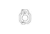
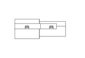
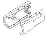
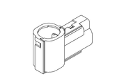
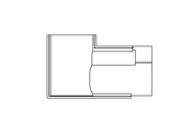
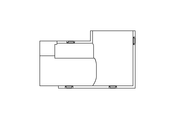
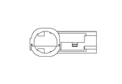
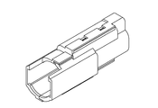
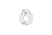
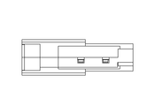
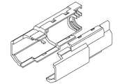
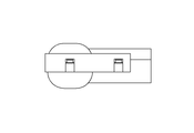
- FIGS Detailed views of the joint cover 10A according to the present embodiment are shown in FIGS.
- the first cover body 12 can accommodate more than half of the outer periphery of the joint 16A because the side surface 15 is formed at a height that covers the side portion of the joint 16A. Thereby, the first cover body 12 can hold the joint 16A more stably when the first cover body 12 is attached to the joint 16A. Therefore, the joint cover 10A can improve workability when the joint cover 10A is attached to the joint 16A.
- the second holding part 28 can hold the upper part of the corrugated tube 22 more reliably by arranging the convex part 23 inside the wall part 26 of the first holding part 24. Therefore, since the joint cover 10A can hold the corrugated tube 22 more reliably only by fixing the second cover body 14 to the first cover body 12, it is possible to improve workability when the joint cover 10A is attached to the joint 16A. Can do.
- the housing wall 31 is formed such that the length from the bottom 29 to the upper end of the housing wall 31 is longer than the outer diameter of the heater wire, so that the heater wire can be more reliably accommodated. Therefore, since the joint cover 10A can prevent the heater wire from being caught when the joint cover 10A is attached to the joint 16A, the workability can be further improved.
- the first cover body 12 and the second cover body 14 have an asymmetric shape because the division position is shifted from the center in the direction of the second cover body 14. Accordingly, the joint cover 10A can prevent the first cover body 12 and the second cover body 14 from being mistaken when mounted on the joint 16A, so that the work order can be unified and the workability can be improved. Can be improved.
- the joint cover 10A is formed so that the operation part 18 provided in the first terminal part 30 is exposed, so that the operation part 18 is operated with the joint 16A being mounted, and the pipe is connected to the first terminal. It can be attached to and detached from the part 30. Therefore, the joint cover 10A can improve the connection workability of piping.
- the joint cover 10A of the first embodiment has been described with respect to the case where the first terminal portion 30 and the second terminal portion 32 are applied to the joint 16A provided coaxially.
- the present invention may be applied to a so-called elbow joint 16B in which the central axis of the first terminal portion 30 and the central axis of the second terminal portion 32 are orthogonal to each other.
- the first cover body 34 and the second cover body 36 are formed in an elbow shape in accordance with the shape of the joint 16B.
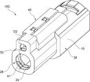
- the 7 includes a first cover body 38 and a second cover body 40.
- the joint cover 10 ⁇ / b> C is formed by the first cover body 38 and the second cover body 40 so as to be divided into two in the left-right direction in the drawing.
- the division position D2 between the first cover body 38 and the second cover body 40 is formed at a position biased toward the second cover body 40 side.
- the first outer peripheral holding portion 42 provided in the first cover body 38 has a first outer peripheral wall portion 45 formed on one side with the central axis in between.
- the first outer peripheral wall portion 45 has a height substantially the same as the radius of the outer diameter of the first terminal portion 50 and is formed integrally with the side surface 15.
- a first notch portion 44 from which the side surface 15 is removed is formed on the other side of the central axis of the first outer periphery holding portion 42.
- the second outer peripheral holding part 46 provided in the second cover body 40 has a second outer peripheral wall part 47 formed on one side with the central axis in between.
- the second outer peripheral wall portion 47 has a height that is substantially the same as the radius of the outer diameter of the first terminal portion 50.
- a second notch 48 is formed on the other side across the central axis of the second outer periphery holding portion 46.
- the joint 16C includes a first terminal portion 50 and a second terminal portion 52 formed coaxially with the first terminal portion 50.
- the first terminal portion 50 is provided with an operation portion 54 on the other side across the central axis.
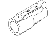
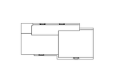
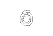
- FIGS. 1-10 Detailed views of the joint cover 10C according to the present embodiment are shown in FIGS.
- the second cover body 40 is disposed so as to close the opening of the first cover body 38, and the second cover body 40 is fixed to the first cover body 38.
- An outer periphery holding part is formed. That is, the outer periphery holding part is formed by the first outer periphery holding part 42 and the second outer periphery holding part 46.
- the outer peripheral holding part covers one side of the first terminal part 50 with the first outer peripheral wall part 45 and the second outer peripheral wall part 47 sandwiching the central axis.
- the division position on one side of the first terminal portion 50 is formed at the approximate center of the outer periphery of the joint 16C.
- an operation window is formed by the first cutout portion 44 and the second cutout portion 48 on the other side of the outer periphery holding portion. The operation portion 54 of the joint 16C is exposed through the operation window.
- the joint cover 10C according to the present embodiment is formed at a height at which the side surface 15 of the first cover body 38 covers the side portion of the joint 16C, the same effect as in the first embodiment. Can be obtained.
- the first outer peripheral wall portion 45 and the second outer peripheral wall portion 47 are formed so as to have substantially the same length as the radius of the outer diameter of the first terminal portion 50.
- the division position on one side of the one terminal portion 50 is formed at the approximate center of the outer periphery of the joint 16C. Therefore, the joint cover 10 ⁇ / b> C can reduce the size of the portion covering the first terminal portion 50.
- the joint cover 10C of the second embodiment has been described with respect to the case where the first terminal portion 50 and the second terminal portion 52 are applied to the joint 16C provided on the same axis.
- the present invention may be applied to a so-called elbow joint 16D in which the central axis of the first terminal portion 50 and the central axis of the second terminal portion 52 are orthogonal to each other.
- the first cover body 56 and the second cover body 58 are formed in an elbow shape in accordance with the shape of the joint 16D.
- the present invention is not limited to the above-described embodiment, and can be appropriately changed within the scope of the gist of the present invention.
Landscapes
- Engineering & Computer Science (AREA)
- General Engineering & Computer Science (AREA)
- Chemical & Material Sciences (AREA)
- Mechanical Engineering (AREA)
- Biomedical Technology (AREA)
- Health & Medical Sciences (AREA)
- Combustion & Propulsion (AREA)
- Environmental & Geological Engineering (AREA)
- Analytical Chemistry (AREA)
- General Chemical & Material Sciences (AREA)
- Oil, Petroleum & Natural Gas (AREA)
- Chemical Kinetics & Catalysis (AREA)
- Protection Of Pipes Against Damage, Friction, And Corrosion (AREA)
- Connector Housings Or Holding Contact Members (AREA)
- Exhaust Gas After Treatment (AREA)
Abstract
Description
(1)全体構成
図1に示す継手カバー10Aは、第1カバー体12と第2カバー体14とを備え、継手16Aの外側に設けられる。継手16Aには、管体として尿素水供給用配管20が接続されている。尿素水供給用配管20は、保護チューブとしてのコルゲートチューブ22内に挿入されている。
上記のように第1カバー体12は、側面15が継手16Aの側部を覆う高さに形成されていることにより、継手16Aの外周の半分超を収容し得る。これにより第1カバー体12は、継手16Aに第1カバー体12を装着する際、継手16Aをより安定して保持することができる。したがって、継手カバー10Aは、継手16Aに装着する際の作業性を向上することができる。
上記第1実施形態の継手カバー10Aは、第1端子部30と第2端子部32とが同軸上に設けられた継手16Aに適用する場合について説明したが、本発明はこれに限らない。例えば、図6に示すように、第1端子部30の中心軸と第2端子部32の中心軸とが直交するように配置された、いわゆるエルボ型の継手16Bに適用してもよい。この場合、継手カバー10Bは、継手16Bの形状に合わせて、第1カバー体34と第2カバー体36とがエルボ型に形成されている。本変形例に係る継手カバー10Bの詳細図を図18~図25に示す。
(1)全体構成
次に、本発明の第2実施形態に係る継手カバー10Cについて説明する。本実施形態に係る継手カバー10Cは、外周保持部の構成が、上記第1実施形態と異なる。上記第1実施形態と同様の構成については同様の符号を付し、説明を省略する。
本実施形態に係る継手カバー10Cは、第1カバー体38の側面15が継手16Cの側部を覆う高さに形成されているので、上記第1実施形態と同様の効果を得ることができる。
上記第2実施形態の継手カバー10Cは、第1端子部50と第2端子部52とが同軸上に設けられた継手16Cに適用する場合について説明したが、本発明はこれに限らない。例えば、図9に示すように、第1端子部50の中心軸と第2端子部52の中心軸とが直交するように配置された、いわゆるエルボ型の継手16Dに適用してもよい。この場合、継手カバー10Dは、継手16Dの形状に合わせて、第1カバー体56と第2カバー体58とがエルボ型に形成されている。本変形例に係る継手カバー10Dの詳細図を図34~図41に示す。
本発明は上記実施形態に限定されるものではなく、本発明の趣旨の範囲内で適宜変更することが可能である。
12 第1カバー体
14 第2カバー体
16A、16B、16C、16D 継手
20 尿素水供給用配管(管体)
22 コルゲートチューブ(保護チューブ)
23 凸部
24 第1保持部
28 第2保持部
30 第1端子部(端子部)
32 第2端子部(端子部)
41 保持部
D1 分割位置
Claims (5)
- 継手の外側に設けられる継手カバーにおいて、
開口を有し、前記継手の一側を収容する第1カバー体と、
前記第1カバー体に着脱可能な第2カバー体と
を備え、
前記第1カバー体と前記第2カバー体が接触して形成される分割位置が、前記第2カバー体側に偏った位置に形成されることを特徴とする継手カバー。 - 前記継手に接続される管体が挿入される、保護チューブの外周を保持する保持部を備え、
前記保持部は、
前記第1カバー体に形成された第1保持部と
前記第2カバー体に形成された第2保持部と
からなり、
前記第2保持部は、前記保護チューブの外周に接触する凸部を有し、
前記凸部は、前記第1保持部の内側に配置される
ことを特徴とする請求項1記載の継手カバー。 - 前記継手に形成された端子部を覆う部分において、前記分割位置が、前記継手の外周の略中央に形成されることを特徴とする請求項1又は2記載の継手カバー。
- 前記継手の端子部に対応する位置に、操作窓が形成されていることを特徴とする請求項1~3のいずれか1項記載の継手カバー。
- 前記継手の端子部の外周が露出し得るように形成されていることを特徴とする請求項1又は2記載の継手カバー。
Priority Applications (4)
| Application Number | Priority Date | Filing Date | Title |
|---|---|---|---|
| DE112014006048.8T DE112014006048T5 (de) | 2013-12-25 | 2014-12-18 | Verbinderabdeckung |
| JP2015554798A JPWO2015098684A1 (ja) | 2013-12-25 | 2014-12-18 | 継手カバー |
| CN201480067420.XA CN105849455B (zh) | 2013-12-25 | 2014-12-18 | 接头盖 |
| US15/106,376 US10047895B2 (en) | 2013-12-25 | 2014-12-18 | Joint cover |
Applications Claiming Priority (2)
| Application Number | Priority Date | Filing Date | Title |
|---|---|---|---|
| JP2013267599 | 2013-12-25 | ||
| JP2013-267599 | 2013-12-25 |
Publications (1)
| Publication Number | Publication Date |
|---|---|
| WO2015098684A1 true WO2015098684A1 (ja) | 2015-07-02 |
Family
ID=53478545
Family Applications (1)
| Application Number | Title | Priority Date | Filing Date |
|---|---|---|---|
| PCT/JP2014/083531 Ceased WO2015098684A1 (ja) | 2013-12-25 | 2014-12-18 | 継手カバー |
Country Status (5)
| Country | Link |
|---|---|
| US (1) | US10047895B2 (ja) |
| JP (1) | JPWO2015098684A1 (ja) |
| CN (1) | CN105849455B (ja) |
| DE (1) | DE112014006048T5 (ja) |
| WO (1) | WO2015098684A1 (ja) |
Families Citing this family (2)
| Publication number | Priority date | Publication date | Assignee | Title |
|---|---|---|---|---|
| CA2979484C (en) * | 2017-07-10 | 2025-09-16 | Bombardier Recreational Products Inc. | VEHICLE ACCESSORY CONNECTOR SLEEVE, SLEEVE AND CLIP ASSEMBLY, AND VEHICLE ACCESSORY INSTALLATION KIT |
| IT201900022182A1 (it) * | 2019-11-26 | 2021-05-26 | Pietro Fiorentini Spa | Dispositivo da applicare in corrispondenza di un passaggio del gas. |
Citations (11)
| Publication number | Priority date | Publication date | Assignee | Title |
|---|---|---|---|---|
| JP2001200983A (ja) * | 2000-01-18 | 2001-07-27 | Mirai Ind Co Ltd | 流体管配管経路の壁引出屈曲部に使用される管類保護カバー、及び当該屈曲部における配管方法 |
| JP2007078064A (ja) * | 2005-09-14 | 2007-03-29 | Mirai Ind Co Ltd | 配線配管ダクト付属品及び配線配管ダクト装置 |
| JP2009168120A (ja) * | 2008-01-15 | 2009-07-30 | Nitta Moore Co | 管継手の加熱・保温カバー |
| JP2009168119A (ja) * | 2008-01-15 | 2009-07-30 | Nitta Moore Co | 管継手の加熱・保温カバー |
| JP2009264402A (ja) * | 2008-04-22 | 2009-11-12 | Mirai Ind Co Ltd | T字分岐配管構造、分岐保護カバー及び迂回分岐継手 |
| JP2010065735A (ja) * | 2008-09-09 | 2010-03-25 | Mirai Ind Co Ltd | 配線・配管保護部材 |
| JP2010133516A (ja) * | 2008-12-05 | 2010-06-17 | Mirai Ind Co Ltd | 給水湯管引出し口形成具 |
| US20100290764A1 (en) * | 2007-04-26 | 2010-11-18 | Olav Borgmeier | Line connector for media lines |
| JP2011506889A (ja) * | 2007-12-21 | 2011-03-03 | フォス・アウトモーティヴ・ゲー・エム・ベー・ハー | 加熱式媒体導管ユニット |
| JP2013108533A (ja) * | 2011-11-18 | 2013-06-06 | Mirai Ind Co Ltd | 管継手収容カバー、及び配管方法 |
| JP2014009755A (ja) * | 2012-06-29 | 2014-01-20 | Togo Seisakusho Corp | コネクタカバー |
Family Cites Families (19)
| Publication number | Priority date | Publication date | Assignee | Title |
|---|---|---|---|---|
| FR2622956B1 (fr) * | 1987-11-06 | 1990-06-29 | Planet Wattohm Sa | Profile en deux parties emboitables,en particulier goulotte a corps et couvercle |
| GB9207388D0 (en) * | 1992-04-03 | 1992-05-13 | Jordan Leslie E | Clamps for use with well tubulars |
| JP4092086B2 (ja) * | 2000-06-30 | 2008-05-28 | 矢崎総業株式会社 | コルゲートチューブ固定具 |
| US6619697B2 (en) * | 2000-12-27 | 2003-09-16 | Nkf Kabel B.V. | Y-branch splittable connector |
| US6968864B2 (en) * | 2001-11-14 | 2005-11-29 | Yazaki Corporation | Rotary holder for corrugated tube |
| US7007900B2 (en) * | 2002-10-01 | 2006-03-07 | Andrew Corporation | Cable hanger |
| US6916051B2 (en) * | 2003-02-13 | 2005-07-12 | Medical Components, Inc. | Coupler for a flexible tube |
| JP2005057968A (ja) * | 2003-08-07 | 2005-03-03 | Yazaki Corp | ハーネス固定用プロテクタ |
| DE102008022492B4 (de) * | 2007-05-07 | 2011-09-22 | Sumitomo Wiring Systems, Ltd. | Schutzvorrichtung |
| JP4930177B2 (ja) * | 2007-05-07 | 2012-05-16 | 住友電装株式会社 | プロテクタ |
| US7692095B2 (en) * | 2007-08-21 | 2010-04-06 | Yazaki Corporation | Wire harness lead-out structure of protector |
| JP5326461B2 (ja) | 2008-09-22 | 2013-10-30 | マツダ株式会社 | エンジンの排気浄化装置 |
| US8944474B2 (en) * | 2008-12-25 | 2015-02-03 | Yazaki Corporation | Holder |
| DE202009012230U1 (de) * | 2009-06-23 | 2010-11-04 | Voss Automotive Gmbh | Elektrisch beheizbare Medienleitung sowie Leitungsverbinder |
| TWM397127U (en) * | 2010-06-24 | 2011-01-21 | Gemtek Technology Co Ltd | Detachable fastening mechanism |
| DE102010035028B4 (de) * | 2010-08-20 | 2013-07-18 | Voss Automotive Gmbh | Beheizbare Leitungsverbinder mit Isolations- und/oder Schutzabdeckung und beheizbare Medienleitung mit zumindest einem Leitungsverbinder mit Isolations- und/oder Schutzabdeckung |
| JP5353908B2 (ja) * | 2011-01-21 | 2013-11-27 | 住友電装株式会社 | ワイヤハーネス用プロテクタ |
| CN202167800U (zh) | 2011-06-30 | 2012-03-14 | 长城汽车股份有限公司 | 汽车发动机护线盒 |
| CN102537588A (zh) * | 2012-02-06 | 2012-07-04 | 汪仕斌 | 防缩径管件专用保护套 |
-
2014
- 2014-12-18 JP JP2015554798A patent/JPWO2015098684A1/ja active Pending
- 2014-12-18 DE DE112014006048.8T patent/DE112014006048T5/de not_active Withdrawn
- 2014-12-18 CN CN201480067420.XA patent/CN105849455B/zh active Active
- 2014-12-18 WO PCT/JP2014/083531 patent/WO2015098684A1/ja not_active Ceased
- 2014-12-18 US US15/106,376 patent/US10047895B2/en active Active
Patent Citations (11)
| Publication number | Priority date | Publication date | Assignee | Title |
|---|---|---|---|---|
| JP2001200983A (ja) * | 2000-01-18 | 2001-07-27 | Mirai Ind Co Ltd | 流体管配管経路の壁引出屈曲部に使用される管類保護カバー、及び当該屈曲部における配管方法 |
| JP2007078064A (ja) * | 2005-09-14 | 2007-03-29 | Mirai Ind Co Ltd | 配線配管ダクト付属品及び配線配管ダクト装置 |
| US20100290764A1 (en) * | 2007-04-26 | 2010-11-18 | Olav Borgmeier | Line connector for media lines |
| JP2011506889A (ja) * | 2007-12-21 | 2011-03-03 | フォス・アウトモーティヴ・ゲー・エム・ベー・ハー | 加熱式媒体導管ユニット |
| JP2009168120A (ja) * | 2008-01-15 | 2009-07-30 | Nitta Moore Co | 管継手の加熱・保温カバー |
| JP2009168119A (ja) * | 2008-01-15 | 2009-07-30 | Nitta Moore Co | 管継手の加熱・保温カバー |
| JP2009264402A (ja) * | 2008-04-22 | 2009-11-12 | Mirai Ind Co Ltd | T字分岐配管構造、分岐保護カバー及び迂回分岐継手 |
| JP2010065735A (ja) * | 2008-09-09 | 2010-03-25 | Mirai Ind Co Ltd | 配線・配管保護部材 |
| JP2010133516A (ja) * | 2008-12-05 | 2010-06-17 | Mirai Ind Co Ltd | 給水湯管引出し口形成具 |
| JP2013108533A (ja) * | 2011-11-18 | 2013-06-06 | Mirai Ind Co Ltd | 管継手収容カバー、及び配管方法 |
| JP2014009755A (ja) * | 2012-06-29 | 2014-01-20 | Togo Seisakusho Corp | コネクタカバー |
Also Published As
| Publication number | Publication date |
|---|---|
| JPWO2015098684A1 (ja) | 2017-03-23 |
| DE112014006048T5 (de) | 2016-09-08 |
| CN105849455B (zh) | 2018-11-06 |
| US10047895B2 (en) | 2018-08-14 |
| US20170030507A1 (en) | 2017-02-02 |
| CN105849455A (zh) | 2016-08-10 |
Similar Documents
| Publication | Publication Date | Title |
|---|---|---|
| JP4823980B2 (ja) | 加熱・保温チューブを有する装置 | |
| US10851932B2 (en) | Connection unit | |
| JP5898013B2 (ja) | 電線保護部材 | |
| JP5441880B2 (ja) | 制御弁用フィルタ装置 | |
| JP2013070553A (ja) | ケーブル・配管類保護案内部材用取り付けブラケット | |
| JP2018082528A (ja) | 防水部材 | |
| WO2015098684A1 (ja) | 継手カバー | |
| CN103392056B (zh) | 排气净化装置 | |
| JP2013239419A (ja) | ワイヤーハーネス及び管状保護部材 | |
| CN105829674B (zh) | 催化转化器 | |
| CN108367221A (zh) | 适于被锁定为弯曲形状的具有平坦形状的过滤器元件 | |
| JP2005061254A (ja) | 燃料タンク用ストレーナ装置 | |
| JP2019212751A (ja) | 抵抗素子収納用ケース及び抵抗器 | |
| US9553440B2 (en) | Wire seal assembly | |
| KR200418219Y1 (ko) | 자동차의 케이블 연결구 커버장치 | |
| WO2016067877A1 (ja) | ワイヤーハーネスモジュール | |
| TWI692372B (zh) | 鑰部結構以及具有前述鑰部結構之過濾裝置 | |
| KR101675461B1 (ko) | 농기계용 엔진 배기가스 복합정화장치 | |
| CN109357092B (zh) | 一种气电管路的接头 | |
| JP2011127717A (ja) | 管継手 | |
| JP2013096435A (ja) | ダクト継手 | |
| JP2019148220A (ja) | 排気浄化装置 | |
| JP4189245B2 (ja) | 配線引き込み部の防水構造 | |
| JPH04224394A (ja) | 配管用コネクタ | |
| JP5491570B2 (ja) | 磁界処理装置 |
Legal Events
| Date | Code | Title | Description |
|---|---|---|---|
| 121 | Ep: the epo has been informed by wipo that ep was designated in this application |
Ref document number: 14875873 Country of ref document: EP Kind code of ref document: A1 |
|
| ENP | Entry into the national phase |
Ref document number: 2015554798 Country of ref document: JP Kind code of ref document: A |
|
| WWE | Wipo information: entry into national phase |
Ref document number: 15106376 Country of ref document: US |
|
| WWE | Wipo information: entry into national phase |
Ref document number: 112014006048 Country of ref document: DE |
|
| 122 | Ep: pct application non-entry in european phase |
Ref document number: 14875873 Country of ref document: EP Kind code of ref document: A1 |