WO2015098239A1 - Dispositif de vanne - Google Patents
Dispositif de vanne Download PDFInfo
- Publication number
- WO2015098239A1 WO2015098239A1 PCT/JP2014/077136 JP2014077136W WO2015098239A1 WO 2015098239 A1 WO2015098239 A1 WO 2015098239A1 JP 2014077136 W JP2014077136 W JP 2014077136W WO 2015098239 A1 WO2015098239 A1 WO 2015098239A1
- Authority
- WO
- WIPO (PCT)
- Prior art keywords
- diaphragm
- valve
- port
- outflow port
- valve seat
- Prior art date
Links
- 239000012530 fluid Substances 0.000 claims abstract description 27
- 239000013013 elastic material Substances 0.000 claims abstract description 15
- 229920001971 elastomer Polymers 0.000 claims description 16
- 239000000945 filler Substances 0.000 claims description 7
- VTYYLEPIZMXCLO-UHFFFAOYSA-L Calcium carbonate Chemical compound [Ca+2].[O-]C([O-])=O VTYYLEPIZMXCLO-UHFFFAOYSA-L 0.000 claims description 6
- VYPSYNLAJGMNEJ-UHFFFAOYSA-N Silicium dioxide Chemical compound O=[Si]=O VYPSYNLAJGMNEJ-UHFFFAOYSA-N 0.000 claims description 6
- TZCXTZWJZNENPQ-UHFFFAOYSA-L barium sulfate Chemical compound [Ba+2].[O-]S([O-])(=O)=O TZCXTZWJZNENPQ-UHFFFAOYSA-L 0.000 claims description 6
- YCKRFDGAMUMZLT-UHFFFAOYSA-N Fluorine atom Chemical compound [F] YCKRFDGAMUMZLT-UHFFFAOYSA-N 0.000 claims description 3
- 229920000459 Nitrile rubber Polymers 0.000 claims description 3
- 229910000019 calcium carbonate Inorganic materials 0.000 claims description 3
- 239000006229 carbon black Substances 0.000 claims description 3
- 239000011737 fluorine Substances 0.000 claims description 3
- 229910052731 fluorine Inorganic materials 0.000 claims description 3
- 239000000377 silicon dioxide Substances 0.000 claims description 3
- 229920002379 silicone rubber Polymers 0.000 claims description 3
- 239000004945 silicone rubber Substances 0.000 claims description 3
- 239000000454 talc Substances 0.000 claims description 3
- 229910052623 talc Inorganic materials 0.000 claims description 3
- 125000000383 tetramethylene group Chemical group [H]C([H])([*:1])C([H])([H])C([H])([H])C([H])([H])[*:2] 0.000 claims description 3
- 238000003825 pressing Methods 0.000 abstract description 5
- 238000007789 sealing Methods 0.000 description 22
- XEEYBQQBJWHFJM-UHFFFAOYSA-N Iron Chemical group [Fe] XEEYBQQBJWHFJM-UHFFFAOYSA-N 0.000 description 7
- 239000000463 material Substances 0.000 description 7
- 239000012528 membrane Substances 0.000 description 6
- 210000002445 nipple Anatomy 0.000 description 6
- 230000002093 peripheral effect Effects 0.000 description 6
- 238000005192 partition Methods 0.000 description 5
- 230000013011 mating Effects 0.000 description 4
- 238000005259 measurement Methods 0.000 description 3
- 239000011347 resin Substances 0.000 description 3
- 229920005989 resin Polymers 0.000 description 3
- 239000000126 substance Substances 0.000 description 3
- 238000004891 communication Methods 0.000 description 2
- 230000000694 effects Effects 0.000 description 2
- 230000007774 longterm Effects 0.000 description 2
- 229920000642 polymer Polymers 0.000 description 2
- 229920002943 EPDM rubber Polymers 0.000 description 1
- 229920006169 Perfluoroelastomer Polymers 0.000 description 1
- 230000001133 acceleration Effects 0.000 description 1
- 230000004888 barrier function Effects 0.000 description 1
- 238000005452 bending Methods 0.000 description 1
- 239000003153 chemical reaction reagent Substances 0.000 description 1
- 230000000052 comparative effect Effects 0.000 description 1
- 238000004132 cross linking Methods 0.000 description 1
- 230000005489 elastic deformation Effects 0.000 description 1
- 230000005611 electricity Effects 0.000 description 1
- 238000003891 environmental analysis Methods 0.000 description 1
- 230000005484 gravity Effects 0.000 description 1
- 239000011256 inorganic filler Substances 0.000 description 1
- 229910003475 inorganic filler Inorganic materials 0.000 description 1
- 238000007689 inspection Methods 0.000 description 1
- 229910052742 iron Inorganic materials 0.000 description 1
- 238000004519 manufacturing process Methods 0.000 description 1
- 239000007769 metal material Substances 0.000 description 1
- 238000000465 moulding Methods 0.000 description 1
- 238000011160 research Methods 0.000 description 1
- 238000009751 slip forming Methods 0.000 description 1
- 238000010998 test method Methods 0.000 description 1
Images


Classifications
-
- F—MECHANICAL ENGINEERING; LIGHTING; HEATING; WEAPONS; BLASTING
- F16—ENGINEERING ELEMENTS AND UNITS; GENERAL MEASURES FOR PRODUCING AND MAINTAINING EFFECTIVE FUNCTIONING OF MACHINES OR INSTALLATIONS; THERMAL INSULATION IN GENERAL
- F16K—VALVES; TAPS; COCKS; ACTUATING-FLOATS; DEVICES FOR VENTING OR AERATING
- F16K11/00—Multiple-way valves, e.g. mixing valves; Pipe fittings incorporating such valves
- F16K11/02—Multiple-way valves, e.g. mixing valves; Pipe fittings incorporating such valves with all movable sealing faces moving as one unit
- F16K11/04—Multiple-way valves, e.g. mixing valves; Pipe fittings incorporating such valves with all movable sealing faces moving as one unit comprising only lift valves
- F16K11/052—Multiple-way valves, e.g. mixing valves; Pipe fittings incorporating such valves with all movable sealing faces moving as one unit comprising only lift valves with pivoted closure members, e.g. butterfly valves
- F16K11/0525—Multiple-way valves, e.g. mixing valves; Pipe fittings incorporating such valves with all movable sealing faces moving as one unit comprising only lift valves with pivoted closure members, e.g. butterfly valves the closure members being pivoted around an essentially central axis
-
- B—PERFORMING OPERATIONS; TRANSPORTING
- B01—PHYSICAL OR CHEMICAL PROCESSES OR APPARATUS IN GENERAL
- B01L—CHEMICAL OR PHYSICAL LABORATORY APPARATUS FOR GENERAL USE
- B01L3/00—Containers or dishes for laboratory use, e.g. laboratory glassware; Droppers
- B01L3/56—Labware specially adapted for transferring fluids
- B01L3/567—Valves, taps or stop-cocks
-
- F—MECHANICAL ENGINEERING; LIGHTING; HEATING; WEAPONS; BLASTING
- F16—ENGINEERING ELEMENTS AND UNITS; GENERAL MEASURES FOR PRODUCING AND MAINTAINING EFFECTIVE FUNCTIONING OF MACHINES OR INSTALLATIONS; THERMAL INSULATION IN GENERAL
- F16K—VALVES; TAPS; COCKS; ACTUATING-FLOATS; DEVICES FOR VENTING OR AERATING
- F16K11/00—Multiple-way valves, e.g. mixing valves; Pipe fittings incorporating such valves
- F16K11/02—Multiple-way valves, e.g. mixing valves; Pipe fittings incorporating such valves with all movable sealing faces moving as one unit
- F16K11/022—Multiple-way valves, e.g. mixing valves; Pipe fittings incorporating such valves with all movable sealing faces moving as one unit comprising a deformable member
-
- F—MECHANICAL ENGINEERING; LIGHTING; HEATING; WEAPONS; BLASTING
- F16—ENGINEERING ELEMENTS AND UNITS; GENERAL MEASURES FOR PRODUCING AND MAINTAINING EFFECTIVE FUNCTIONING OF MACHINES OR INSTALLATIONS; THERMAL INSULATION IN GENERAL
- F16K—VALVES; TAPS; COCKS; ACTUATING-FLOATS; DEVICES FOR VENTING OR AERATING
- F16K11/00—Multiple-way valves, e.g. mixing valves; Pipe fittings incorporating such valves
- F16K11/02—Multiple-way valves, e.g. mixing valves; Pipe fittings incorporating such valves with all movable sealing faces moving as one unit
- F16K11/04—Multiple-way valves, e.g. mixing valves; Pipe fittings incorporating such valves with all movable sealing faces moving as one unit comprising only lift valves
- F16K11/052—Multiple-way valves, e.g. mixing valves; Pipe fittings incorporating such valves with all movable sealing faces moving as one unit comprising only lift valves with pivoted closure members, e.g. butterfly valves
-
- F—MECHANICAL ENGINEERING; LIGHTING; HEATING; WEAPONS; BLASTING
- F16—ENGINEERING ELEMENTS AND UNITS; GENERAL MEASURES FOR PRODUCING AND MAINTAINING EFFECTIVE FUNCTIONING OF MACHINES OR INSTALLATIONS; THERMAL INSULATION IN GENERAL
- F16K—VALVES; TAPS; COCKS; ACTUATING-FLOATS; DEVICES FOR VENTING OR AERATING
- F16K25/00—Details relating to contact between valve members and seats
- F16K25/005—Particular materials for seats or closure elements
-
- F—MECHANICAL ENGINEERING; LIGHTING; HEATING; WEAPONS; BLASTING
- F16—ENGINEERING ELEMENTS AND UNITS; GENERAL MEASURES FOR PRODUCING AND MAINTAINING EFFECTIVE FUNCTIONING OF MACHINES OR INSTALLATIONS; THERMAL INSULATION IN GENERAL
- F16K—VALVES; TAPS; COCKS; ACTUATING-FLOATS; DEVICES FOR VENTING OR AERATING
- F16K31/00—Actuating devices; Operating means; Releasing devices
- F16K31/02—Actuating devices; Operating means; Releasing devices electric; magnetic
- F16K31/06—Actuating devices; Operating means; Releasing devices electric; magnetic using a magnet, e.g. diaphragm valves, cutting off by means of a liquid
- F16K31/0603—Multiple-way valves
- F16K31/0641—Multiple-way valves the valve member being a diaphragm
-
- F—MECHANICAL ENGINEERING; LIGHTING; HEATING; WEAPONS; BLASTING
- F16—ENGINEERING ELEMENTS AND UNITS; GENERAL MEASURES FOR PRODUCING AND MAINTAINING EFFECTIVE FUNCTIONING OF MACHINES OR INSTALLATIONS; THERMAL INSULATION IN GENERAL
- F16K—VALVES; TAPS; COCKS; ACTUATING-FLOATS; DEVICES FOR VENTING OR AERATING
- F16K31/00—Actuating devices; Operating means; Releasing devices
- F16K31/02—Actuating devices; Operating means; Releasing devices electric; magnetic
- F16K31/06—Actuating devices; Operating means; Releasing devices electric; magnetic using a magnet, e.g. diaphragm valves, cutting off by means of a liquid
- F16K31/10—Actuating devices; Operating means; Releasing devices electric; magnetic using a magnet, e.g. diaphragm valves, cutting off by means of a liquid with additional mechanism between armature and closure member
- F16K31/105—Actuating devices; Operating means; Releasing devices electric; magnetic using a magnet, e.g. diaphragm valves, cutting off by means of a liquid with additional mechanism between armature and closure member for rotating valves
-
- F—MECHANICAL ENGINEERING; LIGHTING; HEATING; WEAPONS; BLASTING
- F16—ENGINEERING ELEMENTS AND UNITS; GENERAL MEASURES FOR PRODUCING AND MAINTAINING EFFECTIVE FUNCTIONING OF MACHINES OR INSTALLATIONS; THERMAL INSULATION IN GENERAL
- F16K—VALVES; TAPS; COCKS; ACTUATING-FLOATS; DEVICES FOR VENTING OR AERATING
- F16K7/00—Diaphragm valves or cut-off apparatus, e.g. with a member deformed, but not moved bodily, to close the passage ; Pinch valves
- F16K7/12—Diaphragm valves or cut-off apparatus, e.g. with a member deformed, but not moved bodily, to close the passage ; Pinch valves with flat, dished, or bowl-shaped diaphragm
- F16K7/14—Diaphragm valves or cut-off apparatus, e.g. with a member deformed, but not moved bodily, to close the passage ; Pinch valves with flat, dished, or bowl-shaped diaphragm arranged to be deformed against a flat seat
-
- B—PERFORMING OPERATIONS; TRANSPORTING
- B01—PHYSICAL OR CHEMICAL PROCESSES OR APPARATUS IN GENERAL
- B01L—CHEMICAL OR PHYSICAL LABORATORY APPARATUS FOR GENERAL USE
- B01L2300/00—Additional constructional details
- B01L2300/12—Specific details about materials
- B01L2300/123—Flexible; Elastomeric
-
- B—PERFORMING OPERATIONS; TRANSPORTING
- B01—PHYSICAL OR CHEMICAL PROCESSES OR APPARATUS IN GENERAL
- B01L—CHEMICAL OR PHYSICAL LABORATORY APPARATUS FOR GENERAL USE
- B01L2400/00—Moving or stopping fluids
- B01L2400/06—Valves, specific forms thereof
- B01L2400/0622—Valves, specific forms thereof distribution valves, valves having multiple inlets and/or outlets, e.g. metering valves, multi-way valves
-
- B—PERFORMING OPERATIONS; TRANSPORTING
- B01—PHYSICAL OR CHEMICAL PROCESSES OR APPARATUS IN GENERAL
- B01L—CHEMICAL OR PHYSICAL LABORATORY APPARATUS FOR GENERAL USE
- B01L2400/00—Moving or stopping fluids
- B01L2400/06—Valves, specific forms thereof
- B01L2400/0633—Valves, specific forms thereof with moving parts
- B01L2400/0638—Valves, specific forms thereof with moving parts membrane valves, flap valves
-
- Y—GENERAL TAGGING OF NEW TECHNOLOGICAL DEVELOPMENTS; GENERAL TAGGING OF CROSS-SECTIONAL TECHNOLOGIES SPANNING OVER SEVERAL SECTIONS OF THE IPC; TECHNICAL SUBJECTS COVERED BY FORMER USPC CROSS-REFERENCE ART COLLECTIONS [XRACs] AND DIGESTS
- Y10—TECHNICAL SUBJECTS COVERED BY FORMER USPC
- Y10T—TECHNICAL SUBJECTS COVERED BY FORMER US CLASSIFICATION
- Y10T137/00—Fluid handling
- Y10T137/8593—Systems
- Y10T137/86493—Multi-way valve unit
- Y10T137/86501—Sequential distributor or collector type
Definitions
- the present invention relates to a valve device used in various analytical devices such as a chemical inspection device, an environmental analysis device, or a biotechnology research equipment.
- valve device that controls the flow rate of fluid used for measurement.
- a diaphragm made of an elastic rubber material or the like is used as a valve opening / closing mechanism in order to realize excellent chemical resistance and the like.
- the diaphragm forms a partition that partitions the valve chamber, and receives a driving force from the outside to switch the fluid flow path.
- valve device in order to precisely control the flow rate of the fluid, it is necessary to increase the sealing ability of the diaphragm when the port is closed.
- the sealing ability of the diaphragm when the port is closed is improved by increasing the load applied to the diaphragm when the diaphragm is seated on the valve seat formed around the port opening, that is, the pressure on the valve seat of the diaphragm during seating is increased. It is possible to make it.
- Patent Document 1 discloses that in a valve device that drives a diaphragm by a solenoid, a first spring member, a second spring member, and the like, the elastic force (spring force) of the second spring member is the first.
- a valve mechanism is disclosed that is set to approximately twice the spring force of the spring member.
- the present invention has been devised in view of the above circumstances, and its main object is to provide a valve device that can achieve both the sealing ability and the durability of the diaphragm while reducing the size.
- the present invention comprises a valve body that partitions a valve chamber having at least one port through which a fluid flows, a valve body that opens and closes the port, and a drive unit that drives the valve body to open and close the port,
- the port has an opening in which a valve seat is formed, the valve body is arranged so as to cover the valve chamber, and has a diaphragm that opens or closes the port by being seated on or separated from the valve seat.
- the diaphragm is made of an elastic material having a durometer A hardness of A50 to A85 according to JIS-K6253, and a pressure applied to the valve seat of the diaphragm during the seating is 0.5 to 1.0 N / mm. characterized in that it is a 2.
- the diaphragm has a durometer A hardness of A60 to A80 according to JIS-K6253.
- the diaphragm includes at least one of ethylene-propylene-diene, fluorine rubber, hydrogenated nitrile rubber, butylene rubber, or silicone rubber as a rubber component.
- the diaphragm preferably contains one or more of calcium carbonate, silica, barium sulfate, talc, or carbon black as a filler.
- the port includes an inflow port through which fluid flows into the valve chamber and an outflow port through which fluid flows out from the valve chamber, and the diaphragm includes the inflow port or the outflow port. It is desirable to open and close at least one of the ports.
- the port includes an inflow port through which fluid flows into the valve chamber, and an outflow port through which fluid flows out from the valve chamber, the outflow port including a first outflow port and It is preferable that two systems of second outflow ports are arranged and the diaphragm opens and closes the first outflow port and the second outflow port.
- the diaphragm alternately opens and closes the first outflow port and the second outflow port, and the diaphragm of the diaphragm seated on the valve seat of the first outflow port
- the difference between the pressure and the pressure of the diaphragm seated on the valve seat of the second outflow port is preferably 0.40 N / mm 2 or less.
- valve body swings by being driven by the driving means to open and close the port.
- valve body is rotatably supported by a shaft member.
- the diaphragm of the valve device of the present invention is made of an elastic material having a durometer A hardness of A50 to A85 according to JIS-K6253, and the pressure on the valve seat of the diaphragm being seated is 0.5 to 1.0 N / mm 2 .
- the diaphragm is appropriately deformed with respect to the valve seat, and a sufficient sealing ability is obtained. Furthermore, since it is not necessary to press the diaphragm with an excessively large load, the driving means can be reduced in size.
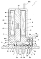
- FIG. 1 is a cross-sectional view of the valve device 1 of the present embodiment.
- the valve device 1 of the present embodiment includes a port through which a fluid flows, a valve body 2 that partitions a valve chamber, a valve body 3 that opens and closes the port, and a valve body 3 that drives the valve body 3.
- the valve body 2 includes a flow path block 20 and a sub block 5.
- the flow path block 20 is formed of, for example, a resin material, and includes a recess 22 that forms a valve chamber 21 that is a space through which fluid flows, an inflow port 23 (Common port) that communicates with the valve chamber 21, and an NC (Normally Close) outflow It has a port 24 (first outlet port), a NO (Normally Open) outlet port 25 (second outlet port), and a holding surface 26 that holds the valve body 3.
- the inflow port 23 is always open, and fluid is supplied from the inflow port 23 into the valve chamber 21.
- the NC outflow port 24 is closed and the NO outflow port 25 is opened, and the fluid flowing into the valve chamber 21 from the inflow port 23 flows along the arrow A and flows out from the NO outflow port 25.
- the flow path block 20 is formed of, for example, a resin material, and includes a recess 22 that forms a valve chamber 21 that is a space through which fluid flows, an inflow port 23
- the valve body 3 includes a diaphragm 6 disposed so as to cover the valve chamber 21, and a swing member 7 provided so as to be swingable with respect to the valve body 2.
- the diaphragm 6 is made of, for example, a rubber material.
- the diaphragm 6 is mounted on the valve body 2 so as to cover the recess 22, thereby forming a valve chamber 21 between the diaphragm 6 and the diaphragm 6.
- the diaphragm 6 has an outer peripheral portion 6a that extends outward.
- the swing member 7 is integrated with the diaphragm 6.
- the swing member 7 has a shaft member 71 that rotatably supports the swing member 7.
- the swing member 7 is made of, for example, a resin material and is disposed above the inflow port 23.
- the shaft member 71 is made of, for example, a metal material.
- the shaft member 71 is provided above the inflow port 23 so as to be substantially orthogonal to the inflow port 23, and both ends thereof are supported by the sub block 5.
- the driving means 4 includes a valve driving unit 40 that drives the swing member 7 and a frame 8 that supports the valve driving unit 40.
- the driving means 4 presses the swing member 7 to seat or separate the diaphragm 6 on the valve seat of the NC outflow port 24 or the NO outflow port 25 to open and close the port.
- the valve device 1 according to the present embodiment is a so-called electromagnetic valve that opens and closes a port by driving the diaphragm 6 by electromagnetic force generated by the driving means 4.
- the sub-block 5 is made of, for example, a resin material, and includes a housing portion 51 that houses the swing member 7 and the like, and a pressing portion 52 that presses the diaphragm 6 against the holding surface 26.
- the sub block 5 is attached to the mating surface 27 in which the recess 22 of the flow path block 20 is formed, and is fixed to the flow path block 20 with a screw (not shown) or the like.
- the outer peripheral portion 6 a of the diaphragm 6 is in close contact with the flow path block 20 by being sandwiched and held and restrained by the holding surface 26 of the flow path block 20 and the pressing portion 52 of the sub block 5. As a result, the valve chamber 21 is sealed, and fluid leakage to the outside of the flow path block 20 is prevented.
- a frame 8 is provided above the sub-block 5.
- the frame 8 accommodates the valve drive unit 40.
- the valve drive unit 40 includes a first plunger (movable iron core) 41, a second plunger 42, a first coil spring 43, a second coil spring 44, a solenoid coil 45, and a fixed iron core 46.
- the first plunger 41 is disposed above the NC outflow port 24.
- the first plunger 41 is inserted into a coil bobbin 47 around which the solenoid coil 45 is wound.
- the fixed iron core 46 is formed with a recess 46 a in which the first coil spring 43 is loaded.
- One end of the first coil spring 43 is in contact with the bottom of the recess 46 a of the fixed iron core 46, and the other end is in contact with the top surface of the first plunger 41.
- the first coil spring 43 pushes down the first plunger 41 toward the first abutting portion 7 a of the swing member 7, and accordingly, the tip 41 b of the first plunger 41 is moved to the first contact portion 7 a of the swing member 7. 1
- the contact part 7a is pressed.
- the spring load of the first coil spring 43 is set larger than the spring load of the second coil spring 44.
- the second plunger 42 is disposed above the NO outflow port 25.
- the second plunger 42 is formed with a cylindrical portion 42a into which the second coil spring 44 is inserted, and a bowl-shaped tip portion 42b formed at the edge of the cylindrical portion 42a.
- One end of the second coil spring 44 is in contact with the tip end portion 42 b of the second plunger 42, and the other end is in contact with the bottom of the recess of the sub block 5.
- the second coil spring 44 pushes down the second plunger 42 toward the second abutting portion 7 b of the swinging member 7, and accordingly, the tip end portion 42 b of the second plunger 42 contacts the swinging member 7.
- the contact portion 7b is pressed.
- the solenoid coil 45 is wound around a cylindrical coil bobbin 47.
- the solenoid coil 45 generates an electromagnetic force when energized.
- a predetermined current flows through the solenoid coil 45 so as to generate an electromagnetic force larger than the difference between the load of the first coil spring 43 and the load of the second coil spring 44.
- a cable 45 a for supplying power to the solenoid coil 45 is drawn into the frame 8.
- the first plunger 41, the first coil spring 43, the solenoid coil 45, the fixed iron core 46 and the coil bobbin 47 are accommodated in the frame 8.
- the solenoid coil 45, the fixed iron core 46 and the coil bobbin 47 are fixed to the frame 8.
- the opening / closing operation of the valve device 1 will be described.
- the elastic force generated by the first coil spring 43 is the elasticity generated by the second coil spring 44. Greater than power. Therefore, in the normal state, the posture of the diaphragm 6 is maintained in a posture rotated counterclockwise in the drawing as shown in FIG. 1, the NC outflow port 24 is closed, and the NO outflow port 25 is opened. Is done. Along with this, as indicated by an arrow A, the fluid flowing into the valve chamber 21 from the inflow port 23 is discharged from the NO outflow port 25.
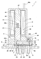
- FIG. 2 shows the valve device 1 in a state where the solenoid coil 45 is energized.
- the first plunger 41 moves in a direction in which the first coil spring 43 is compressed by the electromagnetic force.
- the tip portion 42b of the second plunger 42 presses the second contact portion 7b of the swing member 7, the diaphragm 6 is rotated clockwise, the NO outflow port 25 is closed, and the NC Outflow port 24 is opened.
- the fluid flowing into the valve chamber 21 from the inflow port 23 is discharged from the NC outflow port 24.
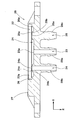
- the flow path block 20 is formed with a recess 22 that partitions the valve chamber 21.
- the recess 22 is formed to be recessed from the mating surface 27 to which the sub-block 5 is joined.
- an NC outflow nipple 29b, an inflow nipple 29a, and an NO outflow nipple 29c are formed to protrude from the back surface opposite to the mating surface 27.
- the inflow port 23 is formed through the inflow nipple 29 a from the recess 22.
- the NC outflow port 24 extends from the recess 22 through the NC outflow nipple 29b, and the NO outflow port 25 extends from the recess 22 through the NO outflow nipple 29c.
- the NC outflow port 24, the inflow port 23, and the NO outflow port 25 are arranged in this order.
- the inflow port 23 has an inflow opening 23 a that opens facing the recess 22.
- the inflow opening 23 a is formed in communication with the valve chamber 21.
- the inflow port 23 allows fluid to flow into the valve chamber 21 from the inflow opening 23a.
- the NC outflow port 24 and the NO outflow port 25 also have outflow openings 24 a and 25 a that open toward the recess 22.
- the outflow openings 24a and 25a are formed in communication with the valve chamber 21, and the NC outflow port 24 and the NO outflow port 25 allow fluid to flow out of the valve chamber 21 through the outflow openings 24a and 25a.
- a first valve seat 24b is provided in the outflow opening 24a of the NC outflow port 24, and a second valve seat 25b is provided in the outflow opening 25a of the NO outflow port 25.
- the 1st valve seat 24b and the 2nd valve seat 25b are formed in the cylinder shape which protrudes in the diaphragm 6 side.
- the NC outflow port 24 or the NO outflow port 25 is closed when the diaphragm 6 comes into close contact with the tip of the first valve seat 24b or the second valve seat 25b in response to the swing of the swing member 7. At this time, the other outflow port is opened, and the fluid flowing into the valve chamber 21 from the inflow port 23 is discharged to the outside of the valve device 1 from the opened outflow port.
- first valve seat 24b and the second valve seat 25b are formed so as to protrude toward the diaphragm 6, the sealing performance between the first valve seat 24b and the second valve seat 25b and the diaphragm 6 when the port is closed is improved. It is done. Thereby, when the NC outflow port 24 or the NO outflow port 25 is closed, the fluid can be prevented from leaking from the valve chamber 21 to the NC outflow port 24 or the NO outflow port 25.
- a first raised portion 24c is formed on the seat surface at the tip of the first valve seat 24b.
- the first raised portion 24c is raised on the diaphragm 6 side.
- the first raised portion 24c is continuously formed in the circumferential direction on the opening side of the NC outflow port 24, that is, on the inner peripheral portion of the first valve seat 24b.
- the first raised portion 24c further improves the sealing performance between the first valve seat 24b and the diaphragm 6 when the NC outflow port 24 is closed, and prevents fluid leakage.
- the first raised portion 25c is provided for the second valve seat 25b of the NO outflow port 25 as well.
- the holding surface 26 is provided on the periphery of the recess 22.
- the holding surface 26 and the mating surface 27 are formed in steps with the side wall 22a of the recess 22 in between.
- a second raised portion 26 a that protrudes toward the diaphragm 6 is formed on the inner peripheral portion of the holding surface 26.
- the second raised portion 26a is formed continuously in the circumferential direction. The second raised portion 26a enhances the sealing property between the holding surface 26 and the outer peripheral portion 6a of the diaphragm 6 and prevents fluid leakage.
- a pair of through holes 28 are formed in the periphery of the recess 22 in a substantially diagonal shape of the main body portion 20a of the flow path block 20.
- the flow path block 20 and the sub-block 5 are fixed by screws that pass through the through holes 28.
- FIG. 5 shows the valve body 3 in which the diaphragm 6 is attached to the swing member 7.
- a through hole 7c into which the shaft member 71 (see FIG. 1) is inserted is provided at the center of the swing member 7.
- the through hole 7c is formed through the swing member 7 in the horizontal direction.
- the through hole 7c is provided between the first contact part 7a and the second contact part 7b, and the distance from the through hole 7c to the first contact part 7a and the through hole 7c to the second contact part 7b. Is equal to the distance to A diaphragm 6 is attached to the lower part of the swing member 7.
- the thinnest film portion 6 b in the diaphragm 6 is provided on the inner side of the outer peripheral portion 6 a of the diaphragm 6, the thinnest film portion 6 b in the diaphragm 6 is provided.
- the film part 6 b is formed over the entire circumference of the diaphragm 6.
- a bottom surface 6c that is seated on the first valve seat 24b or the second valve seat 25b when the port is closed is provided further inside the membrane portion 6b.
- the valve chamber 21 is maintained between the flow path block 20 and the diaphragm 6 by elastically deforming the membrane portion 6 b of the diaphragm 6 following the swing of the swing member 7.
- the hardness of the elastic material constituting the diaphragm 6 is specified in order to achieve both the sealing ability and durability of the diaphragm 6. That is, the durometer A hardness of JIS-K6253 which is an elastic material constituting the diaphragm 6 is preferably A50 or more, more preferably A60 or more, further preferably A65 or more, preferably A85 or less, more preferably. Is A80 or less, more preferably A75 or less.
- the durometer A hardness of the elastic material constituting the diaphragm 6 is less than A50, when the port where the bottom surface 6c of the diaphragm 6 is seated on the first valve seat 24b or the second valve seat 25b is closed, the diaphragm 6 There is a possibility that the deformation of the bottom surface 6 c becomes excessively large, fatigue of the elastic material constituting the diaphragm 6 is accelerated, and the life of the diaphragm 6 is shortened.
- the durometer A hardness of the elastic material constituting the diaphragm 6 exceeds A85, the bottom surface 6c of the diaphragm 6 is difficult to be deformed along the outer shape of the first valve seat 24b or the second valve seat 25b. There is a possibility that the sealing ability cannot be obtained.
- ethylene-propylene-diene EPDM
- fluorine-based rubber FKM, FPM, FFKM
- hydrogenated nitrile rubber HNBR
- butylene-based rubber IIR
- silicone rubber silicone rubber
- the diaphragm 6 is made of an elastic material containing one or more of (VMQ).
- VMQ ethylene-propylene-diene
- the polymer main chain may be broken during long-term use, and the durability performance of the diaphragm 6 may not be maintained.
- ethylene-propylene-diene is particularly preferable from the viewpoints of gas barrier properties, heat resistance, chemical resistance, and production cost.
- the diaphragm 6 is a dynamically used part in which elastic deformation and contact with the first valve seat 24b or the second valve seat 25b are repeated, the diaphragm 6 is gradually worn with use over a long period of time. Therefore, in order to improve the wear resistance of the diaphragm 6, it is desirable to add a filler to the elastic material and adjust the hardness to the above-described range.
- the filler preferably contains one or more inorganic fillers such as calcium carbonate, silica, barium sulfate, and talc, or carbon black.
- the amount of the filler is preferably 10 parts by weight or more, more preferably 20 parts by weight or more, and preferably 80 parts by weight or less, more preferably 70 parts by weight or less.
- the amount of the filler relative to 100 parts by weight of the rubber component is less than 10 parts by weight, the wear resistance is insufficient and the life of the diaphragm 6 is shortened.
- the amount of the filler relative to 100 parts by weight of the rubber component exceeds 80 parts by weight, the bending fatigue resistance of the diaphragm 6 is lowered, and the life of the diaphragm 6 is also shortened.
- the thickness of the membrane 6b of the diaphragm 6 is preferably 0.2 to 1.0 mm.
- the thickness of the membrane portion 6b of the diaphragm 6 is less than 0.2 mm, the membrane portion 6b is broken by long-term use, and the NC outflow port 24 or the NO outflow port 25 is closed. There is a risk of leakage.
- the thickness of the membrane portion 6b of the diaphragm 6 exceeds 1.0 mm, the force required for the swinging of the swinging member 7 increases, and the solenoid coil 45 and the like may be increased in size.
- the pressure for 25b is specified. That is, the pressure on the first valve seat 24b of the diaphragm 6 is preferably 0.5 to 1.0 N / mm 2 .
- the pressure of the diaphragm 6 on the first valve seat 24b or the like is less than 0.5 N / mm 2 , the bottom surface 6c of the diaphragm 6 is not easily deformed along the outer shape of the first valve seat 24b or the like, and a sufficient sealing ability is obtained. May not be obtained.
- the pressure of the diaphragm 6 against the first valve seat 24b and the like exceeds 1.0 N / mm 2 , the deformation of the bottom surface 6c of the diaphragm 6 during the seating becomes excessively large, and fatigue of the elastic material constituting the diaphragm 6 is increased.
- the life of the diaphragm 6 may be shortened due to acceleration.
- the pressure of the diaphragm 6 against the first valve seat 24b is calculated by dividing the force by which the diaphragm 6 pushes the first valve seat 24b by the contact area S1 between the diaphragm 6 and the first valve seat 24b.
- the pressure of the diaphragm 6 against the second valve seat 25b is calculated by dividing the force by which the diaphragm 6 pushes the second valve seat 25b by the contact area S2 between the diaphragm 6 and the second valve seat 25b.
- the difference between the pressure of the diaphragm 6 seated on the first valve seat 24b of the NC outflow port 24 and the pressure of the diaphragm 6 seated on the first valve seat 25b of the NO outflow port 25 is preferably 0.02 N / mm. 2 or more, more preferably 0.04 N / mm 2 or more, preferably 0.40 N / mm 2 or less, and more preferably not more than 0.2 N / mm 2.
- the difference between the pressure applied to the first valve seat 24b of the diaphragm 6 and the pressure applied to the second valve seat 25b is less than 0.02 N / mm 2 , sufficient sealing ability may not be obtained.
- valve drive unit 40 is applied to the diaphragm 6 via the swing member 7 in order to keep the pressure applied to the first valve seat 24b or the second valve seat 25b of the diaphragm 6 being seated within the above range.
- the load to be applied is specified within the following range.
- FIG. 6 shows the main part of the valve device 1 in a state where the NC outflow port 24 is closed by the diaphragm 6.
- the swing member 7 is the first valve of the diaphragm 6.
- the load L1 for pressing the seat 24b side is preferably 2.9N or more, more preferably 3.2N or more, preferably 4.0N or less, more preferably 3.8N or less. In such a state, both the first plunger 41 and the second plunger 42 are in contact with the swing member 7, and the force transmitted to the swing member 7 by the first plunger 41 and the second plunger 42 is canceled out.
- the load L1 that the swing member 7 presses the first valve seat 24b side of the diaphragm 6 is the load L ⁇ 1 by the first coil spring 43 at the length ⁇ 1 and the load L ⁇ 1 by the second coil spring 44 at the length ⁇ 1. It is calculated by the difference between When the load L1 with which the swing member 7 presses the first valve seat 24b side of the diaphragm 6 is less than 2.9N, the bottom surface 6c of the diaphragm 6 is difficult to deform along the outer shape of the first valve seat 24b and the like. There is a risk that sufficient sealing ability may not be obtained.
- the load by the first coil spring 43 is preferably 5.8N to 8.0N, and the load by the second coil spring 44 is 2.9N to 4.0N is desirable.
- the load due to the first coil spring 43 alone is less than 5.8 N and when the load due to the second coil spring 44 alone is less than 2.9 N, the diaphragm 6 is moved along the outer shape of the second valve seat 25 b and the like. The bottom surface 6c is difficult to deform, and there is a possibility that sufficient sealing ability cannot be obtained.
- FIG. 7 shows the main part of the valve device 1 in a state in which the NO outflow port 25 is closed by the diaphragm 6.
- the swinging member 7 is the first member of the diaphragm 6.
- the load L2 for pressing the two-valve seat 25b side is preferably 2.4N or more, more preferably 2.7N or more, preferably 3.5N or less, more preferably 3.3N or less. In this state, since the first plunger 41 is separated from the swing member 7, no force is transmitted to the swing member 7 by the first plunger 41.
- the load L2 with which the swing member 7 presses the second valve seat 25b side of the diaphragm 6 is equal to the load L ⁇ 2 due to the second coil spring 44 and gravity or the like having a length of ⁇ 2.
- the load L2 with which the swing member 7 presses the second valve seat 25b side of the diaphragm 6 is less than 2.4N, the bottom surface 6c of the diaphragm 6 is difficult to deform along the outer shape of the second valve seat 25b and the like. There is a risk that sufficient sealing ability may not be obtained.
- the load by the second coil spring 44 alone is preferably 2.4N to 3.5N. If the load of the second coil spring 44 alone is less than 2.4N, the bottom surface 6c of the diaphragm 6 is difficult to deform along the outer shape of the second valve seat 25b and the like, and there is a possibility that sufficient sealing ability may not be obtained. is there. On the other hand, when the load by the second coil spring 44 alone exceeds 3.5 N, the load by the first coil spring 43 alone needs to be increased further. As a result, similarly to the above, it is difficult to reduce the size of the driving means 4 and thus the valve device 1.
- the diaphragm 6 is made of an elastic material having a durometer A hardness of A50 to A85 according to JIS-K6253, and the first valve seat 24b or the second seat of the diaphragm 6 being seated.
- the pressure applied to the two valve seats 25b is 0.5 to 1.0 N / mm 2 .
- the diaphragm 6 is appropriately deformed with respect to the first valve seat 24b or the second valve seat 25b, and a sufficient sealing ability is obtained. Furthermore, since it is not necessary to press the diaphragm 6 with an excessively large load, the valve drive unit 40 such as the solenoid coil 45 can be downsized.
- FIG. 3 to 4 show a three-way valve block 20 having two outflow ports 24 and 25 with respect to a single inflow port 23.
- Such a flow path block 20 can also be used as a two-way valve by always closing one of the outflow ports 24 and 25, for example, the outflow port 24.
- the same effect as described above can be obtained by improving the hardness and the seating pressure of the diaphragm 6. Even when the other outflow port 25 is always closed, the same is true.
- the inflow port 23 does not need to be disposed in the central portion of the valve chamber 21 and may be disposed on the side of the labor-saving outflow port.
- valve device of the present invention has been described in detail above, but the present invention is not limited to the specific embodiment described above, and can be implemented in various forms.
- a valve device having the basic structure shown in FIG. 1 was prototyped based on the specifications shown in Table 1, and the sealing performance and durability performance of the diaphragm were evaluated. Diaphragms of each specification were prototyped by cross-linking molding using a press. In the measurement of hardness, a type A durometer hardness according to JIS K 6253-3 was measured. The test method is as follows.
- a valve device incorporating a diaphragm of each specification is operated 10 million times at a frequency of 5 Hz in a room with an air temperature of 20 ° C., and then 0.3 MPa of air is introduced from the inlet port and the air after 3 minutes. The pressure of was measured.
- a result is an index
- valve device of the example was significantly superior in sealing performance and durability performance as compared with the comparative example.
Landscapes
- Engineering & Computer Science (AREA)
- General Engineering & Computer Science (AREA)
- Mechanical Engineering (AREA)
- Health & Medical Sciences (AREA)
- Clinical Laboratory Science (AREA)
- Chemical & Material Sciences (AREA)
- Chemical Kinetics & Catalysis (AREA)
- Magnetically Actuated Valves (AREA)
- Details Of Valves (AREA)
- Multiple-Way Valves (AREA)
- Fluid-Driven Valves (AREA)
Abstract
Priority Applications (4)
| Application Number | Priority Date | Filing Date | Title |
|---|---|---|---|
| EP14875065.6A EP3096051A4 (fr) | 2013-12-24 | 2014-10-10 | Dispositif de vanne |
| CN201480066916.5A CN105814348A (zh) | 2013-12-24 | 2014-10-10 | 阀装置 |
| US15/107,869 US9856986B2 (en) | 2013-12-24 | 2014-10-10 | Valve device |
| KR1020167018111A KR102315174B1 (ko) | 2013-12-24 | 2014-10-10 | 밸브 장치 |
Applications Claiming Priority (2)
| Application Number | Priority Date | Filing Date | Title |
|---|---|---|---|
| JP2013-265791 | 2013-12-24 | ||
| JP2013265791A JP6228450B2 (ja) | 2013-12-24 | 2013-12-24 | 弁装置 |
Publications (1)
| Publication Number | Publication Date |
|---|---|
| WO2015098239A1 true WO2015098239A1 (fr) | 2015-07-02 |
Family
ID=53478118
Family Applications (1)
| Application Number | Title | Priority Date | Filing Date |
|---|---|---|---|
| PCT/JP2014/077136 WO2015098239A1 (fr) | 2013-12-24 | 2014-10-10 | Dispositif de vanne |
Country Status (6)
| Country | Link |
|---|---|
| US (1) | US9856986B2 (fr) |
| EP (1) | EP3096051A4 (fr) |
| JP (1) | JP6228450B2 (fr) |
| KR (1) | KR102315174B1 (fr) |
| CN (1) | CN105814348A (fr) |
| WO (1) | WO2015098239A1 (fr) |
Families Citing this family (9)
| Publication number | Priority date | Publication date | Assignee | Title |
|---|---|---|---|---|
| JP6190340B2 (ja) * | 2014-08-27 | 2017-08-30 | 株式会社コガネイ | 電磁弁 |
| JP6628968B2 (ja) | 2015-02-10 | 2020-01-15 | 特許機器株式会社 | 流体サーボバルブ及び流体サーボ装置 |
| CN106090332A (zh) * | 2016-08-15 | 2016-11-09 | 合肥中安智能视觉科技有限公司 | 一种多通位高频电磁驱动气阀 |
| EP3572698A1 (fr) * | 2018-05-21 | 2019-11-27 | Fas Medic S.A. | Soupape culbutée comportant un mécanisme de soupape culbutée |
| CN108757995B (zh) * | 2018-07-24 | 2023-07-28 | 凯铭科技(杭州)有限公司 | 一种多通道流控阀 |
| WO2020026579A1 (fr) * | 2018-07-31 | 2020-02-06 | 株式会社フジキン | Dispositif vanne |
| DE102020105710A1 (de) | 2020-03-03 | 2021-09-09 | Bürkert Werke GmbH & Co. KG | Membranventil |
| JP6947879B1 (ja) * | 2020-06-09 | 2021-10-13 | 株式会社ソディック | 軽金属射出装置の逆流防止装置および軽金属射出装置の逆流防止方法 |
| DE102020207475A1 (de) * | 2020-06-17 | 2021-12-23 | Festo Se & Co. Kg | Ventileinrichtung |
Citations (6)
| Publication number | Priority date | Publication date | Assignee | Title |
|---|---|---|---|---|
| JPS62174175U (fr) * | 1986-04-25 | 1987-11-05 | ||
| JPH10184948A (ja) * | 1996-12-19 | 1998-07-14 | Ckd Corp | パイロット式ダイアフラム弁 |
| JP2000297876A (ja) | 1999-04-14 | 2000-10-24 | Smc Corp | バルブ |
| JP2005163924A (ja) * | 2003-12-03 | 2005-06-23 | Ckd Corp | 小型電磁弁とその弁部構造 |
| JP2009024037A (ja) * | 2007-07-17 | 2009-02-05 | Toyo Tire & Rubber Co Ltd | ダイヤフラム用ゴム組成物及びダイヤフラム |
| JP2010054848A (ja) * | 2008-08-28 | 2010-03-11 | Ricoh Co Ltd | 転写電界形成部材、転写装置及び画像形成装置 |
Family Cites Families (23)
| Publication number | Priority date | Publication date | Assignee | Title |
|---|---|---|---|---|
| US2686533A (en) * | 1949-04-28 | 1954-08-17 | Gratzmuller Jean Louis | Diaphragm type safety valve |
| FR2609518B1 (fr) * | 1987-01-12 | 1990-12-28 | Abx Sa | Microelectrovanne de commutation a une seule membrane |
| IE61313B1 (en) * | 1988-06-30 | 1994-10-19 | Abx Sa | Switching microelectrovalve having a single diaphragm |
| DE4222594A1 (de) * | 1992-07-09 | 1994-01-13 | Roemer J C Avs Gmbh | Ventil |
| WO1997009727A1 (fr) * | 1995-09-08 | 1997-03-13 | Toto Ltd. | Electroaimant et electrovanne |
| JP3701367B2 (ja) * | 1996-02-22 | 2005-09-28 | Smc株式会社 | ポペット弁 |
| DE19718408A1 (de) * | 1997-04-30 | 1998-11-05 | Nass Magnet Gmbh | Mehrwegeventil |
| SE509602C2 (sv) * | 1997-06-05 | 1999-02-15 | Gambro Med Tech Ab | Tvåvägsventil |
| US6003552A (en) * | 1998-07-13 | 1999-12-21 | Automatic Switch Company | Rocker valve for sealing large orifices |
| DE19854620C2 (de) * | 1998-11-26 | 2001-05-17 | Festo Ag & Co | Ventileinrichtung, insbesondere Verstärker |
| DE29901855U1 (de) * | 1999-02-03 | 1999-04-08 | Bürkert Werke GmbH & Co., 74653 Ingelfingen | Fluidisches Steuerelement |
| DE20100471U1 (de) * | 2001-01-11 | 2001-03-15 | Bürkert Werke GmbH & Co., 74653 Ingelfingen | Mikroventil |
| JP4178050B2 (ja) * | 2003-01-31 | 2008-11-12 | シーケーディ株式会社 | 小型電磁弁 |
| US7070162B2 (en) * | 2003-07-18 | 2006-07-04 | South Bend Controls, Inc. | Valve actuating apparatus |
| JP4252512B2 (ja) * | 2004-08-17 | 2009-04-08 | シーケーディ株式会社 | 小型電磁弁 |
| CN101101069B (zh) * | 2006-07-04 | 2010-12-22 | 深圳迈瑞生物医疗电子股份有限公司 | 微型阀 |
| JP2008089103A (ja) * | 2006-10-03 | 2008-04-17 | Smc Corp | 手動切換弁 |
| ATE494502T1 (de) * | 2006-10-12 | 2011-01-15 | Fluid Automation Syst | Wippenventilmechanismus und wippenventil |
| DE202009016447U1 (de) * | 2009-12-03 | 2010-03-11 | Bürkert Werke GmbH | Fluidisches Steuerelement |
| DE102009058164A1 (de) * | 2009-12-15 | 2011-06-16 | Svm Schultz Verwaltungs-Gmbh & Co. Kg | Ventil mit einem Betätigungsglied |
| JP5129866B2 (ja) * | 2010-02-25 | 2013-01-30 | 日清紡ホールディングス株式会社 | ダイアフラムシート |
| DE102012007766A1 (de) * | 2012-04-20 | 2013-10-24 | Bürkert Werke GmbH | Verfahren und Herstellung von Ventilen, Ventile sowie Ventilserie |
| DE102014114212A1 (de) * | 2014-09-30 | 2016-03-31 | Bürkert Werke GmbH | Membranventil |
-
2013
- 2013-12-24 JP JP2013265791A patent/JP6228450B2/ja not_active Ceased
-
2014
- 2014-10-10 KR KR1020167018111A patent/KR102315174B1/ko active IP Right Grant
- 2014-10-10 US US15/107,869 patent/US9856986B2/en active Active
- 2014-10-10 WO PCT/JP2014/077136 patent/WO2015098239A1/fr active Application Filing
- 2014-10-10 CN CN201480066916.5A patent/CN105814348A/zh active Pending
- 2014-10-10 EP EP14875065.6A patent/EP3096051A4/fr not_active Withdrawn
Patent Citations (6)
| Publication number | Priority date | Publication date | Assignee | Title |
|---|---|---|---|---|
| JPS62174175U (fr) * | 1986-04-25 | 1987-11-05 | ||
| JPH10184948A (ja) * | 1996-12-19 | 1998-07-14 | Ckd Corp | パイロット式ダイアフラム弁 |
| JP2000297876A (ja) | 1999-04-14 | 2000-10-24 | Smc Corp | バルブ |
| JP2005163924A (ja) * | 2003-12-03 | 2005-06-23 | Ckd Corp | 小型電磁弁とその弁部構造 |
| JP2009024037A (ja) * | 2007-07-17 | 2009-02-05 | Toyo Tire & Rubber Co Ltd | ダイヤフラム用ゴム組成物及びダイヤフラム |
| JP2010054848A (ja) * | 2008-08-28 | 2010-03-11 | Ricoh Co Ltd | 転写電界形成部材、転写装置及び画像形成装置 |
Non-Patent Citations (1)
| Title |
|---|
| See also references of EP3096051A4 * |
Also Published As
| Publication number | Publication date |
|---|---|
| JP6228450B2 (ja) | 2017-11-08 |
| US9856986B2 (en) | 2018-01-02 |
| CN105814348A (zh) | 2016-07-27 |
| US20160334024A1 (en) | 2016-11-17 |
| EP3096051A1 (fr) | 2016-11-23 |
| KR102315174B1 (ko) | 2021-10-20 |
| KR20160100321A (ko) | 2016-08-23 |
| EP3096051A4 (fr) | 2017-10-04 |
| JP2015121283A (ja) | 2015-07-02 |
Similar Documents
| Publication | Publication Date | Title |
|---|---|---|
| JP6228450B2 (ja) | 弁装置 | |
| KR102241053B1 (ko) | 밸브 장치 | |
| KR20080015399A (ko) | 절환밸브 | |
| JP6212463B2 (ja) | 小型電磁弁 | |
| JP2015083873A (ja) | ソレノイドバルブ | |
| KR102395620B1 (ko) | 유체 제어 기기 | |
| JP6014072B2 (ja) | ダイアフラムの固定構造、それを備えたダイアフラムポンプ及び弁装置 | |
| CN108775992B (zh) | 一种简易多功能气动阀门查漏装置以及查漏方法 | |
| TW201932743A (zh) | 閥裝置及使用其控制裝置之控制方法、流體控制裝置及半導體製造裝置 | |
| JP2012189088A (ja) | 手動弁 | |
| JP2017180638A (ja) | 電動弁 | |
| KR102339441B1 (ko) | 다이아프램의 고정 구조, 그것을 구비한 다이아프램 펌프 및 밸브 장치, 그리고 다이아프램의 고정 방법 | |
| CN220204825U (zh) | 一种动态电磁阀 | |
| JP7030374B1 (ja) | 流体制御機器 | |
| SE0700180L (sv) | Tankavluftningsventil | |
| JP2018071667A (ja) | バルブ | |
| WO2022113514A1 (fr) | Dispositif de régulation de fluide | |
| CN110534364B (zh) | 一种柔性膜片开关传感装置 | |
| JP2013161382A (ja) | 減圧弁 | |
| JP2012225646A (ja) | 圧力制御弁 | |
| JP2015152075A (ja) | ダイアフラム弁構造及び電磁弁 |
Legal Events
| Date | Code | Title | Description |
|---|---|---|---|
| 121 | Ep: the epo has been informed by wipo that ep was designated in this application |
Ref document number: 14875065 Country of ref document: EP Kind code of ref document: A1 |
|
| WWE | Wipo information: entry into national phase |
Ref document number: 15107869 Country of ref document: US |
|
| NENP | Non-entry into the national phase |
Ref country code: DE |
|
| ENP | Entry into the national phase |
Ref document number: 20167018111 Country of ref document: KR Kind code of ref document: A |
|
| REEP | Request for entry into the european phase |
Ref document number: 2014875065 Country of ref document: EP |
|
| WWE | Wipo information: entry into national phase |
Ref document number: 2014875065 Country of ref document: EP |