WO2015098033A1 - 油圧駆動システム - Google Patents
油圧駆動システム Download PDFInfo
- Publication number
- WO2015098033A1 WO2015098033A1 PCT/JP2014/006236 JP2014006236W WO2015098033A1 WO 2015098033 A1 WO2015098033 A1 WO 2015098033A1 JP 2014006236 W JP2014006236 W JP 2014006236W WO 2015098033 A1 WO2015098033 A1 WO 2015098033A1
- Authority
- WO
- WIPO (PCT)
- Prior art keywords
- flow rate
- steering
- passage
- control valve
- hydraulic
- Prior art date
Links
- 239000010720 hydraulic oil Substances 0.000 claims abstract description 106
- 239000003921 oil Substances 0.000 claims description 77
- 230000007246 mechanism Effects 0.000 claims description 36
- 230000033228 biological regulation Effects 0.000 claims description 22
- 238000001514 detection method Methods 0.000 claims description 22
- 230000004044 response Effects 0.000 claims description 21
- 230000007423 decrease Effects 0.000 claims description 20
- 230000001965 increasing effect Effects 0.000 claims description 16
- 239000012530 fluid Substances 0.000 claims description 9
- 230000008859 change Effects 0.000 claims description 5
- 230000001105 regulatory effect Effects 0.000 abstract description 6
- 238000000034 method Methods 0.000 description 39
- 230000008569 process Effects 0.000 description 35
- 230000004043 responsiveness Effects 0.000 description 26
- 230000007935 neutral effect Effects 0.000 description 18
- 238000006073 displacement reaction Methods 0.000 description 13
- 238000011144 upstream manufacturing Methods 0.000 description 13
- 230000003247 decreasing effect Effects 0.000 description 5
- 230000000694 effects Effects 0.000 description 4
- 230000003028 elevating effect Effects 0.000 description 4
- 238000004891 communication Methods 0.000 description 3
- 238000010586 diagram Methods 0.000 description 3
- 239000013642 negative control Substances 0.000 description 3
- 238000010276 construction Methods 0.000 description 2
- 230000001276 controlling effect Effects 0.000 description 2
- 238000012545 processing Methods 0.000 description 2
- 238000007792 addition Methods 0.000 description 1
- 238000009412 basement excavation Methods 0.000 description 1
- 230000005540 biological transmission Effects 0.000 description 1
- 230000006835 compression Effects 0.000 description 1
- 238000007906 compression Methods 0.000 description 1
- 238000012217 deletion Methods 0.000 description 1
- 230000037430 deletion Effects 0.000 description 1
- 238000007599 discharging Methods 0.000 description 1
- 239000011888 foil Substances 0.000 description 1
- 239000011159 matrix material Substances 0.000 description 1
- 238000012986 modification Methods 0.000 description 1
- 230000004048 modification Effects 0.000 description 1
- 230000009467 reduction Effects 0.000 description 1
- 239000011435 rock Substances 0.000 description 1
- 239000004576 sand Substances 0.000 description 1
- 238000012546 transfer Methods 0.000 description 1
Images


Classifications
-
- F—MECHANICAL ENGINEERING; LIGHTING; HEATING; WEAPONS; BLASTING
- F15—FLUID-PRESSURE ACTUATORS; HYDRAULICS OR PNEUMATICS IN GENERAL
- F15B—SYSTEMS ACTING BY MEANS OF FLUIDS IN GENERAL; FLUID-PRESSURE ACTUATORS, e.g. SERVOMOTORS; DETAILS OF FLUID-PRESSURE SYSTEMS, NOT OTHERWISE PROVIDED FOR
- F15B11/00—Servomotor systems without provision for follow-up action; Circuits therefor
- F15B11/02—Systems essentially incorporating special features for controlling the speed or actuating force of an output member
- F15B11/04—Systems essentially incorporating special features for controlling the speed or actuating force of an output member for controlling the speed
- F15B11/046—Systems essentially incorporating special features for controlling the speed or actuating force of an output member for controlling the speed depending on the position of the working member
- F15B11/048—Systems essentially incorporating special features for controlling the speed or actuating force of an output member for controlling the speed depending on the position of the working member with deceleration control
-
- B—PERFORMING OPERATIONS; TRANSPORTING
- B62—LAND VEHICLES FOR TRAVELLING OTHERWISE THAN ON RAILS
- B62D—MOTOR VEHICLES; TRAILERS
- B62D5/00—Power-assisted or power-driven steering
- B62D5/06—Power-assisted or power-driven steering fluid, i.e. using a pressurised fluid for most or all the force required for steering a vehicle
- B62D5/062—Details, component parts
-
- B—PERFORMING OPERATIONS; TRANSPORTING
- B62—LAND VEHICLES FOR TRAVELLING OTHERWISE THAN ON RAILS
- B62D—MOTOR VEHICLES; TRAILERS
- B62D5/00—Power-assisted or power-driven steering
- B62D5/06—Power-assisted or power-driven steering fluid, i.e. using a pressurised fluid for most or all the force required for steering a vehicle
- B62D5/07—Supply of pressurised fluid for steering also supplying other consumers ; control thereof
-
- B—PERFORMING OPERATIONS; TRANSPORTING
- B62—LAND VEHICLES FOR TRAVELLING OTHERWISE THAN ON RAILS
- B62D—MOTOR VEHICLES; TRAILERS
- B62D5/00—Power-assisted or power-driven steering
- B62D5/06—Power-assisted or power-driven steering fluid, i.e. using a pressurised fluid for most or all the force required for steering a vehicle
- B62D5/08—Power-assisted or power-driven steering fluid, i.e. using a pressurised fluid for most or all the force required for steering a vehicle characterised by type of steering valve used
-
- B—PERFORMING OPERATIONS; TRANSPORTING
- B62—LAND VEHICLES FOR TRAVELLING OTHERWISE THAN ON RAILS
- B62D—MOTOR VEHICLES; TRAILERS
- B62D5/00—Power-assisted or power-driven steering
- B62D5/06—Power-assisted or power-driven steering fluid, i.e. using a pressurised fluid for most or all the force required for steering a vehicle
- B62D5/10—Power-assisted or power-driven steering fluid, i.e. using a pressurised fluid for most or all the force required for steering a vehicle characterised by type of power unit
-
- B—PERFORMING OPERATIONS; TRANSPORTING
- B62—LAND VEHICLES FOR TRAVELLING OTHERWISE THAN ON RAILS
- B62D—MOTOR VEHICLES; TRAILERS
- B62D6/00—Arrangements for automatically controlling steering depending on driving conditions sensed and responded to, e.g. control circuits
- B62D6/02—Arrangements for automatically controlling steering depending on driving conditions sensed and responded to, e.g. control circuits responsive only to vehicle speed
-
- E—FIXED CONSTRUCTIONS
- E02—HYDRAULIC ENGINEERING; FOUNDATIONS; SOIL SHIFTING
- E02F—DREDGING; SOIL-SHIFTING
- E02F9/00—Component parts of dredgers or soil-shifting machines, not restricted to one of the kinds covered by groups E02F3/00 - E02F7/00
- E02F9/08—Superstructures; Supports for superstructures
- E02F9/0841—Articulated frame, i.e. having at least one pivot point between two travelling gear units
-
- E—FIXED CONSTRUCTIONS
- E02—HYDRAULIC ENGINEERING; FOUNDATIONS; SOIL SHIFTING
- E02F—DREDGING; SOIL-SHIFTING
- E02F9/00—Component parts of dredgers or soil-shifting machines, not restricted to one of the kinds covered by groups E02F3/00 - E02F7/00
- E02F9/20—Drives; Control devices
- E02F9/22—Hydraulic or pneumatic drives
- E02F9/2221—Control of flow rate; Load sensing arrangements
- E02F9/2225—Control of flow rate; Load sensing arrangements using pressure-compensating valves
- E02F9/2228—Control of flow rate; Load sensing arrangements using pressure-compensating valves including an electronic controller
-
- E—FIXED CONSTRUCTIONS
- E02—HYDRAULIC ENGINEERING; FOUNDATIONS; SOIL SHIFTING
- E02F—DREDGING; SOIL-SHIFTING
- E02F9/00—Component parts of dredgers or soil-shifting machines, not restricted to one of the kinds covered by groups E02F3/00 - E02F7/00
- E02F9/20—Drives; Control devices
- E02F9/22—Hydraulic or pneumatic drives
- E02F9/225—Control of steering, e.g. for hydraulic motors driving the vehicle tracks
-
- E—FIXED CONSTRUCTIONS
- E02—HYDRAULIC ENGINEERING; FOUNDATIONS; SOIL SHIFTING
- E02F—DREDGING; SOIL-SHIFTING
- E02F9/00—Component parts of dredgers or soil-shifting machines, not restricted to one of the kinds covered by groups E02F3/00 - E02F7/00
- E02F9/20—Drives; Control devices
- E02F9/22—Hydraulic or pneumatic drives
- E02F9/2278—Hydraulic circuits
- E02F9/2296—Systems with a variable displacement pump
-
- F—MECHANICAL ENGINEERING; LIGHTING; HEATING; WEAPONS; BLASTING
- F04—POSITIVE - DISPLACEMENT MACHINES FOR LIQUIDS; PUMPS FOR LIQUIDS OR ELASTIC FLUIDS
- F04B—POSITIVE-DISPLACEMENT MACHINES FOR LIQUIDS; PUMPS
- F04B1/00—Multi-cylinder machines or pumps characterised by number or arrangement of cylinders
- F04B1/12—Multi-cylinder machines or pumps characterised by number or arrangement of cylinders having cylinder axes coaxial with, or parallel or inclined to, main shaft axis
- F04B1/26—Control
- F04B1/28—Control of machines or pumps with stationary cylinders
- F04B1/29—Control of machines or pumps with stationary cylinders by varying the relative positions of a swash plate and a cylinder block
- F04B1/295—Control of machines or pumps with stationary cylinders by varying the relative positions of a swash plate and a cylinder block by changing the inclination of the swash plate
-
- F—MECHANICAL ENGINEERING; LIGHTING; HEATING; WEAPONS; BLASTING
- F04—POSITIVE - DISPLACEMENT MACHINES FOR LIQUIDS; PUMPS FOR LIQUIDS OR ELASTIC FLUIDS
- F04B—POSITIVE-DISPLACEMENT MACHINES FOR LIQUIDS; PUMPS
- F04B1/00—Multi-cylinder machines or pumps characterised by number or arrangement of cylinders
- F04B1/12—Multi-cylinder machines or pumps characterised by number or arrangement of cylinders having cylinder axes coaxial with, or parallel or inclined to, main shaft axis
- F04B1/26—Control
- F04B1/30—Control of machines or pumps with rotary cylinder blocks
- F04B1/32—Control of machines or pumps with rotary cylinder blocks by varying the relative positions of a swash plate and a cylinder block
- F04B1/324—Control of machines or pumps with rotary cylinder blocks by varying the relative positions of a swash plate and a cylinder block by changing the inclination of the swash plate
-
- F—MECHANICAL ENGINEERING; LIGHTING; HEATING; WEAPONS; BLASTING
- F04—POSITIVE - DISPLACEMENT MACHINES FOR LIQUIDS; PUMPS FOR LIQUIDS OR ELASTIC FLUIDS
- F04B—POSITIVE-DISPLACEMENT MACHINES FOR LIQUIDS; PUMPS
- F04B49/00—Control, e.g. of pump delivery, or pump pressure of, or safety measures for, machines, pumps, or pumping installations, not otherwise provided for, or of interest apart from, groups F04B1/00 - F04B47/00
- F04B49/06—Control using electricity
- F04B49/065—Control using electricity and making use of computers
-
- F—MECHANICAL ENGINEERING; LIGHTING; HEATING; WEAPONS; BLASTING
- F04—POSITIVE - DISPLACEMENT MACHINES FOR LIQUIDS; PUMPS FOR LIQUIDS OR ELASTIC FLUIDS
- F04B—POSITIVE-DISPLACEMENT MACHINES FOR LIQUIDS; PUMPS
- F04B49/00—Control, e.g. of pump delivery, or pump pressure of, or safety measures for, machines, pumps, or pumping installations, not otherwise provided for, or of interest apart from, groups F04B1/00 - F04B47/00
- F04B49/22—Control, e.g. of pump delivery, or pump pressure of, or safety measures for, machines, pumps, or pumping installations, not otherwise provided for, or of interest apart from, groups F04B1/00 - F04B47/00 by means of valves
- F04B49/225—Control, e.g. of pump delivery, or pump pressure of, or safety measures for, machines, pumps, or pumping installations, not otherwise provided for, or of interest apart from, groups F04B1/00 - F04B47/00 by means of valves with throttling valves or valves varying the pump inlet opening or the outlet opening
-
- F—MECHANICAL ENGINEERING; LIGHTING; HEATING; WEAPONS; BLASTING
- F15—FLUID-PRESSURE ACTUATORS; HYDRAULICS OR PNEUMATICS IN GENERAL
- F15B—SYSTEMS ACTING BY MEANS OF FLUIDS IN GENERAL; FLUID-PRESSURE ACTUATORS, e.g. SERVOMOTORS; DETAILS OF FLUID-PRESSURE SYSTEMS, NOT OTHERWISE PROVIDED FOR
- F15B11/00—Servomotor systems without provision for follow-up action; Circuits therefor
- F15B11/16—Servomotor systems without provision for follow-up action; Circuits therefor with two or more servomotors
- F15B11/161—Servomotor systems without provision for follow-up action; Circuits therefor with two or more servomotors with sensing of servomotor demand or load
- F15B11/162—Servomotor systems without provision for follow-up action; Circuits therefor with two or more servomotors with sensing of servomotor demand or load for giving priority to particular servomotors or users
-
- F—MECHANICAL ENGINEERING; LIGHTING; HEATING; WEAPONS; BLASTING
- F15—FLUID-PRESSURE ACTUATORS; HYDRAULICS OR PNEUMATICS IN GENERAL
- F15B—SYSTEMS ACTING BY MEANS OF FLUIDS IN GENERAL; FLUID-PRESSURE ACTUATORS, e.g. SERVOMOTORS; DETAILS OF FLUID-PRESSURE SYSTEMS, NOT OTHERWISE PROVIDED FOR
- F15B15/00—Fluid-actuated devices for displacing a member from one position to another; Gearing associated therewith
- F15B15/02—Mechanical layout characterised by the means for converting the movement of the fluid-actuated element into movement of the finally-operated member
- F15B15/04—Mechanical layout characterised by the means for converting the movement of the fluid-actuated element into movement of the finally-operated member with oscillating cylinder
-
- F—MECHANICAL ENGINEERING; LIGHTING; HEATING; WEAPONS; BLASTING
- F15—FLUID-PRESSURE ACTUATORS; HYDRAULICS OR PNEUMATICS IN GENERAL
- F15B—SYSTEMS ACTING BY MEANS OF FLUIDS IN GENERAL; FLUID-PRESSURE ACTUATORS, e.g. SERVOMOTORS; DETAILS OF FLUID-PRESSURE SYSTEMS, NOT OTHERWISE PROVIDED FOR
- F15B15/00—Fluid-actuated devices for displacing a member from one position to another; Gearing associated therewith
- F15B15/20—Other details, e.g. assembly with regulating devices
- F15B15/24—Other details, e.g. assembly with regulating devices for restricting the stroke
-
- F—MECHANICAL ENGINEERING; LIGHTING; HEATING; WEAPONS; BLASTING
- F15—FLUID-PRESSURE ACTUATORS; HYDRAULICS OR PNEUMATICS IN GENERAL
- F15B—SYSTEMS ACTING BY MEANS OF FLUIDS IN GENERAL; FLUID-PRESSURE ACTUATORS, e.g. SERVOMOTORS; DETAILS OF FLUID-PRESSURE SYSTEMS, NOT OTHERWISE PROVIDED FOR
- F15B5/00—Transducers converting variations of physical quantities, e.g. expressed by variations in positions of members, into fluid-pressure variations or vice versa; Varying fluid pressure as a function of variations of a plurality of fluid pressures or variations of other quantities
-
- B—PERFORMING OPERATIONS; TRANSPORTING
- B62—LAND VEHICLES FOR TRAVELLING OTHERWISE THAN ON RAILS
- B62D—MOTOR VEHICLES; TRAILERS
- B62D5/00—Power-assisted or power-driven steering
- B62D5/06—Power-assisted or power-driven steering fluid, i.e. using a pressurised fluid for most or all the force required for steering a vehicle
- B62D5/065—Power-assisted or power-driven steering fluid, i.e. using a pressurised fluid for most or all the force required for steering a vehicle characterised by specially adapted means for varying pressurised fluid supply based on need, e.g. on-demand, variable assist
-
- F—MECHANICAL ENGINEERING; LIGHTING; HEATING; WEAPONS; BLASTING
- F04—POSITIVE - DISPLACEMENT MACHINES FOR LIQUIDS; PUMPS FOR LIQUIDS OR ELASTIC FLUIDS
- F04B—POSITIVE-DISPLACEMENT MACHINES FOR LIQUIDS; PUMPS
- F04B2205/00—Fluid parameters
- F04B2205/09—Flow through the pump
-
- F—MECHANICAL ENGINEERING; LIGHTING; HEATING; WEAPONS; BLASTING
- F15—FLUID-PRESSURE ACTUATORS; HYDRAULICS OR PNEUMATICS IN GENERAL
- F15B—SYSTEMS ACTING BY MEANS OF FLUIDS IN GENERAL; FLUID-PRESSURE ACTUATORS, e.g. SERVOMOTORS; DETAILS OF FLUID-PRESSURE SYSTEMS, NOT OTHERWISE PROVIDED FOR
- F15B2211/00—Circuits for servomotor systems
- F15B2211/30—Directional control
- F15B2211/305—Directional control characterised by the type of valves
- F15B2211/30525—Directional control valves, e.g. 4/3-directional control valve
- F15B2211/3053—In combination with a pressure compensating valve
- F15B2211/30535—In combination with a pressure compensating valve the pressure compensating valve is arranged between pressure source and directional control valve
-
- F—MECHANICAL ENGINEERING; LIGHTING; HEATING; WEAPONS; BLASTING
- F15—FLUID-PRESSURE ACTUATORS; HYDRAULICS OR PNEUMATICS IN GENERAL
- F15B—SYSTEMS ACTING BY MEANS OF FLUIDS IN GENERAL; FLUID-PRESSURE ACTUATORS, e.g. SERVOMOTORS; DETAILS OF FLUID-PRESSURE SYSTEMS, NOT OTHERWISE PROVIDED FOR
- F15B2211/00—Circuits for servomotor systems
- F15B2211/40—Flow control
- F15B2211/45—Control of bleed-off flow, e.g. control of bypass flow to the return line
-
- F—MECHANICAL ENGINEERING; LIGHTING; HEATING; WEAPONS; BLASTING
- F15—FLUID-PRESSURE ACTUATORS; HYDRAULICS OR PNEUMATICS IN GENERAL
- F15B—SYSTEMS ACTING BY MEANS OF FLUIDS IN GENERAL; FLUID-PRESSURE ACTUATORS, e.g. SERVOMOTORS; DETAILS OF FLUID-PRESSURE SYSTEMS, NOT OTHERWISE PROVIDED FOR
- F15B2211/00—Circuits for servomotor systems
- F15B2211/50—Pressure control
- F15B2211/505—Pressure control characterised by the type of pressure control means
- F15B2211/50563—Pressure control characterised by the type of pressure control means the pressure control means controlling a differential pressure
- F15B2211/50572—Pressure control characterised by the type of pressure control means the pressure control means controlling a differential pressure using a pressure compensating valve for controlling the pressure difference across a flow control valve
-
- F—MECHANICAL ENGINEERING; LIGHTING; HEATING; WEAPONS; BLASTING
- F15—FLUID-PRESSURE ACTUATORS; HYDRAULICS OR PNEUMATICS IN GENERAL
- F15B—SYSTEMS ACTING BY MEANS OF FLUIDS IN GENERAL; FLUID-PRESSURE ACTUATORS, e.g. SERVOMOTORS; DETAILS OF FLUID-PRESSURE SYSTEMS, NOT OTHERWISE PROVIDED FOR
- F15B2211/00—Circuits for servomotor systems
- F15B2211/50—Pressure control
- F15B2211/515—Pressure control characterised by the connections of the pressure control means in the circuit
- F15B2211/5151—Pressure control characterised by the connections of the pressure control means in the circuit being connected to a pressure source and a directional control valve
-
- F—MECHANICAL ENGINEERING; LIGHTING; HEATING; WEAPONS; BLASTING
- F15—FLUID-PRESSURE ACTUATORS; HYDRAULICS OR PNEUMATICS IN GENERAL
- F15B—SYSTEMS ACTING BY MEANS OF FLUIDS IN GENERAL; FLUID-PRESSURE ACTUATORS, e.g. SERVOMOTORS; DETAILS OF FLUID-PRESSURE SYSTEMS, NOT OTHERWISE PROVIDED FOR
- F15B2211/00—Circuits for servomotor systems
- F15B2211/50—Pressure control
- F15B2211/575—Pilot pressure control
- F15B2211/5756—Pilot pressure control for opening a valve
-
- F—MECHANICAL ENGINEERING; LIGHTING; HEATING; WEAPONS; BLASTING
- F15—FLUID-PRESSURE ACTUATORS; HYDRAULICS OR PNEUMATICS IN GENERAL
- F15B—SYSTEMS ACTING BY MEANS OF FLUIDS IN GENERAL; FLUID-PRESSURE ACTUATORS, e.g. SERVOMOTORS; DETAILS OF FLUID-PRESSURE SYSTEMS, NOT OTHERWISE PROVIDED FOR
- F15B2211/00—Circuits for servomotor systems
- F15B2211/70—Output members, e.g. hydraulic motors or cylinders or control therefor
- F15B2211/78—Control of multiple output members
- F15B2211/781—Control of multiple output members one or more output members having priority
Definitions
- the present invention relates to a hydraulic drive system in which a steering actuator and a work implement actuator are connected in parallel to a hydraulic pump, and the steering actuator is preferentially driven with respect to the work implement actuator.
- a work vehicle such as a wheel loader is provided with a work machine such as a bucket, and the work machine can be moved by extending or contracting a work machine actuator such as a bucket cylinder or an arm cylinder.
- the work vehicle is configured to be able to travel, and the traveling direction can be switched by driving a steering cylinder (steering actuator).
- These actuators are driven by hydraulic oil, and the work vehicle is provided with a hydraulic drive device to drive these actuators.
- An example of the hydraulic drive device is a hydraulic control device described in Patent Document 1.
- a steering actuator and a work machine actuator are connected in parallel with a hydraulic pump, and a steering control valve and a work machine control valve for controlling the flow rate flowing through each actuator are provided for each actuator.
- a meter-in compensator is interposed in the meter-in passage connecting the hydraulic pump and the steering control valve, and a bleed-off compensator is interposed in the bleed-off passage connecting the hydraulic pump and the work machine control valve.
- the meter-in compensator compensates for the differential pressure between the upstream side and the downstream side of the steering control valve, and ensures the supply flow rate of the hydraulic oil to the steering control valve.
- the bleed-off compensator uses the pressure downstream of the steering control valve as the pilot pressure to supply the hydraulic oil to the work equipment control valve while ensuring the hydraulic fluid flow required by the steering device. To do.
- an object of the present invention is to provide a hydraulic drive system that can change the response of the steering actuator to the operation amount of the steering device in accordance with the state of the vehicle.
- the hydraulic drive system of the present invention includes a hydraulic pump in which a steering actuator for switching a traveling direction of a vehicle and a work implement actuator for moving the work implement are connected in parallel.
- a steering control valve for flowing hydraulic oil in accordance with the flow rate from the hydraulic pump to the steering actuator, an actuator control valve for controlling the flow rate of hydraulic oil flowing from the hydraulic pump to the work implement actuator, the hydraulic pump,
- the opening of the meter-in passage is adjusted by interposing a meter-in passage connecting with the steering control valve, and the opening of the meter-in passage is increased when the steering device is operated to increase the opening of the spool of the steering control valve.
- Increase meter-in compensator An opening of the bleed-off passage is adjusted by interposing a bleed-off passage connecting the hydraulic pump and the actuator control valve, and the bleed-off passage is opened in response to a rise in pressure of hydraulic fluid flowing through the steering actuator.
- a bleed-off compensator for reducing the degree a vehicle state detection device for detecting the state of the vehicle, and a steering regulation in which the vehicle state detected based on an output from the vehicle state detection device is predetermined It is determined whether or not a condition is satisfied, and when it is determined that the steering restriction condition is satisfied, a control device that outputs a flow restriction command and when the flow restriction command from the control device is input, The flow rate of hydraulic fluid flowing to the steering actuator is reduced from the flow rate corresponding to the operation amount of the steering device. It is intended and a that the flow rate adjustment mechanism.
- the control device determines that the state of the vehicle satisfies the steering regulation condition, it is possible to reduce the flow rate of the hydraulic oil flowing through the steering actuator with respect to the operation amount of the steering device. Thereby, the responsiveness of the steering actuator with respect to the operation amount of the steering device can be reduced according to the state of the vehicle.
- the flow rate adjusting mechanism may be configured to reduce the flow rate of the hydraulic oil flowing through the steering actuator by reducing the flow rate flowing through the steering control valve.
- the flow rate of the hydraulic oil flowing through the steering actuator can be reduced without substantially affecting the operation feeling of the steering device.
- the meter-in compensator adjusts the opening of the meter-in passage according to the differential pressure between the inlet pressure and the outlet pressure of the steering control valve input thereto, and the steering device is operated.
- the opening of the meter-in passage is increased, and the flow rate adjusting mechanism reduces the outlet pressure input to the meter-in compensator when the flow rate regulation command is input.
- a pressure regulating valve may be included.
- the flow rate of the hydraulic oil flowing through the steering actuator can be reduced from the flow rate corresponding to the operation amount of the steering device by the pressure adjusting valve.
- the bleed-off compensator adjusts the opening of the bleed-off passage according to the differential pressure between the outlet pressure of the steering control valve and the inlet pressure of the bleed-off compensator input thereto,
- the outlet pressure which is the pressure of the hydraulic fluid flowing to the steering actuator
- the opening of the bleed-off passage is increased, and the flow adjustment mechanism receives the bleed when the flow restriction command is input.
- a pressure adjusting valve that reduces the outlet pressure input to the off-compensator may be included.
- the flow rate of the hydraulic oil flowing through the steering actuator can be reduced from the flow rate corresponding to the operation amount of the steering device by the pressure adjusting valve.
- the steering device outputs a pilot oil having a flow rate corresponding to the operation amount to the steering control valve, and the steering control valve is positioned at a position corresponding to the flow rate of the pilot oil from the steering device.
- the spool may be moved to adjust the opening of the spool, and the flow rate adjustment mechanism may include a flow rate control valve that adjusts the flow rate of the pilot oil when the flow rate regulation command is input.
- the flow rate of the hydraulic oil flowing through the steering actuator can be reduced from the flow rate corresponding to the operation amount of the steering device by the flow rate control valve.
- control device determines whether or not a predetermined flow rate switching condition is satisfied based on a detection result of the vehicle state detection device, and outputs a flow rate switching command according to the flow rate switching condition.
- the flow rate adjusting mechanism may change the amount of decrease in the flow rate of the hydraulic oil flowing through the steering actuator in accordance with the input flow rate switching instruction.
- the flow rate of the hydraulic oil flowing through the steering actuator with respect to the operation amount of the steering device can be changed according to the state of the vehicle.
- the responsiveness of the steering actuator with respect to the operation amount of the steering device can be changed according to the state of the vehicle.
- the vehicle state detection device may detect the speed of the vehicle, and the flow rate switching condition may include a condition relating to the speed of the vehicle.
- the response of the steering actuator to the operation amount of the steering device can be changed according to the speed of the vehicle.
- the responsiveness of the steering actuator to the operation amount of the steering device can be reduced by reducing the flow rate of the hydraulic oil flowing through the steering actuator with respect to the operation amount of the steering device as the speed increases.
- the vehicle state detection device may detect the temperature of the hydraulic oil, and the flow rate switching condition may include a condition related to the temperature of the hydraulic oil.
- the operation amount of the steering device depends on the temperature of the hydraulic oil.
- the vehicle state detection device may detect an operation speed of the steering device, and the flow rate switching condition may include a condition related to the operation speed of the steering device.
- the response of the steering actuator to the operation amount of the steering device can be changed according to the operation speed of the steering device.
- the traveling direction can be quickly switched by increasing the response of the steering actuator when it is desired to quickly switch the traveling direction of the vehicle.
- the responsiveness of the steering actuator to the operation amount of the steering device can be changed according to the state of the vehicle.
- the hydraulic drive systems 1, 1 ⁇ / b> A, 1 ⁇ / b> B and the wheel loader 2 including the hydraulic drive systems 1, 1 ⁇ / b> A, 1 ⁇ / b> B according to the first to third embodiments of the present invention will be described with reference to the drawings.
- the concept of the direction used by the following description is the direction seen from the driver
- FIG. The concept of these directions is used for the sake of explanation, and does not limit the orientation of the configuration of the invention to that direction.
- the hydraulic drive systems 1, 1A, 1B and the wheel loader 2 described below are only one embodiment of the present invention. Therefore, the present invention is not limited to the embodiments, and additions, deletions, and changes can be made without departing from the spirit of the invention.
- a wheel loader 2 In a construction site or the like, various work vehicles are put to practical use in order to perform various work, and a wheel loader 2 is known as one of the work vehicles.
- the wheel loader 2 has a bucket 11 which is a working machine at the front end, and the bucket 11 can be used to scoop up and transport earth and sand and rocks.
- the bucket 11 is mentioned as an example of a working machine, the working machine is not limited to the bucket, and may be an attachment such as a fork and a snow removal attachment.
- the wheel loader 2 configured as described above includes an engine E (see FIG. 2) and four wheels 13 in the vehicle main body 12, and the wheel 13 is driven to rotate by the engine E to travel. .
- the vehicle body 12 is divided into a rear chassis 14 disposed on the rear side and a front chassis 15 disposed on the front side, and these two chassis 14 and 15 are arranged in the left-right direction around the center pin 16 as an axis. It is connected so that it can rotate.
- Two steering cylinders 18L and 18R (see FIG. 2), which will be described later, are installed between the two chassis 14 and 15.
- the two steering cylinders 18L and 18R which are steering actuators, are arranged on the left and right sides of the center pin 16, respectively, and supply hydraulic oil to the two steering cylinders 18L and 18R to contract one and expand the other.
- the traveling direction of the wheel loader 2 can be changed by turning the front chassis 15 with respect to the rear chassis 14.
- the engine E is mounted on the rear portion of the rear chassis 14, and a driver seat 20 is provided on the front side thereof.
- the front chassis 15 is provided with two booms 21 for raising and lowering the bucket 11 so as to be spaced apart in the left-right direction and pivotable in the up-down direction.
- the two booms 21 are respectively provided with boom cylinders 22, and the booms 21 are moved up and down by supplying hydraulic oil to the boom cylinders 22.
- the front chassis 15 is provided with a tilt cylinder 23 for tilting (tilting) the bucket 11 in the vertical direction. By supplying hydraulic oil to the tilt cylinder 23, the bucket 11 is tilted. Yes.
- the wheel loader 2 configured in this manner changes the traveling direction of the vehicle body 12 and raises or lowers the bucket 11 by supplying hydraulic oil to the steering cylinders 18L and 18R, the boom cylinder 22 and the tilt cylinder 23. It can be tilted.
- the vehicle body 12 of the wheel loader 2 is provided with a hydraulic drive system 1 to supply hydraulic oil to the cylinders 18L, 18R, 22, 23 and drive them.
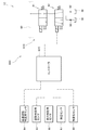
- the hydraulic drive system 1 includes a hydraulic pump 30, a steering drive circuit 31, and a work implement drive circuit 32.
- the hydraulic pump 30 is a so-called variable displacement hydraulic pump and is connected to the engine E.
- the hydraulic pump 30 is driven to rotate by the engine E, and discharges high-pressure hydraulic oil by rotating.
- a steering drive circuit 31 and a work machine drive circuit 32 are connected in parallel to the hydraulic pump 30, and hydraulic oil from the hydraulic pump 30 flows in parallel to the steering drive circuit 31 and the work machine drive circuit 32. ing.
- the steering drive circuit 31 has a meter-in passage 33 connected to the hydraulic pump 30, and hydraulic oil discharged from the hydraulic pump 30 flows through the meter-in passage 33.
- a steering control valve 34 is provided in the meter-in passage 33, and hydraulic oil discharged from the hydraulic pump 30 is guided to the steering control valve 34.
- the steering control valve 34 is connected to the steering cylinders 18L and 18R, and the hydraulic oil guided to the meter-in passage 33 flows to the steering cylinders 18L and 18R via the steering control valve 34.
- the steering control valve 34 has a main spool 34a, and the main spool 34a moves and changes its position so as to switch the direction of hydraulic oil flowing through the steering cylinders 18L and 18R. Further, in the steering control valve 34, the opening degree of the main spool 34a is adjusted in accordance with the position of the main spool 34a, and hydraulic oil having a flow rate corresponding to the opening degree is supplied to the steering cylinders 18L and 18R. It is about to flow.
- the main spool 34 a is connected to the steering device 35.
- the steering device 35 has a steering handle (not shown, hereinafter referred to as “handle”) that can be rotated, and outputs the first pilot oil and the second pilot oil according to the rotation direction of the handle. It is like that.
- the main spool 34a receives the pilot pressures p 1 and p 2 of the output first pilot oil and second pilot oil in a direction to oppose each other, and receives the first pilot pressure p 1 . It moved from the neutral position M1 in the first offset position in S11 that consists of a second neutral position M1 to receiving the pilot pressure p 2 to move to the second offset position S12.
- the meter-in passage 33 is connected to the proximal end chamber 18a of the right steering cylinder 18R and the distal end chamber 18b of the left steering cylinder 18L, and the tank 36 is connected to the right steering cylinder 18R. It connects to the distal end side chamber 18c and the proximal end side chamber 18d of the left steering cylinder 18L.
- the right steering cylinder 18R extends and the left steering cylinder 18L contracts, so that the front chassis 15 faces the left side relative to the rear chassis 14 and the traveling direction is switched.
- the meter-in passage 33 is connected to the front end side chamber 18c of the right steering cylinder 18R and the base end side chamber 18d of the left steering cylinder 18L, and the tank 36 is connected to the right steering cylinder.
- the base end side chamber 18a of 18R and the front end side chamber 18b of the left steering cylinder 18L are connected.
- the left steering cylinder 18L extends and the right steering cylinder 18R contracts, and the traveling direction is switched with respect to the rear chassis 14 with the front chassis 15 facing to the right.
- the steering device 35 outputs the first pilot oil and the second pilot oil at a flow rate corresponding to the turning speed of the handle, and the flow rates of the first pilot oil and the second pilot oil. Accordingly, the first pilot pressure p 1 and the second pilot pressure p 2 are increased.
- first pilot pressure p 1 and the second pilot pressure p 2 increases, the opening degree of the main spool 34a increases, steering cylinder 18L through the steering control valve 34, the hydraulic oil flowing respectively to 18R The flow rate increases.
- the steering cylinders 18L and 18R expand and contract at a speed corresponding to the turning speed of the handle, and the traveling direction is switched.
- the steering drive circuit 31 has a meter-in compensator (hereinafter, also simply referred to as “meter-in compensator”) 37 in order to adjust the flow rate of the hydraulic oil flowing through the steering cylinders 18L, 18R.
- meter-in compensator hereinafter, also simply referred to as “meter-in compensator”
- the meter-in compensator 37 is interposed upstream of the steering control valve 34 in the meter-in passage 33, and the inlet pressure p 3 of the steering control valve 34 and the outlet pressure p 4 of the steering control valve 34 are input. It is like that.
- Outlet pressure p 4 of the steering control valve 34 is a hydraulic pressure that is output in accordance with the opening degree of the main spool 34a, becomes larger as the opening degree of the main spool 34a is increased. In other words, the outlet pressure p 4 of the steering control valve 34 is adapted to be higher in response to the pressure rise in the hydraulic oil flowing to the steering actuator.
- the meter-in compensator 37 receives such two pressures p 3 and p 4 so as to oppose each other.
- the meter-in compensator 37 is a flow rate control valve, and controls the flow rate of hydraulic fluid flowing from the hydraulic pump 30 to the steering control valve 34 by an opening degree corresponding to the differential pressure between the two pressures p 3 and p 4. It has become.
- the steering drive circuit 31 is further provided with three relief valves 38-40.
- the first and second relief valves 38 and 39 allow the hydraulic oil flowing through the passage to flow when the hydraulic pressure in the passage connecting the steering control valve 34 and the chambers 18a to 18d of the steering cylinders 18L and 18R exceeds a predetermined pressure. It is discharged to the tank 36.
- the third main relief valve 40 is a relief valve, at the set pressure to the outlet pressure p 4 of the steering control valve 34 is predetermined, tank pilot oil flowing from the steering control valve 34 to meter-in compensator 37 36 is discharged.
- These three relief valves 38 to 40 restrict the flow rate of the hydraulic oil flowing through the steering cylinders 18L and 18R to keep the hydraulic oil pressure at a set pressure, and the hydraulic oil pressure guided to the steering cylinders 18L and 18R is a predetermined pressure. I try not to be more than that.
- the work machine drive circuit 32 has a bleed-off passage 41, and the upstream side of the bleed-off passage 41 is connected to the upstream side of the meter-in compensator 37 in the meter-in passage 33.
- the hydraulic oil discharged from the hydraulic pump 30 is guided to the bleed-off passage 41 together with the meter-in passage 33.
- a tilt control valve 43, a boom control valve 44, and a throttle 45 are interposed in that order from the upstream side, and the downstream side of the throttle 45 is connected to the tank 36.
- the tilt control valve 43 which is an actuator control valve, is connected to the tilt cylinder 23 and switches the flow of hydraulic oil in the bleed-off passage 41 toward the tilt cylinder 23 to drive the tilt cylinder 23. ing. More specifically, the tilt control valve 43 has a tilt spool 43a, and the tilt spool 43a moves from the neutral position M2 by operating the tilt lever 24 provided in the driver's seat 20. The position is changed. Then, by changing the position of the tilt spool 43a, the tilt control valve 43 switches the direction in which the hydraulic oil flows.
- the tilt control valve 43 configured as described above is a center open type directional switching valve, and when the tilt spool 43a is positioned at the neutral position M2, the tilt control valve 43 is opened (that is, a bleed-off passage). 41 is open), the opening degree is the largest. Then, the tilt spool 43a moves from the neutral position M2 toward the first and second offset positions S21 and S22, so that the opening degree of the tilt control valve 43 (that is, the tilt spool 43a according to the amount of movement of the tilt spool 43a) The opening degree of the bleed-off passage 41 becomes smaller.
- the amount of hydraulic oil flowing downstream from the tilt control valve 43 in the bleed-off passage 41 decreases as the operation amount of the tilt lever 24 increases, and by returning the tilt lever 24 to the original position. It has come to increase.
- a boom control valve 44 is interposed downstream from the tilt control valve 43.
- the boom control valve 44 which is an actuator control valve, is connected to the boom cylinder 22 and drives the boom cylinder 22 by switching the flow of hydraulic oil in the bleed-off passage 41 toward the boom cylinder 22. It is like that. More specifically, the boom control valve 44 has a boom spool 44a, and the boom spool 44a is moved from the neutral position M3 by operating the elevating lever 25 provided in the driver's seat 20. The position is changed. Then, by changing the position of the boom spool 44a, the boom spool 44a switches the direction in which the hydraulic oil flows.
- the boom spool 44a can be moved from the first offset position S31 to the third offset position S33 by further operating the elevating lever 25.
- the third offset position S33 the distal end side chamber 22a and the proximal end side chamber 22b of the boom cylinder 22 are connected to the tank 36, the holding force of the boom cylinder 22 is lost, and the bucket 11 is lowered by its own weight.
- the boom control valve 44 configured in this way is a center open type directional control valve, and the bleed-off passage 41 is opened when the boom spool 44a is located at the neutral position M3, and the opening degree is the largest. It has become.
- the opening degree of the bleed-off passage 41 decreases according to the amount of movement of the boom spool 44a. Therefore, the amount of hydraulic oil flowing downstream from the boom control valve 44 in the bleed-off passage 41 decreases as the operation amount of the elevating lever 25 increases, and by returning the elevating lever 25 to the original position. It has come to increase.
- a throttle 45 is interposed downstream of the boom control valve 44.
- the throttle 45 is positioned between the boom control valve 44 and the tank 36 in the bleed-off passage 41, and the hydraulic oil that has passed through the tilt control valve 43 and the boom control valve 44 passes through the throttle 45. 36 is discharged. Therefore, on the upstream side of the throttle 45, a pressure corresponding to the flow rate of the hydraulic oil that passes through the tilt control valve 43 and the boom control valve 44 and is guided to the throttle 45 is generated.
- a negative control passage 46 is connected between the throttle 45 and the boom control valve 44, and the pressure generated on the upstream side of the throttle 45 is tilted to the servo mechanism 47 of the hydraulic pump 30 via the negative control passage 46. Guided as a command signal.
- the hydraulic pump 30 is a variable displacement hydraulic pump as described above, and has a swash plate 30a.
- the capacity of the hydraulic pump 30 is changed by inclining the swash plate 30a, and the servo mechanism 47 controls the tilt angle of the swash plate 30a of the hydraulic pump 30 in accordance with the tilt command signal. ing. More specifically, the servo mechanism 47 decreases the displacement of the hydraulic pump 30 by decreasing the tilt angle of the swash plate 30a when the pressure of the tilt command signal increases. Thereby, the discharge amount of the hydraulic pump 30 decreases. On the other hand, when the pressure of the tilt command signal decreases, the servo mechanism 47 increases the tilt angle of the swash plate 30a to increase the capacity of the hydraulic pump 30. Thereby, the discharge amount of the hydraulic pump 30 increases.
- the discharge amount of the hydraulic pump 30 is controlled according to the flow rate flowing through the throttle 45, that is, the discharge amount of the hydraulic pump 30 is controlled by negative control. Further, in the work machine drive circuit 32, the flow rate of the hydraulic oil discharged from the hydraulic pump 30 and flowing into the steering drive circuit 31 is adjusted, that is, the flow rate of the hydraulic oil bleed off from the hydraulic pump 30 to the bleed-off passage 41 is adjusted.
- a bleed-off compensator (hereinafter simply referred to as “bleed-off compensator”) 42 is provided for control.
- the bleed-off compensator 42 is provided upstream of the tilt control valve 43 in the bleed-off passage 41. Bleed-off pressure compensator 42, and an outlet pressure p 4 of the inlet pressure of the bleed-off pressure compensator 42 p 5 and the steering control valve 34 is input as a pilot pressure, to anti the input pressure p 5 and outlet pressure p 4 together It is receiving pressure in the direction. Bleed-off pressure compensator 42 is a flow control valve having a spool 42a, the spool 42a is moved in the position corresponding to the pressure difference between the input pressure p 5 and outlet pressure p 4. In addition, the flow rate of the hydraulic oil that is bleed off downstream of the bleed-off compensator 42 is controlled by the opening degree corresponding to the position of the spool 42a.
- a first bypass passage 48 is formed between the steering drive circuit 31 and the work implement drive circuit 32, and the outlet pressure p 4 of the steering control valve 34 is guided to the bleed-off compensator 42 by this bypass passage 48. ing.
- An electromagnetic switching valve 49 is interposed in the first bypass passage 48, and the electromagnetic switching valve 49 is connected to the second bypass passage 50.
- the electromagnetic switching valve 49 is connected to the upstream side of the bleed-off compensator 42 in the bleed-off passage 41 through the second bypass passage 50.
- the electromagnetic switching valve 49, operation buttons 51 are electrically connected to the bleed pilot pressure to be input when the operation button 51 is operated to bleed-off pressure compensator 42 from the outlet pressure p 4 of the steering control valve 34 office computer so that the switch to the inlet pressure p 5 of the pen 42.
- the differential pressure between the two pilot pressures input to the bleed-off compensator 42 becomes zero, and the spool 42a of the bleed-off compensator 42 closes the bleed-off passage 41 by the spring 42b.
- the bleed-off passage 41 is forcibly closed by being energized.
- the work machine drive circuit 32 configured as described above includes a plurality of relief valves 52 to 55.
- the first relief valve 52 is provided in parallel to the throttle 45 in the bleed-off passage 41, and when the upstream side of the throttle 45 reaches a predetermined pressure or higher, the hydraulic oil flowing therethrough is supplied to the tank 36 via the relief valve 52. To be discharged.
- the relief valves 53 to 55 are provided between the tilt control valve 43 and the front end side chamber 23a of the tilt cylinder 23, between the tilt control valve 43 and the base end side chamber 23b of the tilt cylinder 23, and the boom control valve 44.
- the three relief valves 53 to 55 are also connected to the passages between the front end side chamber 22a of the boom cylinder 22 and each of the three relief valves 53 to 55 is hydraulic oil when the hydraulic pressure in each of the passages exceeds a predetermined pressure. Is discharged into the tank 36.
- the work machine drive circuit 32 is provided with a main relief valve 56.
- the main relief valve 56 is provided in parallel with the bleed-off compensator 42, and discharges hydraulic oil from the hydraulic pump 30 to the tank 36 when the discharge pressure of the hydraulic pump 30 exceeds a predetermined pressure. .
- the main relief valve 56 can keep the pressure of the hydraulic oil flowing from the hydraulic pump 30 to the work machine drive circuit 32 below a specified pressure.
- the working machine driving circuit 32 when the operation button 51 is not operated, in the direction in which the spool 42a of the bleed-off pressure compensator 42 by the outlet pressure p 4 of the steering control valve 34 is reduced to open the bleed-off passage 41
- the hydraulic oil flows to the downstream side of the spool 42a of the bleed-off passage 41.
- the tilt lever 24 or the lift lever 25 when the tilt lever 24 or the lift lever 25 is operated, the spools 43a and 44a of the control valves 43 and 44 corresponding to the operated lever move from the neutral positions M2 and M3, and the hydraulic oil responds.
- the cylinders 23 and 22 to be operated. Thereby, the bucket 11 moves up and down or tilts according to the operated lever.
- the spools 43a and 44a are moved from the neutral positions M2 and M3, the opening degree of the bleed-off passage 41 is reduced and the flow rate flowing through the throttle 45 is reduced. Then, the pressure of the tilt command signal decreases, and the servo mechanism 47 increases the tilt angle of the swash plate 30a of the hydraulic pump 30 based on the tilt command signal to increase the discharge amount of the hydraulic pump 30. Conversely, when the tilt lever 24 or the lift lever 25 is not operated and the spools 43a and 44a are returned to the neutral positions M2 and M3, the flow rate flowing through the throttle 45 increases. Then, the pressure of the tilt command signal is increased, and the servo mechanism 47 reduces the tilt angle of the swash plate 30a of the hydraulic pump 30 based on the tilt command signal and decreases the discharge amount of the hydraulic pump 30.
- the main spool 34a of the steering control valve 34 moves from the neutral position M1 in accordance with the operation amount of the handle.
- the outlet pressure p 4 of the steering control valve 34 increases, and the meter-in compensator 37 moves in a direction to open the meter-in passage 33.
- the hydraulic oil from the hydraulic pump 30 is guided to the steering cylinders 18L and 18R via the steering control valve 34, and the hydraulic oil expands and contracts in the steering cylinders 18L and 18R.
- the traveling direction of the wheel loader 2 is switched to the corresponding direction.
- the working machine driving circuit 32 when the operation button 51 is not operated, the spool 42a of the bleed-off pressure compensator 42 by the outlet pressure p 4 of the steering control valve 34 becomes large in the direction of closing the bleed-off passage 41
- the flow rate of the hydraulic oil that moves and flows downstream of the bleed-off compensator 42 in the bleed-off passage 41 is limited.
- the flow rate of the hydraulic oil that is bleed-off from the meter-in passage 33 to the bleed-off passage 41 can be suppressed, that is, the hydraulic oil can be preferentially flowed to the steering drive circuit 31. Accordingly, the steering cylinders 18L and 18R can be moved with priority with respect to the bucket 11.
- the outlet pressure p 3 of the meter-in pressure compensator 37 continues to rise with increasing degree of opening of the meter-in compensator 37, the outlet pressure p 4 of the steering control valve 34, when it comes to the set pressure main being adapted to the relief valve 40 is opened, it is maintained as the outlet pressure p 4 is under the set pressure. Therefore, when the outlet pressure p 3 of the meter-in pressure compensator 37 increases, eventually meter-in compensator 37 is moved in the direction to close the meter passages 33, the steering cylinders 18L, the flow rate flowing through the 18R limit. Therefore, the maximum pressure of the hydraulic oil flowing through the steering cylinders 18L and 18R is limited to a predetermined pressure corresponding to the set pressure.
- the electromagnetic switching valve 49 is operated and the pilot pressure acting on the bleed-off compensator 42 is changed from the outlet pressure p 4 of the steering control valve 34 to the bleed-off compensator 42. It is switched to the inlet pressure p 5.
- the bleed-off compensator 42 is forcibly closed in the bleed-off passage 41. By being closed, the discharge amount of the hydraulic pump 30 is increased by the servo mechanism 47, and the oil pressure in the meter-in passage 33 and the bleed-off passage 41 is increased.
- the main relief valve 56 When the hydraulic pressure in the bleed-off passage 41 becomes equal to or higher than the specified pressure, the main relief valve 56 is opened and the hydraulic oil in the bleed-off passage 41 is discharged to the tank 36.
- the engine E can be loaded by forcibly closing the bleed-off passage 41 and discharging the hydraulic oil from the main relief valve 56. If the handle of the steering device 35 is operated while the operation button 51 is being operated, the meter-in compensator 37 moves to open the meter-in passage 33 as in the case where the operation button 51 is not operated, and the steering drive circuit 31 The hydraulic oil flows preferentially.
- the hydraulic drive system 1 when the steering wheel of the steering device 35 is operated, the hydraulic oil flows preferentially to the steering drive circuit 31 and is related to whether or not the bucket 11 is operating.
- the steering cylinders 18L and 18R move according to the operation of the steering wheel. That is, the steering cylinders 18L and 18R have high responsiveness to steering wheel operations. This high responsiveness may reduce the straightness during high speed running. Therefore, the hydraulic drive system 1 includes the flow rate adjusting means 60 in order to improve the straight traveling performance during high speed traveling.
- the flow rate adjusting means 60 is configured to determine whether or not the state of the wheel loader 2 satisfies the steering restriction condition. When it is further determined that the steering restriction condition is satisfied, the operation that flows to the steering cylinders 18L and 18R is performed. The flow rate of the oil is decreased from the flow rate corresponding to the handle operation amount of the steering device 35. As a result, the steering cylinders 18L and 18R reduce the responsiveness to the operation of the steering wheel, and improve the straight traveling performance during high speed traveling.
- the flow rate adjusting means 60 has an outlet pressure switching valve 61 and a controller 62.
- the outlet pressure switching valve 61 that is a flow rate adjusting mechanism is connected to a pilot passage 63 that connects the bypass passage 48 and the meter-in compensator 37.
- the pilot passage 63 is the outlet pressure p 4 of the steering control valve 34 through the bypass passage 48 is guided, in the meter-in compensator 37, the outlet pressure p 4 led to the pilot passage 63 as a pilot pressure It is designed to be entered.
- the pilot passage 63 is connected to the tank 36 via the outlet pressure switching valve 61.
- the outlet pressure switching valve 61 is a so-called electromagnetic switching valve, and connects or shuts off the pilot passage 63 and the tank 36 according to a command signal (flow rate regulation command) input thereto. Yes.
- a throttle 69 is interposed between the outlet pressure switching valve 61 and the tank 36, and the flow rate of pilot oil flowing from the pilot passage 63 to the tank 36 via the outlet pressure switching valve 61 is limited by the throttle 69. It has become so.
- the outlet pressure switching valve 61 is electrically connected to the controller 62, and a command signal is input from the controller 62.
- the controller 62 determines whether or not the state of the wheel loader 2 satisfies the steering regulation condition.
- Steering regulation conditions include that the wheel loader 2 is in a traveling posture, that the wheel loader 2 is in a traveling state, and that the wheel loader 2 is in a high speed state.
- the steering regulation condition need not include all the three conditions described above, and it is sufficient that at least the wheel loader 2 is in a high speed state.
- the controller 62 has three sensors 64, 64, 66, which are vehicle state detection devices, specifically a high-speed state, in order to determine whether or not the steering restriction condition is satisfied.
- the determination sensor 64, the posture determination sensor 65, and the travel determination sensor 66 are electrically connected.
- the high speed state determination sensor 64 is a sensor for determining whether or not the wheel loader 2 is traveling at high speed.
- the high speed state determination sensor 64 is a vehicle speed sensor, for example, and outputs a signal for detecting the vehicle speed of the wheel loader 2 to the controller 62.
- the controller 62 detects the speed of the wheel loader 2 based on the output from the vehicle speed sensor, that is, the vehicle speed, and determines whether or not the wheel loader 2 is in a high speed state according to the detected vehicle speed.
- the high speed state determination sensor 64 may be a gear position detection sensor or an accelerator pedal operation amount sensor.
- the controller 62 detects the gear position or the accelerator pedal operation amount based on the output from these sensors, and detects them. It may be determined whether or not the vehicle is in a high speed state based on the detection result.
- the posture determination sensor 65 is a sensor for determining whether or not the wheel loader 2 is in the driving posture.
- the posture determination sensor 65 is, for example, an angle sensor for the boom 21, and outputs a signal for detecting the rotation angle of the boom 21 to the controller 62.
- the controller 62 detects the rotation of the boom 21 based on the output signal from the angle sensor, and determines whether or not the wheel loader 2 is in the operating posture based on the detected rotation angle.
- the attitude determination sensor 65 may be an angle sensor that detects the position of the bucket 11 or a pressure sensor that detects the holding pressure of the boom cylinder 22 or the tilt cylinder 23, and the controller 62 outputs from these sensors.
- the rotation angle or holding pressure of the boom 21 may be detected based on the above, and it may be determined whether or not the wheel loader 2 is in the operating posture based on the detection results.
- the traveling determination sensor 66 is a sensor for determining whether or not the wheel loader 2 is in a traveling state.
- the traveling determination sensor 66 includes, for example, a rotational speed sensor for detecting the rotational speed of the engine E and the output rotational speed of the torque converter, respectively.
- the torque converter is a power transmission mechanism for transmitting the output torque of the engine E to the wheels 13.
- the two sensors are configured to output to the controller 62 signals for detecting the rotational speed of the engine E and the output rotational speed of the torque converter, that is, the rotational speeds on the input side and output side of the torque converter.
- the controller 62 calculates a speed ratio between the rotational speeds of the input side and the output side of the torque converter based on the output signal from the sensor, and determines whether or not the wheel loader 2 is in a traveling state based on the speed ratio.
- the travel determination sensor 66 may include, in place of the two rotation speed sensors, a pressure sensor that detects a release pressure or a brake pressure of the parking brake provided in the wheel loader 2, and a forward / reverse detection sensor.
- the controller 62 may determine whether or not the wheel loader 2 is in a traveling state based on detection results from these sensors.
- the traveling determination sensor 66 may be a vehicle speed sensor, and the controller 62 may determine whether or not the wheel loader 2 is traveling based on an output signal from the sensor.
- an oil temperature sensor 67 and a steering wheel angular displacement sensor 68 are electrically connected to the controller 62.
- the oil temperature sensor 67 which is a vehicle state detection device is a sensor for detecting the oil temperature of the hydraulic oil discharged from the hydraulic pump 30.
- the oil temperature sensor 67 is connected to the tank 36, for example, and outputs a signal for detecting the oil temperature of the hydraulic oil to the controller 62.
- the controller 62 detects the oil temperature of the hydraulic oil based on the output signal from the oil temperature sensor 67.
- An angular displacement sensor 68 for a steering wheel which is a vehicle state detection device, is provided on the steering wheel of the steering device 35, and is a sensor for detecting the angular displacement amount of the steering wheel.
- the angular displacement sensor 68 outputs a signal for detecting the amount of angular displacement of the handle to the controller 62.
- the controller 62 detects the rotational speed of the handle based on the output signal from the angular displacement sensor 68.
- the controller 62 configured in this manner determines whether or not the state of the wheel loader 2 satisfies the steering restriction condition based on the signals from the sensors 64 to 66. Further, the controller 62 satisfies a steering restriction prohibition condition to be described later based on the detected oil temperature and steering wheel rotation speed and the vehicle speed of the wheel loader 2 detected based on the output signal of the high speed state determination sensor 64. It is determined whether or not. The controller 62 outputs a command signal to the outlet pressure switching valve 61 in accordance with whether or not the steering restriction condition and the steering restriction prohibition condition are satisfied.
- Step S101 to S103 are determination processing for determining whether or not the state of the wheel loader 2 satisfies the steering restriction condition.
- the order which determines whether the satisfaction of a condition is sufficient it is not limited to the order demonstrated below, What kind of order may be sufficient.
- step S101 which is an operation posture determination step
- the controller 62 determines whether or not the wheel loader 2 is in the operation posture. More specifically, the controller 62 detects the rotation angle of the boom 21 based on the output signal from the posture determination sensor 65, and determines whether or not the rotation angle is within a predetermined threshold range. Determine. When the rotation angle is outside the threshold range, the controller 62 determines that the wheel loader 2 is in the working posture in which excavation or loading is performed, and determines again whether or not the wheel loader 2 is in the operation posture. When the rotation angle is within the threshold value range, the controller 62 determines that the wheel loader 2 is in an operation posture capable of high speed operation, and the process proceeds to step S102.
- Step S102 which is a traveling state determination step, is a step of determining whether or not the wheel loader 2 is in a traveling state, that is, whether or not the controller 62 wheel loader 2 is traveling. More specifically, the controller 62 calculates the speed ratio between the rotational speeds of the input side and the output side of the torque converter based on the output signal from the travel determination sensor 66, and this speed ratio is equal to or greater than a predetermined threshold value. It is determined whether it is (for example, 0.4 or more). When the speed ratio is equal to or less than the threshold value, the controller 62 determines that the wheel loader 2 is working or the wheel loader 2 is not traveling, and the process returns to step S101. When the speed ratio is equal to or greater than the threshold, the controller 62 determines that the wheel loader 2 is traveling, and the process proceeds to step S103.
- the high speed state determination step S103 is a step of determining whether or not the wheel loader 2 is traveling at high speed. More specifically, the controller 62 detects the vehicle speed of the wheel loader 2 based on an output signal from the high speed state determination sensor 64, and the vehicle speed is equal to or higher than a predetermined threshold (for example, 20 km / h or higher). It is determined whether or not. When the vehicle speed is less than or equal to the threshold, the controller 62 determines that the wheel loader 2 is not traveling at high speed, and the process returns to step S101. When the vehicle speed is equal to or higher than the threshold, it is determined that the wheel loader 2 is traveling at a high speed. As described above, in Steps S101 to S103, if all the conditions included in the steering restriction condition (that is, the driving posture, the running state, and the high speed state) are satisfied, The process is started and the process proceeds to step S104.
- a predetermined threshold for example, 20 km / h or higher.
- step S104 which is a steering restriction prohibition condition determination step, the controller 62 determines whether or not the wheel loader 2 satisfies the steering restriction prohibition condition.
- the steering restriction prohibition condition includes that the oil temperature T of the hydraulic oil is T1 (for example, 20 ° C.) or less and that the steering wheel rotation speed N is N1 (for example, 60 rpm) or more. Note that the steering restriction prohibition condition does not necessarily include two, and it is sufficient that at least one is included. The determination procedure will be described in detail.
- the controller 62 detects the oil temperature T and the steering wheel rotation speed N based on the output signals from the oil temperature sensor 67 and the angular displacement sensor 68, and based on these, the steering regulation is performed.
- step S105 It is determined whether or not at least one of the conditions included in the prohibition condition is satisfied. If it determines with the controller 62 being satisfied, it will return to step S101, without performing steering control. On the other hand, if it determines with the controller 62 not being satisfied, it will transfer to step S105.
- step S ⁇ b> 105 which is an outlet pressure switching process
- the controller 62 outputs a command signal to the outlet pressure switching valve 61.
- the pilot passage 63 is connected to the tank 36 via the outlet pressure switching valve 61, and part of the pilot oil flowing through the pilot passage 63 is released to the tank 36 via the throttle 69.
- reduced outlet pressure p 4 of the steering control valve 34 because the differential pressure between the inlet pressure p 3 of the steering control valve 34 is increased, the hydraulic oil meter-in compensator 37 to the steering control valve 34 Reduce the supply flow rate.
- the flow rate flowing through the main spool 34a decreases, and the flow rate of the hydraulic oil flowing through the steering cylinders 18L and 18R can be reduced from the flow rate corresponding to the handle operation amount of the steering device 35.
- the steering cylinders 18L and 18R can reduce the responsiveness to the operation of the steering wheel, and can improve the straight traveling performance during high-speed traveling.
- step S106 which is a regulation release determination process
- the controller 62 determines again whether or not the state of the wheel loader 2 satisfies the steering regulation condition.
- the process returns to step S104, and when it is determined that the steering restriction condition is not satisfied, the process proceeds to step S107.
- step S ⁇ b> 107 which is a regulation release step
- the controller 62 stops the command signal to the outlet pressure switching valve 61 and shuts off the pilot passage 63 and the tank 36.
- a flow rate corresponding to the steering operation amount of the steering device 35 flows to the steering cylinders 18L and 18R.
- the process returns to step S101.
- the response of the steering cylinders 18L and 18R to the steering operation of the steering device 35 may be reduced. it can. Thereby, the straight traveling property of the wheel loader 2 during high-speed traveling can be improved.
- the hydraulic drive system 1A of the second embodiment is similar in configuration to the hydraulic drive system 1 of the first embodiment.
- the configuration of the hydraulic drive system 1A of the second embodiment will be described mainly with respect to differences from the hydraulic drive system 1 of the first embodiment, and the same components will be denoted by the same reference numerals and the description thereof will be given. May be omitted.
- the hydraulic drive system 1A of the second embodiment includes a flow rate adjusting means 60A, and the flow rate adjusting means 60A includes an outlet pressure switching valve 61A and a controller 62.
- the outlet pressure switching valve 61 ⁇ / b> A is a so-called electromagnetic switching valve and is connected to the bypass passage 48 and the tank 36.
- the outlet pressure switching valve 61 ⁇ / b> A connects or blocks between the pilot passage 63 and the tank 36 in accordance with a command signal (flow rate regulation command) from the controller 62.
- the outlet pressure switching valve 61A configured in this way is connected to the pilot passage 63 via the bypass passage 48 in a state where the operation button 51 is not operated.
- the outlet pressure switching valve 61A connects between the pilot passage 63 and the tank 36 in accordance with a command signal.
- the pilot oil flowing through the bypass passage 48 is discharged to the tank 36 via the outlet pressure switching valve 61A.
- pilot pressure p 4 is input to the bleed-off pressure compensator 42 reduces, it is possible to make it difficult to close the bleed-off pressure compensator 42. Further, it is possible to make it difficult to open the meter-in compensator 37 by p 4 is reduced.
- the flow rate flowing to the steering control valve 34 is reduced, and the flow rate of the hydraulic oil flowing to the steering cylinders 18L and 18R is reduced. ing. As a result, the flow rate of the hydraulic oil flowing through the steering cylinders 18L and 18R can be reduced without substantially affecting the sense of steering operation of the steering device 35.
- hydraulic drive system 1A operates in the same manner as the hydraulic drive system 1 of the first embodiment and has the same effects.
- the steering device 35 of the hydraulic drive system 1B of the third embodiment is configured in the same manner as the hydraulic drive systems of the first and second embodiments, and includes a power steering unit 70.
- the power steering unit 70 includes a direction switching valve 71 and a metering mechanism 72.
- the direction control valve 71 has a spool 71a, and a handle 74 is connected to the spool 71a.
- the handle 74 is configured to be able to rotate, and the spool 71a moves when the handle 74 is rotated.
- the direction control valve 71 is connected to the upstream side of the meter-in compensator 37 in the meter-in passage 33 through the supply passage 75, and is connected to the tank 36 through the tank passage 76. Further, the direction control valve 71 is connected to the main spool 34 a of the steering control valve 34 via the first pilot passage 77 and the second pilot passage 78, and is also connected to the metering mechanism 72.
- the metering mechanism 72 is a so-called pump, and has two supply / discharge ports 72a and 72b.
- the metering mechanism 72 is connected to a handle 74 via a shaft 79, and sucks the pressure oil from one intake / exhaust port 72a (or the other intake / exhaust port 72b) in accordance with the turning operation of the handle 74, and Pilot oil is discharged from the intake / exhaust port 72b (or one intake / exhaust port 72a).
- the two intake / exhaust ports 72a and 72b are connected to the direction control valve 71 via intake / exhaust passages 72c and 72d, respectively.
- the direction control valve 71 connected with a plurality of passages moves the spool 71a in accordance with the turning operation of the handle, and switches the flow of pilot oil in accordance with the position of the spool 71a. More specifically, when the handle 74 is turned, the spool 71a moves from the neutral position M4 to the first offset position S41 and the second offset position S42 according to the rotation direction of the handle 74, respectively. When the spool 71a moves to the first offset position S41, the supply passage 75 is connected to one intake / exhaust passage 72c, and the other intake / exhaust passage 72d is connected to the first pilot passage 77.
- the first pilot oil having a flow rate corresponding to the operation amount of the handle 74 is guided to the first pilot passage 77.
- the second pilot passage 78 is connected to the tank passage 76 when the spool 71a moves to the first offset position S41.
- the first pilot passage 77 and the second pilot passage 78 are connected to each other by a communication passage 81, and the first pilot oil flowing through the first pilot passage 77 is connected to the tank by the second pilot passage 78 being connected to the tank. Flow through 81 to the second pilot passage 78.
- a throttle 82 is interposed in the communication passage 81, and the first pilot pressure p 1 corresponding to the flow rate flowing through the first pilot passage 77 when the first pilot oil passes through the throttle 82 is the first pilot passage 77. Occurs.
- the first pilot pressure p 1 acts on the main spool 34a, the position corresponding to the operation amount of the steering wheel 74, that is, to move the main spool 34a toward the first offset position S11.
- the supply passage 75 is connected to the other intake / exhaust passage 72d, and the one intake / exhaust passage 72c is connected to the second pilot passage 78. Accordingly, the second pilot oil having a flow rate corresponding to the operation amount of the handle 74 is guided to the second pilot passage 78. Further, when the spool 71a moves to the second offset position S42, the first pilot passage 77 is connected to the tank passage 76, and the second pilot oil passes from the second pilot passage 78 through the communication passage 81 to the first pilot passage. It flows to 77.
- a second pilot pressure p 2 corresponding to the flow rate flowing through the second pilot passage 78 is generated in the second pilot passage 78.
- the steering device 35 thus configured is provided with a flow rate adjusting means 60B.
- the flow rate adjusting means 60B controls the position of the main spool 34a by adjusting the flow rates of the first and second pilot oils flowing in the first and second pilot passages 77 and 78, respectively, to the steering cylinders 18L and 18R.
- the flow rate of the flowing hydraulic oil is reduced from the flow rate corresponding to the handle operation amount of the steering device 35.
- the configuration of the flow rate adjusting means 60B will be specifically described.
- the flow rate adjusting means 60B has two open / close switching valves 61L and 61R and a controller 62B. One open / close switching valve 61L is connected to the first pilot passage 77, and the other open / close switching valve 61R is connected to the second pilot passage 78.
- the two on-off switching valves 61L and 61R are so-called electromagnetic switching valves, and connect or shut off the pilot passages 77 and 78 and the tank 36 in accordance with a command signal (flow rate regulation command) input thereto. It has become. Further, throttles 83 and 84 are interposed between the two on-off switching valves 61L and 61R and the tank 36, respectively, and a part of the flow rate of the pilot oil flowing through the pilot passages 77 and 78 is throttled 83 and 84. It is discharged to the tank 36 via The two open / close switching valves 61L and 61R configured as described above are electrically connected to the controller 62B, and a command signal is input from the controller 62B.
- the controller 62B is electrically connected to the sensors 64 to 68 in the same manner as the controller 62 of the first embodiment, and the wheel loader 2 is controlled by the steering restriction condition based on the output signals from these sensors. In addition, it is determined whether or not the steering restriction prohibition condition is satisfied. Thus, the controller 62B outputs a command signal to the open / close switching valves 61L and 61R.
- the controller 62B outputs a command signal to the open / close switching valves 61L and 61R.
- hydraulic drive system 1B of the third embodiment has the same effects as the hydraulic drive system 1 of the first embodiment.
- the hydraulic drive system 1C of the fourth embodiment includes a flow rate adjusting device 60C, and the flow rate adjusting device 60C includes a flow rate control mechanism 61C and a controller 62C.
- the flow rate control mechanism 61 ⁇ / b> C is connected to the pilot passage 63 and the tank 36.
- the flow rate control mechanism 61C connects the pilot passage 63 and the tank 36 in response to a command signal input thereto, and is discharged from the pilot passage 63 to the tank 36 in response to a flow rate switching signal input thereto.
- the pilot oil flow is switched.
- the flow control mechanism 61C includes an electromagnetic switching valve 91, a direction switching valve 92, a first throttle 93, and a second throttle 94.
- the electromagnetic switching valve 91 is connected to the pilot passage 63 and the direction switching valve 92, and connects or shuts off the pilot passage 63 and the direction switching valve 92 according to a command signal input thereto. It is like that.
- the direction switching valve 92 is connected to the electromagnetic switching valve 91, the first throttle 93, and the second throttle 94, and the connection destination of the electromagnetic switching valve 91 is set to the first according to the flow rate switching signal input thereto. It is connected to one of the diaphragm 93 and the second diaphragm 94.
- the first diaphragm 93 and the second diaphragm 94 are connected to the tank 36.
- the first throttle 93 and the second throttle 94 have different flow path cross sections, and the flow path cross section of the first throttle 93 is set to be smaller than the flow path cross section of the second throttle 94.
- the electromagnetic switching valve 91 and the direction switching valve 92 are electrically connected to the controller 62C.
- the controller 62C is electrically connected to the high-speed state determination sensor 64, the posture determination sensor 65, and the travel determination sensor 66, and is also electrically connected to the oil temperature sensor 67 and the angular displacement sensor 68. Yes.
- the controller 62C determines whether or not the steering restriction condition is satisfied based on the signals from the sensors 64 to 66, and whether or not the steering restriction prohibition condition is satisfied based on the signals from the sensors 67 and 68. Determine whether or not.
- the controller 62C outputs a command signal to the electromagnetic switching valve 91 in accordance with whether or not the steering restriction condition and the steering restriction prohibition condition are satisfied.
- the controller 62C determines whether or not the flow rate switching condition is satisfied based on the output signal from the high speed state determination sensor 64.
- the flow rate switching condition is that the vehicle speed V of the wheel loader 2 is V1 (for example, 30 km / h) or more.
- the flow rate switching condition is that the oil temperature T is T 2 (> T1) or more and the steering wheel rotation speed N1 may be N2 ( ⁇ N1) or less, and these three conditions (that is, conditions relating to vehicle speed, oil temperature, and steering wheel rotation speed). You may make it the conditions that at least 1 should be satisfied.
- the controller 62C determines that the flow rate switching condition is satisfied, the controller 62C outputs a flow rate switching signal to the direction switching valve 92.
- step S101 Similar to the hydraulic drive system 1 of the first embodiment, it is determined in steps S101 to S103 whether or not the steering restriction condition is satisfied. If it is determined that the steering restriction condition is satisfied, the process proceeds to step S104. In step S104, it is determined whether or not the steering restriction prohibition condition is satisfied. If it is satisfied, the process returns to step S101. On the other hand, if it is determined that it is not satisfied, the process proceeds to step S205.
- step S205 which is a flow rate switching condition determination step
- the controller 62C determines whether or not the flow rate switching condition is satisfied in order to switch the flow rate of the pilot oil flowing to the tank 36 depending on whether the flow rate switching condition is satisfied. If it is determined that the flow rate switching condition is not satisfied, the process proceeds to step S206. If it is determined that the flow rate switch condition is satisfied, the process proceeds to step S207.
- step S206 which is the first flow rate switching step
- the controller 62C outputs a command signal to the electromagnetic switching valve 91 to connect between the pilot passage 63 and the direction switching valve 92.
- part of the pilot oil flowing through the pilot passage 63 is released to the tank 36 via the direction switching valve 92 and the first throttle 93.
- the steering cylinders 18L and 18R can reduce the responsiveness to the operation of the steering wheel, and can improve the straight traveling performance during high-speed traveling.
- the process proceeds to step S106.
- Steps S106 and S107 are the same as steps S106 and S107 of the high-speed steering control executed by the hydraulic drive system 1 according to the first embodiment, and a description thereof will be omitted. The same applies to the following description.
- step S207 which is the second flow rate switching step
- the controller 62C outputs a command signal to the electromagnetic switching valve 91 to connect between the pilot passage 63 and the direction switching valve 92.
- the controller 62 ⁇ / b> C outputs a flow rate switching signal to the direction switching valve 92 and connects the electromagnetic switching valve 91 to the second throttle 94.
- part of the pilot oil flowing through the pilot passage 63 is released to the tank 36 via the direction switching valve 92 and the second throttle 94. Since the second throttle 94 has a larger flow path area than the first throttle 93, more pilot oil than the first throttle 93 is discharged from the pilot passage 63 to the tank 36 and is steered more than in the first flow rate switching step.
- outlet pressure p 4 of use control valve 34 is further reduced. Then, further increases the differential pressure p 3 of the inlet pressure and the outlet pressure p 4 of the steering control valve 34, from the flow rate corresponding steering cylinder 18L, the flow rate of the hydraulic oil flowing in the 18R to the steering wheel operation amount of the steering device 35 Further reduction can be achieved. Thereby, the steering cylinders 18L and 18R can further reduce the responsiveness to the operation of the steering wheel, and can further improve the straight traveling performance during high-speed traveling.
- the process proceeds to step S106.
- the hydraulic drive system 1C configured as described above adjusts the responsiveness to the handle operation according to whether or not the flow rate switching condition is satisfied, so that the response when the speed is relatively slow even at high speed. Therefore, it is possible to prevent the operability from being excessively decreased due to the excessive decrease in performance. Further, as the oil temperature T becomes lower, it is possible to prevent the responsiveness from being excessively lowered by suppressing the amount of decrease in the flow rate of the hydraulic oil guided to the steering cylinders 18L and 18R with respect to the operation amount of the steering device.
- the hydraulic drive system 1C has the same effects as the hydraulic drive system 1 of the first embodiment.
- the hydraulic drive system 1D of the fifth embodiment includes a flow rate adjusting device 60D, and the flow rate adjusting device 60D includes a flow rate control mechanism 61D and a controller 62D.
- the flow rate control mechanism 61 ⁇ / b> D is connected to the pilot passage 63 and the tank 36.
- the flow rate control mechanism 61D switches the flow rate of pilot oil discharged from the pilot passage 63 to the tank 36 in accordance with a flow rate switching signal input thereto.
- the flow control mechanism 61D has a pilot pump 95, an electromagnetic proportional valve 96, and a flow control valve 97.
- the pilot pump 95 discharges pressure oil, and the discharged pressure oil is guided to the electromagnetic proportional valve 96.
- the electromagnetic proportional valve 96 is connected to the pilot pump 95 and the flow control valve 97.
- the electromagnetic proportional valve 96 is supplied with a flow rate switching signal (flow rate regulation signal) and opens between the pilot pump 95 and the flow rate control valve 97 with an opening corresponding to the flow rate switching signal. ing.
- a flow rate switching pilot pressure corresponding to the flow rate switching signal is guided to the flow rate control valve 97.
- the flow rate control valve 97 is connected to the pilot passage 63 and the tank 36, and the spool 97 a moves according to the flow rate switching pilot pressure guided from the electromagnetic proportional valve 96.
- the flow rate control valve 97 opens between the pilot passage 63 and the tank 36 at an opening degree corresponding to the flow rate switching pilot pressure by the movement of the spool 97a. That is, the flow rate control valve 97 discharges pilot oil having a flow rate corresponding to the flow rate switching signal from the pilot passage 63 to the tank 36.
- the controller 62D is electrically connected to the electromagnetic proportional valve 96 of the flow rate control mechanism 61D configured as described above.
- the controller 62D is electrically connected to the high speed state determination sensor 64, the posture determination sensor 65, and the travel determination sensor 66, and is also electrically connected to the oil temperature sensor 67 and the angular displacement sensor 68. Yes.
- the controller 62D determines whether or not the steering restriction condition is satisfied based on the signals from the sensors 64 to 66, and the controller 62D satisfies the steering restriction prohibition condition based on the signals from the sensors 67 and 68. It is determined whether or not. Then, the controller 62D outputs a flow rate switching signal (flow rate restriction signal) to the electromagnetic proportional valve 96 according to whether the steering restriction condition and the steering restriction prohibition condition are satisfied.
- the controller 62D determines whether or not the first flow rate switching condition and the second flow rate switching condition are satisfied based on the output signal from the high speed state determination sensor 64.
- the first flow rate switching condition and the second flow rate switching condition may be a condition that any one of these three conditions (that is, a condition relating to each of the vehicle speed, the oil temperature, and the steering wheel rotation speed) is satisfied. .
- the controller 62D changes the value (for example, current value) of the flow rate switching signal to be output in accordance with the presence or absence of the satisfaction or the condition for satisfying.
- the opening degree of the electromagnetic proportional valve 96 is changed by changing the value of the flow rate switching signal from the controller 62D.
- the flow control valve 97 adjusts the opening degree between the pilot passage 63 and the tank 36 according to the condition for satisfying the condition, and the pilot oil having the flow rate according to the satisfying condition is transferred from the pilot passage 63 to the tank 36. Discharge.
- the opening degree between the pilot passage 63 and the tank 36 is larger when the first flow rate switching condition is satisfied than when the second flow rate switching condition is satisfied, and the first flow rate switching condition is increased.
- the opening between the pilot passage 63 and the tank 36 is smaller than when the second flow rate switching condition is satisfied.
- step S101 Similar to the hydraulic drive system 1 of the first embodiment, it is determined in steps S101 to S103 whether or not the steering restriction condition is satisfied. If it is determined that the steering restriction condition is satisfied, the process proceeds to step S104. In step S104, it is determined whether or not the steering restriction prohibition condition is satisfied. If it is satisfied, the process returns to step S101. On the other hand, if it is determined that the condition is not satisfied, the process proceeds to step S305.
- step S305 which is a first flow rate switching condition determining step
- the controller 62D determines whether or not the first flow rate switching condition is satisfied. If it is determined that the first flow rate switching condition is satisfied, the process proceeds to step S306. If it is determined that the flow rate switching condition is not satisfied, the process proceeds to step S307.
- step S306 which is the first opening adjustment step
- the controller 62D outputs a flow rate switching signal to the electromagnetic proportional valve 96 to output a flow rate switching pilot pressure, and operates the flow rate control valve 97.
- the pilot passage 63 and the tank 36 are connected at an opening degree corresponding to the first flow rate switching condition (that is, the flow rate switching pilot pressure), and part of the pilot oil flowing through the pilot passage 63 is flow control valve. It is escaped to the tank 36 through 97.
- the steering cylinders 18L and 18R can reduce the responsiveness to the operation of the steering wheel, and can improve the straight traveling performance during high-speed traveling.
- the process proceeds to step S106.
- step S307 which is the second flow rate switching condition determining step
- the controller 62D determines whether or not the second flow rate switching condition is satisfied. If it is determined that the second flow rate switching condition is satisfied, the process proceeds to step S308. If it is determined that the flow rate switching condition is not satisfied, the process proceeds to step S309.
- step S308 which is the second flow rate switching step
- the controller 62D outputs a flow rate switching signal to the electromagnetic proportional valve 96 to output a flow rate switching pilot pressure, and operates the flow rate control valve 97.
- the pilot passage 63 and the tank 36 are connected at an opening degree corresponding to the second flow rate switching condition (that is, the flow rate switching pilot pressure), and part of the pilot oil flowing through the pilot passage 63 is flow control valve. It is escaped to the tank 36 through 97.
- the responsiveness of the steering cylinders 18L and 18R with respect to the steering wheel is more detailed according to the oil temperature, the engine speed, and the traveling speed. Can be adjusted.
- the process proceeds to step S106.
- step S309 which is the third flow rate switching step
- the controller 62D outputs a flow rate switching signal to the electromagnetic proportional valve 96 to output a flow rate switching pilot pressure, and operates the flow rate control valve 97.
- the pilot passage 63 and the tank 36 are connected at an opening degree corresponding to the pressure of the flow rate switching pilot pressure, and a part of the pilot oil flowing through the pilot passage 63 passes through the flow rate control valve 97 to the tank 36.
- the responsiveness of the steering cylinders 18L and 18R with respect to the steering wheel can be determined by the oil temperature, the engine speed, and the traveling speed. It can be adjusted in more detail according to.
- the process proceeds to step S106.
- the flow rate control valve 97 is configured to adjust the opening degree between the pilot passage 63 and the tank 36 according to each satisfied flow rate switching condition. Therefore, the amount of pilot oil discharged from the pilot passage 63 to the tank 36 via the flow rate control valve 97 can be adjusted according to the flow rate switching condition to be satisfied. Thereby, it can adjust in multiple steps according to the conditions which satisfy
- hydraulic drive system 1D has the same effects as the hydraulic drive system 1 of the first embodiment.
- the controllers 62, 62B, 62C, and 62D determine that the steering restriction condition is satisfied and the vehicle is traveling at high speed
- the controllers 62, 62B, 62C, and 62D are determined.
- the controller 62, 62B, 62C, 62D determines that the steering restriction condition includes a condition related to the oil temperature T and the oil temperature T is equal to or higher than the threshold, or the steering restriction condition includes a condition related to the steering wheel rotational speed N.
- the controller 62 may perform the restriction process. That is, if the controllers 62, 62B, 62C, and 62D determine that the steering restriction conditions having predetermined contents are satisfied, the restriction process may be performed. In high-speed steering control, the steering restriction prohibition condition determination step is not always necessary.
- the controller 62 connects the pilot passage 63 and the tank 36 by the outlet pressure switching valve 61 according to whether or not the steering regulation condition is satisfied.
- the controller 62 outputs a command signal to the outlet pressure switching valve 61 to connect the pilot passage 63 and the tank 36. It may be.
- the controller 62 may not perform the high-speed steering process when the driver operates an operation unit (not shown) regardless of whether or not the steering restriction condition is satisfied. The same applies to the hydraulic drive systems 1A, 1C, and 1D of the second, fourth, and fifth embodiments.
- the controllers 62 and 62C are operated. 62D may output a command signal. Also in the hydraulic drive system 1B of the third embodiment, the controller 62B controls the open / close switching valves 61L and 61R according to the operation of the operation unit by the driver, regardless of whether the steering restriction condition is satisfied or not. The driver can arbitrarily change the response of the steering actuator, or can prevent the controllers 62 and 62B from performing high-speed steering processing.
- outlet pressure switching valves 61 and 61A are used as the flow rate adjusting mechanism, they are not necessarily limited to such control valves.
- the configuration may be such that the urging force of the springs 37a and 42b urging the spool of the meter-in compensator 37 and the spool 42a of the bleed-off compensator 42 changes according to the flow regulation command. In this case, this can be realized by operating the piston in accordance with the flow rate regulation command so that the amount of compression or extension of the springs 37a, 42b can be changed by this piston.
- the flow rate adjusting devices 60C and 60D are connected to the pilot passage 63, but the connection destination is not limited to this.
- the flow rate adjusting devices 60 ⁇ / b> C and 60 ⁇ / b> D may be connected to the bypass passage 48, the first pilot passage 77, and the second pilot passage 78.
- the discharge flow rate of the pilot oil discharged from the pilot passage 63 to the tank 36 can be adjusted in three stages, but is not limited to three stages and is four or more stages depending on conditions. May be adjustable.
- a switching condition (threshold value) is set for each of the vehicle speed, the oil temperature, and the steering wheel rotation speed, and it is determined which switching condition the parameters of the vehicle speed, the oil temperature, and the steering wheel rotation speed satisfy. You may do it.
- the degree of opening between the pilot passage 63 and the tank 36 is adjusted by changing the value of the flow rate switching signal that is output according to the condition that each parameter is satisfied.
- the combination of whether or not each parameter is satisfied includes the case where each parameter does not satisfy two flow rate switching conditions.
- the opening degree between the pilot passage 63 and the tank 36 is adjusted according to each combination.
- the present invention is not limited to the wheel loader 2, and may be a hydraulic excavator, a bulldozer, or the like. Any vehicle including a machine actuator (for example, a construction vehicle) may be used.
Landscapes
- Engineering & Computer Science (AREA)
- Mechanical Engineering (AREA)
- General Engineering & Computer Science (AREA)
- Fluid Mechanics (AREA)
- Physics & Mathematics (AREA)
- Chemical & Material Sciences (AREA)
- Transportation (AREA)
- Combustion & Propulsion (AREA)
- Mining & Mineral Resources (AREA)
- Structural Engineering (AREA)
- Civil Engineering (AREA)
- Computer Hardware Design (AREA)
- Fluid-Pressure Circuits (AREA)
- Operation Control Of Excavators (AREA)
- Power Steering Mechanism (AREA)
Priority Applications (3)
| Application Number | Priority Date | Filing Date | Title |
|---|---|---|---|
| EP14874381.8A EP3088279B1 (en) | 2013-12-27 | 2014-12-15 | Hydraulic driving system |
| US15/107,954 US10202986B2 (en) | 2013-12-27 | 2014-12-15 | Hydraulic drive system |
| CN201480070880.8A CN105848989B (zh) | 2013-12-27 | 2014-12-15 | 液压驱动系统 |
Applications Claiming Priority (2)
| Application Number | Priority Date | Filing Date | Title |
|---|---|---|---|
| JP2013-272699 | 2013-12-27 | ||
| JP2013272699A JP6134263B2 (ja) | 2013-12-27 | 2013-12-27 | 油圧駆動システム |
Publications (1)
| Publication Number | Publication Date |
|---|---|
| WO2015098033A1 true WO2015098033A1 (ja) | 2015-07-02 |
Family
ID=53477939
Family Applications (1)
| Application Number | Title | Priority Date | Filing Date |
|---|---|---|---|
| PCT/JP2014/006236 WO2015098033A1 (ja) | 2013-12-27 | 2014-12-15 | 油圧駆動システム |
Country Status (5)
| Country | Link |
|---|---|
| US (1) | US10202986B2 (zh) |
| EP (1) | EP3088279B1 (zh) |
| JP (1) | JP6134263B2 (zh) |
| CN (1) | CN105848989B (zh) |
| WO (1) | WO2015098033A1 (zh) |
Cited By (1)
| Publication number | Priority date | Publication date | Assignee | Title |
|---|---|---|---|---|
| US11655615B1 (en) * | 2022-02-08 | 2023-05-23 | Kubota Corporation | Work machine and control method for work machine |
Families Citing this family (19)
| Publication number | Priority date | Publication date | Assignee | Title |
|---|---|---|---|---|
| JP6578186B2 (ja) * | 2015-10-30 | 2019-09-18 | 株式会社小松製作所 | 作業車両および作業車両の制御方法 |
| JP6716593B2 (ja) | 2015-10-30 | 2020-07-01 | 株式会社小松製作所 | 作業車両および作業車両の制御方法 |
| US10384713B2 (en) * | 2015-10-30 | 2019-08-20 | Komatsu Ltd. | Work vehicle and method for controlling work vehicle |
| EP3412538B1 (en) * | 2016-08-26 | 2023-05-31 | Komatsu Ltd. | Work vehicle and control method for work vehicle |
| CN106697044A (zh) * | 2016-11-16 | 2017-05-24 | 广西柳工机械股份有限公司 | 转向液压系统及装载机 |
| CN108146497B (zh) * | 2017-11-29 | 2024-01-05 | 安徽合力股份有限公司 | 一种用于叉车的全液压转向同步控制系统 |
| JP6858723B2 (ja) * | 2018-03-28 | 2021-04-14 | 日立建機株式会社 | ホイールローダ |
| CN108517918B (zh) * | 2018-05-24 | 2020-07-17 | 柳州柳工挖掘机有限公司 | 履带式挖掘机转向自动变速控制系统及控制方法 |
| CN108909832B (zh) * | 2018-08-15 | 2021-11-09 | 广西柳工机械股份有限公司 | 转向液压系统及装载机 |
| JP6947711B2 (ja) * | 2018-09-28 | 2021-10-13 | 日立建機株式会社 | 建設機械 |
| CA3148837A1 (en) * | 2019-09-20 | 2021-03-25 | Parker-Hannifin Corporation | Pump system with over-temperature prevention |
| EP4001517A4 (en) * | 2020-03-23 | 2023-09-13 | Hitachi Construction Machinery Co., Ltd. | COMMERCIAL VEHICLE |
| JP7417485B2 (ja) * | 2020-07-10 | 2024-01-18 | 株式会社小松製作所 | 作業機械、および作業機械を制御するための方法 |
| CN111959604B (zh) * | 2020-07-27 | 2021-10-29 | 农业农村部南京农业机械化研究所 | 一种多模式转向系统 |
| CN113775592B (zh) * | 2021-11-11 | 2022-01-07 | 太原理工大学 | 数字机械冗余压力补偿流量控制系统 |
| IT202100030119A1 (it) * | 2021-11-29 | 2023-05-29 | Cnh Ind Italia Spa | Veicolo da lavoro |
| CN114688004B (zh) * | 2022-03-16 | 2023-10-27 | 三一重机有限公司 | 流量分配方法、装置及作业机械 |
| CN115476918B (zh) * | 2022-08-30 | 2023-07-07 | 徐工集团工程机械股份有限公司科技分公司 | 一种大吨位装载机转向控制方法及系统 |
| CN117184021B (zh) * | 2023-09-27 | 2024-07-02 | 湖北盛达动力科技有限公司 | 一种车辆液压制动系统及其控制方法 |
Citations (8)
| Publication number | Priority date | Publication date | Assignee | Title |
|---|---|---|---|---|
| JPS6341278A (ja) * | 1986-08-06 | 1988-02-22 | Toyoda Mach Works Ltd | 複数の流体機器作動装置 |
| US6047545A (en) * | 1997-09-24 | 2000-04-11 | Linde Aktiengesellschaft | Hydrostatic drive system |
| US20060089773A1 (en) * | 2004-10-21 | 2006-04-27 | Hendron Scott S | Multiple mode operational system for work vehicle propulsion |
| JP2007261509A (ja) * | 2006-03-29 | 2007-10-11 | Jtekt Corp | 油圧パワーステアリング装置 |
| WO2011150010A2 (en) * | 2010-05-28 | 2011-12-01 | Caterpillar Inc. | Hydraulic system having implement and steering flow sharing |
| JP2012159173A (ja) * | 2011-02-02 | 2012-08-23 | Isuzu Motors Ltd | 潤滑油の油温制御装置 |
| US20120261010A1 (en) * | 2009-12-17 | 2012-10-18 | Doosan Infracore Co., Ltd. | Hydraulic System for Construction Machinery |
| JP2013119358A (ja) | 2011-12-08 | 2013-06-17 | Kawasaki Heavy Ind Ltd | 油圧制御装置、及びそれを備える建設機械 |
Family Cites Families (8)
| Publication number | Priority date | Publication date | Assignee | Title |
|---|---|---|---|---|
| JPH04325305A (ja) * | 1991-04-25 | 1992-11-13 | Toyota Motor Corp | 車輌用作動流体供給装置 |
| JP4333633B2 (ja) * | 2005-05-17 | 2009-09-16 | 日産自動車株式会社 | パワーステアリング装置および産業車両の油圧制御装置 |
| US7283900B1 (en) * | 2006-03-14 | 2007-10-16 | Deere & Company | Work vehicle steering system with flow-metering curve selection and associated method |
| JP4941928B2 (ja) * | 2006-12-26 | 2012-05-30 | 日立建機株式会社 | 作業車両のステアリングシステム |
| EP2098437B1 (en) * | 2006-12-26 | 2017-11-15 | KCM Corporation | Steering system for working vehicle |
| DK200800806A (en) * | 2008-06-11 | 2009-12-12 | Sauer Danfoss Aps | A control system for controlling a flow of a fluid from a power source |
| JP4996651B2 (ja) | 2009-06-19 | 2012-08-08 | 日立オートモティブシステムズ株式会社 | ポンプ装置 |
| JP5809549B2 (ja) * | 2011-12-08 | 2015-11-11 | 株式会社Kcm | 油圧駆動装置 |
-
2013
- 2013-12-27 JP JP2013272699A patent/JP6134263B2/ja active Active
-
2014
- 2014-12-15 CN CN201480070880.8A patent/CN105848989B/zh not_active Expired - Fee Related
- 2014-12-15 US US15/107,954 patent/US10202986B2/en active Active
- 2014-12-15 WO PCT/JP2014/006236 patent/WO2015098033A1/ja active Application Filing
- 2014-12-15 EP EP14874381.8A patent/EP3088279B1/en active Active
Patent Citations (8)
| Publication number | Priority date | Publication date | Assignee | Title |
|---|---|---|---|---|
| JPS6341278A (ja) * | 1986-08-06 | 1988-02-22 | Toyoda Mach Works Ltd | 複数の流体機器作動装置 |
| US6047545A (en) * | 1997-09-24 | 2000-04-11 | Linde Aktiengesellschaft | Hydrostatic drive system |
| US20060089773A1 (en) * | 2004-10-21 | 2006-04-27 | Hendron Scott S | Multiple mode operational system for work vehicle propulsion |
| JP2007261509A (ja) * | 2006-03-29 | 2007-10-11 | Jtekt Corp | 油圧パワーステアリング装置 |
| US20120261010A1 (en) * | 2009-12-17 | 2012-10-18 | Doosan Infracore Co., Ltd. | Hydraulic System for Construction Machinery |
| WO2011150010A2 (en) * | 2010-05-28 | 2011-12-01 | Caterpillar Inc. | Hydraulic system having implement and steering flow sharing |
| JP2012159173A (ja) * | 2011-02-02 | 2012-08-23 | Isuzu Motors Ltd | 潤滑油の油温制御装置 |
| JP2013119358A (ja) | 2011-12-08 | 2013-06-17 | Kawasaki Heavy Ind Ltd | 油圧制御装置、及びそれを備える建設機械 |
Non-Patent Citations (1)
| Title |
|---|
| See also references of EP3088279A4 |
Cited By (1)
| Publication number | Priority date | Publication date | Assignee | Title |
|---|---|---|---|---|
| US11655615B1 (en) * | 2022-02-08 | 2023-05-23 | Kubota Corporation | Work machine and control method for work machine |
Also Published As
| Publication number | Publication date |
|---|---|
| EP3088279B1 (en) | 2019-10-30 |
| CN105848989A (zh) | 2016-08-10 |
| EP3088279A4 (en) | 2018-01-10 |
| US10202986B2 (en) | 2019-02-12 |
| US20160319848A1 (en) | 2016-11-03 |
| EP3088279A1 (en) | 2016-11-02 |
| CN105848989B (zh) | 2018-02-13 |
| JP2015127164A (ja) | 2015-07-09 |
| JP6134263B2 (ja) | 2017-05-24 |
Similar Documents
| Publication | Publication Date | Title |
|---|---|---|
| JP6134263B2 (ja) | 油圧駆動システム | |
| US10227997B2 (en) | Hydraulic drive system for work machine | |
| WO2017221758A1 (ja) | 液圧駆動システム | |
| US11542963B2 (en) | Hydraulic drive device for traveling work machine | |
| WO2010143616A1 (ja) | 作業機械および作業機械の制御方法 | |
| KR102460499B1 (ko) | 쇼벨 | |
| WO2014115527A1 (ja) | 液圧駆動装置 | |
| JP2017226492A5 (zh) | ||
| WO2016017209A1 (ja) | 作業機 | |
| JP6858723B2 (ja) | ホイールローダ | |
| JP6840756B2 (ja) | ショベル、ショベル用コントロールバルブ | |
| JP6434504B2 (ja) | ショベル及びその制御方法 | |
| US20190101139A1 (en) | Hydraulic system in work machine | |
| CN113950554B (zh) | 作业设备的液压控制装置 | |
| WO2021192389A1 (ja) | 作業機械 | |
| JP2017187116A (ja) | 作業機の油圧システム | |
| JP6581061B2 (ja) | ホイール式作業機械の油圧制御装置 | |
| JP2021021199A (ja) | ショベル | |
| WO2020262073A1 (ja) | 作業機械の油圧制御装置 | |
| JP3981101B2 (ja) | 油圧ショベルの旋回単独操作検出回路 | |
| WO2023080108A1 (ja) | 産業車両の油圧システム | |
| JP2024025121A (ja) | 作業機の油圧システム | |
| JP2005247487A (ja) | 自走式作業機械 |
Legal Events
| Date | Code | Title | Description |
|---|---|---|---|
| 121 | Ep: the epo has been informed by wipo that ep was designated in this application |
Ref document number: 14874381 Country of ref document: EP Kind code of ref document: A1 |
|
| WWE | Wipo information: entry into national phase |
Ref document number: 15107954 Country of ref document: US |
|
| NENP | Non-entry into the national phase |
Ref country code: DE |
|
| REEP | Request for entry into the european phase |
Ref document number: 2014874381 Country of ref document: EP |
|
| WWE | Wipo information: entry into national phase |
Ref document number: 2014874381 Country of ref document: EP |