WO2015093407A1 - 水素を含有する金属系構造体又はナノ粒子、及びその製造方法 - Google Patents
水素を含有する金属系構造体又はナノ粒子、及びその製造方法 Download PDFInfo
- Publication number
- WO2015093407A1 WO2015093407A1 PCT/JP2014/082997 JP2014082997W WO2015093407A1 WO 2015093407 A1 WO2015093407 A1 WO 2015093407A1 JP 2014082997 W JP2014082997 W JP 2014082997W WO 2015093407 A1 WO2015093407 A1 WO 2015093407A1
- Authority
- WO
- WIPO (PCT)
- Prior art keywords
- metal
- based structure
- hydrogen
- amorphous phase
- substance
- Prior art date
- Legal status (The legal status is an assumption and is not a legal conclusion. Google has not performed a legal analysis and makes no representation as to the accuracy of the status listed.)
- Ceased
Links
Images

























Classifications
-
- B—PERFORMING OPERATIONS; TRANSPORTING
- B22—CASTING; POWDER METALLURGY
- B22F—WORKING METALLIC POWDER; MANUFACTURE OF ARTICLES FROM METALLIC POWDER; MAKING METALLIC POWDER; APPARATUS OR DEVICES SPECIALLY ADAPTED FOR METALLIC POWDER
- B22F9/00—Making metallic powder or suspensions thereof
- B22F9/16—Making metallic powder or suspensions thereof using chemical processes
- B22F9/18—Making metallic powder or suspensions thereof using chemical processes with reduction of metal compounds
- B22F9/24—Making metallic powder or suspensions thereof using chemical processes with reduction of metal compounds starting from liquid metal compounds, e.g. solutions
- B22F9/26—Making metallic powder or suspensions thereof using chemical processes with reduction of metal compounds starting from liquid metal compounds, e.g. solutions using gaseous reductors
-
- B—PERFORMING OPERATIONS; TRANSPORTING
- B22—CASTING; POWDER METALLURGY
- B22F—WORKING METALLIC POWDER; MANUFACTURE OF ARTICLES FROM METALLIC POWDER; MAKING METALLIC POWDER; APPARATUS OR DEVICES SPECIALLY ADAPTED FOR METALLIC POWDER
- B22F1/00—Metallic powder; Treatment of metallic powder, e.g. to facilitate working or to improve properties
- B22F1/08—Metallic powder characterised by particles having an amorphous microstructure
-
- B—PERFORMING OPERATIONS; TRANSPORTING
- B22—CASTING; POWDER METALLURGY
- B22F—WORKING METALLIC POWDER; MANUFACTURE OF ARTICLES FROM METALLIC POWDER; MAKING METALLIC POWDER; APPARATUS OR DEVICES SPECIALLY ADAPTED FOR METALLIC POWDER
- B22F1/00—Metallic powder; Treatment of metallic powder, e.g. to facilitate working or to improve properties
- B22F1/14—Treatment of metallic powder
- B22F1/148—Agglomerating
-
- B—PERFORMING OPERATIONS; TRANSPORTING
- B22—CASTING; POWDER METALLURGY
- B22F—WORKING METALLIC POWDER; MANUFACTURE OF ARTICLES FROM METALLIC POWDER; MAKING METALLIC POWDER; APPARATUS OR DEVICES SPECIALLY ADAPTED FOR METALLIC POWDER
- B22F9/00—Making metallic powder or suspensions thereof
- B22F9/16—Making metallic powder or suspensions thereof using chemical processes
- B22F9/18—Making metallic powder or suspensions thereof using chemical processes with reduction of metal compounds
- B22F9/24—Making metallic powder or suspensions thereof using chemical processes with reduction of metal compounds starting from liquid metal compounds, e.g. solutions
-
- C—CHEMISTRY; METALLURGY
- C01—INORGANIC CHEMISTRY
- C01B—NON-METALLIC ELEMENTS; COMPOUNDS THEREOF; METALLOIDS OR COMPOUNDS THEREOF NOT COVERED BY SUBCLASS C01C
- C01B6/00—Hydrides of metals including fully or partially hydrided metals, alloys or intermetallic compounds ; Compounds containing at least one metal-hydrogen bond, e.g. (GeH3)2S, SiH GeH; Monoborane or diborane; Addition complexes thereof
-
- C—CHEMISTRY; METALLURGY
- C01—INORGANIC CHEMISTRY
- C01B—NON-METALLIC ELEMENTS; COMPOUNDS THEREOF; METALLOIDS OR COMPOUNDS THEREOF NOT COVERED BY SUBCLASS C01C
- C01B6/00—Hydrides of metals including fully or partially hydrided metals, alloys or intermetallic compounds ; Compounds containing at least one metal-hydrogen bond, e.g. (GeH3)2S, SiH GeH; Monoborane or diborane; Addition complexes thereof
- C01B6/02—Hydrides of transition elements; Addition complexes thereof
-
- B—PERFORMING OPERATIONS; TRANSPORTING
- B01—PHYSICAL OR CHEMICAL PROCESSES OR APPARATUS IN GENERAL
- B01J—CHEMICAL OR PHYSICAL PROCESSES, e.g. CATALYSIS OR COLLOID CHEMISTRY; THEIR RELEVANT APPARATUS
- B01J23/00—Catalysts comprising metals or metal oxides or hydroxides, not provided for in group B01J21/00
- B01J23/70—Catalysts comprising metals or metal oxides or hydroxides, not provided for in group B01J21/00 of the iron group metals or copper
- B01J23/74—Iron group metals
- B01J23/745—Iron
-
- B—PERFORMING OPERATIONS; TRANSPORTING
- B01—PHYSICAL OR CHEMICAL PROCESSES OR APPARATUS IN GENERAL
- B01J—CHEMICAL OR PHYSICAL PROCESSES, e.g. CATALYSIS OR COLLOID CHEMISTRY; THEIR RELEVANT APPARATUS
- B01J35/00—Catalysts, in general, characterised by their form or physical properties
- B01J35/30—Catalysts, in general, characterised by their form or physical properties characterised by their physical properties
- B01J35/33—Electric or magnetic properties
-
- B—PERFORMING OPERATIONS; TRANSPORTING
- B01—PHYSICAL OR CHEMICAL PROCESSES OR APPARATUS IN GENERAL
- B01J—CHEMICAL OR PHYSICAL PROCESSES, e.g. CATALYSIS OR COLLOID CHEMISTRY; THEIR RELEVANT APPARATUS
- B01J35/00—Catalysts, in general, characterised by their form or physical properties
- B01J35/50—Catalysts, in general, characterised by their form or physical properties characterised by their shape or configuration
- B01J35/58—Fabrics or filaments
-
- B—PERFORMING OPERATIONS; TRANSPORTING
- B01—PHYSICAL OR CHEMICAL PROCESSES OR APPARATUS IN GENERAL
- B01J—CHEMICAL OR PHYSICAL PROCESSES, e.g. CATALYSIS OR COLLOID CHEMISTRY; THEIR RELEVANT APPARATUS
- B01J37/00—Processes, in general, for preparing catalysts; Processes, in general, for activation of catalysts
- B01J37/16—Reducing
-
- B—PERFORMING OPERATIONS; TRANSPORTING
- B22—CASTING; POWDER METALLURGY
- B22F—WORKING METALLIC POWDER; MANUFACTURE OF ARTICLES FROM METALLIC POWDER; MAKING METALLIC POWDER; APPARATUS OR DEVICES SPECIALLY ADAPTED FOR METALLIC POWDER
- B22F9/00—Making metallic powder or suspensions thereof
- B22F9/16—Making metallic powder or suspensions thereof using chemical processes
- B22F9/18—Making metallic powder or suspensions thereof using chemical processes with reduction of metal compounds
- B22F9/24—Making metallic powder or suspensions thereof using chemical processes with reduction of metal compounds starting from liquid metal compounds, e.g. solutions
- B22F2009/245—Reduction reaction in an Ionic Liquid [IL]
-
- B—PERFORMING OPERATIONS; TRANSPORTING
- B82—NANOTECHNOLOGY
- B82Y—SPECIFIC USES OR APPLICATIONS OF NANOSTRUCTURES; MEASUREMENT OR ANALYSIS OF NANOSTRUCTURES; MANUFACTURE OR TREATMENT OF NANOSTRUCTURES
- B82Y30/00—Nanotechnology for materials or surface science, e.g. nanocomposites
-
- B—PERFORMING OPERATIONS; TRANSPORTING
- B82—NANOTECHNOLOGY
- B82Y—SPECIFIC USES OR APPLICATIONS OF NANOSTRUCTURES; MEASUREMENT OR ANALYSIS OF NANOSTRUCTURES; MANUFACTURE OR TREATMENT OF NANOSTRUCTURES
- B82Y40/00—Manufacture or treatment of nanostructures
-
- C—CHEMISTRY; METALLURGY
- C01—INORGANIC CHEMISTRY
- C01P—INDEXING SCHEME RELATING TO STRUCTURAL AND PHYSICAL ASPECTS OF SOLID INORGANIC COMPOUNDS
- C01P2002/00—Crystal-structural characteristics
- C01P2002/02—Amorphous compounds
-
- C—CHEMISTRY; METALLURGY
- C01—INORGANIC CHEMISTRY
- C01P—INDEXING SCHEME RELATING TO STRUCTURAL AND PHYSICAL ASPECTS OF SOLID INORGANIC COMPOUNDS
- C01P2006/00—Physical properties of inorganic compounds
- C01P2006/42—Magnetic properties
-
- C—CHEMISTRY; METALLURGY
- C25—ELECTROLYTIC OR ELECTROPHORETIC PROCESSES; APPARATUS THEREFOR
- C25B—ELECTROLYTIC OR ELECTROPHORETIC PROCESSES FOR THE PRODUCTION OF COMPOUNDS OR NON-METALS; APPARATUS THEREFOR
- C25B1/00—Electrolytic production of inorganic compounds or non-metals
- C25B1/50—Processes
- C25B1/55—Photoelectrolysis
Definitions
- the present invention relates to a metal-based structure or nanoparticle containing hydrogen, and a method for producing the same.
- a plurality of metal-based particles (also referred to as “nanoparticles” in this specification) having a diameter of less than 1 ⁇ m, preferably 500 nm or less, more preferably 300 nm, adhere to each other and adhere to each other in a predetermined shape.
- a metal-based structure which is a structure that has been characterized, is a promising material because of its excellent mechanical and chemical properties.
- a metal-based structure is usually obtained by sintering nanoparticles in a pressurized environment, as described in Non-Patent Document 1 and the like.
- the temperature required to sinter powder decreases as the particle size of the powder decreases, so the use of nanoparticles as a sintering powder is important when manufacturing structures by sintering. It is also preferable from the viewpoint of improving the productivity.
- nanoparticles have a larger surface area per unit mass than particles having a particle size of micron size or larger (hereinafter also referred to as “non-nanoparticles”), the nanoparticles easily react with oxygen in the atmosphere. The reaction between oxygen and oxygen may proceed explosively. For this reason, the handling is difficult and the burden on the equipment for ensuring the safety
- the amount of substances adsorbed to the nanoparticles used for sintering is much larger than that of non-nanoparticles. .
- the obtained metal-based structure contains a large amount of impurities derived from the adsorbent, and is based on volatilization and decomposition of the impurities.
- the void portion exists inside the metal-based structure. The inclusion of such impurities and the presence of voids lowers the homogeneity of the metal-based structure and lowers its mechanical and chemical properties. For this reason, the metal-type structure manufactured based on a prior art has the case where the characteristic is inferior to the metal-type structure predicted theoretically in most cases.
- the present invention has been made in view of the present situation, and an object of the present invention is to provide a metal-based structure or nanoparticle that does not deteriorate in homogeneity and can be easily formed in a fixed state, and a highly safe manufacturing method thereof.
- the present invention provided to solve the above problems is as follows.
- the present invention 1 A metal-based structure comprising a hydrogen compound, a cluster or an assembly thereof represented by the general formula M m H, M is a metal atom, M is an integer of 3 to 300, Said H is a hydrogen atom, The metal type structure which consists of a hydrogen compound, a cluster, or those aggregates characterized by the above-mentioned.
- the present invention 2 The M is a metal atom; 2.
- the present invention 3 A metal-based structure comprising a metal-based amorphous phase that has been made amorphous by containing hydrogen.
- the present invention 4 A metal-based structure containing hydrogen, The metal-based structure, wherein the hydrogen content A atomic% is any value satisfying the following formulas (1) and (2) based on the total mass of the metal-based structure.
- the present invention 5 At least a part of the hydrogen is non-diffusible hydrogen contained in the metal-based structure after the metal-based structure is heated at 200 ° C. for 2 minutes.
- the metal structure according to any one of the above.
- the present invention 6 A metal-based structure containing hydrogen, At least a part of the hydrogen is non-diffusible hydrogen contained in the metal structure after the metal structure is heated at 200 ° C.
- the metal-based structure is characterized in that the content of the non-diffusible hydrogen is 0.01% by mass or more or 0.41 atomic% or more based on the total mass of the metal-based structure.
- the present invention 7 A metal-based structure containing hydrogen, Content of the said hydrogen is 0.095 mass% or more or 5.04 atomic% or more on the basis of the total mass of the said structure, The metal type structure characterized by the above-mentioned.
- the present invention 8 8.
- the present invention 9 The metal-based structure according to the present invention 8, wherein the amorphous phase contains hydrogen.
- the present invention 10 A metal-based structure including a metal-based amorphous phase containing hydrogen, The hydrogen content after heating the metal structure at 200 ° C. for 2 minutes is 0.01% by mass or more or 0.41 atomic% or more based on the total mass of the metal structure.
- a metal-based structure characterized by The present invention 11 The hydrogen content is 0.037% by mass or more and 0.59% by mass or less, or 2.0% by atom or more and 25% by atom or less based on the total mass of the metal-based structure.
- the metal-based structure according to any one of the present inventions 3, 6, and 10 is characterized.
- the present invention 12 includes The metal-based structure is a metal-based structure containing a metal as a main component, 12.
- This invention 13 13 The metal-based structure according to any one of the present inventions 1 to 12, wherein the metal-based structure contains a metal element as a main component.
- This invention 14 The metal-based structure according to the thirteenth aspect of the present invention, wherein the metal element is composed of a single element.
- This invention 15 15. The metal structure according to any one of the present inventions 1 to 14, wherein the metal structure contains iron.
- the present invention 17 The metal-based structure according to any one of the present inventions 1 to 16, wherein at least a part of the metal-based structure has a wire-like structure.
- the present invention 18 provides Any one of the present inventions 1 to 17, wherein the metal-based structure has an amorphous amorphous phase filling the voids of the metal-based structure or is composed of an amorphous amorphous phase.
- Invention 19 18.
- the present invention 20 includes The metal-based structure is a hydrogen compound having a regular polyhedral structure or a substantially regular polyhedral structure, a cluster, or an assembly thereof, Any one of the present inventions 1 to 19, wherein the regular polyhedral structure is centered on a hydrogen atom, and metal atoms are arranged at each vertex, the center of each surface, or the center of each side of the regular polyhedral structure.
- the present invention 21 includes A metal-based structure bonded body in which the metal-based structures according to any one of the present invention 1 to 20 are bonded, A metal-based structure, which is a metal-based structure combined body, wherein the metal-based structure combined body has shape anisotropy.
- the present invention 22 includes The metal-based structure or metal-based structure combination according to any one of the present inventions 1 to 21, wherein the metal-based structure or the metal-based structure combination is for a 3D printer.
- Invention 23 provides A method for producing a metal-based structure, which is a structure obtained by reducing a reducible substance, which is a substance containing a metal-based reducible component containing at least one metal element and / or metalloid element, A metal structure that controls at least one of the following (i) to (iii) by controlling the hydrogen content of hydrogen contained in the metal structure based on the total mass of the metal structure: Body manufacturing method: (I) controlling the formation of an amorphous phase contained in the metal-based structure; (Ii) controlling the particle shape of the metal-based structure; (Iii) Control the composition of the metal-based structure.
- the present invention 24 includes: A method for producing a metal-based structure, which is a structure formed by reducing a reducible substance, which is a substance containing a metal-based reducible component containing at least one metal element and / or metalloid element, in a liquid.
- the present invention 25 provides By controlling the hydrogen content to 0.41 atomic% or more, the metal-based structure including a metal-based amorphous phase is formed, and / or By controlling the hydrogen content to 2.0 atomic% or more, the metal-based structure including a metal-based amorphous phase is formed, and the metal-based amorphous phase contains a metal element as a main component.
- the metallic structure consisting essentially of only the metallic amorphous phase is formed, and the metallic amorphous phase is a metal element And / or By controlling the hydrogen content to 5.5 atomic% or more, the metallic structure consisting essentially of only the metallic amorphous phase is formed, and the metallic amorphous phase is mainly composed of metallic elements.
- the present invention 26 provides By controlling the hydrogen content to 0.41 atomic% or more and 13 atomic% or less, the average length of the particle structure of the metal-based structure or the average minor axis length of the wire-like structure is controlled to 500 nm or less.
- the present invention 27 provides The hydrogen content A atomic% is controlled so as to satisfy any of the following formulas (1) and (2) based on the total mass of the metal-based structure:
- the present invention 28 provides A method for producing a metal-based structure comprising a hydrogen compound represented by the general formula M m H, a cluster or an assembly thereof, M is a metal atom, M is an integer of 3 to 300, H is a hydrogen atom, By controlling m to 30 or less, the metal-based structure is mainly composed of a metal element, and / or A method for producing a metal-based structure comprising a hydrogen compound, a cluster, or an assembly thereof, wherein the metal-based structure has a metal as a main component by controlling m to 31 or more.
- Invention 29 A method for producing a metal-based structure comprising a hydrogen compound represented by the general formula M m H, a cluster or an assembly thereof, M is a metal atom, M is an integer of 3 to 300, H is a hydrogen atom, By controlling the m to 31 or more, the metal structure including a metal amorphous phase is formed, and / or By controlling the m to 30 or less, the metal-based structure including a metal-based amorphous phase is formed, and the metal-based amorphous phase is mainly composed of a metal element, and Or By controlling the m to 20 or less, the metal-based structure consisting essentially only of a metal-based amorphous phase is formed, and the metal-based amorphous phase is mainly composed of a metal element And / or By controlling the m to 12 or less, the metal-based structure substantially consisting only of a metal-based amorphous phase is formed, and the metal-based amorphous phase is mainly composed of a metal element.
- the manufacturing method of the metal type structure which consists of a hydrogen compound, a cluster, or those aggregates characterized by at least one part of the said metal type amorphous phase being amorphous.
- the present invention 30 includes The present invention 28 or 28, wherein the average length of the particle structure of the metal-based structure or the average minor axis length of the wire-like structure is controlled to 500 nm or less by controlling the m to 8 or more. 29.
- the present invention 31 includes At least a part of hydrogen contained in the metal structure is non-diffusible hydrogen contained in the metal structure after the metal structure is heated at 200 ° C. for 2 minutes. The method for producing a metal-based structure according to any one of the inventions 23 to 30.
- the present invention 32 includes: A method for producing a metal-containing structure containing hydrogen, comprising a reduction step of reducing a reducible substance containing at least one of a metal element and / or a metalloid element in a liquid containing at least one of hydrogen and a hydrogen-containing substance Because At least a part of the hydrogen is non-diffusible hydrogen contained in the metal structure after the metal structure is heated at 200 ° C. for 2 minutes. .
- the present invention 33 In the reduction step, a solution A containing a reducible substance containing at least one of a metal element and / or a metalloid element is mixed with a solution B containing at least one of hydrogen and a hydrogen-containing substance and having a reducing action.
- the method for producing a metal-based structure according to the thirty-second aspect of the present invention comprising a step of preparing a mixed solution.
- the present invention 34 includes:
- the metal-based structure is a metal-based structure composed of a hydrogen compound represented by the general formula M m H, a cluster, or an assembly thereof, M is a metal atom, M is an integer of 3 to 300, H is a hydrogen atom,
- the present invention 35 provides The concentration of the reducible substance in the solution A is less than a threshold value Tmmol / kg, and the concentration of the hydrogen or the hydrogen-containing substance in the solution B is 6 mmol / kg or more. And the hydrogen content is less than 2.0 atomic% based on the total mass and / or By setting the concentration of the reducible substance to the threshold value Tmmol / kg or more and the concentration of the hydrogen or the hydrogen-containing substance to 6 mmol / kg or more, the hydrogen content becomes 2.0 atomic% or more, The method for producing a metal-based structure according to the thirty-third aspect of the present invention, wherein the threshold value T is 3.
- the present invention 36 provides: By adding 1% by mass or more to the solvent in the A and / or B solution based on the total mass of the solvent to which alcohol is added, the threshold value Tmmol / kg is lower than when no alcohol is added. 36.
- the method for producing a metal-based structure according to the 34 or 35 of the present invention wherein The present invention 37 By setting the concentration of the reducible substance in the solution A to 0.3 mmol / kg or more and the concentration of hydrogen and the hydrogen-containing substance in the solution B to 6 mmol / kg or more, the metal-based structure is generally It becomes a metal-based structure consisting of a hydrogen compound represented by the formula M m H, a cluster or an assembly thereof, The metal-based structure according to the thirty-third aspect of the present invention, wherein the M is a metal atom, the m is any one of 4, 6, 8, 12, 20, and 30, and the H is a hydrogen atom.
- the present invention 38 provides The method for producing a metal-based structure according to any one of claims 33 to 37, further comprising a step of applying a magnetic field to the mixed solution, and controlling the shape anisotropy of the metal-based structure.
- the present invention 39 provides A method for producing a metal-based structure, comprising the step of applying a magnetic field to the metal-based structure according to any one of the first to second aspects of the invention, wherein the shape anisotropy of the metal-based structure is controlled. .
- the present invention 40 includes A method for producing a metal-based structure, comprising adding an additional substance to the voids of the metal-based structure according to any one of the first to twenty-second inventions.
- the present invention 41 includes: The step of heating and / or pressurizing the metal-based structures according to the first to second aspects of the present invention to reduce the volume of voids in the metal-based structures, to fix the metal-based structures to each other, A method for producing a metal-based structure, wherein the partial structures inside the metal-based structure are fixed to each other and / or an additional substance is fixed to the metal-based structure.
- the present invention 42 includes: A method for producing a metal-based structure having a crystal phase at least partially, wherein the metal-based structure is obtained by heating the metal-based structure according to any one of the present inventions 1 to 22.
- a metal-based structure or nanoparticle that does not deteriorate in homogeneity and can be easily formed, and a highly safe manufacturing method thereof.
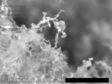
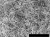
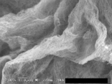
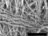
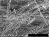
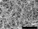
- 6 is an image showing an example of a metal-based structure according to Example 1-1.
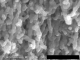
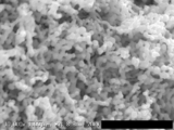
- 6 is an image showing another example of a metal-based structure according to Example 1-1. It is an image which shows another example of the metal type structure which concerns on Example 1-1.
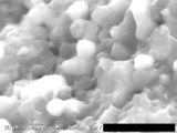
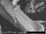
- 10 is an image showing still another example of the metal-based structure according to Example 1-1.
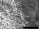
- 6 is an image showing an example of a metal-based structure according to Example 1-2. It is an image which shows an example of the metal type structure which concerns on Example 1-3.
- Example 1-4 It is an image which shows an example of the metal type structure which concerns on Example 1-4.
- 6 is an image showing another example of a metal-based structure according to Example 1-4. It is an image which shows an example of the metal type structure which concerns on Example 1-4-2. It is an image which shows another example of the metal type structure which concerns on Example 1-4-2. It is an image which shows an example of the metal type structure which concerns on Example 1-4-3. It is an image which shows another example of the metal type structure which concerns on Example 1-4-3. It is an image which shows another example of the metal type structure which concerns on Example 1-4-3. It is an image which shows another example of the metal type structure which concerns on Example 1-4-3.
- 6 is an image showing an example of a metal-based structure according to Example 1-5.
- 6 is an image showing an example of a metal-based structure according to Example 1-6.
- 7 is an image showing an example of a metal-based structure according to Example 1-7.
- 6 is an image showing another example of a metal-based structure according to Example 1-7. It is an image which shows another example of the metal type structure which concerns on Example 1-7.
- 10 is an image showing still another example of a metal-based structure according to Example 1-7.
- 10 is an image showing an example of a metal-based structure according to Example 1-7-1.
- 6 is an image showing an example of a metal-based structure according to Example 1-7-3.
- 6 is an image showing an example of a metal-based structure according to Example 1-7-4.
- 6 is an image showing another example of a metal-based structure according to Example 1-7-4.
- 6 is an image showing an example of a metal-based structure according to Example 1-8.
- 10 is an image showing an example of a metal-based structure according to Example 1-9.
- 10 is an image showing an example of a metal-based structure according to Example 1-9-1.
- 6 is an image showing an example of a metal-based structure according to Example 1-9-2.
- 10 is an image showing an example of a metal-based structure according to Example 1-10.
- 3 is an image showing an example of a metal-based structure according to Example 1-11.
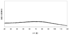
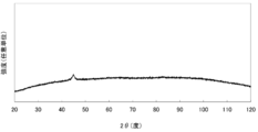
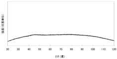
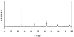
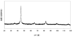
- Example 3 is an image showing an example of a metal-based structure according to Example 1-12-2. It is an image which shows an example of the metal type structure which concerns on Example 1-13. 10 is an image showing another example of a metal-based structure according to Example 1-13. It is an image which shows another example of the metal type structure which concerns on Example 1-13. It is a figure which shows the X-ray-diffraction spectrum of the metal type structure which concerns on Example 1-1 in the Example of this invention. It is a figure which shows the X-ray-diffraction spectrum of the metal type structure which concerns on Example 1-4 in the Example of this invention. It is a figure which shows the X-ray-diffraction spectrum of the metal type structure which concerns on Example 1-4-4 in the Example of this invention.
- FIG. 6 is a diagram showing an X-ray diffraction spectrum of a metal-based structure according to Example 1-7-5 in an example of the present invention. It is a figure which shows the X-ray-diffraction spectrum of the metal type structure which concerns on Example 1-9 in the Example of this invention. It is a figure which shows the X-ray-diffraction spectrum of the metal type structure which concerns on Example 1-10 in the Example of this invention. It is a figure which shows the X-ray-diffraction spectrum of the metal type structure which concerns on Example 1-10-1 in the Example of this invention.
- Metal-based structure (1-1) Structural characteristics (1-1-1) Metal-based structure or nanoparticle
- metal consists of a part of typical elements and transition elements. It means a substance with properties. It can be regarded as a metal due to the following properties. It is a solid at normal temperature and pressure (excluding mercury), has a ductility, a metallic luster, a good electrical and thermal conductor, and a cation (cation) in an aqueous solution.
- Specific examples of the “semimetal” include B, Si, Ge, As, Sb, Te, Se, Po, At, C, and P.
- a semimetal has a property between a metal and a nonmetal, and Ge, Sb, and Po may be classified as a metal.
- Intermetallic compound means a compound of a combination of metal and metal or metalloid.
- Metal compound means a compound containing a metal and a combination of metal and metal, or a combination other than metal and metalloid. Specific examples include metal oxides and metal nitrides. An alloy or intermetallic compound composed of a mixture of a plurality of metal elements or metalloid elements is regarded as one form of metal.
- Metal-based refers to a material containing “metal” as a main component, but may contain a non-metallic component.
- Metal-based structure or nanoparticle refers to a structure or nanoparticle mainly composed of metal.
- structure also includes “nanoparticles”.
- a metal-based structure according to an embodiment includes at least one of the following features (i) to (iv): (I) containing 0.01% by mass or more of hydrogen based on the total mass of the metal-based structure; (I) containing 0.41 atomic% or more of hydrogen based on the total mass of the metal-based structure; (Iii) containing an amorphous phase; and (iv) an X-ray diffraction spectrum showing the presence of a metallic phase in a state where the metallic structure contains an amorphous phase and the metallic structure is heated and crystallized. Is obtained.
- the measurement principle of the hydrogen content in the metal-based structure is based on JIS Z2614.
- the apparatus can perform measurement using the apparatus described in JIS H1619 “Titanium and titanium alloy-hydrogen determination method”. Specifically, a case where measurement is carried out with hydrogen in the apparatus described in JIS H1619 “Titanium and Titanium Alloy—Hydrogen Determination Method 5 Inert Gas Melting—Thermal Conductivity Method” is exemplified.
- An example of a specific measuring apparatus is “EMGA 621A type” manufactured by HORIBA.
- the outline of the measurement method can be as follows. That is, in an inert gas stream, a graphite crucible is used to heat and melt a sample together with tin in an impulse furnace, and hydrogen is extracted together with other gases. The extracted gas is passed through a separation column as it is to separate hydrogen from other gases, which is led to a thermal conductivity detector, and the change in thermal conductivity due to hydrogen is measured.
- the unit of hydrogen content contains Fe or Ni, Co, which is a ferromagnetic material, mass% (in this specification, “wt%” may be described). Is a simple determination method and effective. Further, it can be applied to all other cases.
- atomic% (which may be described as “at%” in the present specification) is effective in the case where it is essentially controlled in principle. It is also possible to manage by direct counting of the number of atoms), which is relatively excellent.
- the metal-based structure to be measured is a single phase, it is possible to convert from mass% to atomic% strictly, but if the metal-based structure is a multiphase, the composition ratio is It cannot be converted without seeking. In the case where the metal-based structure is a double phase, the composition ratio is obtained by another method (ICP or the like) and then converted.
- the metal-based structure By containing 0.001% by mass or more of hydrogen with respect to the entire metal-based structure, the metal-based structure becomes less susceptible to oxidation and is excellent in adhesion and sinterability.
- the hydrogen content is more preferably 0.010% by mass or more, and further preferably 0.20% by mass or more.
- the metal structure By containing 0.41 atomic% or more of hydrogen with respect to the entire metal structure, the metal structure is less susceptible to oxidation and has excellent adhesion and sinterability.
- the hydrogen content is more preferably 5.04 atomic% or more, and further preferably 5.5 atomic% or more.
- the metal-based structure contains hydrogen, and the hydrogen content is 0.41 atomic% (0.01% by mass) or more, preferably based on the total mass of the metal-based structure. Is 3.03 atomic% (0.056 mass%) or more, more preferably 5.3 atomic% (0.10 mass%) or more, and still more preferably 10.1 atomic% (0.20 mass%) or more.
- the hydrogen-containing metal-based structure or the hydrogen-containing amorphous body stably has an amorphous portion and stably forms or maintains the purity of the metal element of the metal-based structure. It is effective for producing a crystallized metal phase and a high-purity metal structure after heat treatment.
- the metal-based structure contains hydrogen, and further contains hydrogen of a specified value or more and / or has an amorphous part, so that the metal-based structure does not contain a nucleating agent.
- Manufacture is possible, whereby various shapes can be precisely formed, which is preferable from the viewpoint of high purity.
- this hydrogen-containing amorphous exhibits an excellent effect in controlling the shape of the metal-based structure. It is also effective in forming an amorphous phase.
- the upper limit of the hydrogen content of the metal structure is not particularly limited.
- the hydrogen content of the metal-based structure is preferably 50 atomic percent or less, 25 atomic percent or less or less than 25 atomic percent, further 23 atomic percent or less, or less than 23 atomic percent, further 20 atomic percent or less, or In some cases, it may be more preferable that the content is less than 20 atomic%, further 16.4 atomic% or less or 16.4 atomic%, further 13 atomic% or less or less than 13 atomic%.
- the hydrogen includes diffusible hydrogen and non-diffusible hydrogen.
- diffusible hydrogen refers to hydrogen that is present in a material and exits (diffuses) out of the material over time at room temperature.
- Non-diffusible hydrogen refers to hydrogen that exists in a material and cannot escape (do not diffuse) from the material with time even at temperatures from room temperature to about 200 ° C. Diffusible hydrogen is thought to contribute to hydrogen embrittlement.
- the hydrogen that does not go out of the metal structure when the metal structure of the present invention is heated at 200 ° C. for 2 minutes is non-diffusible hydrogen.
- the amount of hydrogen in each state can also be measured by a temperature programmed desorption analyzer (TDS). This is the same whether the metal-based structure is in an amorphous phase or crystallized.
- the hydrogen content when heated at 200 ° C. for 2 minutes is preferably 0.01% by mass or more or 0.41 atomic% or more based on the total mass of the structure, or 0.056% by mass or more, It is more preferably 3.03 atomic% or more, even more preferably 0.10 mass% or 5.3 atomic% or more, and 0.20 mass% or more or 10.1 atomic% or more. Further preferred.
- Amorphous phase means that there is no long-range order in the portion, and there is no crystal in the X-ray diffraction spectrum. This is a phase in which no prominent peak derived from the structure exists.
- the metal-based structure includes an amorphous part or an amorphous part containing hydrogen, plastic deformation or the like is likely to occur, and the sinterability and adhesion are excellent. From the viewpoint of excellent sinterability and adhesiveness, the metal-based structure is preferably an amorphous single phase. In addition, being amorphous makes it a magnetically and mechanically superior material by bringing magnetic and mechanical isotropy to the metal-based structure.
- an amorphous structure containing hydrogen and further containing hydrogen of a specified value or more has excellent shape controllability of a metal-based structure (magnetic field alignment, adhesion, and shape anisotropy). And the formation of an amorphous phase). That is, when the metal-based structure contains hydrogen and / or when the metal-based structure includes an amorphous part, the deformability and stickiness of the metal-based structure, the nanostructure, and the nanoparticles are reduced. Due to the improvement effect, it becomes easy to form various shapes as the entire structure. This tendency becomes remarkable in the liquid and further in the liquid containing the hydrogen-based substance.
- the metal-based structure includes an amorphous part
- an X-ray diffraction spectrum indicating the presence of the metal phase is obtained in a state where the metal-based structure is heated and crystallized.
- the X-ray diffraction spectrum of the metal structure obtained in a state in which the metal structure is heated and crystallized may be a spectrum indicating that the metal structure is a metal single phase.
- the metal single phase is a phase made of only metal, and means a phase that does not contain a phase other than a metal phase such as an oxide. It is composed of an element selected from metal elements and / or metalloid elements, and examples include metal element single phases, alloys, metalloids, intermetallic compounds and their solid solutions, and mixtures and composites of these.
- the reason why the metal-based structure according to an embodiment of the present invention includes an amorphous part is considered as follows.
- the hydrogen in the metal structure has an influence on the formation of the amorphous part, that is, the hydrogen is contained in the metal structure, which prevents the metal reductant from crystallizing during growth. As a result, it can be said that a region in an amorphous state or a state close thereto is generated in the metal-based structure.
- the X-ray diffraction spectrum of the metal-based structure has substantially no peak, and the entire structure can be considered to be amorphous, that is, amorphous. It is possible to obtain a single-phase metal-based structure. As will be described later, in an embodiment according to the present invention, a metal-based structure having an amorphous single phase and containing hydrogen is obtained. From this result, it is confirmed that the amorphous part is a hydrogen-containing amorphous. I understand. Such amorphous and hydrogen-containing amorphous phases are bonded to each other between metal-based structures or between nano-part structures constituting the metal-based structure for reasons such as high plastic deformation and bonding. It can be said that it is easy.
- the metal structure which gives the X-ray diffraction spectrum shown in FIG. 42 is one in which the reductant is Fe, and no peak derived from the crystal structure is observed.
- the metal-based structure is heated, as shown in FIG. 43, a crystallized metal-based structure is obtained in which only a peak attributed to ⁇ Fe having a body-centered cubic lattice structure is substantially obtained in the X-ray diffraction spectrum. be able to. From this, it is understood that in the state before heating, the metal-based structure was mainly an amorphous portion mainly composed of Fe single element metal.
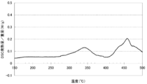
- the DSC (differential) when the metal structure manufactured by the same method as that of the metal structure having a filament web shape shown in FIG. 32 was heated to 500 ° C. (temperature increase rate: 3 ° C./min).
- the result of the scanning calorimeter is as shown in FIG. It can be said that the heat generation having a peak at around 460 ° C. is based on crystallization. It can be said that the chemical change or state change that gives an exotherm having a peak at around 320 ° C. is caused by a structural change accompanied by a crystallographic and / or chemical change.
- the metal-based structure according to the present invention can be made of a single element metal. It is known that an amorphous phase of a single element metal (pure metal) can be made by a vacuum deposition method at an extremely low temperature. In the vacuum deposition method, it was the first time that Bi was successful, and thereafter, it was also made of Ga, Fe, Ni, Cr, Au, and the like. However, both are unstable and crystallize below room temperature. Therefore, what is generally called an amorphous metal (amorphous metal) is an alloy.
- an amorphous phase of a single Fe element that is stable at room temperature has not been confirmed.
- the Fe 2 B composition there is an amorphous formation example, and it has been put into practical use.
- the known Fe 2 B amorphous material is obtained by a rapid solidification method, and a ribbon-like amorphous material can be obtained by rapidly cooling the dissolved FeB to room temperature.
- an amorphous phase made of a single element metal can be created.
- an amorphous phase of Fe containing hydrogen was stably obtained. From this, it is considered that an amorphous phase was formed by containing hydrogen.
- the mechanism of this amorphous formation is the formation of a crystal structure of Fe by forming a previously unknown bond reaction state between Fe and hydrogen, which is a combination with a very low reactivity. It is considered that an amorphous phase was formed by inhibiting the formation.
- the self-granulation reaction is simply set reaction conditions and left to stand. It means that formation of a particle shape proceeds and particles having a specific shape, structure (amorphous structure), composition, and hydrogen content are formed.
- the reduction precipitation reaction by the two-liquid mixing method described later by suppressing the mechanical external force to the precipitation particles by stirring operation etc. as much as possible (control without inhibiting the progress of the self-granulation reaction) This is the case (see the examples).
- the driving force that forms and maintains a specific amorphous structure is presumed to be a magnetic property of the entire particle. It is presumed that the influence of the size for forming the single domain structure is large. Amorphous amorphous structure is formed at the initial stage of deposition, and the particle is grown by the surface energy driving force to increase the particle size. Magnetically stable particle size, for example, magnetic energy based on single domain structure is minimal. The particle growth is suppressed at the particle size. Thereby, it is considered that amorphous particles having a specific particle diameter with uniform particle diameter are formed. The mechanism by which specific amorphous structures are created in the early stages of precipitation will be due to natural selection. It is presumed that only particles with an amorphous structure having a specific structure grow, and those that do not grow into a relatively unstable state due to the growth and stop or disappear.
- the factors that determine the state of particles are the energy and surface energy based on the magnetic properties of the particles, and also the amorphous structure and size. (For example, the particle size when spherical is assumed).
- the particle size when spherical is assumed.
- there are two types of stable amorphous magnetic particle states (amorphous structure and size), which are separated by the metal ion concentration. It is presumed that a self-granulation reaction takes place with the change to the stable state as a driving force.
- the metal-based structure according to the present invention may be composed of a magnetic body.
- magnetic material refers to a material that is magnetized in a magnetic field.
- the material constituting the magnetic material include metals, metalloids, intermetallic compounds, metal compounds, borides, phosphides, sulfides, and oxides.
- metals, intermetallic compounds, and metal compounds are preferable, and those containing a transition (metal) element are also preferable.
- those containing a ferromagnetic element Fe, Ni, Co, Gd, etc.
- the magnetic properties may be different from bulk bodies that are large lumps.
- the metal-based structure may be a structure obtained by reduction in a liquid as described later.
- the “liquid” may be a solution or a dispersion.
- the liquid is preferably a solution. That is, it is preferable that at least a part of the reducible substance is dissolved in the liquid.
- This liquid may be free of nucleating agents including substances that are preferentially reduced over reducible substances.
- the nucleating agent is reducible by the action of promoting the precipitation of the reducible substance, for example, by forming fine particles by being reduced preferentially over the reducible substance. It is added to act as a nucleus for forming fine particles and fine structures made of a substance.
- a substance that can form a reducing substance (such as a metal) by a reduction reaction, such as a reducible substance, is present in the liquid, and in addition to the reducing agent, a substance that becomes a crystal nucleus (for example, It is also possible to form a nanoparticle by precipitating and growing a reducing substance from a reducible substance using a component based on the nucleating agent as a nucleus and depositing and growing a reducing substance from the reducible substance. It is generally performed from the viewpoint of stably forming the film.
- a component based on the nucleating agent is necessarily contained in the nanoparticle, and the metal-based structure formed from the nanoparticle has a compositional problem.
- the degree of freedom is reduced.
- such a component may restrict the magnetic characteristics and mechanical characteristics of the metal-based structure. Therefore, when reducing a reducible substance, the liquid does not contain a nucleating agent, so that the degree of freedom in composition of the metal-based structure can be increased, and the range of possible magnetic properties and mechanical properties can be increased. Can do.
- the precision of form control can be enhanced by these effects and high-purity metal-based structures.
- the above liquid does not need to use a nucleating agent containing a substance having a smaller ionization tendency than a reducible substance.
- the liquid does not need to use a nucleating agent containing a metal or metalloid element other than the reducible substance.
- the liquid may not use a nucleating agent.
- the metal-based structure according to the present invention may not contain a nucleating agent.
- the hydrogen content of the metal-based structure of the present application was confirmed to be a blending ratio “specific blending ratio” according to a special rule.
- specific blending ratio In order for the metal-based structure to have a “specific blending ratio”, smaller structures are formed with the same blending ratio, so that the structure and blending ratio are stably formed.
- aggregates or clusters of precipitated particles and nanoparticles formed by aggregation of the particles are stably formed with a specific mixing ratio.
- the reason for the specific blending ratio is understood by the formation of a “shell structure” or a “regular polyhedral structure” precipitate aggregate or “H cluster”.
- a metal element and further a metal single element (Fe) it conforms to the regular polyhedron rule. From this, the presence of an aggregate or cluster consisting of a regular polyhedral structure or a structure having the same blending ratio (atomic ratio) was specified.
- the “H cluster” composed of metal atoms and hydrogen which is the cluster of the present application, is an aggregate of metal atoms and hydrogen, and has a mixing ratio of m: 1 (m is an integer, m ⁇ 3). This further aggregates to form nanoparticles and metal-based structures. Furthermore, a nanostructured compact such as a nanowire is formed. 3 ⁇ m (upper limit is preferably in the range of m ⁇ 300). Hydrogen content (lower limit is preferably 300 to 0.33 at% of upper limit of m number) to 25 at% (corresponding to 3 ⁇ m) Configured by range.
- m number becomes a discrete value due to the limited type of bonding state between H and metal atoms.
- a jumping number is called a “magic number” and is known as a phenomenon in which a special number of structures exist stably in a nuclear structure or a metal cluster structure.
- Na metal clusters are known to exist stably at 8, 20, 40, 58, 92, 138, 198, 264, 344, 442, 554, and even larger numbers of atoms.
- the H number of the H cluster varies depending on the mixing ratio of metal atoms and hydrogen.
- the metal-based atom is a metal element, and further when it is a metal single element (Fe), it conforms to the regular polyhedron rule. From this result, a "regular polyhedral structure" is formed in which hydrogen is arranged in the center and metal atoms are arranged like a shell around it, and the distance from hydrogen is equal and adjacent metal atoms are equal.
- the “regular polyhedron H cluster structure” as the distance is suitable.
- regular polyhedral H clusters made of a single element metal and further made of Fe element as in the embodiment can be stably obtained.
- the “regular polyhedral H cluster structure” includes a cluster structure composed of structures having the same blending ratio. That is, a distorted structure (substantially regular polyhedral structure) is also included. The number of m can be selectively controlled depending on the type of atoms and reaction conditions.
- the H cluster can be more stably formed by the metal bond when the metal element is a transition metal.
- the metal element is a transition metal.
- Fe, Ni, and Co, which are ferromagnetic elements, it may be easy to form shaped nanoparticles by self-granulating reaction.
- m corresponds to the number of metal atoms for one H atom, and in the case of multiple elements, it corresponds to the total number.
- Regular polyhedron rule An arrangement where the distances from the center are equal and adjacent atoms can be equidistant, and atoms are arranged at the apex of the regular polyhedron, the center of the face, and the center of the side (not placed in mixed positions) For example, it is a blending ratio formed by a “regular polyhedral structure” formed by a vertex and a center.
- the number of atoms arranged in the “regular polyhedral structure” is a number selected from 4, 6, 8, 12, 20, and 30.
- M: H m: 1, m is a value selected from 4, 6, 8, 12, 20, and 30.
- H% 3.2 to 20.0 at%. This structure is easy to form when M is a metal element or even a single element metal.
- the metal-based structure has a H% of a specified value or more, and further includes a metal-based structure, nanoparticle, cluster containing a metal element Preferably it consists of.
- the metal element contains the following elements, and further selected from the following element group.
- the transition metal element is an element existing between the Group 3 element and the Group 12 element in the periodic table. Furthermore, there may be a case where an element existing between a Group 3 element and a Group 13 element in the periodic table is preferable. Further, among the transition metal elements, there are cases where the elements present between the Group 3 element and the Group 11 element in the periodic table are more preferable. (3) Among elements (2), an element selected from Sc, Ti, V, Cr, Mn, Fe, Co, Ni, and Cu may be preferable. (4) Furthermore, an element selected from Fe, Co, and Ni exhibiting ferromagnetism may be preferable particularly for forming self-granulating reaction particles. (5) Further, as shown in the examples, Fe is preferable in stable production. In general, Fe has a tendency to be easily oxidized in a solution and is extremely difficult to form by conventional methods. Therefore, the production method of the present application is particularly preferable from the viewpoints of production stability and performance reliability.
- the metal-based structure according to an embodiment of the present invention may have a granular body having a size exceeding at least 1 nm as either a partial structure or an entire structure.
- the partial structure of the metal-based structure has a size exceeding at least a certain length (1 nm in the above case) means that the metal-based structure is inside a sphere whose diameter is the length. This means that the entire partial structure cannot be included. Specifically, when observed with a secondary electron microscope, this means that the partial structure necessarily has a portion that does not fit in a circle having a certain length as a diameter.
- a metal-type structure which concerns on one Embodiment of this invention makes said granule the whole structure
- a metal-type structure consists of the granule.
- a metal-based structure having a whole structure of a granular body having a bead-like shape, which will be described later, can be cited.
- a metal-based structure according to an embodiment of the present invention has a nano-part structure that is a partial structure having a portion having a size of less than 1 ⁇ m at the maximum that can be identified by a secondary electron image when observed with an electron microscope. And may have a size exceeding 10 ⁇ m as a whole.
- a partial structure having a portion having a size of less than 1 ⁇ m at the maximum means that when a virtual sphere having a diameter of 1 ⁇ m is superimposed on a metal structure, the inside of the sphere is overlapped. It means a structure that can find the characteristics of a partial structure.
- the metal-based structure including a nanopart structure according to an embodiment of the present invention may specifically have the following shape.
- the amorphous phase containing hydrogen according to the present invention is an amorphous phase, it is presumed that the following shape is due to the above-mentioned self-granulation reaction.
- the metal-based structure including a nanopart structure according to an embodiment of the present invention may have a wire shape (filament shape or filament yarn shape).
- the “filament” is a term corresponding to a long fiber in the field of fibers
- the “filament yarn” means a filament formed by spinning the long fiber.
- the observed metal-based structure has a thread-like shape, and has an aspect ratio of 5 or more, which is a ratio of the longest axis length to the shortest axis length, and the metal-based structure.
- the metal-based structure is called a filament.
- the axial length of the shortest axis is less than 1 ⁇ m.
- the metal-based structure is composed of nano-part structures having an aspect ratio of 5 or more and having a plurality of thread-like shapes
- the metal-based structure is called a filament yarn.
- FIGS. An example of an observation image of a metal-based structure having such a filament or filament yarn shape is shown in FIGS.
- anisotropy means that the physical properties of a substance vary depending on the direction
- shape anisotropy means a shape that is biased in any direction.
- the average minor axis length of the wire-like structure is preferably 50 to 250 nm.
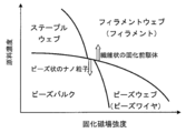
- the metal-based structure according to an embodiment of the present invention may have a web-like shape formed from the metal-based structure having the filament yarn-like shape described above. Good.
- the metal-based structure having the web-like shape is referred to as a filament web.
- the “web” is as defined in the field of fibers, and is a collection of fibers, and means a three-dimensional member obtained by tangling or binding fibers at a plurality of points.
- the nano-part structure constituting the metal-based structure having a filament web shape is a filament. Accordingly, the filament web is a metal-based structure having a partial structure having anisotropy in shape.
- FIG. 12 An example of an observation image of a metal-based structure having such a filament web shape is shown in FIG. 12 that a plurality of filaments are bound or entangled to form a three-dimensional member.
- a plurality of filaments constituting the web are arranged apart from each other, so that a void portion exists. Therefore, such a filament web has a shape that can function as a three-dimensional mesh. That is, in this case, the metal-based structure according to one embodiment of the present invention includes a partial structure having a mesh shape (FIGS. 13 to 15).
- the metal-based structure according to an embodiment of the present invention is not composed of a metal-based structure having a particularly high aspect ratio, such as a filament web, It may have a web-like shape having a three-dimensional network structure. An example of an observation image of a metal-based structure having such a shape is shown in FIG.
- the metal-based structure having the web-like shape is close to the shape obtained by entanglement of a plurality of short fibers (staples). Therefore, in this specification, such a web-like shape is used. Is called a staple web.
- the nano-part structure constituting the metal-based structure having the shape of a staple web is a staple. Since this staple has a nano-part structure, the axial length of the shortest axis is less than 1 ⁇ m. Accordingly, the staple web is a metal-based structure having a partial structure (staple) having anisotropy.
- a metal-based structure according to an embodiment of the present invention has a bead wire-like shape composed of a plurality of bead-like (spherical) nanopart structures. May be.
- “bead” means a nano partial structure having a shape with an aspect ratio of less than 2. Therefore, in the present specification, “staple” means that the anisotropy is higher than “bead” and less than “filament”, and in this specification, “bead wire” means a nanoparticle having a bead-like shape.
- FIG. 10 An example of an observation image of a metal-based structure having such a bead wire shape is shown in FIG. Many metal-based structures having a bead wire shape having a length of 10 ⁇ m or more have been observed.
- FIG. 37 is an observation image obtained by enlarging a part of FIG. 36.
- 37 are aligned to form a linear body. Specifically, one bead is connected to one bead in the longitudinal direction. It seems that beads were fixed one by one in one direction. According to FIGS. 36 and 37, the aspect ratio of the bead wire far exceeds 5.
- the average length of the bead-like (spherical) particle structure is preferably 150 to 500 nm.
- a metal-based structure according to an embodiment of the present invention has a three-dimensional shape obtained by binding or intermingling a plurality of the above-described bead wires. It may be. Such a shape is referred to herein as a “bead web”.
- the metal-based structure having a bead web-like shape is composed of a nano-part structure having a bead wire-like shape. Therefore, the bead web is a metal-based structure having a partial structure (bead wire) having anisotropy.
- 36 to 38 are also examples of observation images of a metal-based structure having such a bead web-like shape.
- FIG. 36 is an enlarged view of a part of FIG. In the metal-based structure having a bead web-like shape shown in FIG. 36, a plurality of metal-based structures having a bead wire-like shape constituting this are bundled while being oriented.
- the metal-based structure according to FIG. 16 which is another example of the observation image of the metal-based structure having such a bead web-like shape, constitutes a bead web as compared with the metal-based structure shown in FIG.
- the length of each individual bead wire is short, resulting in a large degree of bead wire entanglement.
- the metal-based structure having a bead web shape has a shape that can function as a three-dimensional mesh. That is, in this case, the metal-based structure according to an embodiment of the present invention includes a partial structure having a mesh shape.
- the metal-based structure according to an embodiment of the present invention has a particularly low degree of connection between a plurality of nano-part structures having a bead-like shape while being aligned with each other.
- the nano partial structure may have a shape formed by isotropic bonding.
- such a massive shape composed of a plurality of bead-shaped nano partial structures is also referred to as a “bead bulk”.
- FIG. 20 is also an example of an observation image of a metal-based structure having a bead bulk shape.
- Average length of particle structure or average diameter of particle structure when particle is spherical is It can be determined from the average value of the short axis length d of the filament, staple, bead wire, and bead bulk.
- the metal-based structure was based on a staple or filament shape, particles with a uniform size of 110 to 150 nm (referred to as 100F) were observed.
- 100F preferably has a particle size of 50 to 250 nm, more preferably 50 to less than 175 nm, and even more preferably 100 to less than 175 nm.
- the amorphous phase is an amorphous phase, and (a) high fixability (b) has a high filling capacity and forms a filled phase. A state with a high hydrogen content is particularly effective.
- FIG. 20 consists of roughly 300 nm particles that appear white and an amorphous phase.
- a thin whiskers that look white are observed. This is because, for example, the tip of the wavy fracture surface that is observed when the glass is put between two pieces of glass and then peeled off is observed as white whiskers. This is because the convex part is observed in white.
- the structure which consists only of an amorphous phase is observed. From this, as shown in FIGS. 20 and 21, due to the amorphous phase being an amorphous phase and a particularly high H content, the adhesiveness between the amorphous phases is high, Further, it can be seen that the filling ability to fill the voids is high, thereby forming a dense solid body substantially free of voids. Further, even after crystallization by heat treatment, as shown in FIG. 25, a dense solid body (sintered body) that is an aggregate of nanoparticles and substantially free of voids is obtained. This has a great effect that a solid body substantially free of voids is formed in the solidified body before heat treatment as shown in FIGS. From this, it can be seen that the amorphous phase is highly effective in densifying the sintered body.
- FIG. 22 is an image obtained by observing a metal structure cooled to room temperature after heat treatment under heat treatment condition 1 held at 50 ° C. for 2 minutes.
- the shape of the bead-shaped nanopart structure constituting the bead bulk can be easily confirmed individually, and it can also be confirmed that there are many voids between the beads.
- the observation image by the secondary electron microscope is transparent.
- the amorphous phase observed as semi-transparent is generated so as to surround the entire bead-like nanopart structure constituting the bead bulk, and as a result, the voids of the metal-based structure are filled with the amorphous phase, A dense solid body having substantially no or very few parts is formed.
- the metal-based structure according to an embodiment of the present invention has an amorphous structure that fills at least a part of a void defined by a plurality of bead-like nanopart structures. It may further have a phase.
- the metal-based structure according to an embodiment of the present invention may have an amorphous phase that exists so as to disperse a plurality of bead-like nanopart structures therein, as shown in FIG.
- the metal-based structure according to an embodiment of the present invention may have both of these two forms related to the amorphous phase. That is, as shown in FIG. 20, bead-like nanoparticulate structures are dispersed inside the amorphous phase, and some of the bead-like nanoparticulate structures are connected to each other. An amorphous phase may be present so as to fill a void defined by the partial structure. Furthermore, as shown in FIG. 21, the amorphous phase may exist so as to be substantially a single phase.
- the amorphous phase is not observed only in a metal-based structure having a bead-like nano-part structure, and is not observed for the first time when the metal-based structure is heated.
- an amorphous phase can be observed even in a metal-based structure having a staple web shape.
- the metal-based structure having a staple web shape according to FIG. 5 was observed after being taken out from the liquid and not subjected to any special heat treatment, and dried at room temperature. Therefore, in some cases, the amorphous phase can be observed without any heat treatment.
- the composition of the amorphous phase is not always clear. However, it is observed that there is a large amount of amorphous phase when the hydrogen content in the metal-based structure is high. In this case, it is considered that hydrogen is contained in the amorphous phase. And it is thought that this hydrogen is suppressing that the metal type substance contained in a metal type structure is oxidized.
- the metal-based structure according to an embodiment of the present invention may include an amorphous portion.
- a metal-based structure FIG. 9
- FIG. 9 A result showing that the structure is highly amorphous is obtained.
- the threshold of the amorphous phase can be summarized as follows. (1) An amorphous phase is formed by setting the content of hydrogen contained in the metal-based structure to 0.41 atomic% (0.01% by mass) or more. (2) The content of hydrogen contained in the metal-based structure is 2.7 atomic% (0.05 mass%) or more, preferably 5.3 atomic% (0.10 mass%) or more, more preferably 10 When the content is 1 atomic% (0.20 mass%) or more, an amorphous phase is easily formed. (3) An amorphous phase is formed by setting the content of the reducible substance to 0.3 mmol / kg or more with the saturation concentration as the upper limit.
- the lower limit is 0.3 mmol / kg, less than 150 mmol / kg, preferably less than 60 mmol / kg, more preferably less than 15 mmol / kg, the amorphous phase is easily formed. Furthermore, by setting the lower limit to 1 mmol / kg, the amorphous phase is more stably formed. (4) By containing alcohol in the solvent, an amorphous phase is easily formed.
- the metal-based structure contains a ferromagnetic material, particularly Fe, an amorphous phase is easily formed when the above conditions (3) and (4) are satisfied.
- This cluster structure is the smallest structural unit such as a compound molecule, and its composition and structure are determined. Crystal growth does not occur, and when an amorphous nanoparticle is formed by forming an aggregate of clusters. By thinking, consistency with the experimental results can be obtained. That is, it is reasonably understood that amorphous nanoparticles having a uniform composition, structure, and physical properties are formed by an assembly of cluster type compounds.
- the uniform shape and size of amorphous nanoparticles is due to the self-regulating granulation reaction (self-granulation reaction) occurring in the process of clustering due to the magnetic properties and surface effects of nanoparticles. It is assumed that a stable shape and size were formed.
- Amorphous particles are basically amorphous. In the case of an amorphous substance that does not contain hydrogen, it is easy to oxidize, so it is broken by stirring and the surface is oxidized to form particles or cannot aggregate more than a certain size from the beginning-oxidation progresses during aggregation Thus, particles are formed by a mechanism (that is, oxidation) such that the two cannot be fixed to each other. In other words, in the case of an amorphous material that does not contain hydrogen, particles are not formed but oxidized, so that an amorphous phase that is a large aggregate cannot be formed. When stirring, it is like mechanically pulverizing, and the size of the pulverized particles is equalized by making the pulverization conditions constant.
- the amorphous phase component forms an agglomerate or forms an amorphous phase (an agglomerate of several hundred nm or more) by entering a gap between particles.
- both the regular dodecahedron cluster and the regular hexahedral cluster are both short-range ordered clusters and the aggregate is amorphous. (No long-range order is formed). This is derived from the experimental fact that the metal composition is controlled to be a single element, but an amorphous state is formed as a whole by containing a high amount of hydrogen.
- this cluster forms nanoparticles of about 100 nm (hereinafter referred to as “100F”), and the growth is self-contained.
- 100F the particles having a size of 100F are formed by self-control of the shape and size of the aggregate by its own magnetism--the growth is stopped by becoming a magnetically stable shape.
- a wire structure in which 100Fs are aligned in a magnetic field is shown in FIG.
- this cluster forms nanoparticles of about 300 nm (hereinafter referred to as “300B”), and the growth is self-contained.
- 300B 300 nm
- 100F alignment is performed in a magnetic field to form a bead wire (FIG. 27).
- the amorphous phase is formed by whether 300B collapses (decay factor) or whether an amorphous phase is formed without forming 300B (aggregation inhibition factor).
- the amorphous phase and 300B are composed of the same thing (regular hexahedral cluster), and the shape of the amorphous nanoparticles changed in a transitional manner because the conditions of the example are transitional conditions ( (Standard / amorphous).
- FIG. 20 a phase in which 300B and an amorphous phase are mixed is formed.
- FIG. 21 it is a substantially amorphous phase.
- the beads are aligned and fixed by applying a magnetic field to form a bead wire, and an amorphous phase cannot be confirmed, and only the beads (300B) are present.
- This bead-only form is also an amorphous single phase after drying (FIG. 44), and after heat treatment is an ⁇ Fe single phase from the result of XRD (Example 1-9-3), and contains an amorphous phase. Since it has the same structural change and composition as 20, 300B and the amorphous phase are both amorphous and have the same composition (Fe single phase).
- the reason why only the beads are obtained by applying the magnetic field seems to be that the particles were selectively assembled by the magnetic field and bound in the form of bead wires.
- the amorphous phase may have been abandoned in the washing process because the magnetic field is a little weak and difficult to collect, or it is susceptible to solvent resistance and is difficult to collect.
- the shape of the beads is stabilized by the action of the magnetic field, that is, the shape is not easily collapsed by the action of the magnetic field.
- the amount of the amorphous phase varies depending on the drying temperature (heat treatment temperature).
- an amorphous phase is formed by staples in a condition where ethanol is added to the solvent. Addition of ethanol to the solvent hinders cluster assembly and inhibits the formation of shaped particles and forms an amorphous phase (assembly inhibition factor), or addition of ethanol to the solvent changes the cluster structure. It is thought that the hydrogen content increased.
- a crystallized metal structure having a crystal phase in at least a part according to an embodiment of the present invention includes the above metal structure. It can be obtained by crystallization by heating or the like.
- the conditions for crystallization are appropriately set based on the structure and composition of the metal-based structure. For example, in the metal structure shown in FIG. 32 having Fe as a metal reductant and having a filament web shape, it is considered to be based on crystallization at 500 ° C. or lower as shown in FIG. Has an exothermic peak.
- a metal-based structure according to an embodiment of the present invention is heated beyond the crystallization temperature, a structure in which the volume of the void portion defined by the nanopart structure is reduced or a structure in which the void portion is substantially extinguished. In some cases, a crystallized metal-based structure having the following can be obtained.
- FIGS. 24 and 25 are examples of observation images of a bead bulk metal structure heated to 400 ° C.
- FIG. 43 shows an X-ray diffraction spectrum of the metal structure obtained by heating to 600 ° C. It is an example.
- the bead bulk metal structure is a structure having an amorphous phase after heat treatment at 200 ° C. as shown in FIGS.
- FIG. 25 is an enlarged view of a part of FIG. 24. Nanoparticles in which voids are substantially absent or extremely small as crystallization and sintering proceed by heating to 400 ° C. It can be seen that a dense solidified body is formed. Further, from the result of FIG. 43, it is observed that a structure composed of a high purity metal phase ( ⁇ Fe) is formed.
- ⁇ Fe high purity metal phase
- FIG. 35 is an example of an observation image of a bead bulk metal structure heated to 600 ° C.
- FIG. 50 is an example of an X-ray diffraction spectrum of the metal structure obtained by heating to 600 ° C.
- FIG. 33 and FIG. 34 are examples of observation images of a bead bulk metal structure heated from 150 ° C. to 200 ° C.
- the bead-like nanopart structures are connected approximately isotropically, and an amorphous phase is formed. It is observed that there are very few metal-based structures.
- FIG. 35 it can be observed that the voids are reduced by crystallization and sintering by heating to 600 ° C., but there are many voids in the structure composed of nanoparticles. is doing. Further, it is observed from the results of FIG. 50 that an Fe 2 B intermetallic compound single phase is formed.
- the presence of the amorphous phase and / or the metal-based structure contains hydrogen, and the hydrogen content is 0.4 atomic% (0.01% by mass) or more. 2.7 atomic% (0.05% by mass) or more and / or when the metal-based structure contains an amorphous part, a solidified body composed of nanoparticles is formed, and further high purity. With a metal-based structure, it becomes easy to form a dense solidified body made of nanoparticles.
- FIG. 27 is an example of an observation image of a metal structure having a bead web-like shape heated to 250 ° C., and a metal system obtained by heating the metal structure shown in FIG. 27 to 600 ° C.
- An observation image of the structure is shown in FIG. It can be seen that as the crystallization and sintering proceed, the diameter of the nano-part structure having a bead-like shape increases, and the volume of the void defined by the nano-part structure decreases.
- the crystallized metal-based structure obtained from the metal-based structure according to one embodiment of the present invention may have an X-ray diffraction spectrum that is understood to be composed of a single phase of metal.
- the metal-based reductant reduced from the reducible substance is Fe
- the metal-based structure is substantially amorphous
- the crystallized metal obtained by heating it From the system structure an X-ray diffraction spectrum having an ⁇ Fe single-phase peak is obtained (FIG. 65).
- Fe single-phase peak is obtained is obtained (FIG. 65).
- the reason why such a single-phase material is obtained is that the metal-based structure according to one embodiment of the present invention contains hydrogen, and when the metal-based structure is heated to crystallize, the hydrogen is a metal. This is probably because the oxidation of the metal-based reductant contained in the system structure is suppressed.
- a composite structure according to an embodiment of the present invention includes the metal-based structure as a part thereof.
- the content ratio of the metal structure in the composite structure is not particularly limited.
- the metal structure may be more dominant in the composite structure.
- another material also referred to as “additional substance” in this specification
- the additional substance may be fixed to the metal-based structure. Examples of specific means for fixing include heating and pressurization.
- the specific composition and structure of the additional substance are not particularly limited as long as at least one of the composition and the structure is different from that of the metal-based structure. Taking the case where the metal-based structure has Fe as a reductant, for example, an additive substance composed of a catalyst such as platinum, a tungsten powder, and a ceramic powder is exemplified.
- the content ratio of the metal-based structure in the composite structure may be smaller than the content ratio of the additional substance.
- Specific examples of such a case include a sintered material using a metal-based structure as a sintering aid and a resin-based material obtained by dispersing the metal-based structure therein.
- the composite structure may include the crystallized metal structure as a part thereof.
- Such a composite structure may be obtained by adding an additional substance to the crystallized metal-based structure, or crystallize the metal-based structure of the composite structure including the metal-based structure as a part thereof. May be obtained.
- you may obtain by fixing metal type structures. Further, by heating and / or pressurizing, the partial structures inside the metal-based structure that reduce the volume of the voids of the metal-based structure can be fixed.
- the present application provides a metal-based structure containing hydrogen of a specified value or more, thereby stably imparting the adhesiveness and formability of the metal-based structure, and in particular nano-size. These particles have a great effect on the stability and safety of their physical properties. Furthermore, the effect is particularly great in controlling the formation of a secondary structure constituted by an aggregate of nanoparticles. In addition to containing hydrogen, it contains an amorphous phase, or contains an amorphous phase containing hydrogen, and further contains an amorphous phase formed by containing hydrogen. Found that the moldability was further improved.
- metal-based structures contain hydrogen, and further contain hydrogen beyond the normal content range, that is, contain hydrogen beyond the saturation concentration of hydrogen solid solution in a specific state (temperature, pressure). In addition, it was impossible or extremely difficult to form an amorphous state by containing hydrogen. The reason is that high hydrogen content control like this application was not able to be performed by the normal method.
- the normal method is to increase the hydrogen content by increasing the hydrogen gas pressure in the environment where the material is placed or by increasing the saturation concentration by increasing the temperature, or in the reduction reaction, for example, containing hydrogen.
- the increase in the hydrogen content does not occur or is extremely difficult, the hydrogen content cannot be controlled as in the present application, and the hydrogen-containing body as in the present application cannot be produced.
- the control factors in the reductive precipitation reaction by mixing two liquids in the liquid used in this application are largely “solution control” and “reaction environment control”.
- the former factors are (1) reducing agent, (2) possible There are reducing substances, (3) solvent, and (4) “reaction environment control” and 4 points are the main ones.
- (1) is the above-mentioned direct control method, but even if this factor is controlled, the special hydrogen content control as in the present application cannot be practically performed.
- (2) to (4) the hydrogen concentration in the mixed solution does not change directly, and is a control condition that cannot be seen at first glance when assuming a normal reaction state.
- the control of the hydrogen content is realized by the following method by manipulating the control factor that seems to be impossible to realize by the conventional control method.
- reaction environment control By eliminating physical stirring as much as possible in the two-liquid interfacial region during two-liquid mixing, that is, by “reducing the reaction gently”, the hydrogen content increases, and as a result, an amorphous phase can be formed throughout (non-reactive) Formation of crystalline single phase).
- This makes it possible to control the reaction environment at the time of reaction or immediately after the reaction (for example, physical dynamic environment such as agitation or temperature and pressure) or control the change of reaction environment (as much as possible) to reduce the hydrogen content of the precipitate. It was clarified that the content can be controlled (increased) and the formation of the amorphous phase can be controlled (the formation of the crystalline phase is prevented).
- the above-mentioned special control method is a control method that depends on selecting a certain bonding reaction state between a metal and hydrogen.
- the control factors of (2) and (3) are particles by selecting the bonding state.
- This is a control method that selectively determines the form, composition, and crystal structure of the product, and since the properties (physical properties) of the finished product are determined depending on which bond state is selected or developed, it is stepwise like conventional reactions. The property may not change.
- the control factor for selecting or expressing the binding state does not change stepwise, and a specific state is selected within a certain range or above a certain threshold, and a specific nanoparticle or nanostructure is selected. May be formed.
- the metal-based structure according to an embodiment of the present invention is a structure obtained by reducing a reducible substance. That is, it is a structure obtained by reducing a reducible substance, which is a specific substance that can be reduced.
- a structure obtained by reducing a reducible substance is synonymous with “a structure obtained by reducing a reducible substance”.
- a “reducible substance” is a substance that can be reduced and is a substance having reducibility, and can also be expressed as a “reducible substance”. And / or a substance containing a metal-based reducible component containing at least one metalloid element.
- Metal reducible component can be expressed as “metal reducible component” and can form metal reductants (including metalloids) that have received 0 electrons and have a valence of zero. Further, it means a metal-based material containing a reducible component (reducible component) which is a relatively oxidized material. Specifically, metals and / or metalloids are exemplified as metal-based reductants, and in this case, metal-based reducible components are exemplified by metal and / or metalloid cations.
- Metallic reducible components include metal and / or metalloid cations, hydrated ions of such cations, and oxo acid ions (such as molybdate ions) containing such cations, as described in the above examples.
- oxo acid ions such as molybdate ions
- Examples thereof include a substance and a coordination compound containing such a cation (ferrocene and the like).
- substances that give a reducible substance include metal salts such as metal chlorides, metal sulfates, metal acetates, metal nitrates, and metal perchlorates. These salts may be anhydrous or hydrated.
- the metal may be a ferromagnetic metal or a non-ferromagnetic metal.
- the metal ion contained in the metal salt may be a complex ion.
- metal salts include cobalt (II) acetate, cobalt (II) nitrate, cobalt (II) chloride, cobalt (II) sulfate, cobalt (II) perchlorate, nickel (II) acetate, nickel (II) nitrate, Nickel (II) chloride, nickel (II) sulfate, nickel perchlorate, nickel tetraammine (II) chloride, iron (II) acetate, iron (II) nitrate, iron (II) sulfate, iron (II) chloride, Iron (II) chlorate, iron (II) hexaammine chloride, copper (II) acetate, copper nitrate ((II), copper (II) sulfate, copper (II) chloride, copper (II) perchlorate, tetraammine Copper (II) chloride, silver nitrate (I), bisammine
- An example of a method for producing a metal-containing structure containing hydrogen according to the present invention is a reducible substance containing at least one of a metal element and / or a metalloid element in a liquid containing at least one of hydrogen and a hydrogen-containing substance. It has the reduction process which reduces.
- the hydrogen-containing material constituting the hydrogen-based material according to an embodiment of the present invention include a hydrogen radical and a hydrogen anion or hydride, and a material containing these.
- radicals, anions, and hydrides may exist as a result of interactions such as hydrogen bonding with other substances such as a solvent. Illustrated. From the viewpoint of stably reducing the reducible substance, the hydrogen-based substance preferably has reducibility.
- the metal-based structure When the metal-based structure according to an embodiment of the present invention has a nanopart structure, a step of reducing a reducible substance in a liquid containing a hydrogen-based substance to form the nanopart structure, and the nanopart
- the metal-based structure may be manufactured by a manufacturing method including a step of forming a metal-based structure including a plurality of structures.
- the step of forming the nano-part structure and the step of forming the metal-based structure may be defined as completely independent steps or may occur continuously.
- the specific method for reducing the reducible substance is not limited.
- Reduction may be performed with a reducing substance, or reduction may be performed by electrolysis.
- Specific examples of the reduction by electrolysis include electroplating and liquid electrolysis. It may be decomposed and reduced by heating.
- a colloidal metal can be produced by heating and refluxing a metal salt (such as potassium chloroplatinate (II)) in alcohol.
- Photoreduction may be performed.
- a specific example is water photolysis.
- Reduction may be performed by electron donation (donation of hydrogen).
- this method include gas dissolution, and more specifically, bubbling hydrogen gas into water, and hydrogen molecules (positioned as a specific example of a reducing substance) such as NaBH 4 .
- the generation of H 2 is exemplified.
- An electron donor material may be supplied in the liquid.
- Examples of such substances include metals such as Zn, metal ions and the like shown below.
- Cu 2+ + Zn ⁇ Cu + Zn 2+ The “reducing substance” is a substance capable of reducing the reducible substance, and “having reducing ability” means that it has an action of reducing the reducible substance.
- borohydride salts such as NaBH 4 ; hypophosphites such as NaH 2 PO 2 and H 3 PO 2 ; hydrazine (H 2 NNH 2 ); oxalic acid (C 2 H 2 O 4 ) , Carboxylic acids such as formic acid (HCOOH); amines such as NH 2 OH, N (CH 3 ) 3 , N (C 2 H 5 ) 3 ; CH 3 OH, C 2 H 5 OH, C 3 H 7 OH, etc. Examples include alcohols.
- Examples of the reducing agent not containing hydrogen include sulfites such as sodium sulfite (Na 2 SO 3 ); hyposulfites such as sodium hyposulfite (Na 2 S 2 O 4 ) and the like.
- Examples of the substance that generates hydrogen gas include borohydride salts such as NaBH 4 .
- a hydrogen-containing reducing agent is preferable for promoting the reaction between the reducible substance and the hydrogen-based substance. Furthermore, what generates hydrogen gas is good. You may use together with the method of bubbling hydrogen gas separately in a liquid.
- the reducible substance contains an element capable of forming a ferromagnetic material, particularly when it contains an Fe element, it may be preferable to use a borohydride salt, particularly NaBH 4 as the hydrogen-containing reducing agent.
- a borohydride salt particularly NaBH 4
- the metal reductant produced by the reduction reacts with other elements by carrying out a method of reducing a reducible substance in a liquid containing a hydrogen substance.
- oxidation is suppressed. That is, it is considered that the reaction between the metal-based reductant and the other element is inhibited by the hydrogen-based substance in the liquid reacting with the other element prior to the metal-based reductant.
- hydrogen in the metal structure affects the composition of the metal structure, the generation of amorphous phase, the crystal structure, etc. by forming a binding reaction with the metal reductant or forming a solid solution. It is thought that there is.
- the metal according to the present invention preferably has a higher ionization tendency than hydrogen.
- the hydrogen content in the metal-based structure may be controlled by controlling one or more selected from the first group.
- the method for measuring the hydrogen content in the metal-based structure is as described above.
- the particle shape of the metal-based structure or the particle shape of the amorphous phase may be controlled by controlling one or more selected from the first group.
- the metal-based structure may be controlled whether or not the metal-based structure has an amorphous phase by controlling one or more selected from the first group.
- the liquid containing the hydrogen-based material may contain a reducing agent.
- the first group can include the amount and concentration of the reducing agent in the liquid containing the hydrogen-based material.
- the reducing agent may include a hydrogen-containing reducing agent, and the hydrogen-based material may be generated from the hydrogen-containing reducing agent.
- Specific examples of the hydrogen-containing reducing agent include NaBH 4 and LiAlH 4 as described above.
- Specific examples of the reducing agent other than the hydrogen-containing reducing agent include divalent Fe ions and divalent Sn ions.
- the “solvent composition” means the composition of a liquid solvent in which the reduction of the reducible substance is performed.
- the composition of the metal structure particularly the hydrogen content in the metal structure and the metal structure
- the content of other elements can be controlled by the solvent composition. The reason why it is possible to control whether or not the metal-based structure has an amorphous phase depending on the solvent composition is not clear, but it is considered that hydrogen in the metal-based structure affects the generation of the amorphous phase.
- the particle shape of the amorphous phase can be controlled by the solvent composition.
- the solvent in which the hydrogen-based substance is present preferably contains at least one substance having a hydrogen atom capable of forming a hydrogen bond.
- the substance having a hydrogen atom include a substance having a functional group including at least one selected from the group consisting of an OH bond, an NH bond, a PH bond, and an SH bond. More specifically, water, alcohol, amine and thiol are exemplified. When water is used as the solvent, the hydrogen content of the obtained metal-based structure is low, and when alcohol is used as the solvent, the hydrogen content of the obtained metal-based structure tends to be high. is there. The tendency for the hydrogen content of the obtained metal-based structure to increase may be seen even when alcohol is added using water as the main solvent.
- the substance having a hydrogen atom may be contained in the liquid in a form other than one kind of solvent.
- the amount of the hydrogen-based material in the liquid and the concentration of the hydrogen-based material in the liquid also affect the ease of reduction of the reducible material, resulting in the composition of the metal-based structure, particularly the metal-based material. It becomes possible to control the content of hydrogen in the structure and the content of other elements in the metal-based structure. The reason why it is possible to control whether or not the metal-based structure has an amorphous phase by the amount of the hydrogen-based material in the liquid and the concentration of the hydrogen-based material in the liquid is not clear, but the hydrogen in the metal-based structure It is thought that the generation of amorphous phase is affected.
- the amount of the reducible substance in the liquid and the concentration of the reducible substance in the liquid also affect the ease of reduction of the reducible substance, resulting in the composition of the metal-based structure, in particular, It becomes possible to control the content of hydrogen in the metal structure and the content of other elements in the metal structure. It is not clear why the amount of the reducible substance in the liquid and the concentration of the reducible substance in the liquid can control whether or not the metal-based structure has an amorphous phase. It is considered that hydrogen affects the generation of amorphous phase.
- FS concentration (mmol / kg) of the reducible substance as follows, H%, m number, shaped particles, composition, and crystal structure can be created (controlled).
- FS Low range: 0.3 ⁇ FS ⁇ 15, (preferably 0.3 ⁇ FS ⁇ 3) mmol / kg, 0.4 at% ⁇ H% ⁇ 2.0 at%, m number ⁇ 31 , 300B, an amorphous single phase of Fe 2 B composition is obtained.
- FS High range: 3 ⁇ FS (preferably 150 or less), (preferably 15 ⁇ FS ⁇ 150) mmol / kg, 2.0 at% ⁇ H%, m number ⁇ 30, 100 F, Fe non A crystalline phase-containing metal-based structure and an Fe amorphous single phase are obtained.
- H / + is less than 2000 mmol / kg and / or FS less than 150 mmol / kg. Furthermore, in the FS (Low range), FS: 0.3 mmol / kg or more and less than 14 mmol / kg, and H / +: 6 (NB: 3) mmol / kg or more and less than 120 (NB: 60) mmol / kg FS: 1.0 mmol / kg or more and less than 3.0 mmol / kg, and H / +: 20 (NB: 10) mmol / kg or more and less than 120 (NB: 60) mmol / kg It is preferable from the viewpoint of stable operation.
- (S16) FS 15 mmol / kg or more and less than 150 mmol / kg, and H / +: 30 (NB: 15) mmol / kg or more 2000 (NB: 1000) mmol / kg
- H 0.05 mass% (2.7 atomic%) or more, and more preferably H: 0.1 mass% (5.3 atomic%) or more.
- the reduction time of the reducible substance in the liquid affects the amount of metal-based reductant produced by reduction of the reducible substance. It may be possible to control the content of hydrogen and the content of other elements in the metal-based structure by the reduction time.
- Two-liquid mixing Reduction of a reducible substance in a liquid may be performed by two-liquid mixing. That is, by mixing the first liquid (A solution) containing the reducible substance with the second liquid (B solution) containing at least one of the hydrogen-based substance and the substance capable of generating the hydrogen-based substance. The reducible substance may be reduced. At this time, the second liquid may be gradually mixed with the first liquid so that the change in the concentration of the reducible substance can be minimized.
- the mixing speed of the second liquid with respect to the volume of the first liquid is preferably 50% by volume / second or less. Further, it is preferably 0.01 vol% / second or more and 10 vol% / second or less, and in order to perform the reaction more stably, 0.05 vol% / second or more and 1 vol% / second or less. Sometimes it is good to do.
- the amount and concentration of the reducible substance in the first liquid, the amount and concentration of the hydrogen-based substance in the second liquid, the amount and concentration of the substance capable of generating the hydrogen-based substance, and the first By controlling one or more selected from the group consisting of a volume ratio that is the ratio of the volume of the second liquid to the volume of the liquid (also referred to herein as “second group”), the metal The composition of the system structure can be controlled. By controlling one or more selected from the second group, the content of hydrogen and the content of other elements in the metal-based structure can be controlled. By controlling one or more selected from the second group, it is possible to control whether or not the metal-based structure has an amorphous phase.
- the second liquid may contain a reducing agent.
- the reducing agent may include a hydrogen-containing reducing agent, and the hydrogen-based material may be generated from the hydrogen-containing reducing agent.
- the reducing agent corresponds to a kind of substance that can generate the hydrogen-based substance. If the second liquid contains a reducing agent, the second group can include the amount and concentration of the reducing agent in the second liquid.
- the composition of the metal structure As for the composition of the metal structure, the content of hydrogen in the metal structure, the content of other elements, and whether the metal structure has an amorphous phase, the higher the capacity ratio is, There is a tendency that the content of the metal component and the content of hydrogen increase, and the content of other elements such as oxygen decreases.
- the hydrogen content, the particle shape of the amorphous phase, and the composition of the amorphous phase can be controlled.
- the concentration of the reducible substance in the solution A may be a converted value of a metal and / or metalloid element.
- concentration of the reducible substance include metal and / or metalloid cation concentrations.
- the cation concentration of the metal is exemplified.
- the mixing of the first liquid and the second liquid may be performed by dropping one of the first liquid and the second liquid onto the other of the first liquid and the second liquid.
- the volume ratio has a correlation with the reduction time of the reducible substance.
- the concentration change of the reducible substance can be minimized as much as possible by dropping and mixing the second liquid with the first liquid.
- the dropping rate of the second liquid is preferably 0.001 mL / second or more and 50 mL / second or less. In order to carry out the reaction more stably, it may be good to be 0.01 mL / second or more and 5 mL / second or less.
- the dropping operation time may be substantially shortened by performing a dropping operation at another location using a plurality of nozzles at the dropping speed.
- reaction by suppressing the mechanical external force applied to the precipitated particles as much as possible by controlling the stirring (controlling without inhibiting the progress of the self-granulation reaction).
- reaction environment control the content of H% can be controlled to control the formation of the amorphous phase. Furthermore, it becomes possible to control the m number of clusters, thereby stably forming the physical properties of metal-based structures and nanoparticles.
- the reaction environment control is also an important factor regarding the self-granulating reaction, and the physical properties of the shaped particles can be stably formed by “slowly reacting” similarly to the formation of the amorphous phase.
- Reaction environment control is to control changes during the reaction (difference from the stationary state) in comparison with the stationary state before the reaction, and is an extremely important control factor for obtaining the predetermined result of the present application. is there.
- changes in the pressure [Pa], temperature [K], and magnetic field action [T] of the solution during the reaction are controlled to sufficiently small values ( ⁇ 1E (-4)), for example,
- the “reaction environment control” controls the amount of change in “volume factor” and “stirring factor” below a specific value. Made by doing.
- the “volume factor” is a volume increase rate by mixing: V2 / V1 / time [1 / s] or a volume increase amount by mixing: V2 / time [mL / s].
- Threshold value T of hydrogen content and m number In addition to “reaction environment control”, “solution control”, in particular, by changing the concentration (FS concentration) of the reducible substance, the metal element or metalloid element and H, and further the metal element and H As shown in the examples, the binding reaction state of Fe and H is selectively controlled, and as a result, the hydrogen content of the metal-based structure, nanoparticles or clusters is controlled, and the specific blending ratio (m number) is Be controlled. Furthermore, it is possible to control the particle morphology, that is, the hydrogen content, composition, crystal structure, shape or size of the particles.
- a “reducible substance concentration threshold value T” exists for controlling the hydrogen content and further for controlling the m number.
- a structure body made of a metal element and further composed of a metal single element (Fe), nanometers in which H% is controlled to 2.0 at% or more and m ⁇ 30 or less above threshold T Particles or clusters (metal H clusters) can be formed.
- a metal-based structure having an Fe 2 B composition is formed by controlling H% to less than 2.0 at%, m ⁇ 31 or more below threshold value T. Further, “threshold value T can be controlled” by solvent control.
- Example 1--7 The threshold value is lowered by adding alcohol (further ethanol) to the solvent, the threshold value is T or more, H% is controlled to 2.0 at% or more, and m ⁇ 30. An amorphous phase having H% of 9.0 at% or more, m ⁇ 8, and mixed with the regular particles 300B was formed, and a structure made of a metal element and further a single element metal (Fe) was obtained.
- the threshold value of the present embodiment example is 0.21% or 3 mmol / kg of the saturated concentration when the solvent is water, and when the alcohol is added, the threshold value is reduced to 1/10. It was 0.3 mmol / kg. The amount of alcohol added is effective when it is 1 wt% or more. There may be a further effect by using ethanol.
- the concentration of the reducible substance (metal ion concentration) to a threshold value or more
- a structure, nanoparticle or cluster made of a metal element not containing a metalloid and further made of a single element metal (Fe) (“ In some cases, metal H clusters ”) can be produced.
- the threshold value relates to the cluster composition (metal element) and does not necessarily match the particle shape.
- the size of the regular particles may not change depending on the type of solvent. That is, in the example of the present application, by adding alcohol to the solvent, the threshold values of H% and m number decreased, but the regular particle size did not change.
- nanoparticle or (metal) cluster made of a metal element or even a single element metal (Fe) formed at a threshold value or higher, the higher the reducible substance concentration, the higher the H% content.
- Small and large m numbers were formed, and the H% content and m number were negatively and positively correlated with the reducible substance concentration, respectively. That is, the higher the concentration of the reducible substance, the more the metal component of the structure increased and the hydrogen content tended to decrease.
- the present application is difficult not only in a normal equilibrium reaction but also in a non-equilibrium process such as a rapid solidification method of a molten metal.
- the present invention provides a method for controlling the formation of an amorphous phase of a metal element, a metal element, or even a single element metal.
- the formation of a compound with H has not been found and it is known that H is dissolved, but it has been known that the combined form of Fe—H has been extremely difficult.
- the particle shape can be controlled by controlling the hydrogen content.
- the particle shape includes an amorphous phase.
- reaction environment control is important for forming self-shaped particles by themselves, that is, for allowing the self-granulation reaction to proceed stably, and is controlled to “react gently” as in the present embodiment. Is preferred.
- ⁇ H% control and composition control were achieved by operations different from “solute control” and “solvent control”. That is, “by increasing H%, it was possible to control to a high-purity metal composition composed of a metal element not containing a metalloid element, and further to a metal single element composition (Fe)”. In another operation, the same causal relationship was obtained, so that “the composition is controlled by H% control.” Furthermore, “a high-purity metal composition composed of a metal element by an increase in H%, and further a metal single element composition (Fe ) "Was determined to be a universal conclusion.
- the method for controlling the number of m is as follows.
- “Solution control” threshold of reducible substance concentration m ⁇ 30 Metal composition (2) “Reaction environment control” dripping / injection stirring m20 / 30 Amorphous phase formation (3) “Solution control” as solvent Alcohol content m8 Lower threshold
- m number control by the reducible substance concentration is such that when a metal H cluster is formed that is not less than the reducible substance concentration threshold and m ⁇ 30, and this metal H cluster is formed, A metal H cluster having a large m number can be produced by increasing the concentration of the reducible substance.
- the m-number control by the reducible substance concentration is interpreted as direct control. Therefore, the method of controlling the m number by controlling the FS concentration is particularly effective when the reducible substance contains a metal, and further when a metal H cluster is formed.
- reaction environment control As described later, the reaction environment is controlled, that is, by mixing two liquids (Example 1-11-2) “dropping”, (Example 1-14) “injection mixing and stirring” and controlling the mixing operation, m
- H cluster of m number 20 to m number 30 was observed from an H cluster of m number 20 to m number 30. It is interpreted as a measurement result that supports the structural change to H clusters. As a result, the H cluster of m number 30 is more energetically stable than the H cluster of m number 20, and the m number of 20 H having a higher energy ranking is obtained by “slowly reacting” the precipitation reaction. It is interpreted that a cluster is formed and the aggregate forms an amorphous single phase.
- the threshold value is a value that enables the formation of metal H clusters at a concentration higher than that.
- the reaction of reacting with other elements by increasing the bonding reactivity of Fe—H by the presence of ethanol It is considered that the metal H clusters can be easily formed in preference to the above, and as a result, the metal H clusters can be formed at a lower reducible substance concentration, that is, the effect of lowering the threshold value is expressed. Due to the presence of ethanol, metal H clusters are formed at a low reducible substance concentration. As a result, metal H clusters with a low metal atom content ratio (small m number), that is, a high H% metal H cluster. It is understood that it was formed.
- H% control H% (at%) is determined by the m number, that is, the blending ratio.
- an H cluster containing a metal element and further containing a metal element is formed.
- metal H cluster made of a metal element and further made of a metal element when m ⁇ 30 is formed. That is, the composition of the metal element is controlled.
- a structure, a nanoparticle, or a cluster that includes a metal element and a metal element having a Fe 2 B composition at m ⁇ 31 and containing a metal element was formed.
- a structure, nanoparticle or cluster composed of a metal element and further composed of a single element metal (Fe) was formed.
- the formation of the shaped particles may be controlled.
- the shaped particles are formed by a self-granulating reaction.
- m ⁇ 8 formed regular particles by self-granulating reaction
- m ⁇ 12 and further m ⁇ 8 formed an amorphous phase composed of an amorphous phase.
- the shaped particles can be controlled by the m number.
- Example 1--7 Self-granulated reaction particles composed of an amorphous single phase with m ⁇ 8 and a particle size of 500 nm or less were obtained. Furthermore, (Example 1-11-2) m ⁇ 12, further m ⁇ 20, and self-granulated reaction particles composed of an amorphous single phase having a particle length of less than 175 nm were obtained. Although these self-granulated reaction particles both have an amorphous single-phase structure, there is a difference in DSC analysis results (FIG. 54 / FIG. 56), and the difference in the amorphous phase structure was confirmed. This difference in amorphous structure is presumed to be due to a difference in m number, that is, a difference in cluster structure.
- the process after the metal-based structure is formed in the liquid is not particularly limited.
- the precipitates in the liquid may be extracted by performing a process in the order of assembly, washing and drying, or may be performed in the order of cleaning, assembly and drying.
- Examples of the collecting step include a method of collecting and collecting precipitates by applying a magnetic field to the liquid.
- it is effective to make a collective work by applying a magnetic field when assembling objects having nanostructures.
- aggregation in a liquid by the action of a magnetic field is extremely useful from the viewpoint of maintaining the microstructure of the metal-based structure. It is also effective to select and collect using the difference in sensitivity to a magnetic field.
- the object is a ferromagnetic material, it is particularly effective because it becomes easy to selectively recover the ferromagnetic material and remove unnecessary oxide components and the like.
- the following cleaning after the magnetic field assembly is effective for maintaining the nanostructure and for removing unnecessary components and achieving high purity.
- the cleaning operation is a very important process for removing impurity components. It is preferable to wash with a solvent capable of dissolving the unnecessary components. In particular, it is preferable to use a cleaning liquid containing components contained in the solvent for the reduction reaction. For example, in the example described later, in order to remove ionic components such as SO 4 2 ⁇ and oxides, a washing process is performed three times with water and three times with ethanol. In addition, the solvent of the reduction reaction in an Example is water and ethanol.
- the component derived from the above nucleating agent is essentially incorporated into the nanoparticles, and thus it is essentially impossible to produce a material having excellent uniformity from the compositional and crystallographic viewpoints. In some cases, it was possible to prevent the expression of the original physical properties.
- the present inventors consider a method for producing nanoparticles and metal-based structures in a liquid without using a nucleating agent that has been essentially essential in the prior art in a liquid phase reduction method. It was decided.
- the “solvent composition” means the composition of the liquid solvent in the reduction step.
- the solvent may be a polar solvent or a nonpolar solvent.
- the reducible substance is a polar substance such as ions
- the polar solvent may be protic or aprotic.
- the protic polar solvent include water, alcohol, thiol, and acid.
- aprotic polar solvents include ketones, ethers, sulfoxides and the like.
- the shape of the metal-based structure to be produced can be changed by changing the composition of the solvent.
- the solvent is made of water, it is easy to obtain a metal-based structure having a nano-part structure having a relatively high aspect ratio when the other conditions are the same.
- the aspect ratio of the nanopart structure constituting the metal-based structure may be reduced.
- the solvent composition By changing the solvent composition, the behavior of the metallic reductant in the liquid during the process of forming the nanopart structure from the metallic reductant obtained by reducing the reducible substance, and the metal structure
- the reducing substance moves in the liquid so as to give shape anisotropy to the nano-part structure, the reducing substances are bonded or assembled together, and the nano structure is different from the metallic structure.
- the solvent physically and chemically affects the movement in the liquid so as to give it anisotropy.
- the solvent composition greatly affects the morphological characteristics of the metal-based structure.
- raw material concentration means reduction of a reducible substance contained in a reducible substance by reducing a reducible substance in a liquid. It means the concentration of the reducible substance in the liquid in the reduction step, which is a step of producing a metal-based reductant containing the body in the liquid.
- the raw material concentration is one of the factors that affect the basic shape of the metal-based structure and the nanostructures constituting the metal-based structure. As exemplified in the examples, when the raw material concentration is set to a certain threshold value or more, a fibrous nanostructure can be easily obtained. Conversely, when the raw material concentration is below a certain threshold value, a bead-like nanostructure can be easily obtained. This threshold value varies depending on the solidification magnetic field strength described below. When the solidification magnetic field strength is high, the threshold value tends to decrease.
- the dispersion concentration in the liquid of the metal-based reductant obtained by reducing the reducible substance also referred to as “reducing substance dispersion concentration” in this specification. It is thought that. It is considered that by increasing the raw material concentration to a predetermined threshold value or higher, it is considered that this reducing substance dispersion concentration is increased to a predetermined threshold value or higher, and in this case, as illustrated in the examples.
- a metal-based structure having a shape similar in appearance to a yarn or web that is an aggregate of fibers can be obtained.
- the raw material concentration is less than a predetermined threshold value, a metal-based structure having a shape formed by connecting a plurality of bead-like nanostructures is obtained.
- the threshold value of the raw material concentration varies depending on the solidification magnetic field strength, and when the solidification magnetic field strength is high, the raw material concentration threshold tends to be low. From this, the metal-based reductant is different from whether the metal-based structure has a nanopart structure based on a nanostructure having a shape similar to a fiber or a nanopart structure based on a bead-like nanostructure. It is thought that the magnetic properties of
- the nanostructure having such a fiber-like structure has reached such a shape because the metal-based reductant has growth anisotropy. That is, in a state where the metal-based reductant is dispersed as fine particles, when the metal-based reductants collide based on an isotropic motion such as the Brownian motion, the metal-based reductant grows. Although the resulting nanostructure is expected to have an isotropic shape, it grows in a certain direction when the metal-based reductant grows, resulting in anisotropy in the shape of the fiber. It is thought that it came to have the structure which has.
- Solidification magnetic field strength refers to a reduction step and / or growth of a metal reduction body produced by this reduction step, and In the solidification process, which is a process to obtain, it means the strength of the magnetic field applied to the substance present in the liquid.
- the solidified magnetic field strength may vary with time. That is, the solidification magnetic field strength is low in the reduction step, the solidification magnetic field strength is high in the solidification step, and the solidification magnetic field strength is low until a certain time in the solidification step and then the strength is increased.
- the solidification magnetic field strength is one of the factors that affect the basic structure of the metal-based structure and the nano-part structure or nano-structure constituting the metal-based structure together with the above raw material concentration.
- the metal-based structure formed by combining the nano partial structure or the nano structure is a partial structure having a high aspect ratio in an observation field of view in a certain range (for example, 10 ⁇ m ⁇ 10 ⁇ m). It tends to be a shape observed with a metal-based structure including
- the metal-based reductant was paramagnetic or superparamagnetic at the beginning of production and generated almost no leakage magnetic field and low sensitivity to external magnetic fields.
- the nanostructure has a single magnetic domain structure.
- such a nanostructure is also referred to as a “magnetized nanostructure”.
- the interaction with the metal-based reductant adjacent to the magnetized nanostructure also has anisotropy due to the influence of the leakage magnetic field of the magnetized nanostructure.
- the magnetized nanostructure is increased by increasing the proportion of other magnetized nanostructures bonded in the direction along the single magnetic domain or the metal-based reductant bonded in the direction along the single magnetic domain. It is considered that the structure growth direction is biased and nanostructures having growth anisotropy are formed.
- the threshold value of the raw material concentration that determines the shape of the metal-based structure is lowered, so that even if the raw material concentration is relatively low, it has a filament shape.
- a certain explanation can be made about becoming.
- nanostructures that are in the middle of growing into a single magnetic domain and have a certain degree of magnetic anisotropy are more easily aligned along the external magnetic field as the solidification magnetic field strength is higher. Therefore, when the strength of the solidifying magnetic field is high, it is considered that growth anisotropy occurs even in a nanostructure having a relatively small diameter because the raw material concentration is low, and it is easy to grow into a fibrous shape.
- the fibers constituting the web which is an aggregate of fibers, are classified into staples (short fibers) and filaments (long fibers) based on the difference in length, so that a metal-based structure having a web shape is also used. As described above, it can be classified into those having a staple web-like shape based on short fibers and those having a filament web-like shape based on long fibers.
- a metallic structure having a web-like shape is solidified magnetic field strength.
- a metal-based structure having a staple web shape is obtained, and when the solidification magnetic field strength is equal to or greater than the threshold value, a metal system having a filament web shape is obtained.
- a structure is obtained.
- the metal-based structure having a filament web shape is obtained by entanglement or bundling of a plurality of filament-like (long-fiber) metal structures that have been suspended in a liquid. It is.
- the presence of a threshold value of the solidification magnetic field strength that determines the type of web-like shape can be easily understood when a nanostructure having a fiber-like structure is assumed. That is, when the solidification magnetic field strength is strong, the proportion of fibrous nanostructures present in the liquid increases along the external magnetic field, so that the nanostructures are connected in the direction along the external magnetic field. As a result, it becomes easy to obtain a filament-like metal structure having a long fiber length.
- linearity may be important.
- solidification magnetic field strength and magnetic field action time can be cited as factors for improving the linearity of the filament.
- manufacturing conditions should just be adjusted in view of the form of the obtained metal structure.
- the reducible substance includes a ferromagnetic substance and further Fe
- the ferrite magnet is further applied within 5 minutes after the dropping of the reducing agent, and the magnetic field action exceeding it, preferably Can use a neodymium magnet. If the time until the magnetic field action is applied is lengthened or the magnetic field strength is relatively lowered, it is easy to obtain a metal-based structure having a shape with low linearity based on staples.
- the solidification magnetic field strength may be increased.
- the predetermined magnetic property means a property for forming a structure by moving and / or aligning in the magnetic field, which brings about reactivity to the magnetic field. Examples thereof include a magnetic susceptibility, a single magnetic domain structure, ferromagnetism, paramagnetism, and superparamagnetism.
- the particle size is preferably 50 nm to 500 nm, more preferably 90 nm to 400 nm. Furthermore, it is preferable to make the particle size below.
- the particle size is preferably 50 to 250 nm, and more preferably 100 to less than 175 nm.
- the particle size is preferably 150 to 500 nm, and more preferably 175 to 350 nm.
- the solidification magnetic field strength includes increasing the solidification magnetic field strength before growth and before precipitation even when the metal-based structure is in the middle of growth. Specifically, in the process of growth, the size and magnetic characteristics may gradually change, and a desired structure may selectively form a metal-based structure in response to a magnetic field action.
- a metal-based structure having either a staple web shape or a filament web shape can have a shape that can function as a three-dimensional mesh by appropriately setting the density of entanglement and binding.
- a metal-based structure having a web-like shape can be obtained by bundling or interlacing a plurality of metal-based structures having a bead wire-like shape floating in a liquid.
- the metal-based structure having the web shape can also have a shape that can function as a three-dimensional mesh.
- the solidification magnetic field strength is less than the threshold value, a metal-based structure having a lump shape formed by isotropically connecting a plurality of bead-shaped metal-based structures is obtained.
- the threshold value of the solidification magnetic field strength is shifted to the lower magnetic field side as the raw material concentration is higher. That is, when the raw material concentration is high, it is easy to obtain a metal-based structure having a bead wire shape even if the solidification magnetic field strength is low.
- the strength of the solidified magnetic field may be controlled so that the strength varies with time.
- the shape of the obtained metal-based structure may differ between when the solidification magnetic field strength is increased from the start of the reduction step and when the solidification magnetic field strength is increased after the solidification step has progressed to some extent.
- a metal-based structure having a bead wire shape can be easily obtained by increasing the solidification magnetic field strength from the start of the reduction process, and the reduction process is completed. If a solidified magnetic field strength is increased after a certain amount of time elapses, it becomes difficult to obtain a metal-based structure having a bead wire-like shape, and a metal-based structure having a lump-like shape is easily obtained.
- the reducible substance contains Fe and forms a bead wire
- the ferrite magnet or more within 15 minutes after the dropping of the reducing agent is completed. It is preferable to apply a magnetic field effect by a neodymium magnet. Furthermore, it is preferable to grow while moving in the direction in which the magnetic field action becomes stronger after dropping. In cases other than the examples, the manufacturing conditions may be adjusted by looking at the obtained form.
- the threshold value may be changed depending on the degree of reaction of the magnetic material to the magnetic field.
- a desired structure can be easily obtained by using a stronger magnetic field strength.
- using a relatively weak magnetic field strength is suitable because power consumption and device strength can be operated in a cheaper direction.
- the magnetic field strength is preferably 50 mT or more. Furthermore, it is preferable to set it as 100 mT or more. If the magnetic field strength is less than 1000 mT, moreover in the range of 300 to 1000 mT, moreover 300 to 800 mT, 300 to 600 mT (less expensive), permanent magnets can be used for inexpensive and stable operation. It is suitable for this. Regardless of the material, using permanent magnets is suitable for inexpensive operations.
- the magnetic field has a distribution.
- a magnet is installed on a part of the bottom of the beaker as in the embodiment.
- the magnetic field strength is not uniform in the liquid and has a distribution that becomes weaker as the distance from the magnet increases. This is advantageous in that the dropped particles can grow while moving in the direction of a strong magnetic field, and can be fixed after they gather. Prior to reaching the magnetic field strength required for fixation, the necessary growth and assembly preparation steps can be advanced in advance.
- a large electromagnet device or the like may be required to apply a uniform magnetic field, and an inexpensive device can be used.
- Neodymium magnet 1 (diameter 15 mm, height 6 mm, surface magnetic flux density 375 mT) (2) Neodymium magnet 2 (diameter 30 mm, height 30 mm, surface magnetic flux density 550 mT) (3) Ferrite magnet 1 (diameter 17mm, height 5mm, surface magnetic flux density 85mT)
- the relative flow of the solution and the magnetic field may be controlled.
- the amount of the reducing agent for reducing the reducible substance is exemplified.
- the concentration of the reducing agent in the liquid containing the reducing agent it tends to affect the shape of the metal-based structure.
- the concentration of the reducing agent is not limited to the shape of the metal-based structure, but the composition (for example, hydrogen content) and crystallographic characteristics (for example, the reducing material is Fe and heating for crystallization).
- the ⁇ Fe content ratio in the obtained metal-based structure may be affected.
- the degree of the influence is related to the above three factors, and particularly has a high relationship with the raw material concentration.
- FIG. 1 is a diagram conceptually showing the above-mentioned classification of the shape of the metal-based structure in relation to the raw material concentration and the solidified magnetic field strength.
- Example 1 when the metal-based structure has a wire shape, two forms of a wire shape based on a filament and a bead wire shape based on a bead are generated. That is, there are at least two types of growing particles corresponding to the two wire-like forms as the growing particles growing on the metal-based structure.
- a magnetic field is applied to these specific growth particles, two types of wire shapes and bead wire shapes are obtained due to the influence of the magnetic properties, shape, size (total size), etc. of the growth particles.
- the factor that divides the properties of these grown particles into two is the concentration of the reduced ions.
- the properties of the growing particles are divided into the above two types, although the concentration is the same depending on the magnetic field strength during precipitation or growth.
- the content of the reducible substance is 10 or more and less than 20 mmol / kg
- the difference in the form is likely to occur due to the magnetic field strength. That is, the stronger the magnetic field strength, the easier it is to form a filament shape.
- the threshold value of the above morphological change is that the filamentous shape is obtained when the content of the reducible substance is 3 mmol / kg or more when the reducible substance is a ferromagnetic substance or Fe.
- the reducible substance is a ferromagnetic substance or Fe
- a bead wire-like shape is easily obtained when it is less than 60 mmol / kg.
- it is more preferably 10 mmol / kg or less.
- / Kg or less is particularly preferable.
- the magnetic field strength is high, that is, when a neodymium magnet is used, the threshold value for forming the filament shape tends to decrease.
- the metal-based structure obtained by the above method was obtained in any of the four forms shown in FIG. Nanostructures are bonded to each other and grow into metal-based structures even with relatively weak external forces such as magnetic fields and thermal vibrations, which is related to the fact that metal-based structures contain amorphous parts. It is considered that the hydrogen-containing amorphous structure enhances the effect by promoting bonding between metal structures via hydrogen and suppressing formation of an oxide layer.
- the nanostructure also has an amorphous part, and if these are the amorphous part, they can be easily bonded even with a weak external force compared to the crystalline case, and the metal-based structure formed by combining these It is considered that the amorphous part of the metal-based structure is brought about by the remaining amorphous part of the nanoparticles and nanostructures constituting the metal structure.
- a metal-based structure having an amorphous phase may be obtained when a metal-based structure formed by a process including reducing a reducible substance in a liquid is taken out from the liquid. Therefore, it is considered that the amorphous phase already exists as another structure in a state where the metal-based structure is in the liquid. Also, it is present as a growing particle having or forming an amorphous phase, and the amorphous phase is formed by removing from the liquid, or the metal-based structure in the liquid is removed from the liquid.
- an amorphous phase is formed by changing the structure of some or all of the metal structure due to the influence of drying or heat treatment process.
- an amorphous phase was generated so as to surround or take in the nanoparticulate structure due to the absence of the liquid that was present in contact with the nanoparticulate structure, particularly the solvent. is there.
- the amount of the amorphous phase may be changed by heating the metal-based structure taken out from the liquid (FIGS. 20, 22, and 23). Specifically, even when an amorphous phase is hardly observed in a state of being taken out from the liquid, the amorphous phase may be observed by heating the metal-based structure to about 50 ° C. When the heating temperature is further increased and heated to about 200 ° C., the amount of amorphous phase observed is maximized, and when the heating temperature is further increased, the amount of amorphous phase is rather decreased. In some cases, the amount of amorphous phase that is clearly observed may be reduced.
- the metal-based structure according to one embodiment of the present invention described above is crystallized by heating to a temperature equal to or higher than its crystallization temperature, that is, a crystallized metal-based structure. You can get a body.
- the temperature depends on the type and composition of the reducing substance.
- the crystallization temperature can be confirmed by DSC profile.
- an exothermic peak that is considered to be caused by crystallization can be recognized at about 460 ° C.
- an exothermic peak may be present at a temperature lower than a peak considered to be caused by crystallization at about 460 ° C., specifically at around 300 ° C.
- the metal-based structure may have an amorphous phase, and it is considered that there is some relationship between them.
- crystallization process of a metal-based structure having an amorphous part and containing hydrogen it is considered that crystallization proceeds due to the separation of hydrogen from the metal-based structure. The endotherm in the vicinity of 380 ° C.
- the metal-based structure has a nano-part structure and a void is defined by the nano-part structure, as described above, the metal-based structure is heated by exceeding the crystallization temperature. It is possible to reduce or substantially eliminate the volume of the gap (FIGS. 27 to 29). If the voids may adversely affect the macroscopic physical properties of the crystallized metal structure, especially the mechanical properties, it is possible to adjust the heating temperature appropriately to reduce the effect. .
- the heating means in this case is not particularly limited. Further, pressurization may be performed instead of or in addition to heating.
- the specific means of pressurization in that case is not limited.
- the atmosphere during heating and / or pressurization is not particularly limited, but it may be preferable to carry out in vacuum or in an inert gas from the viewpoint of reducing the influence of oxidation or the like. Or it may be preferable to carry out in reactive gas, such as hydrogen, nitrogen, and oxygen.
- the metal-type structure which concerns on one Embodiment of this invention has a nano partial structure, and the space
- a composite structure can be produced from such a metal-based structure having voids by using another material (additional substance) as described below.
- An example of a method for manufacturing a composite structure according to an embodiment of the present invention includes a metal-based structure in which an additional substance is present in a void defined by a nano-part structure of a metal-based structure having a nano-part structure. Form a body-additive mixture.
- the method for causing the additional substance to be present is not particularly limited.
- the additive substance may be in the form of a powder, and the metal structure-additive substance mixture may be formed by mixing the powder and the metal structure.
- An additional material may be deposited on the surface of the metal structure by electroplating the metal structure in a liquid to form a metal structure-addition material mixture.
- a metal-based structure-additive substance mixture may be formed by precipitating (such as an oxide).
- the metal-based structure-additive material mixture may be formed by allowing an additional material to be present on the surface of the metal-based structure by a dry process such as vapor deposition or sputtering.
- the metallic structure-additive substance mixture may be formed by immersing the metallic structure in a liquid material (for example, tin in a molten state) made of the additional substance. .
- the metal structure-addition material mixture thus obtained is heated as necessary to fix the addition material to the metal structure.
- This heating temperature depends on the composition and shape of the metal-based structure and the composition and shape of the additional substance.
- fixation may be performed even when the heating temperature is relatively low.
- the fixing may be performed even when the heating temperature is relatively low.
- the heating conditions may be adjusted as necessary, specifically, the heating temperature may be increased to reduce the volume of the voids of the metal-based structure or to substantially eliminate it.
- This heating temperature basically depends on the metal structure, but since the additional material melts at that temperature, it interacts with the materials that make up the metal structure (such as alloying), resulting in In some cases, the temperature at which the voids substantially disappear is different from the temperature at which the voids substantially disappear in the case of the metal structure alone.
- pressurization may be performed.
- the specific means of pressurization in that case is not limited.
- the atmosphere during heating and / or pressurization is not particularly limited, but it may be preferable to carry out in vacuum or in an inert gas from the viewpoint of reducing the influence of oxidation or the like. Or it may be preferable to carry out in reactive gas, such as hydrogen, nitrogen, and oxygen.
- the metal-based structure is first formed, and then a composite structure is obtained by allowing an additional substance to exist in the voids of the metal structure. In obtaining a substance mixture, chemical factors (factors related to reduction reactions) can be excluded.
- the metal-based structure according to an embodiment of the present invention can control the shape characteristics with good reproducibility. It is expected that the reproducibility of obtaining the system structure-addition material mixture is excellent.
- the volume ratio of the portion derived from the metal-based structure to the entire composite structure is not particularly limited.
- the part derived from the metal-based structure may be the main, or the part derived from the additional substance may be the main.
- a metal-based structure is used as a sintering aid in producing a sintered part such as a gear. Since the metal-based structure according to an embodiment of the present invention contains hydrogen, it is considered that this hydrogen has a function of removing the oxidized layer of the sintered material and assisting diffusion between the sintered materials.
- a method for obtaining a composite structure a method in which an additional substance is present in the voids of the crystallized metal structure is exemplified.
- the metal-based structure crystallized with the voids left is immersed in a liquid body of a metal having a low melting point (for example, tin), the metal is present in the voids, and then crystallized.
- a metal having a low melting point for example, tin
- the specific means and strength of this pressurization are not particularly limited.
- the pressure is mechanically applied, and in other cases, the pressure is increased by increasing the strength of the applied magnetic field.
- the heating temperature is not limited.
- the temperature In the case of a metal-based structure, it may be preferable that the temperature be higher than the crystallization temperature. In the case of a crystallized metal-based structure, it may be preferable to heat to such an extent that the voids are substantially eliminated. In the case of a composite structure, it may be preferable to heat to the extent that the additional material melts and fills the voids.
- the metal-based structure described above include those containing Fe as a main component and inevitable impurities as components other than the above-described hydrogen.
- the inevitable impurities include components contained in the reducing agent.
- the content of the inevitable impurities depends on parameters (Fe ion concentration, reducing agent concentration, temperature, etc.) related to the reduction reaction. By setting the Fe ion concentration, reducing agent concentration, solvent composition, etc. within appropriate ranges, the impurity content is reduced, and a high-purity metal-based structure consisting of a single main component ( ⁇ Fe single phase) is produced. Can be manufactured.
- the metal-based structure contains hydrogen and has an amorphous part or is an amorphous single phase
- a high-purity metal-based structure consisting of a single phase of the main component ( ⁇ Fe single phase) after crystallization is obtained. May be obtained.
- the metal-based structure containing hydrogen and having an amorphous part or having an amorphous single phase is considered to have a composition composed of Fe and hydrogen as main components. .
- the concentration of the reducing agent is excessively small, the reduction of Fe ions becomes insufficient.
- the Fe element may exist in an oxide state.
- a metal structure or a high purity metal structure adjusted to a predetermined composition can be manufactured, and a metal material or a composite metal material made of a desired alloy component by adding an additional substance or the like. Can be manufactured.
- it is suitable for producing the above-mentioned material consisting of nano-sized particles or having a nano-part structure.
- the metal-based structure, the crystallized metal-based structure, and the composite structure according to the present invention are a magnetic material, an electrode material, a catalyst material, a structural material using a nanostructure, a metal material using a solidified body composed of a nanostructure, It can be used for structural members, strength members, filter and catalyst holders and electrode members using a nano-sized mesh structure, and alloys and composite materials using these, and has other shapes such as screws and gears. It can utilize suitably as a sintered compact or its material. In addition, it can be used for a hydrogen storage body.
- the metal-based structure of the present invention is highly useful as a molding metal particle material, a paint, and a material for a 3D printer because the formation of an oxide layer is suppressed and the moldability is high.
- a hydrogen-containing amorphous metal-based structure is suitable for nanostructure formation (magnetic field alignment, adhesion, and amorphous phase formation).
- B) The hydrogen content can be controlled by the combination of the solutions and the solvent composition.
- E) Different forms can be made by applying a magnetic field to (A).
- Example 1 1-1.
- Each Example (Example 1-1) (1) Preparation of iron sulfate solution An iron sulfate aqueous solution having the composition shown in Table 1 was prepared as part of a liquid containing a reducible substance. The concentration of the solution (iron sulfate content) is the number of moles of solute per kg of solvent (the same applies to the concentration of the solution below). The concentration of bound water corresponding to iron (II) sulfate heptahydrate heptahydrate was calculated by taking into account the solvent.
- dripping operation was performed from one nozzle and it was performed, moving a position with respect to the liquid level of the solution in a container (petri dish) (the same is hereafter).
- the dropping operation was performed at room temperature (23 ° C.) (hereinafter the same).
- Other operations were also performed at room temperature unless otherwise specified (the same applies hereinafter). In the vicinity of the portion where the reducing agent aqueous solution was dripped, bubbles were generated and the formation of a black turbid precipitate was observed.
- the water used for the iron sulfate aqueous solution and the reducing agent aqueous solution was distilled water classified into JIS type A3 (JIS K0577: 1998) obtained using “GS-200 DIW” manufactured by ADVANTEC. . Further, ethanol was manufactured by Kanto Chemical Co., and the GC purity was 99.5% or higher. These water and ethanol were also used in the following cleaning operation.
- cleaning condition 1 The operation of pouring 50 mL of distilled water three times and, following this operation, ii) the operation of pouring 50 mL of ethanol three times or less, this cleaning condition is referred to as “cleaning condition 1”.
- Example 1-2 16 mL of an iron sulfate aqueous solution shown as FS2 in Table 1 was placed in a petri dish. To the liquid in the petri dish, 25 mL of a reducing agent aqueous solution shown as NB2 in Table 2 was added dropwise at 5 mL / min. In the vicinity of the portion of the liquid where the reducing agent aqueous solution was dropped, bubbles were generated and the formation of blackish precipitates was observed.
- a reducing agent aqueous solution shown as NB2 in Table 2 25 mL of reducing agent aqueous solution shown as NB2 in Table 2 was added dropwise at 5 mL / min.
- the liquid was allowed to stand for 5 minutes. Subsequently, a neodymium magnet 1 (outer diameter 15 mm ⁇ thickness 6 mm, surface magnetic flux density 375 mT) was brought into contact with the bottom surface of the petri dish. Then, it was observed that the precipitate in the liquid moved in the direction approaching the magnet. The liquid in the petri dish was allowed to stand for 5 minutes with the magnet in contact with the bottom of the petri dish. The petri dish was tilted while the magnet was in contact with the bottom of the petri dish and the liquid was discarded. As a result, precipitates remained inside the bottom of the petri dish.
- the precipitate was cleaned under cleaning condition 1 with the magnet in contact with the bottom of the petri dish.
- the magnet was separated from the bottom of the petri dish, and the deposits remaining on the bottom of the petri dish were collected with a spoon.
- drying condition 1 the vacuum drying condition 1
- heating temperature room temperature
- heating temperature the maximum temperature achieved by this heating
- the temperature was raised at 5 ° C./min up to 100 ° C. and at 15 ° C./min above 100 ° C. Hold at heating temperature for 2 minutes.
- Temperature measurement was performed with a thermocouple in contact with the tip of the glass tube. Then, it continued to cool until the measurement temperature reached room temperature, continuing the exhaust_gas
- this heat treatment condition 1 The exhaust in the glass tube by the rotary pump was terminated, and the material in the glass tube was obtained as a metal-based structure.
- Example 1-3 16 mL of an iron sulfate aqueous solution shown as FS2 in Table 1 was placed in a petri dish. Subsequently, ferrite magnet 1 (outside diameter 17 mm ⁇ thickness 5 mm, surface magnetic flux density 85 mT) was brought into contact with the outside of the bottom surface of the petri dish. To the liquid in the petri dish, 25 mL of a reducing agent aqueous solution shown as NB2 in Table 2 was added dropwise at 5 mL / min. In the vicinity of the portion of the liquid where the reducing agent aqueous solution was dropped, bubbles were generated and the formation of blackish precipitates was observed. In addition, it was observed that the generated precipitate moved in the liquid in a direction approaching the magnet.
- a reducing agent aqueous solution shown as NB2 in Table 2 25 mL of reducing agent aqueous solution shown as NB2 in Table 2 was added dropwise at 5 mL / min. In the vicinity of the portion of
- the liquid was allowed to stand for 5 minutes with the magnet in contact with the bottom of the petri dish, and the petri dish was tilted and the liquid was discarded. As a result, precipitates remained inside the petri dish bottom.
- the precipitate was cleaned under cleaning condition 1 with the magnet in contact with the bottom of the petri dish.
- the magnet was separated from the bottom of the petri dish, and the deposits remaining on the bottom of the petri dish were collected with a spoon.
- the collected precipitate was put into a glass tube sealed on one side and dried under drying condition 1.
- Heat treatment was performed under heat treatment condition 1 held at 400 ° C. for 2 minutes while continuing to exhaust the glass tube by the rotary pump.
- the exhaust in the glass tube by the rotary pump was terminated, and the material in the glass tube was obtained as a metal-based structure.
- Example 1-4 In Table 1, 16 mL of an aqueous iron sulfate solution indicated as FS1 was placed in a petri dish. Subsequently, a neodymium magnet 1 (an outer diameter of 15 mm) was brought into contact with the outside of the bottom surface of the petri dish. To the liquid in the petri dish, 15 mL of a reducing agent aqueous solution shown as NB1 in Table 2 was dropped at 3 mL / min. In the vicinity of the portion where the reducing agent aqueous solution was dripped, bubbles were generated and the formation of a black turbid precipitate was observed. In addition, it was observed that the generated precipitate moved in the liquid in a direction approaching the magnet.
- the liquid was allowed to stand for 5 minutes with the magnet in contact with the bottom of the petri dish, and the petri dish was tilted and the liquid was discarded. As a result, precipitates remained inside the petri dish bottom.
- the precipitate was cleaned under cleaning condition 1 with the magnet in contact with the bottom of the petri dish.
- the magnet was separated from the bottom of the petri dish, and in this state, the deposits remaining on the bottom of the petri dish were transferred to a beaker and dried in a desiccator to obtain a metal-based structure.
- Example 1-4-1 In Table 1, 48 mL of an aqueous iron sulfate solution indicated as FS2 was placed in a 200 mL beaker (made by Pyrex (registered trademark), the bottom inner diameter was 63 mm, the bottom thickness was 1 to 2 mm, and so on). Subsequently, a neodymium magnet 2 (outer diameter 30 mm ⁇ thickness 30 mm, surface magnetic flux density 550 mT) was brought into contact with the outside of the bottom surface of the beaker. To the liquid in the beaker, 75 mL of a reducing agent aqueous solution shown as NB2 in Table 2 was added dropwise at 10 mL / min.
- a reducing agent aqueous solution shown as NB2 in Table 2 To the liquid in the beaker, 75 mL of a reducing agent aqueous solution shown as NB2 in Table 2 was added dropwise at 10 mL / min.
- Example 1-4-2 In Table 1, 16 mL of an aqueous iron sulfate solution indicated as FS2 was placed in a 100 mL beaker (made by Pyrex (registered trademark), the inner diameter of the bottom portion was 51 mm, the thickness of the bottom portion was 1 to 2 mm, and so on). Subsequently, a neodymium magnet 1 (outside diameter 15 mm) was installed inside the bottom surface of the beaker. To the liquid in the beaker, 25 mL of a reducing agent aqueous solution shown as NB2 in Table 2 was added dropwise at 5 mL / min.
- a reducing agent aqueous solution shown as NB2 in Table 2 To the liquid in the beaker, 25 mL of a reducing agent aqueous solution shown as NB2 in Table 2 was added dropwise at 5 mL / min.
- Example 1-4-3 The procedure up to cleaning condition 1 was carried out in the same manner as in Example 1-4. Thereafter, the collected precipitate was put into a glass tube sealed on one side, dried under drying condition 1, and continuously heat-treated under heat treatment condition 1 held at 400 ° C. for 2 minutes to obtain a metal-based structure.
- Example 1-4-4 The metal-based structure obtained by the same operation as in Example 1-4-1 is in a state in which a substance exists in the glass tube while continuing to exhaust the glass tube by a rotary pump following the heat treatment under heat treatment condition 1.
- the glass tube was vacuum-sealed. In this vacuum sealing operation, the glass tube is shrunk by heating from the outside of the glass tube with a gas burner at a position sufficiently distant so that the substance in the glass tube is not affected by heat while continuing to exhaust the glass tube.
- the glass tube length after vacuum sealing was about 70 mm. Thereafter, vacuum sealing was performed by the same operation.
- the glass tube was held at 500 ° C. for 60 minutes using an atmospheric furnace with a temperature rising rate of 20 ° C./min, and cooled to room temperature in the furnace.
- the material in the glass tube after this heat treatment was obtained as a metal-based structure.
- Example 1-5 16 mL of an iron sulfate aqueous solution shown as FS3 in Table 1 was placed in a petri dish. Subsequently, ferrite magnet 1 (outer diameter: 17 mm) was brought into contact with the outside of the bottom surface of the petri dish. To the liquid in the petri dish, 15 mL of a reducing agent aqueous solution shown as NB3 in Table 2 was added dropwise at 3 mL / min. In the vicinity of the portion of the liquid where the reducing agent aqueous solution was dropped, bubbles were generated and the formation of blackish precipitates was observed. In addition, it was observed that the generated precipitate moved in the liquid in a direction approaching the magnet.
- a reducing agent aqueous solution shown as NB3 in Table 2 15 mL of reducing agent aqueous solution shown as NB3 in Table 2 was added dropwise at 3 mL / min. In the vicinity of the portion of the liquid where the reducing agent aqueous solution was dropped
- the liquid was allowed to stand for 5 minutes with the magnet in contact with the bottom of the petri dish, and the petri dish was tilted and the liquid was discarded. As a result, precipitates remained inside the petri dish bottom.
- the precipitate was cleaned under cleaning condition 1 with the magnet in contact with the bottom of the petri dish.
- the magnet was separated from the bottom of the petri dish, and the deposits remaining on the bottom of the petri dish were collected with a spoon.
- the collected precipitate was put into a glass tube sealed on one side and dried under drying condition 1.
- Heat treatment was performed under heat treatment condition 1 held at 200 ° C. for 2 minutes while continuing to exhaust the glass tube by the rotary pump.
- the exhaust in the glass tube by the rotary pump was terminated, and the material in the glass tube was obtained as a metal-based structure.
- Example 1-6 16 mL of an iron sulfate aqueous solution shown as FS3 in Table 1 was placed in a petri dish. Subsequently, a neodymium magnet 1 (an outer diameter of 15 mm) was brought into contact with the outside of the bottom surface of the petri dish. To the liquid in the petri dish, 15 mL of a reducing agent aqueous solution shown as NB3 in Table 2 was added dropwise at 3 mL / min. In the vicinity of the portion of the liquid where the reducing agent aqueous solution was dropped, bubbles were generated and the formation of blackish precipitates was observed. In addition, it was observed that the generated precipitate moved in the liquid in a direction approaching the magnet.
- a reducing agent aqueous solution shown as NB3 in Table 2 15 mL of reducing agent aqueous solution shown as NB3 in Table 2 was added dropwise at 3 mL / min. In the vicinity of the portion of the liquid where the reducing agent a
- the liquid was allowed to stand for 5 minutes with the magnet in contact with the bottom of the petri dish, and the petri dish was tilted and the liquid was discarded. As a result, precipitates remained inside the petri dish bottom.
- the precipitate was cleaned under cleaning condition 1 with the magnet in contact with the bottom of the petri dish.
- the magnet was separated from the bottom of the petri dish, and the deposits remaining on the bottom of the petri dish were collected with a spoon.
- the collected precipitate was put into a glass tube sealed on one side and dried under drying condition 1.
- Heat treatment was performed under heat treatment condition 1 held at 400 ° C. for 15 minutes while continuing to exhaust the glass tube by the rotary pump.
- the exhaust in the glass tube by the rotary pump was terminated, and the material in the glass tube was obtained as a metal-based structure.
- Example 1--7 120 mL of an aqueous iron sulfate solution shown as FS4 in Table 1 was placed in a 200 mL beaker. To the liquid in the beaker, 60 mL of a reducing agent aqueous solution shown as NB4 in Table 2 was added dropwise at 10 mL / min. In the vicinity of the portion of the liquid where the reducing agent aqueous solution was dropped, bubbles were generated and the formation of blackish precipitates was observed.
- the liquid was allowed to stand for 15 minutes. Subsequently, a neodymium magnet 1 (outer diameter 15 mm) was brought into contact with the outside of the bottom surface of the beaker. Then, it was observed that the precipitate in the liquid moved in the direction approaching the magnet. The liquid in the petri dish was allowed to stand for 5 minutes with the magnet in contact with the bottom of the beaker. When the beaker was tilted while the magnet was in contact with the bottom surface of the beaker and the liquid was discarded, precipitates remained inside the bottom surface of the beaker.
- the precipitate was washed under washing condition 1 with the magnet in contact with the bottom surface of the beaker.
- the magnet was separated from the bottom surface of the beaker, and the deposits remaining on the bottom surface of the beaker were collected with a spoon.
- Example 1-7-1 The same operation as in Example 1-7 was performed until the drying under the drying condition 1 was performed. Heat treatment was performed under heat treatment condition 1 held at 50 ° C. for 2 minutes while continuing to exhaust the glass tube by the rotary pump. The exhaust in the glass tube by the rotary pump was terminated, and the material in the glass tube was obtained as a metal-based structure.
- Example 1-7-2 In Table 1, 480 mL of an aqueous iron sulfate solution indicated as FS4 was placed in a 1 L beaker. To the liquid in the beaker, 240 mL of a reducing agent aqueous solution shown as NB4 in Table 2 was added dropwise at 25 mL / min. In the vicinity of the portion of the liquid where the reducing agent aqueous solution was dropped, bubbles were generated and the formation of blackish precipitates was observed.
- the liquid was allowed to stand for 15 minutes. Subsequently, a part of the liquid in the 1 L beaker was transferred to a 200 mL beaker in which a neodymium magnet 2 (outer diameter 30 mm) was in contact with the bottom surface outside. It was observed that the precipitate in the liquid moved in the direction approaching the magnet.
- the liquid in the beaker was allowed to stand for 5 minutes with the magnet in contact with the bottom surface of the beaker. When the beaker was tilted while the magnet was in contact with the bottom surface of the beaker and the liquid was discarded, precipitates remained inside the bottom surface of the beaker. These operations were carried out 5 times with the magnet kept in contact, and after cleaning under cleaning condition 1, the magnet was separated from the bottom surface of the beaker, and the precipitate in the 1 L beaker was collected.
- Example 1-7-3 The same operation as in Example 1-7 was performed until the drying under the drying condition 1 was performed. While continuing to exhaust the glass tube by the rotary pump, heat treatment was performed under heat treatment condition 1 held at 300 ° C. for 2 minutes. The exhaust in the glass tube by the rotary pump was terminated, and the material in the glass tube was obtained as a metal-based structure.
- Example 1-7-4 The same operation as in Example 1-7 was performed until the drying under the drying condition 1 was performed. Heat treatment was performed under heat treatment condition 1 held at 400 ° C. for 30 minutes while continuing to exhaust the glass tube by the rotary pump. The material in the glass tube after this heat treatment was obtained as a metal-based structure.
- Example 1-7-5 The procedure was the same as in Example 1-7-2 except that the amount of aqueous iron sulfate used was 240 mL, the amount of reducing agent aqueous solution used was 120 mL, and the dropping rate was 20 mL / min.
- the obtained precipitate was put into a glass tube sealed on one side and dried under drying condition 1. While continuing to exhaust the glass tube by the rotary pump, heat treatment was performed under heat treatment condition 1 held at 150 ° C. for 2 minutes. Thereafter, the glass tube was vacuum-sealed in a state where the substance was present in the glass tube while continuing to exhaust. The glass tube was held at 600 ° C. for 60 minutes using an atmospheric furnace with a temperature rising rate of 20 ° C./min, and cooled to room temperature in the furnace. The material in the glass tube after this heat treatment was obtained as a metal-based structure.
- Ferrite magnet 1 (outer diameter 17 mm) was brought into contact with the bottom surface outside of a 100 mL beaker. 20 mL of an aqueous iron sulfate solution shown as FS4 in Table 1 was placed in a beaker. Then, 10 mL of reducing agent aqueous solution shown as NB4 in Table 2 was dripped at the liquid in a beaker at 3 mL / min. In the vicinity of the portion of the liquid where the reducing agent aqueous solution was dropped, bubbles were generated and the formation of blackish precipitates was observed. In addition, it was observed that the generated precipitate moved in the liquid in a direction approaching the magnet.
- the magnet was separated from the bottom surface of the beaker, and the deposits remaining on the bottom surface of the beaker were collected with a spoon.
- Example 1-9 The same dropping operation as in Example 1-8 was performed except that the magnet to be contacted was a neodymium magnet 1 (outer diameter 15 mm). After the dropping of the reducing agent aqueous solution, was allowed to stand for 5 minutes, and the beaker was tilted and the liquid was discarded. As a result, precipitates remained inside the bottom surface of the beaker.
- the magnet was separated from the bottom surface of the beaker, and the deposits remaining on the bottom surface of the beaker were collected with a spoon.
- the precipitate obtained by the above operation was put into a glass tube sealed on one side and dried under drying condition 1. While continuing to exhaust the glass tube by the rotary pump, heat treatment was performed under heat treatment condition 1 held at 250 ° C. for 2 minutes. The exhaust in the glass tube by the rotary pump was terminated, and the material in the glass tube was obtained as a metal-based structure.
- Example 1-9-1 A part of the metal-based structure obtained in Example 1-9 was put in a glass tube sealed on one side and dried under drying condition 1. While evacuating the glass tube by the rotary pump, the glass tube was vacuum-sealed in a state where the substance was present in the glass tube. The glass tube was held at 600 ° C. for 60 minutes using an atmospheric furnace with a temperature rising rate of 20 ° C./min, and cooled to room temperature in the furnace. The material in the glass tube after this heat treatment was obtained as a metal-based structure.
- Example 1-9-2 A part of the metal-based structure obtained in Example 1-9 was put in a glass tube sealed on one side and dried under drying condition 1. While evacuating the glass tube by the rotary pump, the glass tube was vacuum-sealed in a state where the substance was present in the glass tube. The glass tube was held at 800 ° C. for 60 minutes using an atmospheric furnace with a temperature rising rate of 20 ° C./min, and cooled to room temperature in the furnace. The material in the glass tube after this heat treatment was obtained as a metal-based structure.
- Example 1-9-3 XRD measurement A neodymium magnet 2 (outer diameter 30 mm) was brought into contact with the outside of the bottom surface of a 500 mL beaker. 240 mL of an aqueous iron sulfate solution indicated as FS4 in Table 1 was placed in a beaker. Then, 120 mL of reducing agent aqueous solution shown as NB4 in Table 2 was dripped at the liquid in a beaker at 20 mL / min. In the vicinity of the portion of the liquid where the reducing agent aqueous solution was dropped, bubbles were generated and the formation of blackish precipitates was observed. In addition, it was observed that the generated precipitate moved in the liquid in a direction approaching the magnet.
- the liquid was allowed to stand for 5 minutes with the magnet in contact with the bottom of the beaker, and the beaker was tilted and the liquid was discarded. As a result, precipitates remained inside the bottom surface of the beaker. The precipitate was washed under washing condition 1 with the magnet in contact with the bottom surface of the beaker.
- the magnet was separated from the bottom surface of the beaker, and the deposits remaining on the bottom surface of the beaker were collected with a spoon.
- the precipitate obtained by the above operation was put into a glass tube sealed on one side and dried under drying condition 1. While continuing to exhaust the glass tube by the rotary pump, heat treatment was performed under heat treatment condition 1 held at 150 ° C. for 2 minutes. Thereafter, the glass tube was vacuum-sealed in a state where a substance was present in the glass tube while continuing to exhaust the glass tube. The glass tube was held at 600 ° C. for 60 minutes using an atmospheric furnace with a temperature rising rate of 20 ° C./min, and then heated and cooled to room temperature in the furnace. The substance in the glass tube after the heat treatment was obtained as a metal-based structure and subjected to XRD measurement (FIG. 63).
- Example 1-10 In Table 1, 48 mL of an aqueous iron sulfate solution indicated as FS5 was placed in a 200 mL beaker. To the liquid in the beaker, 75 Lm of a reducing agent aqueous solution shown as NB5 in Table 2 was added dropwise at 10 mL / min. In the vicinity of the portion of the liquid where the reducing agent aqueous solution was dropped, bubbles were generated and the formation of blackish precipitates was observed.
- the washed precipitate was put into a glass tube sealed on one side and dried under drying condition 1. While continuing to exhaust the glass tube by the rotary pump, heat treatment was performed under heat treatment condition 1 held at 150 ° C. for 2 minutes. The exhaust in the glass tube by the rotary pump was terminated, and the material in the glass tube was obtained as a metal-based structure.
- Example 1-10-1 A part of the metal-based structure obtained in Example 1-10 was placed in a glass tube sealed on one side and dried under drying condition 1. While evacuating the glass tube by the rotary pump, the glass tube was vacuum-sealed in a state where the substance was present in the glass tube. The glass tube was held at 600 ° C. for 60 minutes using an atmospheric furnace with a temperature rising rate of 20 ° C./min, and cooled to room temperature in the furnace. The material in the glass tube after this heat treatment was obtained as a metal-based structure.
- the liquid was allowed to stand for 5 minutes with the magnet in contact with the bottom of the beaker, and the beaker was tilted and the liquid was discarded. As a result, precipitates remained inside the bottom surface of the beaker.
- the precipitate was washed under washing condition 1 with the magnet in contact with the bottom surface of the beaker.
- the washed precipitate was put into a glass tube sealed on one side and dried under drying condition 1. While continuing to exhaust the glass tube by the rotary pump, heat treatment was performed under heat treatment condition 1 held at 150 ° C. for 2 minutes. The exhaust in the glass tube by the rotary pump was terminated, and the material in the glass tube was obtained as a metal-based structure. This metal-based structure was subjected to XRD measurement (FIG. 47).
- Example 1-11-1 The same operation as in Example 1-11 was performed until the drying under the drying condition 1 was performed. While continuing to exhaust the glass tube by the rotary pump, heat treatment was performed under heat treatment condition 1 held at 150 ° C. for 2 minutes. Thereafter, the glass tube was vacuum-sealed in a state where the substance was present in the glass tube. The glass tube was held at 400 ° C. for 60 minutes using an atmospheric furnace with a temperature rising rate of 20 ° C./min, and cooled to room temperature in the furnace. The material in the glass tube after this heat treatment was obtained as a metal-based structure.
- Example 1-11-2 Drying under dry conditions 1 was carried out in the same manner as in Example 1-11 except that a 200 mL beaker was used with an iron sulfate aqueous solution usage of 48 mL, a reducing agent aqueous solution usage of 75 mL, and a dropping rate of 10 mL / min. .
- Heat treatment was performed under heat treatment condition 1 held at 200 ° C. for 2 minutes while continuing to exhaust the glass tube by the rotary pump. The exhaust in the glass tube by the rotary pump was terminated, and the material in the glass tube was obtained as a metal-based structure.
- Example 1-11-3 Measurement of hydrogen content and SEM measurement Example except that a 200 mL beaker was used with an iron sulfate aqueous solution usage of 48 mL, a reducing agent aqueous solution usage of 75 mL, and a dropping rate of 10 mL / min.
- the drying up to the drying condition 1 was performed.
- Heat treatment was performed under heat treatment condition 1 held at 450 ° C. for 2 minutes while continuing to exhaust the glass tube by the rotary pump. The exhaust in the glass tube by the rotary pump was terminated, and the material in the glass tube was obtained as a metal-based structure.
- Example 1-11-4 XRD measurement (this phase is referred to as the X2 phase) 30 mg of the metal-based structure, which is a part of Example 1-11-3, was subjected to XRD measurement (FIG. 64).
- Example 1-1-11-5 XRD measurement (this phase is referred to as X3 phase)
- X3 phase XRD measurement
- Example 1-12 120 mL of an aqueous iron sulfate solution shown as FS6 in Table 1 was placed in a 200 mL beaker. To the liquid in the beaker, 60 mL of a reducing agent aqueous solution shown as NB6 in Table 2 was added dropwise at 10 mL / min. In the vicinity of the portion of the liquid where the reducing agent aqueous solution was dropped, bubbles were generated and the formation of blackish precipitates was observed.
- the liquid was allowed to stand for 15 minutes. Subsequently, a neodymium magnet 2 (outer diameter 30 mm) was brought into contact with the outside of the bottom surface of the beaker. Then, it was observed that the precipitate in the liquid moved in the direction approaching the magnet. The liquid in the beaker was allowed to stand for 5 minutes with the magnet in contact with the bottom surface of the beaker. When the beaker was tilted while the magnet was in contact with the bottom surface of the beaker and the liquid was discarded, precipitates remained inside the bottom surface of the beaker.
- the precipitate was washed under the washing condition 1 and then collected.
- the above operation was performed twice for convenience, and the obtained precipitate was put in a glass tube sealed on one side and dried under drying condition 1. While continuing to exhaust the glass tube by the rotary pump, heat treatment was performed under heat treatment condition 1 held at 150 ° C. for 2 minutes. The exhaust in the glass tube by the rotary pump was terminated, and the material in the glass tube was obtained as a metal-based structure.
- Example 1-12-1 480 mL of an aqueous iron sulfate solution shown as FS6 in Table 1 was placed in a 1 L beaker. 240 mL of the reducing agent aqueous solution shown as NB6 in Table 2 was added dropwise to the liquid in the beaker at 25 mL / min. In the vicinity of the portion of the liquid where the reducing agent aqueous solution was dropped, bubbles were generated and the formation of blackish precipitates was observed.
- the liquid was allowed to stand for 15 minutes. Subsequently, a part of the liquid in the 1 L beaker was transferred to a 200 mL beaker in which a neodymium magnet 2 (outer diameter 30 mm) was in contact with the bottom surface outside. It was observed that the precipitate in the liquid moved in the direction approaching the magnet.
- the liquid in the beaker was allowed to stand for 5 minutes with the magnet in contact with the bottom surface of the beaker. When the beaker was tilted while the magnet was in contact with the bottom surface of the beaker and the liquid was discarded, precipitates remained inside the bottom surface of the beaker. These operations were carried out 5 times with the magnet kept in contact, and after cleaning under cleaning condition 1, the magnet was separated from the bottom surface of the beaker, and the precipitate in the 1 L beaker was collected.
- Example 1-12-2 A part of the metal-based structure obtained in Example 1-12 was placed in a glass tube sealed on one side and dried under drying condition 1. While evacuating the glass tube by the rotary pump, the glass tube was vacuum-sealed in a state where the substance was present in the glass tube. The glass tube was held at 600 ° C. for 60 minutes using an atmospheric furnace with a temperature rising rate of 20 ° C./min, and cooled to room temperature in the furnace. The material in the glass tube after this heat treatment was obtained as a metal-based structure.
- Example 1-13 In a 200 mL beaker in which a neodymium magnet 2 (outer diameter 30 mm) was in contact with the bottom surface outside the beaker, 60 mL of an iron sulfate aqueous solution shown as FS6 in Table 1 was placed. To the liquid in the beaker, 30 mL of a reducing agent aqueous solution shown as NB6 in Table 2 was added dropwise at 10 mL / min. In the vicinity of the portion of the liquid where the reducing agent aqueous solution was dropped, bubbles were generated and the formation of blackish precipitates was observed. In addition, it was observed that the generated precipitate moved in the liquid in a direction approaching the magnet.
- the liquid was allowed to stand for 5 minutes with the magnet in contact with the bottom of the beaker, and the beaker was tilted and the liquid was discarded. As a result, precipitates remained inside the bottom surface of the beaker.
- the obtained precipitate was put into a glass tube sealed on one side and dried under drying condition 1. While continuing to exhaust the glass tube by the rotary pump, heat treatment was performed under heat treatment condition 1 held at 150 ° C. for 2 minutes. The exhaust in the glass tube by the rotary pump was terminated, and the material in the glass tube was obtained as a metal-based structure.
- Example 1-13-1 The metal-based structure obtained by the same operation as in Example 1-13 was placed in a glass tube sealed on one side and dried under drying condition 1. While evacuating the glass tube by the rotary pump, the glass tube was vacuum-sealed in a state where the substance was present in the glass tube. The glass tube sealed in vacuum was held at 600 ° C. for 60 minutes using an atmospheric furnace with a temperature rising rate of 20 ° C./min, and cooled to room temperature in the furnace. The material in the glass tube after this heat treatment was obtained as a metal-based structure.
- Example 1-14-1 Measurement of hydrogen content
- the precipitate was washed until washing condition 1, and then put into a glass tube sealed on one side and dried. Drying under condition 1 was performed.
- Heat treatment was performed under heat treatment condition 1 held at 200 ° C. for 2 minutes while continuing to exhaust the glass tube by the rotary pump. The exhaust in the glass tube by the rotary pump was terminated, and the material in the glass tube was obtained as a metal-based structure.
- Example 1-14-2 XRD measurement (this phase is referred to as Y3 phase)
- the remaining half was placed in a glass tube sealed on one side and dried under drying condition 1.
- heat treatment was performed under heat treatment condition 1 held at 150 ° C. for 2 minutes.
- the glass tube was vacuum-sealed in a state where the substance was present in the glass tube while evacuation was continued.
- the glass tube was held at 600 ° C. for 60 minutes using an atmospheric furnace with a temperature rising rate of 20 ° C./min, and cooled to room temperature in the furnace.
- the substance in the glass tube after this heat treatment was obtained as a metal-based structure and subjected to XRD measurement (FIG. 67).
- Measurement 1 X-ray diffraction Using an X-ray diffractometer ("NEW D8 ADVANCE" manufactured by BRUKER AXS), the diffraction spectrum of the X-ray (Cu K ⁇ ray) of the metal-based structure obtained in the example was measured. Measurements were made.
- Example 1-1 FIG. 39 Amorphous Single Phase Example 1-4 FIG. 40 Amorphous Single Phase Example 1-4-4 FIG. 41 ⁇ Fe Single Phase Example 1-7 FIG. 42 Amorphous Single Phase Example 1-7-5 Fig. 43 ⁇ Fe single phase Example 1-9 Fig. 44 Amorphous single phase Example 1-9-3 Fig. 63 ⁇ Fe single phase Example 1-10 Fig. 45 Phase mainly composed of amorphous Example 1-10-1 FIG. 46 ⁇ Fe Single Phase Example 1-11 FIG. 47 Amorphous Single Phase Example 1-11-1 FIG. 48 ⁇ Fe Phase Example 1-11-4 FIG. 64 ⁇ Fe Phase Example 1-11 -5 FIG.
- FIG. 49 Amorphous Single Phase Example 1-12-2
- FIG. 50 Fe 2 B Single Phase Example 1-13
- FIG. 51 Amorphous Single Phase Example 1-13 -1
- FIG. 66 alpha iron phase example 1-1 -2
- Figure 67 alpha iron single phase
- a metal-based structure mainly composed of an amorphous single phase or an amorphous portion was obtained.
- a metal-based structure mainly composed of an amorphous single phase or an amorphous part is composed of a metal ⁇ Fe single phase, an intermetallic compound Fe 2 B single phase or a mixture of these by performing a heating operation. It was confirmed that a crystallized metal structure having a single metal phase was obtained.
- X1 phase / X2 phase / X3 phase of the example Determination of whether or not a crystal phase can be formed is indicated by X1 phase / X2 phase / X3 phase of the example, and is determined as follows.
- A XRD measurement is performed by, for example, applying a heat treatment at 450 ° C. to an amorphous phase (referred to as X1 phase) determined as an amorphous single phase not including a crystalline phase in the XRD measurement result (FIG. 47_X1).
- X1 phase a amorphous phase
- X2 phase a peak that appears as a crystal phase
- X2 phase a peak that appears as a crystal phase
- B In the XRD measurement result (FIG. 65_X3), by applying a heat treatment of, for example, 600 ° C. to the metal-based structure including the crystal phase (X2 phase) shown in FIG. 64_X2, as shown in FIG.
- a highly crystalline phase (referred to as
- (a) and (b) are relatively When it is determined that the crystallinity is increased, that is, the region having the regular structure is increased, it is determined that the crystalline phase is formed from the amorphous phase in the amorphous portion. In this way, it is preferable to perform measurement under similar conditions and make a relative judgment.
- the X1 phase has an amorphous part capable of forming a crystalline phase from the result of the X2 phase (the number of XRD peaks is increased).
- the X2 phase has an amorphous part capable of forming a crystal phase (the XRD peak is sharpened from broad and the peak intensity ratio is increased). It is desirable to judge that the crystallinity has increased and the region of the regular structure has increased by relative comparison.
- the XRD measurement results measured under the same conditions are relatively compared to determine the regularity of the atomic arrangement. Furthermore, as an example, it may be determined by having at least one of the following features.
- Example 1-11-4 (FIG. 64), Example 1-11-5 (FIG. 65), Example 1-14 (FIG. 66), and Example 1-1-2 (FIG. 67) .
- the full width at half maximum (HW [°]) determined at the maximum peak is 0.78, 0.18, 0.85, and 0.19, respectively, and the peak intensity ratio (Ip / N) is 20, 102, 23, and 153.
- the full width at half maximum and the strength ratio are more than double, the half width is decreased and / or the strength ratio is increased, so that the regularity of the amorphous portion is relatively increased and crystallization is caused. Judged to have progressed.
- the measurement method was based on JIS Z 2614 “General rules for hydrogen determination of metal materials”.
- the apparatus was measured using the apparatus described in JIS H1619 “Titanium and titanium alloy-hydrogen determination method”. Specifically, JIS H1619 titanium and titanium alloy-hydrogen determination method, 5 inert gas melting-thermal conductivity method, and measurement was performed with hydrogen as it is.
- a graphite crucible was used to heat and melt the sample together with tin in an impulse furnace, and hydrogen was extracted together with other gases.
- the extracted gas was passed through a separation column as it was to separate hydrogen from other gases, which was led to a thermal conductivity detector, and the change in thermal conductivity due to hydrogen was measured.
- Sample state Powder Sample preparation method: 105 ° C.-2Hr After heating and drying in the air, the sample was cooled to room temperature in a desiccator, mixed and homogenized.
- Sampling method A powder sample was weighed in g (grams) to the fourth decimal place and subjected to analysis.
- Quantification method gas extraction method: inert gas melting method (gas analysis method): thermal conductivity method
- Gas extraction temperature temperature at which the analysis sample is melted and gas is released): 2000 ° C
- Gas collection time 75 sec Blank test value: 0.000003% (0.03ppm)
- Measuring apparatus EMGA 621A type manufactured by HORIBA Co., Ltd.
- the hydrogen content was 0.22% by mass for the metal-based structure obtained in Example 1-7-2, and for the metal-based structure obtained in Example 1-11-2.
- the amount of the metal-based structure obtained in Example 1-12-1 was 0.10% by mass and 0.02% by mass.
- the parent phase is Fe.
- the metal-based structure obtained in Example 1-7-2 and Example 1 were obtained.
- the content as a hydrogen atomic fraction of the metal-based structure obtained by -11-2 (hydrogen content in the sample [% (atomic fraction)], hereinafter referred to as atomic%) is as follows. It was converted to 11.0 atomic% and 5.3 atomic%.
- Example 1-12-1 it can be considered that the parent phase is Fe 2 B or a phase having the same composition ratio from the result of Example 1-12-2, and at this time, the hydrogen content is 0 Converted to .81 atomic%.
- Example 1-11-3 As a result of measuring the hydrogen content, the metal-based structure obtained in Example 1-11-3 was 0.06% by mass. From the results of Example 1-1-11-5, it can be considered that the parent phase is Fe, and the content of hydrogen as an atomic fraction of this metal-based structure was converted to 3.2 atomic%.
- Example 1-14-1 was 0.06% by mass. From the results of Example 1-14-2, it can be considered that the parent phase is Fe, and the content of hydrogen as an atomic fraction of this metal-based structure was converted to 3.2 atomic%. A table summarizing the results is shown below.
- the metal-based structure according to the present invention is a hydrogen-containing metal-based structure or a hydrogen-containing amorphous structure.
- the hydrogen that has not come out of the metal structure is non-diffusible hydrogen. Therefore, since the hydrogen content is the hydrogen content after heating at 200 ° C. for 2 minutes, it can be said that it is the content of non-diffusible hydrogen.
- the inclusion of hydrogen in the metal-based structure inhibits crystallization during the growth of the metal-based reductant. It can be said that a region in a close state is generated. That is, it is assumed that an amorphous phase was formed by containing hydrogen.
- the formation of the amorphous phase could be controlled by controlling the hydrogen content of the metal-based structure.
- Example 1-14-1 After the heat treatment at 600 ° C., only the presence of Fe element was observed in the ⁇ Fe single phase (Example 1-14-2, FIG. 67, Y3 phase). From the result of the Y3 phase, the Y1 phase has an amorphous part capable of forming a crystal phase.
- the hydrogen content decreased and a part of the amorphous phase crystallized. It is considered that a crystal phase was formed by reducing the hydrogen content. Also in this case, the one with a high hydrogen content was amorphous single phase, and the one with a small hydrogen content was crystallized.
- the Fe amorphous phase which was not obtained in the past, was realized by forming the Fe amorphous phase by containing hydrogen, and further, by two different operations, the hydrogen content and The same causal relationship regarding the formation of the amorphous phase was obtained, and it was concluded that the formation of the amorphous phase can be controlled by controlling the hydrogen content.
- the short axis length d of the metal-based structure was measured as follows.
- the metal-based structure was filament-shaped or had filament-shaped elements, the width in the direction perpendicular to the major axis of the metal-based structure was measured as the minor axis length d.
- the metal structure is composed of staple-like elements and bead-like elements, the minor axis length at the portion where the minor axis length located closest to the measurement point is the maximum is the minor axis length of the measurement point. d.
- the major axis length L of the metal-based structure was determined by measuring the length between both ends of the metal-based structure in the measured SEM image and setting the length as the minimum value of the major axis length. Therefore, the major axis length L of the measured metal-based structure was defined as not less than the measured length.
- the aspect ratio L / d was defined as a value obtained by dividing the major axis length L by the minor axis length d after obtaining the minor axis length at an arbitrary location in the metal-based structure where the major axis length L was measured.
- FIG. 4 is an enlarged view of the central portion of FIG. 2
- Example 1-2 FIG. 6
- Filament Web Example 1-3
- FIG. 7 Filament Web
- Example 1-4 FIGS. Filament Web
- Example 1-4-2 FIGS. 10 and 11 Filament Web
- FIG. 10 is an enlarged view of the central part of FIG. 11
- Example 1-4-3 FIGS. 12 to 15 Filament Web
- Enlarged view Example 1-5
- FIG. 17 Filament web
- Example 1-7 Filament web
- FIGS. 18 to 21 Bead bulk
- FIG. 19 is an enlarged view of the central portion of FIG. FIG.
- Example 21 is an enlarged view of the upper center of FIG. 19.
- Example 1-7-1 2 Bead Bulk Example 1-7-3
- FIG. 23 Bead Bulk Example 1-7-4
- FIGS. 24 and 25 Sintered Solidified Body of Bead Bulk
- FIG. 25 is an enlarged view of the central portion of FIG. 24.
- Example 1-8 26 Bead Bulk Example 1-9 FIG. 27 Bead Web Example 1-9-1
- FIG. 28 Bead Web Sintered Example 1-9-2
- FIG. 29 Bead Web Sintered Example 1-10
- FIG. 30 Staple Web Example 1-11 FIGS. 31 and 32 Filament Web
- FIG. 31 is an enlarged view of the central portion of FIG. 32.
- Example 1-12 FIG. 33 Bead Bulk Example 1-12-1
- FIG. 34 Bead Bulk Example 1-1-2 2 FIG.
- FIG. 36 is an enlarged view of the central portion of FIG. 37 is an enlarged view of the central portion of FIG. 36.
- Example 1-11-3 FIG. 68 Filament web
- Example 1-11-5 FIG. 69 Filament web sintered body
- the short axis length d (average value), the long axis length L, and the aspect ratio L / d determined from the SEM observation results are shown below.
- Example 1-1 FIG. Short axis length d: 130 nm Long axis length L: 3.9 ⁇ m Aspect ratio L / d: 27
- Example 1-2 FIG. Short axis length d: 140 nm Long axis length L: 4.0 ⁇ m Aspect ratio L / d: 24
- Example 1-3 FIG. Short axis length d: 150 nm Long axis length L: 3.8 ⁇ m Aspect ratio L / d: 21
- Example 1-4 FIG.
- Short axis length d 110 nm Long axis length L: 2.7 ⁇ m Aspect ratio L / d: 17
- Example 1-4-2 FIG. Short axis length d: 130 nm Long axis length L: 2.1 ⁇ m Aspect ratio L / d: 17
- Example 1-4-3 FIG. Short axis length d: 130 nm Long axis length L: 6.9 ⁇ m Aspect ratio L / d: 40
- Example 1-7 FIG. Short axis length d: 250 nm
- Example 1-9 FIG. Short axis length d: 200 nm Long axis length L: 2.8 ⁇ m Aspect ratio L / d: 10
- Short axis length d 120 nm Long axis length L: 3.8 ⁇ m Aspect ratio L / d: 21 Example 1-11 FIG. 31 Short axis length d: 110 nm Long axis length L: 5.6 ⁇ m Aspect ratio L / d: 52 Example 1-12 FIG. 33 Short axis length d: 300 nm Example 1-13 FIG. Short axis length d: 330 nm Long axis length L: 3.7 ⁇ m Aspect ratio L / d: 8.1
- the wire form of the amorphous phase two forms of a wire shape based on a filament and a bead wire shape based on a bead are generated. That is, there are at least two types of growth particles corresponding to the two forms of the wire shape and the bead wire shape as the growth particles grown on the metal-based structure.
- two types of shapes, a wire shape and a bead wire shape can be obtained due to the influence of the magnetic properties, shape, size (total size), etc. of the growth particles.
- the factor that divides the properties of the grown particles into two is the content of the reducible substance. However, there is a transitional content region, and depending on the magnetic field strength, it is determined whether the wire shape is based on a filament or a bead wire shape based on a bead.
- the solvent is water and the case where the solvent contains alcohol
- the content of the reducible substance is 3 mmol / kg or more
- a metal-based structure having a filamentary wire shape is easily obtained
- the content of the reducible substance is less than 60 mmol / kg
- a metal-based structure having a bead wire shape is easily obtained.
- an amorphous phase is generated and a bead bulk is formed.
- the amorphous phase can be formed within the range of the content of the reducible substance shown in Example 1. In particular, when the content of the reducible substance is 0.3 mmol / kg or more and less than 60 mmol / kg, an amorphous phase is easily formed. When the solvent contains an alcohol, an amorphous phase is easily formed.
- the presence of an amorphous phase is effective in obtaining a dense metal structure or crystallized metal structure.
- the short axis length of filaments and staples was about 100 to 150 nm, and no significant increase was observed due to heat treatment (Example 1-4-3).
- the short axis length of a form having beads as a basic shape was about 200 nm to 300 nm.
- filaments having a thickness of 10 ⁇ m or more, 30 ⁇ m or more, and further 40 ⁇ m or more were obtained.
- those having an aspect ratio of 10 or more, 20 or more, 50 or more, or 150 or more were observed.
- a bead wire having a major axis length of 10 ⁇ m or more and an aspect ratio of 8 or more, further 25 or more was obtained.
- the measured metal / filament structures having four linear filament / staple forms had a short axis length d of 110 to 130 nm and were almost the same.
- the filament with the magnetic field effect there is no tendency for the filament with the magnetic field effect to increase in short axis length compared to the staple without the magnetic field effect. From this, it is considered that the magnetic field action did not promote the growth in the minor axis direction (Example 1-1, Example 1-4, Example 1-10, Example 1-11).
- a bead wire has a form in which spherical bodies are arranged in a line in the major axis direction, and a state in which a plurality of spheres are fixed in the minor axis direction is hardly seen, so this formation process is supported.
- the magnetic field acts upon this coupling, thereby increasing the linearity in the major axis direction, resulting in a longer length in the major axis direction and a higher aspect ratio expressed by the major axis length / minor axis length. It is presumed that a wire-like form was formed.
- the formed particles are preferentially bonded in the long axis direction, and the bonding between the particles does not proceed in the short axis direction. Or it is considered very few.
- a metal-based structure composed of a single metal phase or a single metal element phase (for example, an ⁇ Fe single phase).
- an amorphous inclusion body and / or a hydrogen-containing body is effective in obtaining a high-purity metal-based structure composed of a metal single phase and further composed of a metal element single phase.
- (S4) A value obtained by dividing the molar concentration of hydrogen contained in the hydrogen-containing reducing agent by the valence of the metal ion related to the reducible substance, and means the hydrogen concentration per valence of the metal ion related to the reducible substance.
- Content of reducing agent in the case of Examples, content of NaBH 4 ), unit: mmol / kg, hereinafter abbreviated as “NB”.
- H / +: 6 (NB: 3) mmol / kg or more
- H / +: 20 (NB: 10) mmol / kg or more
- this tendency S1, S2, S3 becomes remarkable (Examples 2-21 and 2-14).
- H / + and “NB” both have a saturation concentration as the upper limit unless otherwise specified.
- the hydrogen content of the metal-based structure according to the present invention can be controlled by adjusting the concentration of the reducible substance. It can also be said that the hydrogen content can be controlled by adjusting the type and concentration of the solvent.
- composition of the amorphous phase of the metal-based structure according to the present invention can be controlled by adjusting the concentration of the reducible substance.
- the metal phase is a phase composed of a metal element and / or a metalloid element, a metal element single phase, an alloy, a metalloid, an intermetallic compound or a solid solution thereof, and a mixture of these, A complex is exemplified.
- the metal single phase is a phase composed of only a metal and does not include a phase other than a metal phase such as an oxide.
- a metal element single phase is a phase composed of only a metal element not containing a metalloid element, and may be composed of a single metal element (single metal element single phase) or a plurality of metal elements. In the latter case, there may be obtained a phase in which a plurality of single metal element single phases or alloy phases composed of metal elements or intermetallic compound phases (in this case, composed only of metal elements) are mixed.
- ⁇ Fe single phase is Fe 2 B single-phase and a metal element single phase which is an intermetallic compound single-phase
- the latter is a metal element as compared with the former purity Is a metal structure with higher purity and higher purity.
- a metal-based structure having an amorphous part or having an amorphous part and containing hydrogen when the crystal phase after crystallization is composed of a metal single phase or a metal element single phase, hydrogen Excluding elements, the former is considered to have a high purity of the metal component, and the latter is considered to have a high purity of the metal element.
- a metal-based structure composed of a single phase of a metal element and a metal-based structure having an amorphous portion or having an amorphous portion and containing hydrogen, and further comprising these amorphous single phases
- a metal-based structure composed of a single phase of a metal element is referred to as a “high-purity metal-based structure”.
- a metal-based structure composed of a single metal phase when is crystallized is referred to as a “metal-based structure composed of a high-purity metal component”.
- phase are determined by the above-mentioned X-ray diffraction measurement results.
- a peak based on a single phase of a metal element for example, an ⁇ Fe single phase
- ⁇ Fe single phase a single phase of a metal element
- the purity of the metal component or metal element of a metal structure, particularly a metal structure containing an amorphous part, is determined by the hydrogen content of the metal structure or the metal structure containing an amorphous part. It is prescribed by. That is, by setting H: 0.01% by mass (0.4 atomic%) or more, a metal-based structure composed of a highly pure metal component can be obtained. Furthermore, H: 0.05% by mass (2.7 atomic%) or more, further H: 0.10% by mass (5.3 atomic%) or more, further H: 0.20% by mass (10.1 atoms) %)), A high-purity metal-based structure can be obtained.
- the hydrogen content of the metal-based structure by increasing the hydrogen content of the metal-based structure, a high-purity metal-based structure having a higher purity than the metal element can be obtained. Furthermore, it is more effective to form a high-purity metal-based structure that the metal-based structure contains an amorphous portion, and that it is an amorphous single phase.
- the hydrogen content can be controlled by, for example, the concentration of the reducible substance, the concentration of the reducing agent or H / +, and the solvent composition (Example 1-7, Example 1-11, Example 1 12).
- H 0.05% by mass (2.7 atomic%) or more, further H: 0.10% by mass or more (5.3 atomic%), and further H: 0.20% by mass (10.1 atoms) % Or more
- a high-purity metal-based structure mainly comprising a metal phase ( ⁇ Fe) as a crystallization phase or consisting of a single phase of a metal phase ( ⁇ Fe) can be obtained (Example 1-11, Example 1-7).
- a high-purity metal-based structure composed of a single phase of a metal phase ( ⁇ Fe) as a crystallization phase can be obtained. This effect becomes more remarkable when water + alcohol is used as the solvent (Example 1-7).
- the hydrogen content is FS: 0.3 mmol / kg or more, and H: 0.01 mass% (0.4 atomic%) or more is obtained (Example 1-12).
- FS: 3 mmol / kg or more and H: 0.05 mass% (2.7 atomic%) or more can be obtained (Example 1-11). That is, the hydrogen content is increased by increasing the concentration (FS) of the reducible substance.
- the solvent is water + alcohol
- H: 0.05 mass% (2.7 atomic%) or more 0.10 mass% (5.3 atomic%) or more
- 0.20 mass% (10.1 atomic%) or more is obtained (Example 1-7).
- hydrogen content increases by adding alcohol to a solvent.
- the purity of the desired crystal phase or metal element in the metal-based structure can be defined by the hydrogen content.
- the hydrogen content can be controlled by the concentration of the reducible substance, the concentration of the reducing agent or H / +, and the solvent composition.
- the relationship between the hydrogen content and its control factors, the specified hydrogen content for obtaining the desired crystallization phase, etc. are experimentally determined by the method shown in the examples. May be used.
- the metal-based structure contains hydrogen, H: 0.01% by mass (0.4 atomic%) or more, H: 0.05% by mass (2.7 atomic%) or more, H: 0.10% by mass % (5.3 atomic%) or more, H: 0.20 mass% (10.1 atomic%) or more, further containing hydrogen of a specified value or more, and / or an amorphous part.
- the metal-based structure contains hydrogen, H: 0.01% by mass (0.4 atomic%) or more, H: 0.05% by mass (2.7 atomic%) or more, H: 0.10% by mass % (5.3 atomic%) or more, H: 0.20 mass% (10.1 atomic%) or more, further containing hydrogen of a specified value or more, and / or an amorphous part. Including it is effective in forming an amorphous phase.
- Example 1 By adjusting the composition of the solvent, especially when alcohol is used or contained in the solvent, or when water is used as the solvent, the result of Example 1 shows that water is used as the solvent.
- the hydrogen content of the metal-based structure is increased, and as a result, the production of a high-purity metal-based structure is facilitated.
- the formation of an amorphous phase can be promoted to enhance the effect of reducing the porosity of the solidified body after sintering or crystallization. This effect is particularly effective in the production of a metal-based structure made of a ferromagnetic material, and is particularly effective in Fe.
- Alcohol is a substance in which a hydrogen atom of a hydrocarbon is replaced with a hydroxy group (—OH), and examples thereof include methanol, ethanol, propanol and the like. Alcohol may be used alone or in combination. It is effective that the alcohol content is less than 90% by mass, preferably less than 60% by mass, and more preferably less than 50% by mass with respect to the solvent mass. When the reducible substance is water-soluble, it is effective to contain alcohol with respect to water, and it is less than 90% by mass, preferably less than 60% by mass, more preferably 50% by mass. By making it less than%, the saturation concentration of the reducible substance with respect to the solvent may be controlled, which is useful.
- the alcohol content in the range of 1% by mass or more and less than 50% by mass, and it may be more preferable to adjust in the range of 5% by mass or more and less than 50% by mass. In some cases, it is particularly preferable to adjust in the range of 10% by mass or more and less than 40% by mass.
- ethanol in the production of a metal structure made of a ferromagnetic material, particularly Fe, it is effective to use ethanol as the alcohol, and particularly effective in producing a hydrogen-containing metal structure.
- ethanol may be used as a main component and another alcohol such as propanol may be mixed.
- FIGS. The measurement results are shown in FIGS. The relationship between each embodiment and the figure is as follows.
- Example 1-4-1 FIG.
- Example 1-7 FIG.
- Example 1-10 FIG.
- Example 1-11 FIG. 56
- Example 1-12-1 FIG.
- Example 1-13 FIG.
- the crystallization temperature can be confirmed by the DSC profile.
- Example 1-11 (Significance of heat treatment process)
- a metal-based structure consisting of an amorphous single phase (X1 phase) is a crystalline phase obtained by heat treatment at 450 ° C. in Examples 1-11-3 and 1-11-4.
- Phase X2 the hydrogen content decreased. It is a 40% reduction with respect to the X1 phase.
- Example 1-11-1-5 the crystal phase became more dominant by the heat treatment at 600 ° C. It was considered as a highly crystalline ⁇ Fe single phase, and the presence of elements other than Fe was not observed (X3 phase).
- the metal-based structure as deposited and dried was an amorphous body of Fe containing hydrogen (X1 phase), and the heat treatment reduced the hydrogen content and formed an ⁇ Fe crystal phase (X2 phase). Furthermore, by applying a heat treatment at a higher temperature, an ⁇ Fe single phase (X3 phase) metal-based structure with higher crystallinity was obtained. That is, the hydrogen content of the metal-based structure can be controlled (reduction in hydrogen content) by the heat treatment. Moreover, when this is seen from the surface of hydrogen content, it can be said that control of an amorphous phase (formation of a crystal phase) was possible by control (reduction) of hydrogen content.
- the nanowire structure has a large form after the heat treatment at 450 ° C. (FIG. 68) in which the hydrogen content is reduced and the crystal phase is formed (FIG. 68), compared to the structure in which the precipitate is dried and dried (FIG. 31). There was no change. Further, after the heat treatment at 600 ° C. (FIG. 69), adhesion between the wires was observed, and at the same time, a decrease in voids was observed.
- the heat treatment is effective in forming a crystal phase by maintaining a temperature at which heat generation is observed in DSC analysis. Furthermore, it may be more effective to reduce the hydrogen content and / or promote crystallization by reducing the pressure or vacuum atmosphere at this time. Further, the hydrogen content and / or crystallization of the metal-based structure can be controlled by the heat treatment temperature and the atmosphere control.
- Example 2 As shown in Table 4, by preparing iron sulfate aqueous solutions having different concentrations and reducing agent (NaBH 4 ) aqueous solutions having different concentrations in the same manner as in Example 1, the reducing agent aqueous solution was dropped into the iron sulfate aqueous solution at room temperature. A precipitate was obtained. In this way, by dropping the reducing component solution into the reducible substance solution, fluctuations in the concentration of the reducible substance at the time of dropping can be reduced, and a metal-based structure can be stably formed. It becomes.
- reducing agent NaBH 4
- the liquid After the dropping of the reducing agent aqueous solution, the liquid is allowed to stand for 15 minutes, and a neodymium magnet 2 is brought into contact with the outside of the bottom surface of the beaker to obtain a precipitate. went. After washing, the magnet was separated, and the deposit remaining on the bottom surface of the beaker was placed in a glass tube sealed on one side, and dried under drying condition 1. While evacuating the glass tube by the rotary pump, the heat treatment was performed under the same heat treatment conditions as in heat treatment condition 1 except that the heating temperature was 150 ° C. and the holding time was 2 minutes.
- Example 2-21 after the dropping of the reducing agent aqueous solution, the liquid was allowed to stand for 15 minutes, the liquid after standing was filtered, and the collected precipitate was washed under washing condition 1. After washing, it was put in a beaker and dried in a desiccator to obtain a metal structure.
- Example 2-12 and Example 2-19 are obtained by quoting Example 1-11-1 and Example 1-12-2, respectively, and the operating conditions are as described above.
- the volume ratio was calculated on the basis of the volume of the iron sulfate solution, assuming that 1 kg of the solution containing iron sulfate was 1 L and 1 kg of the solution containing NaBH 4 was 1 L.
- Example 2-12 refers to Example 1-11-1.
- Example 2-19 is a quotation of Example 1-12-2.
- FS and NB reducing agent aqueous solution concentration
- FS and NB both have a saturation concentration as an upper limit unless otherwise specified. If neither is specified, the saturation concentration is the upper limit.
- the saturation concentrations at room temperature were 1.4 mol / kg and 14 mol / kg (H / +: 28 mol / kg) for FS and NB, respectively.
- the FS is deposited in a state near the saturated concentration or in a supersaturated state because it is easy to adjust the FS within a certain range.
- the saturation concentration can be adjusted by the composition of the solvent.
- an ⁇ Fe single-phase crystallized metal-based structure is obtained when the concentration of the reducing agent aqueous solution is at least a certain level and the capacity ratio is large.
- the upper limit of the capacity ratio is not particularly set, but is preferably 5.0 or less, and more preferably 2.0 or less.
- the following two threshold values N-1 and N-2 could be set for the concentration of the reducing agent aqueous solution.
- N-1 is H / +: 14 (NB: 7)
- mmol / kg N-2 is H / +: 60 (NB: 30) mmol / kg
- L-1 0.02 L-2: 0.2 L-3: 0.6 L-4: 0.8 L-5: 1.0
- N-1 or more and L-1 or more a metal single phase without an oxide was obtained.
- a metal phase ( ⁇ Fe) was obtained.
- the metal phase ( ⁇ Fe) was more easily obtained.
- the metal phase ( ⁇ Fe) was more easily obtained.
- the metal phase ( ⁇ Fe) was particularly easily obtained.
- Example 1-11-3 By heating the amorphous single phase, the H content was decreased, and at 0.06 wt% (3.2 at%), a part of Fe amorphous was crystallized. Turned into. It is considered that the crystal phase was formed by the reduction of the H content by heating, such as the binding reaction state changing between Fe and H. Also in this case, the one with a high H content was an amorphous single phase, and the one with a small amount was crystallized. ⁇ Discussion 4>
- the formation of the Fe amorphous phase was realized by containing H in the Fe amorphous phase, which was difficult to form conventionally. Furthermore, an amorphous phase partially containing a crystalline phase was formed by reducing the hydrogen content by two different operations. Since the same causal relationship was obtained by another operation, it was concluded that the formation of the amorphous phase can be controlled by controlling the hydrogen content.
- the metal-based structure is made of H% of 2.0 at% or more (reference: m ⁇ 30), further composed of a metal element or a single element metal (Fe). Further, when the H content is 0.061 wt% (3.3 at%) or more, 0.075 wt% (4.0 at%) or more, and further 0.095 wt% (5.04 at%) or more, the metal element is used. In addition, an amorphous single phase containing hydrogen composed of a single element metal (Fe) is obtained.
- This application provides a method for controlling the formation of amorphous phases of metallic elements, metallic elements, and even single element metals, which is difficult not only in ordinary equilibrium reactions but also in non-equilibrium processes such as rapid solidification of molten metal. To do.
- Fe the formation of a compound with H has not been found and it is known that H is dissolved, but it has been known that the combined form of Fe—H has been extremely difficult.
- an amorphous Fe phase containing hydrogen in the present application is caused by the occurrence of a unique binding reaction state between Fe and H, which has not been considered in the past, and thus, crystallization of Fe is inhibited, and as a result, hydrogen It is considered that the Fe amorphous phase was formed (amorphized) by containing.
- Fe which is an element with extremely low binding reactivity with H
- a unique binding reaction state could be formed. Therefore, for other metal elements having reactivity equal to or stronger than Fe, An H-containing control method and an amorphous phase formation control method are effective.
- the H content can be controlled to control the particle shape (regular / amorphous).
- the control efficiency may be increased by containing alcohol or ethanol in the solvent. Combining the results of Consideration 5 to be described later, it is 0.037 wt% (2.0 at%) or more and 0.27 wt% (13 at%) or less, and is composed of a metal element as a main component and a single element metal (Fe).
- Self-granulation reaction particles having a particle size of 500 nm or less are formed. Furthermore, it is 0.037 wt% (2.0 at%) or more, 0.19 wt% (9.4 at%) or less, further 0.10 wt% (5.5 at%) or less, and a metal element as a main component. Self-granulating reaction particles having a particle size of less than 175 nm and made of a single element metal (Fe) are formed.
- Solute control that is, mainly by changing the concentration of the reducible substance and increasing the H% of the metal-based structure, it consists of a metal element that does not contain a metalloid element, and further consists of a single element metal (Fe). A metal-based structure was obtained.
- solvent control that is, when ethanol is added to solvent water to increase the amount of H% of the metal-based structure, it is composed of a metal element not containing the same metalloid element, and further from a single element metal (Fe). A metal-based structure was obtained.
- ⁇ H% control and composition control were achieved by operations different from “solute control” and “solvent control”. That is, “by increasing H%, it was possible to control to a high-purity metal composition composed of a metal element not containing a metalloid element, and further to a metal single element composition (Fe)”. In another operation, the same causal relationship was obtained, so that “the composition is controlled by H% control.” Furthermore, “a high-purity metal composition composed of a metal element by an increase in H%, and further a metal single element composition (Fe ) "Was determined to be a universal conclusion.
- H% is 0.06 wt% (3.2 at%), and Fe containing amorphous phase is contained. Since a metal-based structure was obtained, H% was 0.018 wt% (1.0 at%) or more, further 0.037 wt% (2.0 at%) or more, and further 0.056 wt% (3.03 at%). %) Or more, a metal-based structure composed of a metal element, further composed of a metal single element composition (Fe), further composed of a metal element, further composed of a metal single element composition (Fe), and at least partially amorphous A metal-based structure having a mass phase is obtained.
- m is an integer, and m ⁇ 3.
- This blending ratio is the blending ratio of aggregates or clusters of reduced precipitates, as well as nanoparticles and metal-based structures, and the H content of the examples was measured. : 1, m is an integer, m ⁇ 3 ”.
- the metal-based atoms are Fe atoms, and the matrix is converted from wt% to at% with Fe as the parent phase.
- the m number (mixing ratio) was determined from at% of H.
- the m number was determined with the parent phase as Fe 2 B.
- Example 1-12-1 the bottom row in the table
- the parent phase is Fe 2 B, intermetallic compounds (Fe 2 B), metal atoms (Fe), and metal atoms (Fe + B)
- atoms, m 40, 80, and 120, respectively.
- H cluster A cluster of the present application consisting of metal atoms and hydrogen, meaning a metal structure, nanoparticle or cluster having a compounding ratio of M m H (M is a metal atom, m integer, m ⁇ 3). To do. Since the regular nanoparticles are also a specific formulation and an aggregate, they can be said to be H clusters.
- Metal H cluster means a structure, nanoparticle or cluster made of a metal element and further made of a metal single element (Fe).
- reaction environment control the content of H% can be controlled to control the formation of the amorphous phase. Furthermore, it becomes possible to control the m number of clusters, thereby stably forming the physical properties of metal-based structures and nanoparticles.
- the reaction environment control is also an important factor regarding the self-granulating reaction, and the physical properties of the shaped particles can be stably formed by “slowly reacting” similarly to the formation of the amorphous phase.
- the “solution” was the same, and the reaction environment change rate C (described later) was changed. There was a difference in the amorphous phase after drying. Both were ⁇ Fe after the heat treatment at 600 ° C. The reaction environment rate C was changed, and only the formation of the amorphous phase could be controlled (amorphous single phase or partial crystallization).
- C 0.4252
- Reaction environment control is to control changes during the reaction (difference from the stationary state) in comparison with the stationary state before the reaction, and is an extremely important control factor for obtaining the predetermined result of the present application. is there.
- changes in the pressure [Pa], temperature [K], and magnetic field action [T] of the solution during the reaction are controlled to sufficiently small values ( ⁇ 1E (-4)), for example,
- the “reaction environment control” controls the amount of change in “volume factor” and “stirring factor” below a specific value. Made by doing.
- V The volume factor and the mixed state of the solution are evaluated.
- V V2 / V1 / time
- V1 solution volume to be reduced
- V2 / time reducing agent dropping speed
- S stirring factor, and stirring state of the solution.
- S stirring speed, rotation speed [1 / s]
- Sv maximum rotor speed [mm / s]
- Sv 2 ⁇ rS (r: radius of the rotor)
- the central portion of a beaker having an inner diameter of about 60 mm was stirred by a rotating operation of ⁇ 30 mm using a glass rod.
- C is 2.47 or less, or V is 0.07 or less and S is 2.4 or less, or V is 0.07 or less and Sv is controlled to 200 or less.
- An amorphous single phase composed of a metal element and further composed of a metal single element is obtained when the H% is 3.3 at% or more, further 4.1 at% or more, and the m-number is 29 or less, further 20 or less. It was.
- C is controlled to 2.47 or less, or V is controlled to 0.07 or less and S is controlled to 2.4 or less, or V is controlled to 0.07 or less and Sv is controlled to 200 or less.
- the regular particles were stably formed by the self-granulating reaction.
- Example 1-11 regular particle 100F
- Example 1-12 regular particle 300B
- the same conditions as those for forming the amorphous single phase are preferable.
- Example 1-11 Structures and Nanoparticles Consisting of a Metal Element and a Metal Single Element (Fe) Controlled to Be Above a Threshold, H%> 2.0 At%, and m ⁇ 30 Or a cluster (metal H cluster) can be formed.
- a metal-based structure having an Fe 2 B composition is formed by controlling H% ⁇ 2.0 at% and m ⁇ 31 or less below a threshold value.
- “threshold value can be controlled” by solvent control.
- the threshold is lowered by adding alcohol (more ethanol) to the solvent, and is controlled to be H%> 2.0 at%, m ⁇ 30 above the threshold, and further H% > 9.0 at%, m ⁇ 8, an amorphous phase mixed with the regular particles 300B was formed, and a structure made of a metal element and further a single element metal (Fe) was obtained.
- the threshold value of the present embodiment example is 0.21% or 3 mmol / kg of the saturated concentration when the solvent is water, and when the alcohol is added, the threshold value is reduced to 1/10. It was 0.3 mmol / kg.
- the amount of alcohol added is effective when it is 1 wt% or more. There may be a further effect by using ethanol.
- the concentration of the reducible substance metal ion concentration
- the threshold value relates to the cluster composition (metal element) and does not necessarily match the particle shape.
- the size of the regular particles may not change depending on the type of solvent. That is, in the example of the present application, by adding alcohol to the solvent, the threshold values of H% and m number decreased, but the regular particle size did not change. That is, when (Example 1-12) regular particles 300B were added at a reducible substance concentration of 2.7 mmol / kg before addition (solvent is water), and (Example 1-7) alcohol was added to the solvent, reducibility was reduced. The particle size was 300B at a substance concentration of 2.7 mmol / kg, and the size of the shaped particle did not change due to the change of the solvent.
- FS concentration and m number have strong correlation.
- nanoparticle or (metal) cluster made of a metal element or even a single element metal (Fe) formed at a threshold value or higher, the higher the reducible substance concentration, the higher the H% content.
- Small and large m numbers were formed, and the H% content and m number were negatively and positively correlated with the reducible substance concentration, respectively. That is, the higher the concentration of the reducible substance, the more the metal component of the structure increased and the hydrogen content tended to decrease.
- DSC result 1 endotherm, 1 exotherm peak.
- Example 1-11 100F shaped particles, single element metal (Fe) composition based on XRD results after heat treatment, (Example 1-12) 300B shaped particles, intermetallic compound Fe 2 B based on XRD results after heat treatment Composition, (Example 1-7) 300B (+ amorphous phase), single element metal (Fe) composition from XRD results after heat treatment.
- Example 1-7 contains an amorphous phase, but since the whole forms an ⁇ Fe single phase, 300B of Example 1-7 also has a single element metal (Fe) composition with respect to metal-based elements. .
- these regular particles can be controlled by self-granulating reaction by controlling H% by “reaction environment control” in addition to the concentration control of the reducible substance in “solution control”. Is formed by the progress of. That is, self-granulation reaction particles are formed by spontaneous growth of the aggregate until the specific character is formed by the self-granulation reaction. As a result, particles with uniform characteristics are formed.
- (1) and (2) are important traits for controlling the self-granulation reaction.
- the formation of regular particles (self-granulating reaction particles) composed of an amorphous phase as in the present application example is a very specific phenomenon, and part of the present application is the discovery and control method of the phenomenon. It is based on the idea.
- the effect of the self-granulation reaction of the present application when the metal-based structure is a ferromagnetic material containing a metal as a main component, and further includes a metal element as a main component and further a metal element single phase (Fe). Is extremely high.
- the exothermic peak on the low temperature side is from (Example 1-11-2) a structure consisting of a compound or cluster having an m number of 20 (Example 1-1-11-3). ) It is considered to support the structural change to m number 30.
- the effect of the surface area is one of the factors of self-control because it has a specific size.
- the particles have specific magnetism due to the property of gathering and aligning in a magnetic field, and the magnetism is one of the factors of self-control. That is, a magnetically stable shape may be formed. Since there was no change in the particle size due to the presence or absence of magnetic action, it is considered that self-control by the magnetic properties of the particles themselves is acting.
- reaction environment control is important for forming self-shaped particles by themselves, that is, for allowing the self-granulation reaction to proceed stably, and is controlled to “react gently” as in the present embodiment. Is preferred. Furthermore, in order to stably form regular particles and further to advance the self-granulation reaction, it is extremely effective to form structures, nanoparticles or clusters having a specific blending ratio.
- FS High range: 3 ⁇ FS, (preferably 150 or less), (preferably 15 ⁇ FS ⁇ 150) mmol / kg, 2.0 at% ⁇ H%, m number ⁇ 30, 100 F, Fe An amorphous phase-containing metal-based structure, and further an Fe amorphous single phase can be obtained.
- H / + Hydrogen-containing substance concentration: H / +> 12 mmol / kg, FS> 0.3 mmol / kg. Furthermore, in order to allow the self-granulation reaction to proceed stably, it is preferable that H / + is less than 2000 mmol / kg and FS is less than 150 mmol / kg.
- FS 0.3 mmol / kg or more and less than 14 mmol / kg
- H / +: 6 NB: 3
- mmol / kg or more and less than 120 NB: 60
- FS 1.0 mmol / kg or more and less than 3.0 mmol / kg
- H / +: 20 NB: 10
- mmol / kg or more and less than 120 NB: 60
- (S16) FS 15 mmol / kg or more and less than 150 mmol / kg, and H / +: 30 (NB: 15) mmol / kg or more 2000 (NB: 1000) mmol / kg
- H 0.05 mass% (2.7 atomic%) or more, and more preferably H: 0.1 mass% (5.3 atomic%) or more.
- Magnetic Field Alignment These shaped particles formed by self-granulation reaction have the same characteristics when they are assembled and aligned in a magnetic field, and can form a secondary structure very effectively. Further, in that case, the secondary structure can be formed more effectively due to the effect that the H% is not less than the specified value and the inclusion of the amorphous phase improves the fixing property.
- m number control summary Method of controlling the number of m Since controlling the number of m will control the H%, the number of m is the H concentration during the reaction, for example, the H content in the reaction solution, as in the case of controlling the H%. It cannot be controlled directly by quantity. In this application, indirect control was attempted in the same manner as H% control from this situation, and it was found that m-number control was possible by “reaction environment control” and “solution control”.
- the method for controlling the number of m is as follows.
- FS Concentration Reducible Substance Concentration Threshold Value It has been found that m ⁇ 30 or less can be obtained above the FS concentration threshold value. Thereby, H% is controlled to 2.0 at% or more, and a metal H cluster is formed.
- H% is controlled by the Fe ion concentration, and that H% increases as the Fe ion concentration increases.
- the Fe ion concentration is set to a threshold value or higher, that is, the Fe ions are set to a specific concentration or more, thereby eliminating elements other than Fe and H to eliminate Fe-H clusters. Is understood to have been formed and is interpreted as direct control.
- m number control by the reducible substance concentration is such that when a metal H cluster is formed that is not less than the reducible substance concentration threshold and m ⁇ 30, and this metal H cluster is formed, A metal H cluster having a large m number can be produced by increasing the concentration of the reducible substance.
- the m-number control by the reducible substance concentration is interpreted as direct control. Therefore, the method of controlling the m number by controlling the FS concentration is particularly effective when the reducible substance contains a metal, and further when a metal H cluster is formed.
- H cluster of m number 20 to m number 30 was observed from an H cluster of m number 20 to m number 30. It is interpreted as a measurement result that supports the structural change to H clusters. As a result, the H cluster of m number 30 is more energetically stable than the H cluster of m number 20, and the m number of 20 H having a higher energy ranking is obtained by “slowly reacting” the precipitation reaction. It is interpreted that a cluster is formed and the aggregate forms an amorphous single phase. On the other hand, it is interpreted that a stable H cluster with m number of 30 having a lower energy level is formed by performing an “injection mixing and stirring” operation or a heat treatment at 450 ° C.
- the threshold value is a value that enables the formation of metal H clusters at a concentration higher than that.
- the reaction of reacting with other elements by increasing the bonding reactivity of Fe—H by the presence of ethanol It is considered that the metal H clusters can be easily formed in preference to the above, and as a result, the metal H clusters can be formed at a lower reducible substance concentration, that is, the effect of lowering the threshold value is expressed. Due to the presence of ethanol, metal H clusters are formed at a low reducible substance concentration. As a result, metal H clusters with a low metal atom content ratio (small m number), that is, a high H% metal H cluster. It is understood that it was formed.
- H% control m number ⁇ all H% measurement examples>
- Composition control Metal H cluster (m ⁇ 30) ⁇ Discussion 5>
- Amorphous phase control amorphous single phase with metal H cluster (m ⁇ 20) ⁇ Discussion 1>
- Particle shape control self-granulated reaction particles (m ⁇ 8), amorphous phase (m ⁇ 12) ⁇ Discussion 2, 3>
- H% control H% (at%) is determined by the m number, that is, the blending ratio.
- Composition control When the m number exceeds 3, an H cluster containing a metal element and further containing a metal element is formed.
- metal H cluster made of a metal element and further made of a metal element when m ⁇ 30 is formed. That is, the composition of the metal element is controlled.
- a structure, a nanoparticle, or a cluster that includes a metal element and a metal element having a Fe 2 B composition at m ⁇ 31 and containing a metal element was formed.
- a structure, nanoparticle or cluster composed of a metal element and further composed of a single element metal (Fe) was formed.
- the formation of the shaped particles may be controlled.
- the shaped particles are formed by a self-granulating reaction.
- m ⁇ 8 formed regular particles by self-granulating reaction
- m ⁇ 12 and further m ⁇ 8 formed an amorphous phase composed of an amorphous phase.
- the shaped particles can be controlled by the m number.
- Example 1--7 Self-granulated reaction particles composed of an amorphous single phase with m ⁇ 8 and a particle size of 500 nm or less were obtained. Furthermore, (Example 1-11-2) m ⁇ 12, further m ⁇ 20, and self-granulated reaction particles composed of an amorphous single phase having a particle length of less than 175 nm were obtained. Although these self-granulated reaction particles both have an amorphous single-phase structure, there is a difference in DSC analysis results (FIG. 54 / FIG. 56), and the difference in the amorphous phase structure was confirmed. This difference in amorphous structure is presumed to be due to a difference in m number, that is, a difference in cluster structure.
Landscapes
- Chemical & Material Sciences (AREA)
- Organic Chemistry (AREA)
- Inorganic Chemistry (AREA)
- Chemical Kinetics & Catalysis (AREA)
- General Chemical & Material Sciences (AREA)
- Crystallography & Structural Chemistry (AREA)
- Powder Metallurgy (AREA)
- Manufacture Of Metal Powder And Suspensions Thereof (AREA)
- Engineering & Computer Science (AREA)
- Nanotechnology (AREA)
Priority Applications (5)
| Application Number | Priority Date | Filing Date | Title |
|---|---|---|---|
| JP2015532639A JP6050501B2 (ja) | 2013-12-18 | 2014-12-12 | 水素を含有する金属系構造体又はナノ粒子、及びその製造方法 |
| US15/104,571 US10125019B2 (en) | 2013-12-18 | 2014-12-12 | Metal-based structure or nanoparticles containing hydrogen, and method for producing same |
| EP14871922.2A EP3085476A4 (en) | 2013-12-18 | 2014-12-12 | Metal-based structure or nanoparticles containing hydrogen, and method for producing same |
| US16/134,491 US11198608B2 (en) | 2013-12-18 | 2018-09-18 | Metal-based structure or nanoparticles containing hydrogen, and method for producing same |
| US17/547,768 US20220127143A1 (en) | 2013-12-18 | 2021-12-10 | Metal-based structure or nanoparticles containing hydrogen, and method for producing same |
Applications Claiming Priority (2)
| Application Number | Priority Date | Filing Date | Title |
|---|---|---|---|
| JP2013261676 | 2013-12-18 | ||
| JP2013-261676 | 2013-12-18 |
Related Child Applications (2)
| Application Number | Title | Priority Date | Filing Date |
|---|---|---|---|
| US15/104,571 A-371-Of-International US10125019B2 (en) | 2013-12-18 | 2014-12-12 | Metal-based structure or nanoparticles containing hydrogen, and method for producing same |
| US16/134,491 Continuation US11198608B2 (en) | 2013-12-18 | 2018-09-18 | Metal-based structure or nanoparticles containing hydrogen, and method for producing same |
Publications (1)
| Publication Number | Publication Date |
|---|---|
| WO2015093407A1 true WO2015093407A1 (ja) | 2015-06-25 |
Family
ID=53402753
Family Applications (1)
| Application Number | Title | Priority Date | Filing Date |
|---|---|---|---|
| PCT/JP2014/082997 Ceased WO2015093407A1 (ja) | 2013-12-18 | 2014-12-12 | 水素を含有する金属系構造体又はナノ粒子、及びその製造方法 |
Country Status (4)
| Country | Link |
|---|---|
| US (3) | US10125019B2 (https=) |
| EP (1) | EP3085476A4 (https=) |
| JP (4) | JP6050501B2 (https=) |
| WO (1) | WO2015093407A1 (https=) |
Cited By (2)
| Publication number | Priority date | Publication date | Assignee | Title |
|---|---|---|---|---|
| CN108941610A (zh) * | 2018-09-19 | 2018-12-07 | 西京学院 | 一种基于多元醇法制备储氢镁镍合金纳米粉末的方法 |
| JP2021186724A (ja) * | 2020-05-28 | 2021-12-13 | 日本製鉄株式会社 | 触媒成形物の製造方法、触媒成形物、及び反応生成物の製造方法 |
Families Citing this family (3)
| Publication number | Priority date | Publication date | Assignee | Title |
|---|---|---|---|---|
| JP6050501B2 (ja) * | 2013-12-18 | 2016-12-21 | 功平 田口 | 水素を含有する金属系構造体又はナノ粒子、及びその製造方法 |
| JP2020090703A (ja) * | 2018-12-05 | 2020-06-11 | パナソニックIpマネジメント株式会社 | 金属粒子製造装置、金属粒子製造方法、および金属粒子分級方法 |
| JP2024087567A (ja) * | 2022-12-19 | 2024-07-01 | トヨタ自動車株式会社 | 銀ナノ粒子及びその製造方法 |
Citations (9)
| Publication number | Priority date | Publication date | Assignee | Title |
|---|---|---|---|---|
| JPH036309A (ja) * | 1989-06-02 | 1991-01-11 | Nisshin Steel Co Ltd | 非晶質合金微粒子の製造方法 |
| JPH1161313A (ja) * | 1997-08-25 | 1999-03-05 | Hiroshima Pref Gov Sangyo Gijutsu Shinko Kiko | マグネシウム系水素吸蔵複合材料及びその製造方法 |
| JPH11269587A (ja) * | 1998-03-24 | 1999-10-05 | Toru Yamazaki | 電解析出法による合金及びそれを用いた マイクロアレイコネクター |
| JP2000234156A (ja) * | 1999-02-15 | 2000-08-29 | Toshiba Corp | バルク状非晶質合金およびこれを用いた高強度部材 |
| JP2001342591A (ja) * | 2000-03-27 | 2001-12-14 | Takayasu Mochizuki | 高強度合金及びその製造方法並びにその高強度合金を被覆してなる金属とその高強度合金を用いたマイクロ構造体 |
| JP2008063630A (ja) * | 2006-09-08 | 2008-03-21 | Kitami Institute Of Technology | 複相水素透過合金の製造方法および複相水素透過合金 |
| JP2009287106A (ja) * | 2008-05-30 | 2009-12-10 | Hitachi Metals Ltd | チタン球状粉末の製造方法およびチタン球状粉末 |
| JP2013204067A (ja) * | 2012-03-27 | 2013-10-07 | Nec Tokin Corp | 粉末及び球状粒子結合体とそれらの製造方法、粉末及び球状粒子結合体の混合粉末、その混合粉末を含む磁性ペースト、並びにその磁性ペーストを用いたインダクタ及び磁心材料 |
| JP2013249526A (ja) * | 2012-06-04 | 2013-12-12 | Nomura Plating Co Ltd | 金属材料 |
Family Cites Families (15)
| Publication number | Priority date | Publication date | Assignee | Title |
|---|---|---|---|---|
| US2867507A (en) * | 1958-05-08 | 1959-01-06 | Du Pont | Hydrogenation of alkylanthraquinones |
| JPS6435746A (en) | 1987-07-31 | 1989-02-06 | Toshiba Corp | Information recording medium |
| BG50059A3 (en) | 1991-03-15 | 1992-04-15 | Йовка ДРАГИЕВА | Amorphous ferromagnet metal dust, method and device for its preparation |
| CA2336995A1 (en) * | 1998-08-03 | 2000-02-17 | Randell L. Mills | Inorganic hydrogen and hydrogen polymer compounds and applications thereof |
| JP2000327319A (ja) * | 1999-05-11 | 2000-11-28 | Agency Of Ind Science & Technol | クラスター及びその製造方法 |
| JP4243281B2 (ja) | 2000-03-27 | 2009-03-25 | 孝晏 望月 | 高強度合金及びその高強度合金によって被覆された金属材料とその高強度合金を用いたマイクロ構造体 |
| JP4515596B2 (ja) | 2000-05-09 | 2010-08-04 | 株式会社東芝 | バルク状非晶質合金、バルク状非晶質合金の製造方法、および高強度部材 |
| JP4557368B2 (ja) * | 2000-05-09 | 2010-10-06 | 株式会社東芝 | バルク状非晶質合金およびこれを用いた高強度部材 |
| JP2006202671A (ja) | 2005-01-24 | 2006-08-03 | Ushio Inc | 極端紫外光光源装置及び極端紫外光光源装置で発生するデブリの除去方法 |
| JP2008214704A (ja) | 2007-03-06 | 2008-09-18 | Tohoku Univ | アモルファス金属・金属ガラス接合体 |
| JP5259293B2 (ja) * | 2008-07-30 | 2013-08-07 | 株式会社コンポン研究所 | 触媒活性評価方法及びクラスター触媒 |
| JP2011144416A (ja) * | 2010-01-14 | 2011-07-28 | Tohoku Univ | 良伝導性非晶質合金、弱電用良伝導性非晶質合金および強電用良伝導性非晶質合金 |
| JP5888737B2 (ja) * | 2012-05-21 | 2016-03-22 | 日本冶金工業株式会社 | オーステナイト系Fe−Ni−Cr合金 |
| US9067264B2 (en) * | 2012-05-24 | 2015-06-30 | Vladimir S. Moxson | Method of manufacturing pure titanium hydride powder and alloyed titanium hydride powders by combined hydrogen-magnesium reduction of metal halides |
| JP6050501B2 (ja) * | 2013-12-18 | 2016-12-21 | 功平 田口 | 水素を含有する金属系構造体又はナノ粒子、及びその製造方法 |
-
2014
- 2014-12-12 JP JP2015532639A patent/JP6050501B2/ja active Active
- 2014-12-12 EP EP14871922.2A patent/EP3085476A4/en active Pending
- 2014-12-12 US US15/104,571 patent/US10125019B2/en active Active
- 2014-12-12 WO PCT/JP2014/082997 patent/WO2015093407A1/ja not_active Ceased
-
2016
- 2016-09-27 JP JP2016188894A patent/JP6667928B2/ja active Active
-
2018
- 2018-09-18 US US16/134,491 patent/US11198608B2/en active Active
-
2020
- 2020-02-05 JP JP2020017529A patent/JP7138400B2/ja active Active
-
2021
- 2021-12-10 US US17/547,768 patent/US20220127143A1/en not_active Abandoned
-
2022
- 2022-05-27 JP JP2022087221A patent/JP7348990B2/ja active Active
Patent Citations (9)
| Publication number | Priority date | Publication date | Assignee | Title |
|---|---|---|---|---|
| JPH036309A (ja) * | 1989-06-02 | 1991-01-11 | Nisshin Steel Co Ltd | 非晶質合金微粒子の製造方法 |
| JPH1161313A (ja) * | 1997-08-25 | 1999-03-05 | Hiroshima Pref Gov Sangyo Gijutsu Shinko Kiko | マグネシウム系水素吸蔵複合材料及びその製造方法 |
| JPH11269587A (ja) * | 1998-03-24 | 1999-10-05 | Toru Yamazaki | 電解析出法による合金及びそれを用いた マイクロアレイコネクター |
| JP2000234156A (ja) * | 1999-02-15 | 2000-08-29 | Toshiba Corp | バルク状非晶質合金およびこれを用いた高強度部材 |
| JP2001342591A (ja) * | 2000-03-27 | 2001-12-14 | Takayasu Mochizuki | 高強度合金及びその製造方法並びにその高強度合金を被覆してなる金属とその高強度合金を用いたマイクロ構造体 |
| JP2008063630A (ja) * | 2006-09-08 | 2008-03-21 | Kitami Institute Of Technology | 複相水素透過合金の製造方法および複相水素透過合金 |
| JP2009287106A (ja) * | 2008-05-30 | 2009-12-10 | Hitachi Metals Ltd | チタン球状粉末の製造方法およびチタン球状粉末 |
| JP2013204067A (ja) * | 2012-03-27 | 2013-10-07 | Nec Tokin Corp | 粉末及び球状粒子結合体とそれらの製造方法、粉末及び球状粒子結合体の混合粉末、その混合粉末を含む磁性ペースト、並びにその磁性ペーストを用いたインダクタ及び磁心材料 |
| JP2013249526A (ja) * | 2012-06-04 | 2013-12-12 | Nomura Plating Co Ltd | 金属材料 |
Non-Patent Citations (1)
| Title |
|---|
| POWDER AND POWDER METALLURGY, vol. 38, no. 7, pages 854 - 857 |
Cited By (4)
| Publication number | Priority date | Publication date | Assignee | Title |
|---|---|---|---|---|
| CN108941610A (zh) * | 2018-09-19 | 2018-12-07 | 西京学院 | 一种基于多元醇法制备储氢镁镍合金纳米粉末的方法 |
| CN108941610B (zh) * | 2018-09-19 | 2021-07-16 | 西京学院 | 一种基于多元醇法制备储氢镁镍合金纳米粉末的方法 |
| JP2021186724A (ja) * | 2020-05-28 | 2021-12-13 | 日本製鉄株式会社 | 触媒成形物の製造方法、触媒成形物、及び反応生成物の製造方法 |
| JP7755121B2 (ja) | 2020-05-28 | 2025-10-16 | 日本製鉄株式会社 | 触媒成形物の製造方法、触媒成形物からなる反応器、及び反応生成物の製造方法 |
Also Published As
| Publication number | Publication date |
|---|---|
| JP7138400B2 (ja) | 2022-09-16 |
| US20190016595A1 (en) | 2019-01-17 |
| US20160311685A1 (en) | 2016-10-27 |
| EP3085476A4 (en) | 2017-10-25 |
| JP6050501B2 (ja) | 2016-12-21 |
| EP3085476A1 (en) | 2016-10-26 |
| US20220127143A1 (en) | 2022-04-28 |
| JP6667928B2 (ja) | 2020-03-18 |
| US10125019B2 (en) | 2018-11-13 |
| JP2020076156A (ja) | 2020-05-21 |
| JP2022119915A (ja) | 2022-08-17 |
| US11198608B2 (en) | 2021-12-14 |
| JP7348990B2 (ja) | 2023-09-21 |
| JP2017057501A (ja) | 2017-03-23 |
| JPWO2015093407A1 (ja) | 2017-03-16 |
Similar Documents
| Publication | Publication Date | Title |
|---|---|---|
| JP7348990B2 (ja) | 水素を含有する金属系構造体又はナノ粒子、及びその製造方法 | |
| CN103492108B (zh) | 金属玻璃纳米线的制造方法、由该制造方法制造的金属玻璃纳米线以及含有金属玻璃纳米线的催化剂 | |
| Ung et al. | Growth of magnetic nanowires and nanodumbbells in liquid polyol | |
| Zhu et al. | Synthesis and characterization of novel three-dimensional metallic Co dendritic superstructures by a simple hydrothermal reduction route | |
| CN102363217B (zh) | 一种纳米多孔铜粉末的制备方法 | |
| KR102539775B1 (ko) | 알루미늄 합금 함유 분말체의 제조 방법 및 이의 응용과 합금 스트립 | |
| CN112207285B (zh) | 粉体材料的制备方法及其应用 | |
| Krajewski | Magnetic-field-induced synthesis of magnetic wire-like micro-and nanostructures | |
| CN102094246A (zh) | 一种金核与银壳双金属纳米晶体及其制备方法 | |
| CN112276106A (zh) | 一种包含贵金属元素的粉体材料的制备方法及其应用 | |
| Dios et al. | Chemical precipitation of nickel nanoparticles on Ti (C, N) suspensions focused on cermet processing | |
| Du et al. | Origin of symmetry breaking in the seed-mediated growth of bi-metal nano-heterostructures | |
| CN101220447B (zh) | 一种制备Fe-B非晶态合金纳米线方法 | |
| CN101397644B (zh) | 一种Ti基大块非晶合金及其生产方法 | |
| JP7695750B1 (ja) | 高比表面積を有する金属ナノ材料 | |
| Zhang | Size control and its mechanism of SnAg nanoparticles | |
| An et al. | Facile controlled synthesis of highly ordered dendritic and flower-like cobalt superstructures | |
| Liu et al. | Shape controllable synthesis of silver particles by selecting the crystallization routes | |
| Sun et al. | Nanoparticle-aggregated paddy-like copper dendritic nanostructures | |
| Zhang et al. | New Insight into the Conventional Replacement Reaction for the Large‐Scale Synthesis of Various Metal Nanostructures and their Formation Mechanism | |
| CN106460181A (zh) | 纳米结构的金属中空颗粒的合成方法以及纳米结构的金属中空颗粒 | |
| Hu et al. | Cl− induced synthesis of submicron cubic copper particles in solution | |
| Jinchun | Synthesis and Characteristics of Immiscible Fe-Cu Nanoparticles using Electrical Explosion of Wire in Liquid | |
| Li et al. | Flowery Ni microcrystals consisting of star-shaped nanorods: facile synthesis, formation mechanism and magnetic properties | |
| CN115156550A (zh) | 一种中空银纳米颗粒的制备方法 |
Legal Events
| Date | Code | Title | Description |
|---|---|---|---|
| ENP | Entry into the national phase |
Ref document number: 2015532639 Country of ref document: JP Kind code of ref document: A |
|
| 121 | Ep: the epo has been informed by wipo that ep was designated in this application |
Ref document number: 14871922 Country of ref document: EP Kind code of ref document: A1 |
|
| WWE | Wipo information: entry into national phase |
Ref document number: 15104571 Country of ref document: US |
|
| REEP | Request for entry into the european phase |
Ref document number: 2014871922 Country of ref document: EP |
|
| WWE | Wipo information: entry into national phase |
Ref document number: 2014871922 Country of ref document: EP |
|
| NENP | Non-entry into the national phase |
Ref country code: DE |