WO2015093121A1 - 車両用樹脂部品の取付け構造 - Google Patents
車両用樹脂部品の取付け構造 Download PDFInfo
- Publication number
- WO2015093121A1 WO2015093121A1 PCT/JP2014/075568 JP2014075568W WO2015093121A1 WO 2015093121 A1 WO2015093121 A1 WO 2015093121A1 JP 2014075568 W JP2014075568 W JP 2014075568W WO 2015093121 A1 WO2015093121 A1 WO 2015093121A1
- Authority
- WO
- WIPO (PCT)
- Prior art keywords
- locking
- vehicle
- panel body
- locking hole
- end portion
- Prior art date
- Legal status (The legal status is an assumption and is not a legal conclusion. Google has not performed a legal analysis and makes no representation as to the accuracy of the status listed.)
- Ceased
Links
Images






Classifications
-
- B—PERFORMING OPERATIONS; TRANSPORTING
- B62—LAND VEHICLES FOR TRAVELLING OTHERWISE THAN ON RAILS
- B62D—MOTOR VEHICLES; TRAILERS
- B62D25/00—Superstructure or monocoque structure sub-units; Parts or details thereof not otherwise provided for
- B62D25/08—Front or rear portions
- B62D25/16—Mud-guards or wings; Wheel cover panels
- B62D25/163—Mounting devices
-
- B—PERFORMING OPERATIONS; TRANSPORTING
- B60—VEHICLES IN GENERAL
- B60R—VEHICLES, VEHICLE FITTINGS, OR VEHICLE PARTS, NOT OTHERWISE PROVIDED FOR
- B60R13/00—Elements for body-finishing, identifying, or decorating; Arrangements or adaptations for advertising purposes
- B60R13/04—External Ornamental or guard strips; Ornamental inscriptive devices thereon
-
- B—PERFORMING OPERATIONS; TRANSPORTING
- B62—LAND VEHICLES FOR TRAVELLING OTHERWISE THAN ON RAILS
- B62D—MOTOR VEHICLES; TRAILERS
- B62D25/00—Superstructure or monocoque structure sub-units; Parts or details thereof not otherwise provided for
- B62D25/08—Front or rear portions
- B62D25/16—Mud-guards or wings; Wheel cover panels
- B62D25/161—Mud-guards made of non-conventional material, e.g. rubber, plastics
-
- F—MECHANICAL ENGINEERING; LIGHTING; HEATING; WEAPONS; BLASTING
- F16—ENGINEERING ELEMENTS AND UNITS; GENERAL MEASURES FOR PRODUCING AND MAINTAINING EFFECTIVE FUNCTIONING OF MACHINES OR INSTALLATIONS; THERMAL INSULATION IN GENERAL
- F16B—DEVICES FOR FASTENING OR SECURING CONSTRUCTIONAL ELEMENTS OR MACHINE PARTS TOGETHER, e.g. NAILS, BOLTS, CIRCLIPS, CLAMPS, CLIPS OR WEDGES; JOINTS OR JOINTING
- F16B5/00—Joining sheets or plates, e.g. panels, to one another or to strips or bars parallel to them
- F16B5/07—Joining sheets or plates, e.g. panels, to one another or to strips or bars parallel to them by means of multiple interengaging protrusions on the surfaces, e.g. hooks, coils
Definitions
- the present invention relates to a structure for mounting a vehicle resin part to a vehicle.
- the clip locking structure needs to form a clip locking hole at a predetermined position such as a door or a body outer plate, and to form a clip mounting seat on the back surface of the vehicle resin part. For this reason, the clip locking structure is liable to cause sink marks, weld lines and the like accompanying the molding of the clip mounting seat on the surface (design surface) of the resin part for vehicles, and has a problem in appearance quality. Further, the injection mold requires a slide mold structure for forming a clip mounting seat, and there is a problem that the mold structure becomes complicated and the mold cost increases.
- the present invention has been made to solve the above-described problems, and can be formed with a simple mold structure without causing defects in appearance quality such as sink marks on the surface (design surface) of a resin component for vehicles.
- An object of the present invention is to provide a mounting structure for resin parts for vehicles.
- a vehicle including a panel body having a design surface on the surface, a reinforcing rib standing on the back surface of the panel body, and a mounting member for the vehicle.
- the resin rib mounting structure is characterized in that the reinforcing rib is formed so that the thickness of the base end connected to the panel main body is thinner than the thickness of the front end, and the base end has the base end.
- the mounting member is provided with a locking hole formed with an inclined surface that increases in thickness toward the distal end side and is formed with an inclined hole direction in the inclined direction of the inclined surface.
- a locking claw that can be fitted into the locking hole is formed, the locking claw is locked in the locking hole to fix the mounting member to the back surface of the panel body, and the mounting member is It is intended to be fixed to the vehicle.
- the “inclination direction of the inclined surface” refers to the direction in which the inclined surface is inclined with respect to the rising direction of the reinforcing ribs erected on the back surface of the panel body, and the rising direction of the reinforcing ribs and the inclined direction of the inclined surface are
- the inner angle to be formed and the inner angle formed by the standing direction of the reinforcing rib and the hole direction of the locking hole are each preferably in the range of 10 to 80 degrees, more preferably in the range of 30 to 60 degrees. The range of 40 to 50 degrees is even more preferable.
- a reinforcement rib is linearly extended by predetermined height with respect to a panel main body, and the cross section is open
- an adhesive sheet for example, double-sided adhesive sheet etc.
- an end of the mounting member that faces the locking claw is connected to an outer peripheral edge of the panel body via an integral hinge. Preferably it is.
- a plate-like knob portion that can pass through the locking hole is formed on the locking claw on the front end side. It is preferable that the nail
- the attachment structure of the resin component for vehicles which can be formed with a simple type
- FIG. 2 is a cross-sectional view taken along the line AA showing the first embodiment in the mounting structure of the resin component for a vehicle (side mud guard) shown in FIG.
- FIG. 3 is a partial perspective view of a panel main body and reinforcing ribs shown in FIG. 2. It is a detailed perspective view of the locking hole formed in the reinforcing rib shown in FIG. It is typical sectional drawing when taking out the resin component for vehicles shown in Drawing 2 from a movable type. It is a perspective view explaining the structure before latching the upper attachment member shown in FIG. 2 to a reinforcement rib.
- FIG. 3 is a detailed cross-sectional view of a B part shown in FIG. 2.
- FIG. 5 is a cross-sectional view taken along the line AA showing a second embodiment of the mounting structure of the resin component for a vehicle (side mud guard) shown in FIG. It is a perspective view showing the state which reversed the upper attachment member shown in FIG. 9 via the integral hinge. It is a perspective view explaining the structure before and behind locking the upper attachment member shown in FIG. 9 to a reinforcement rib.
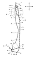
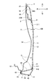
- FIG. 1 is a perspective view showing a state in which a vehicle resin component (side mudguard) according to an embodiment of the present invention is attached to a vehicle (door panel).
- FIG. 2 is a cross-sectional view taken along the line AA showing the first embodiment in the mounting structure of the resin component for a vehicle (side mud guard) shown in FIG.
- FIG. 3 shows a partial perspective view of the panel main body and the reinforcing rib shown in FIG. FIG.
- FIG. 4 shows a detailed perspective view of the locking hole formed in the reinforcing rib shown in FIG.
- FIG. 5 is a schematic cross-sectional view when the vehicle resin component shown in FIG. 2 is taken out from the movable mold.
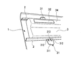
- FIG. 6 is a perspective view for explaining the structure before the upper mounting member shown in FIG. 2 is locked to the reinforcing rib.
- FIG. 7 is a perspective view for explaining the structure after the upper mounting member shown in FIG. 2 is locked to the reinforcing rib.
- FIG. 8 is a detailed cross-sectional view of a portion B shown in FIG.
- the side mud guard 10 is attached to a side surface of a door panel 5 that is attached to a side opening of a vehicle 20 so as to be freely opened and closed, and extends in a vehicle vertical direction and a vehicle front-rear direction. It is a part.
- the side mudguard 10 is required not only for the mudguard function during travel but also for high design as an aero part. For this reason, the side mud guard 10 is required to have the same appearance quality as that of the door panel 5.
- the door panel 5 includes a door inner 52 disposed on the vehicle inner side and a door outer 51 disposed on the vehicle outer side.
- the side mud guard 10 is attached to the outer surface of the door outer 51.
- the side mud guard 10 includes a panel body 1 that covers the door outer 51, reinforcing ribs 2 that are erected on the back surface 12 of the panel body 1, and attachment members 3 and 4 to the door outer 51.
- the panel body 1 is formed with a substantially constant thickness from the upper outer peripheral edge 13 to the lower outer peripheral edge 14, and forms a design surface that emphasizes the appearance of the design.
- the reinforcing rib 2 is erected at a substantially constant height from the back surface 12 of the panel body 1 toward the inside of the vehicle in order to ensure the rigidity of the panel body 1.
- the reinforcing ribs 2 are linearly extended in the vehicle front-rear direction, and a plurality of reinforcing ribs 2 are formed at appropriate intervals in the vertical direction between the upper outer peripheral edge 13 and the lower outer peripheral edge 14 of the panel body 1. Yes.
- the cross section is open at the longitudinal end 24 of the reinforcing rib 2.
- the reinforcing rib 2 is formed so that the thickness of the base end portion 21 connected to the panel body 1 is thinner than the thickness of the tip end portion 22. Further, one side wall of the reinforcing rib 2 has a base end portion 21 and a front end portion 22 formed on the same surface, and the other side wall of the reinforcing rib 2 is thicker from the end of the base end portion 21 toward the front end side. Is formed with a step surface connecting the flat surface of the base end portion 21 and the flat surface of the distal end portion 22 with an inclined surface. The inclined surface 23 constitutes a negative angle portion at the time of injection molding.
- the distal end portion 22 of the reinforcing rib 2 is provided with a locking hole 25 that is bored with the hole direction inclined in substantially the same direction as the inclined direction of the inclined surface 23.
- the inclination direction of the inclined surface 23 and the hole direction of the locking hole 25 are within an allowable range even if they differ by at least about 5 to 10 degrees.
- the internal angle ⁇ 1 formed by the rising direction of the reinforcing rib 2 (the direction of the arrow P) and the inclined direction of the inclined surface 23 is the rising direction of the reinforcing rib 2 (the direction of the arrow P) and the hole direction of the locking hole 25.
- the inner angle ⁇ 1 and the inner angle ⁇ 2 are each formed at about 40 to 50 degrees. Since the locking hole 25 penetrates both side walls of the distal end portion 22, the drilled hole cross section is formed in a substantially parallelogram. The opening of the locking hole 25 is formed in a rectangle having the longitudinal direction of the reinforcing rib 2 as a long side.
- the die cutting direction (the direction of arrow Q) is the same as the direction in which the reinforcing rib 2 is erected.
- the inclined surface 23 of the reinforcing rib 2 rises along the negative angle forming portion 61, and the distal end portion 22 of the reinforcing rib is negative angle forming portion 61.
- the locking hole 25 can be released from the locking hole forming part 62 at the same time as it is tilted away from the locking hole.
- the movable die 6 does not need to have a locking hole slide mold or the like having a complicated mold structure, and the locking hole 25 can be formed with a simple mold structure.
- the attachment members 3 and 4 are fixed on the back surface side of the panel body 1 at a position adjacent to the upper outer peripheral edge 13 and a position adjacent to the lower outer peripheral edge 14.
- the upper mounting member 3 includes a seat portion 34 formed along the side surface shape of the door outer 51, and an upper end portion 36 and a lower end portion 33 that are in contact with the back side of the panel main body 1.
- a plate-like locking claw 31 that protrudes upward is formed on the upper end portion 36, and a plate-like locking claw 31 that protrudes downward is formed on the lower end portion 33. Both the locking claws 31 and 31 have flexibility capable of bending in the plate thickness direction.
- a plate-like knob portion 311 that can penetrate the locking hole 25 is formed on the front end side of both the locking claws 31, 31, and a claw portion 312 that is locked on the locking hole 25 is formed on the proximal end side. Yes.
- the claw portion 312 is separated by a notch groove 314 and a connecting portion 313 that connects the upper end portion 36 or the lower end portion 33 and the plate-like knob portion 311.
- the distal end side of the locking claw 31 is inserted into the locking hole 25, the plate-like knob portion 311 is gripped, the locking claw 31 is pulled out from the locking hole 25, and the claw portion 312 formed on the proximal end side is engaged. It can be locked to the stop hole 25.
- the locking claw 31 is tilted in the locking hole 25 formed in the distal end portion 22 of the reinforcing rib 2 in the substantially same direction (in the direction of arrow R) as the inclined surface 23.
- the plate-like knob portion 311 protrudes from the opposite side of the locking hole 25, so that the plate-like knob portion 311 is gripped and raised horizontally, and the locking claw 31 is pulled out of the locking hole 25 and the base end
- the claw portion 312 formed on the side can be locked in the locking hole 25.
- the plate-like knob portion 311 contacts the back surface 12 of the panel body 1 in a curved state. When the plate-like knob portion 311 is curved, the claw portion 312 is difficult to be detached from the locking hole 25.
- the attachment member 3 is pulled in the direction of the arrow R via the locking claw 31, and the upper end portion 36 and the lower end portion 33 abut against the back surface 12 of the panel main body 1, respectively. Fixed to.
- the lower mounting member 4 includes a seat 43 formed along the lower end flange shape of the door outer 51, an upper end 44 that contacts the back side of the panel main body 1, and the panel main body 1.
- the lower outer periphery 14 and the lower end part 46 connected via the integral hinge 45 are provided.
- a plate-like locking claw 41 that protrudes upward is formed on the upper end portion 44.
- the locking claw 41 has the same structure as the locking claw 31 of the mounting member 3 described above.
- the front end side of the locking claw 41 is inserted into the locking hole 25, the plate-like knob portion 411 is gripped, the locking claw 41 is pulled out from the locking hole 25, and the claw portion 412 formed on the proximal end side is engaged. It can be locked to the stop hole 25.
- the lower mounting member 4 is fixed to the back surface 12 of the panel body 1 via the locking claw 41 and the integral hinge 45.
- the attachment members 3 and 4 and the door outer 51 are fixed using the adhesive sheets 32 and 42.
- the adhesive sheets 32 and 42 are double-sided adhesive sheets formed in a rectangular shape.
- ⁇ Specific mounting method is as follows. That is, the adhesive sheets 32 and 42 are attached in advance to the seat portions 34 and 43 of the attachment members 3 and 4.
- the attachment members 3 and 4 to which the adhesive sheets 32 and 42 are attached are fixed to the back surface 12 of the panel body 1 by the locking claws 31 and 41.
- a predetermined portion of the door outer 51 to which the adhesive sheets 32 and 42 are attached is preferably primed with thinner or the like.
- the side mud guard 10 to which the attachment members 3 and 4 are fixed is positioned in contact with the door outer 51 and is held for a predetermined time to adhere the adhesive sheets 32 and 42.
- the side mudguard 10 is fixed to the door panel 5 via the adhesive sheets 32 and 42.
- FIG. 9 is a cross-sectional view taken along line AA showing a second embodiment of the mounting structure of the resin component for vehicle (side mud guard) shown in FIG.
- FIG. 10 is a perspective view showing a state in which the upper mounting member shown in FIG. 9 is inverted via the integral hinge.
- FIG. 11 is a perspective view for explaining the structure before and after the upper mounting member shown in FIG. 9 is locked to the reinforcing rib.
- the side mud guard 10B according to the present embodiment is common to the first embodiment except for the upper mounting member 3B. Therefore, it demonstrates centering on the upper attachment member 3B which is different, attaches
- the upper mounting member 3 ⁇ / b> B is capable of rotating a seat portion 34 ⁇ / b> B formed along the side surface shape of the door outer 51, the upper end of the seat portion 34 ⁇ / b> B, and the upper outer periphery 13 of the panel body 1.
- An integral hinge 35 to be connected and a lower end portion 33B extending from the lower end of the seat portion 34B and abutting against the back side of the panel body 1 are provided.
- a plate-like locking claw 31 protruding downward is formed at the lower end 33B.
- the locking claw 31 has the same structure as the locking claw 31 of the first embodiment described above.
- the front end side of the locking claw 31 can be inserted into the locking hole 25 of the adjacent reinforcing rib 2 and locked to the locking hole 25.
- the upper mounting member 3 ⁇ / b> B is fixed to the back surface 12 of the panel body 1 via the locking claw 31 and the integral hinge 35.
- the upper mounting member 3 ⁇ / b> B is inverted via the integral hinge 35 and extends upward from the upper outer peripheral edge 13 of the panel body 1. Mold together. Since the panel main body 1 and the attachment member 3B can be integrally molded, the material yield is improved and the mold cost can be reduced. Further, since the locking claws 31 can be fitted into the locking holes 25 of the adjacent reinforcing ribs 2 simply by reversing the mounting member 3B after molding, the panel body 1 and the mounting member 3B can be quickly mounted. This improves the mounting position accuracy.
- the reinforcing rib 2 has the distal end portion 21 connected to the panel body 1 having a thick wall at the tip. Since it is thinner than the thickness of the part 22, it is difficult to cause sink marks or the like on the surface 11 (design surface) of the panel body 1, and there is no possibility of causing a problem in appearance quality.
- the distal end portion 22 is formed with an inclined surface 23 that increases in thickness toward the distal end side between the proximal end portion 21, and the latch is provided with the hole direction inclined to the inclined direction of the inclined surface. Since the hole 25 is provided, the negative angle forming portion 61 for forming the inclined surface 23 of the tip end portion 22 and the locking hole forming portion 62 for forming the locking hole 25 are integrally connected in the movable die 6 of the molding die. be able to. Therefore, when the side mud guards 10 and 10B are taken upward from the movable mold 6 of the molding die, the inclined surface 23 of the tip 22 rises along the negative angle molding 61 and the tip 22 of the reinforcing rib 2 is negative.
- the locking hole 25 can be released from the locking hole forming portion 62. Therefore, it is not necessary to provide the movable mold 6 with a locking hole slide mold having a complicated mold structure, and the locking hole 25 can be formed with a simple mold structure. Therefore, an increase in mold costs can be suppressed.
- the attachment members 3, 3 ⁇ / b> B, 4 are formed with engagement claws 31, 41 that can be fitted into the engagement holes 25, and the attachment members 3, 3 ⁇ / b> B, 4 are engaged by engaging the engagement claws with the engagement holes.
- the mounting member is adhesively fixed to the door panel 5, so that the side mud guards 10, 10 B can be mounted on the vehicle without integrally forming the mounting members 3, 3 B, 4 on the back surface 12 of the panel body 1. It can be fixed to 20 door panels 5. Therefore, there is no fear that sink marks or the like associated with the molding of the mounting members 3, 3 ⁇ / b> B, and 4 occur on the surface 11 (design surface) of the panel body 1, and the appearance quality problem can be solved.
- a vehicle resin component mounting structure that can be formed with a simple mold structure without causing defects such as sink marks on the surface (design surface) of the side mudguard 10, 10B, which is a resin component for vehicles, is provided. can do.
- the attachment members 3B, 4 are such that the ends facing the locking claws 31, 41 have the upper outer peripheral edge 13 or the lower outer peripheral edge 14 of the panel body 1 via the integral hinges 35, 45. Therefore, the mounting members 3B and 4 inverted through the integral hinges 35 and 45 can be integrated with the panel body 1 and formed with a simple mold structure. Further, since the attachment members 3B and 4 are connected to the upper outer peripheral edge 13 or the lower outer peripheral edge 14 of the panel main body 1 via the integral hinges 35 and 45, the surface 11 (design surface) of the panel main body 1 sinks. Etc. are unlikely to occur.
- the tabs 311 and 411 that can penetrate the locking holes 25 are formed in the locking claws 31 and 41 on the front end side, and the claw portions 312 that are locked to the locking holes 25 are formed.
- 412 is formed on the proximal end side, so that the distal ends of the locking claws 31 and 41 are inserted into the locking holes 25, the plate-like knob portions 311 and 411 are gripped, and the locking claws are pulled out from the locking holes.
- the claw portions 312 and 412 formed on the proximal end side can be locked in the locking hole 25.
- the plate-like knob portions 311, 411 are moved from the opposite side of the locking holes 25. Since it protrudes, the plate-like knob portions 311 and 411 are gripped and raised horizontally, and the locking claws 31 and 41 are pulled out from the locking holes 25 to form the claw portions 312 and 412 formed on the proximal end side. Can be easily and reliably locked.
- the attachment member 4 on the lower outer peripheral side of the panel body 1 is fixed to the panel body 1 by the integral hinge 45 and the locking claw 41, but the present invention is not limited to this.
- the integral hinge 45 can be changed to the locking claw 41.
- the present invention can be used, for example, as an attachment structure for exterior resin parts (such as side mudguards) attached to the outer surface of an automobile.
- exterior resin parts such as side mudguards
Landscapes
- Engineering & Computer Science (AREA)
- Mechanical Engineering (AREA)
- General Engineering & Computer Science (AREA)
- Chemical & Material Sciences (AREA)
- Combustion & Propulsion (AREA)
- Transportation (AREA)
- Body Structure For Vehicles (AREA)
- Connection Of Plates (AREA)
- Vehicle Interior And Exterior Ornaments, Soundproofing, And Insulation (AREA)
Abstract
Description
まず、本発明に係る第1実施形態である車両用樹脂部品の取付け構造について、ドアパネルに取り付けたサイドマッドガードの例で、図1~図9を用いて詳細に説明する。図1に、本発明に係る実施形態である車両用樹脂部品(サイドマッドガード)を車両(ドアパネル)へ取付けた状態を表す斜視図を示す。図2に、図1に示す車両用樹脂部品(サイドマッドガード)の取付け構造における第1実施形態を表すA-A断面図を示す。図3に、図2に示すパネル本体及び補強リブの部分斜視図を示す。図4に、図2に示す補強リブに形成した係止孔の詳細斜視図を示す。図5に、図2に示す車両用樹脂部品を可動型から取り出すときの模式的断面図を示す。図6に、図2に示す上部取付け部材を補強リブに係止する前の構造を説明する斜視図を示す。図7に、図2に示す上部取付け部材を補強リブに係止した後の構造を説明する斜視図を示す。図8に、図2に示すB部詳細断面図を示す。
次に、本発明に係る第2実施形態である車両用樹脂部品の取付け構造について、ドアパネル5に取り付けたサイドマッドガード10Bの例で、図9~図11を用いて詳細に説明する。図9に、図1に示す車両用樹脂部品(サイドマッドガード)の取付け構造における第2実施形態を表すA-A断面図を示す。図10に、図9に示す上部取付け部材をインテグラルヒンジを介して反転した状態を表す斜視図を示す。図11に、図9に示す上部取付け部材を補強リブに係止する前後の構造を説明する斜視図を示す。
以上、詳細に説明したように、本実施形態に係る車両用樹脂部品(サイドマッドガード)の取付け構造によれば、補強リブ2は、パネル本体1と連結された基端部21の肉厚が先端部22の肉厚より薄いので、パネル本体1の表面11(意匠面)にヒケ等を生じさせにくく、外観面品質上の問題を発生させる恐れはない。
2 補強リブ
3、3B、4 取付け部材
5 ドアパネル
6 可動型
10、10B サイドマッドガード(車両用樹脂部品)
11 パネル本体の表面
12 パネル本体の裏面
13 上外周縁
14 下外周縁
20 車両
21 基端部
22 先端部
23 傾斜面
25 係止孔
31、41 係止爪
32、42 接着シート
35、45 インテグラルヒンジ
311、411 板状つまみ部
312、412 爪部
Claims (3)
- 表面に意匠面を有するパネル本体と、該パネル本体の裏面に立設した補強リブと、車両への取付け部材とを備えた車両用樹脂部品の取付け構造であって、
前記補強リブは、前記パネル本体と連結された基端部の肉厚が先端部の肉厚より薄く形成されたこと、
前記先端部には、前記基端部との間に先端側に向けて肉厚が増加する傾斜面が形成され、当該傾斜面の傾斜方向に孔方向が傾斜して穿設された係止孔を備えたこと、
前記取付け部材には、前記係止孔に嵌合可能な係止爪が形成され、前記係止孔に前記係止爪を係止して前記取付け部材を前記パネル本体の裏面に固定し、前記取付け部材を前記車両に固定したことを特徴とする車両用樹脂部品の取付け構造。 - 請求項1に記載された車両用樹脂部品の取付け構造において、
前記取付け部材は、前記係止爪と対向する端部がインテグラルヒンジを介して前記パネル本体の外周縁に連結されていることを特徴とする車両用樹脂部品の取付け構造。 - 請求項1又は請求項2に記載された車両用樹脂部品の取付け構造において、
前記係止爪には、前記係止孔を貫通できる板状つまみ部が前端側に形成され、前記係止孔に係止する爪部が基端側に形成されたことを特徴とする車両用樹脂部品の取付け構造。
Priority Applications (2)
| Application Number | Priority Date | Filing Date | Title |
|---|---|---|---|
| US14/888,612 US10081394B2 (en) | 2013-12-17 | 2014-09-26 | Mounting structure of vehicular resin component |
| CN201480029761.8A CN105246741B (zh) | 2013-12-17 | 2014-09-26 | 车辆用树脂零件的安装构造 |
Applications Claiming Priority (2)
| Application Number | Priority Date | Filing Date | Title |
|---|---|---|---|
| JP2013260656A JP6156120B2 (ja) | 2013-12-17 | 2013-12-17 | 車両用樹脂部品の取付け構造 |
| JP2013-260656 | 2013-12-17 |
Publications (1)
| Publication Number | Publication Date |
|---|---|
| WO2015093121A1 true WO2015093121A1 (ja) | 2015-06-25 |
Family
ID=53402478
Family Applications (1)
| Application Number | Title | Priority Date | Filing Date |
|---|---|---|---|
| PCT/JP2014/075568 Ceased WO2015093121A1 (ja) | 2013-12-17 | 2014-09-26 | 車両用樹脂部品の取付け構造 |
Country Status (5)
| Country | Link |
|---|---|
| US (1) | US10081394B2 (ja) |
| JP (1) | JP6156120B2 (ja) |
| CN (1) | CN105246741B (ja) |
| MY (1) | MY173500A (ja) |
| WO (1) | WO2015093121A1 (ja) |
Families Citing this family (6)
| Publication number | Priority date | Publication date | Assignee | Title |
|---|---|---|---|---|
| CN205523589U (zh) * | 2016-03-31 | 2016-08-31 | 四维尔丸井(广州)汽车零部件有限公司 | 一种轿车车门安全防护结构 |
| CN105835669B (zh) * | 2016-03-31 | 2019-01-18 | 四维尔丸井(广州)汽车零部件有限公司 | 一种轿车车门侧裙安装结构 |
| AU201712992S (en) * | 2017-05-17 | 2017-05-29 | Aluminium Industries Invest Pty Ltd | An extrusion |
| JP7599328B2 (ja) * | 2020-12-25 | 2024-12-13 | 株式会社ファルテック | サイドモール |
| JP7611879B2 (ja) * | 2022-09-01 | 2025-01-10 | 森六テクノロジー株式会社 | 樹脂成形品 |
| TR2024003782A2 (tr) * | 2024-03-27 | 2024-07-22 | Tirsan Treyler Sanayi̇ Ve Ti̇caret Anoni̇m Şi̇rketi̇ | Bir Bağlantı Braketi |
Citations (7)
| Publication number | Priority date | Publication date | Assignee | Title |
|---|---|---|---|---|
| JPS61176013U (ja) * | 1985-04-23 | 1986-11-01 | ||
| JPH10244968A (ja) * | 1997-03-03 | 1998-09-14 | Toyota Auto Body Co Ltd | 車両のサイドマッドガード |
| JP2000016342A (ja) * | 1998-07-03 | 2000-01-18 | Toyota Auto Body Co Ltd | 車両のサイドマッドガードの端末取付け構造 |
| JP2004276796A (ja) * | 2003-03-17 | 2004-10-07 | Toyoda Gosei Co Ltd | 車両用外装部品及び発信部の取付構造 |
| JP2011020490A (ja) * | 2009-07-14 | 2011-02-03 | Inoac Corp | ピラーガーニッシュ |
| JP2013240999A (ja) * | 2012-04-23 | 2013-12-05 | Toyota Auto Body Co Ltd | 射出成形装置及び補強リブ押出し装置 |
| WO2014112312A1 (ja) * | 2013-01-15 | 2014-07-24 | トヨタ車体株式会社 | 車両用樹脂部品の製造方法及び車両用樹脂部品 |
Family Cites Families (4)
| Publication number | Priority date | Publication date | Assignee | Title |
|---|---|---|---|---|
| JP2007186093A (ja) | 2006-01-13 | 2007-07-26 | Toyota Auto Body Co Ltd | 後付外装部品取付方法 |
| JP4798617B2 (ja) * | 2006-05-19 | 2011-10-19 | 株式会社イノアックコーポレーション | 射出成形品 |
| JP4871830B2 (ja) * | 2007-10-05 | 2012-02-08 | 矢崎総業株式会社 | 2つの部材を連結する係合構造 |
| CN103318104B (zh) | 2013-05-29 | 2016-02-03 | 宁波泰甬汽车零部件有限公司 | 车顶饰条及其安装结构 |
-
2013
- 2013-12-17 JP JP2013260656A patent/JP6156120B2/ja active Active
-
2014
- 2014-09-26 US US14/888,612 patent/US10081394B2/en not_active Expired - Fee Related
- 2014-09-26 MY MYPI2015703634A patent/MY173500A/en unknown
- 2014-09-26 CN CN201480029761.8A patent/CN105246741B/zh not_active Expired - Fee Related
- 2014-09-26 WO PCT/JP2014/075568 patent/WO2015093121A1/ja not_active Ceased
Patent Citations (7)
| Publication number | Priority date | Publication date | Assignee | Title |
|---|---|---|---|---|
| JPS61176013U (ja) * | 1985-04-23 | 1986-11-01 | ||
| JPH10244968A (ja) * | 1997-03-03 | 1998-09-14 | Toyota Auto Body Co Ltd | 車両のサイドマッドガード |
| JP2000016342A (ja) * | 1998-07-03 | 2000-01-18 | Toyota Auto Body Co Ltd | 車両のサイドマッドガードの端末取付け構造 |
| JP2004276796A (ja) * | 2003-03-17 | 2004-10-07 | Toyoda Gosei Co Ltd | 車両用外装部品及び発信部の取付構造 |
| JP2011020490A (ja) * | 2009-07-14 | 2011-02-03 | Inoac Corp | ピラーガーニッシュ |
| JP2013240999A (ja) * | 2012-04-23 | 2013-12-05 | Toyota Auto Body Co Ltd | 射出成形装置及び補強リブ押出し装置 |
| WO2014112312A1 (ja) * | 2013-01-15 | 2014-07-24 | トヨタ車体株式会社 | 車両用樹脂部品の製造方法及び車両用樹脂部品 |
Also Published As
| Publication number | Publication date |
|---|---|
| MY173500A (en) | 2020-01-29 |
| JP6156120B2 (ja) | 2017-07-05 |
| US20160288842A1 (en) | 2016-10-06 |
| US10081394B2 (en) | 2018-09-25 |
| JP2015116897A (ja) | 2015-06-25 |
| CN105246741B (zh) | 2017-05-10 |
| CN105246741A (zh) | 2016-01-13 |
Similar Documents
| Publication | Publication Date | Title |
|---|---|---|
| JP6156120B2 (ja) | 車両用樹脂部品の取付け構造 | |
| CN105083156A (zh) | 用于车门的形成收纳部的装饰板及方法 | |
| CN107444080B (zh) | 车身构造 | |
| JP6202743B2 (ja) | カウルトップカバー | |
| JP2015217926A (ja) | カウルカバー装置 | |
| JP2012011881A (ja) | 車両用内装部材 | |
| US11351845B2 (en) | Door structure | |
| CN105835791B (zh) | 车门用装饰件安装构造 | |
| JP6125476B2 (ja) | 車両用モールディング及び車両におけるモールディングの取付構造 | |
| KR20150058913A (ko) | 차량용 훼스너 | |
| JP6185775B2 (ja) | カウルトップカバー | |
| JP6048786B2 (ja) | 車両のドア構造 | |
| JP4770352B2 (ja) | 車体側部構造 | |
| JP4781900B2 (ja) | カウルトップカバー | |
| JP7201471B2 (ja) | 車両用サイドドア及びその組付方法 | |
| JP2009023536A (ja) | キッキングプレートの合わせ構造 | |
| JP6052210B2 (ja) | 自動車のオーバフェンダ構造 | |
| JP4935493B2 (ja) | 樹脂成形品 | |
| JP5621578B2 (ja) | ウエスト部補強構造 | |
| JP4701922B2 (ja) | ホイールハウスのライニング構造 | |
| CN103313866A (zh) | 用于使机动车辆侧车门的车窗相对于该车门的外部打开控制装置定位的装置 | |
| JP6679460B2 (ja) | クリップの取付構造 | |
| CN102452369B (zh) | 车辆用保险杠外观件 | |
| KR20090008743A (ko) | 차량용 외장 몰딩 | |
| JP5830300B2 (ja) | 樹脂射出成形品 |
Legal Events
| Date | Code | Title | Description |
|---|---|---|---|
| 121 | Ep: the epo has been informed by wipo that ep was designated in this application |
Ref document number: 14872518 Country of ref document: EP Kind code of ref document: A1 |
|
| WWE | Wipo information: entry into national phase |
Ref document number: 14888612 Country of ref document: US |
|
| WWE | Wipo information: entry into national phase |
Ref document number: IDP00201507274 Country of ref document: ID |
|
| NENP | Non-entry into the national phase |
Ref country code: DE |
|
| 122 | Ep: pct application non-entry in european phase |
Ref document number: 14872518 Country of ref document: EP Kind code of ref document: A1 |