WO2015092924A1 - 軸流送風機 - Google Patents
軸流送風機 Download PDFInfo
- Publication number
- WO2015092924A1 WO2015092924A1 PCT/JP2013/084322 JP2013084322W WO2015092924A1 WO 2015092924 A1 WO2015092924 A1 WO 2015092924A1 JP 2013084322 W JP2013084322 W JP 2013084322W WO 2015092924 A1 WO2015092924 A1 WO 2015092924A1
- Authority
- WO
- WIPO (PCT)
- Prior art keywords
- protruding portion
- edge side
- propeller fan
- radial
- flow
- Prior art date
Links
Images


Classifications
-
- F—MECHANICAL ENGINEERING; LIGHTING; HEATING; WEAPONS; BLASTING
- F04—POSITIVE - DISPLACEMENT MACHINES FOR LIQUIDS; PUMPS FOR LIQUIDS OR ELASTIC FLUIDS
- F04D—NON-POSITIVE-DISPLACEMENT PUMPS
- F04D29/00—Details, component parts, or accessories
- F04D29/26—Rotors specially for elastic fluids
- F04D29/32—Rotors specially for elastic fluids for axial flow pumps
- F04D29/38—Blades
- F04D29/384—Blades characterised by form
-
- F—MECHANICAL ENGINEERING; LIGHTING; HEATING; WEAPONS; BLASTING
- F04—POSITIVE - DISPLACEMENT MACHINES FOR LIQUIDS; PUMPS FOR LIQUIDS OR ELASTIC FLUIDS
- F04D—NON-POSITIVE-DISPLACEMENT PUMPS
- F04D19/00—Axial-flow pumps
- F04D19/002—Axial flow fans
-
- F—MECHANICAL ENGINEERING; LIGHTING; HEATING; WEAPONS; BLASTING
- F04—POSITIVE - DISPLACEMENT MACHINES FOR LIQUIDS; PUMPS FOR LIQUIDS OR ELASTIC FLUIDS
- F04D—NON-POSITIVE-DISPLACEMENT PUMPS
- F04D29/00—Details, component parts, or accessories
- F04D29/66—Combating cavitation, whirls, noise, vibration or the like; Balancing
- F04D29/661—Combating cavitation, whirls, noise, vibration or the like; Balancing especially adapted for elastic fluid pumps
- F04D29/667—Combating cavitation, whirls, noise, vibration or the like; Balancing especially adapted for elastic fluid pumps by influencing the flow pattern, e.g. suppression of turbulence
-
- F—MECHANICAL ENGINEERING; LIGHTING; HEATING; WEAPONS; BLASTING
- F05—INDEXING SCHEMES RELATING TO ENGINES OR PUMPS IN VARIOUS SUBCLASSES OF CLASSES F01-F04
- F05D—INDEXING SCHEME FOR ASPECTS RELATING TO NON-POSITIVE-DISPLACEMENT MACHINES OR ENGINES, GAS-TURBINES OR JET-PROPULSION PLANTS
- F05D2240/00—Components
- F05D2240/20—Rotors
- F05D2240/30—Characteristics of rotor blades, i.e. of any element transforming dynamic fluid energy to or from rotational energy and being attached to a rotor
- F05D2240/304—Characteristics of rotor blades, i.e. of any element transforming dynamic fluid energy to or from rotational energy and being attached to a rotor related to the trailing edge of a rotor blade
Definitions
- the present invention relates to an axial fan.
- an axial blower that reduces noise by improving the blade structure is an axial blower disclosed in Patent Document 1.
- the radial center of the trailing edge of the blade is formed in a protruding shape that is curved so as to swell toward the suction side, and the gas discharge speed is made uniform in the radial direction of the blade.
- Patent No. 45015575 (mainly FIGS. 3 and 8)
- the present invention has been made in view of the above, and an object thereof is to provide an axial blower capable of suppressing an increase in noise.
- the present invention includes a propeller fan and a drive unit that rotates the propeller fan, and the propeller fan includes the hub and a plurality of blades supported by the hub.
- the propeller fan includes the hub and a plurality of blades supported by the hub.
- Each of the pressure surfaces of the blades has a protruding portion curved so as to swell toward the suction side, and the height of the protruding portion on the trailing edge side of the blade is The radial position of the apex of the protruding part on the rear edge side is higher in the radial direction than the radial position of the apex of the protruding part on the front edge side.
- blade may be curving so that it may warp to the suction side.
- the position of the inner end of the protruding portion on the rear edge side may be configured to be radially inward from the position of the inner end of the protruding portion on the front edge side.
- Embodiment 1 It is sectional drawing of the axial blower which concerns on Embodiment 1 of this invention. It is a perspective view of the propeller fan of the axial-flow fan in Embodiment 1. It is a top view which picks up and shows one wing
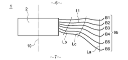
- FIG. FIG. 5 is a view similar to FIG. 4, particularly showing only the pressure surface on one radial section.
- FIG. 1 is a cross-sectional view of an axial blower according to Embodiment 1 of the present invention
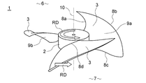
- FIG. 2 is a perspective view of a propeller fan of the axial blower according to Embodiment 1.
- the axial blower 100 includes a propeller fan 1, a motor 4 that is a drive unit, and a bell mouth 5.
- the propeller fan 1 has a hub 2 and a plurality of blades 3.
- the plurality of blades 3 are supported by the hub 2, and are arranged radially on the outer peripheral surface of the substantially cylindrical (including frustoconical) hub 2.
- the example of illustration has shown the propeller fan provided with three blades.
- the central portion of the hub 2 is connected to the motor 4, and the propeller fan 1 is rotated by receiving the driving force of the motor 4.
- a bell mouth 5 is disposed outside the propeller fan 1 in the radial direction. That is, the propeller fan 1 is surrounded by the bell mouth 5 in a state where an appropriate gap is formed between the outer periphery of the propeller fan 1 and the inner periphery of the bell mouth 5.
- 1 is the suction side 6 and the space below the paper surface in FIG. 1 is the discharge side 7.
- Each of the blades 3 is a forward blade whose front edge extends forward in the rotation direction RD.
- the edge facing forward in the rotational direction RD is referred to as a front edge 8a
- the edge facing backward in the rotational direction RD is referred to as a rear edge 8c.
- a portion connecting the radially outer portion of the trailing edge 8c is referred to as an outer peripheral edge 8b.
- a portion where the blade 3 and the hub 2 are connected is referred to as a connection edge 8d.
- one surface of the blade 3 surrounded by the front edge 8a, the outer peripheral edge 8b, the rear edge 8c, and the connection edge 8d is a negative pressure surface 9a, and the other surface is a pressure surface 9b.
- the negative pressure surface 9 a is a surface on the suction side 6, and the pressure surface 9 b is a surface on the discharge side 7.
- the rotation center line of the propeller fan 1 is referred to as a rotation shaft 10.
- the white arrow in the figure indicates the rotation direction RD of the propeller fan, and the broken arrow schematically indicates the gas flow.
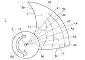
- FIG. 3 is a plan view showing one wing.
- FIG. 4 is a diagram showing a change in the circumferential direction of the pressure surface on the radial surface including the rotation axis in relation to the first embodiment. It is. Further, FIG. 5 is a view of the same mode as FIG. 4, and particularly shows only the pressure surface on one radial cross section. Dotted lines A1 to A6 in FIG. 3 indicate radial cross-sectional lines between the hub and the blade. These alternate long and short dash lines A1 to A6 include the rotation shaft and continuously extend from the connection edge to the outer peripheral edge. Also, the lines B1 to B6 in FIG. 4 indicate the pressure surfaces in the cross sections of the alternate long and short dash lines A1 to A6, respectively. Further, FIG. 5 illustrates only the pressure surface indicated by line B3 in FIG.
- the shape of the pressure surface of the blade 3 will be described with reference to one pressure surface in FIG.
- the pressure surface 9 b has a protruding portion 11 that is curved so as to swell toward the suction side 6.
- a portion that bulges from the straight line BL to the suction side 6 by applying the straight line BL (two-dot chain line in the figure) from the discharge side 7 to the pressure surface 9 b is the protruding portion 11.
- the end on the outer peripheral edge side of the wing 3 and the end on the connection edge side in the protruding portion 11 are referred to as an outer end 11a and an inner end 11b of the protruding portion, respectively.
- a point at which the protruding portion 11 is farthest from the straight line BL (two-dot chain line) is defined as a vertex 11c of the protruding portion.
- the distance between the apex 11 c of the protruding portion 11 and the straight line BL (two-dot chain line) is defined as the height H of the protruding portion 11.
- the blade 3 according to the first embodiment has an angular range in which a radial cross section continuously exists from the connection edge 8d to the outer peripheral edge 8b among the radial cross sections (the angular range of the one-dot chain lines A1 to A6 in FIG. 3). ),
- the pressure surface 9 b has a protruding portion 11 that curves so as to swell toward the suction side 6.
- the outer end 11 a of the protruding portion 11 is located on the radially inner side with respect to the outer peripheral edge 8 b of the wing 3.
- the height H of the protruding portion 11 on the rear edge side is higher than the height H of the protruding portion 11 on the front edge side.
- the height H of the protruding portion 11 becomes higher in a portion closer to the rear edge within the angle range of the alternate long and short dash lines A1 to A6.
- the radial position (radial position) of the apex 11c of the protruding portion 11 on the rear edge side is radially inward from the radial position (radial position) of the apex 11c of the protruding portion 11 on the front edge side.
- the position in the radial direction of the protruding portion 11 is more radially inward as the portion closer to the trailing edge is within the angular range of the alternate long and short dash lines A1 to A6.
- the position of the inner end 11b of the protruding portion 11 on the rear edge side is radially inward from the position of the inner end 11b of the protruding portion 11 on the front edge side.
- the position of the inner end 11b of the protruding portion 11 is more radially inward as the portion closer to the rear edge within the angle range of the alternate long and short dash lines A1 to A6.
- the curve Lb connecting the inner ends 11b of the projecting portion 11 is located radially inward as it goes to the rear edge within the angle range of the alternate long and short dash lines A1 to A6.
- the width dimension W of the protruding portion 11 on the rear edge side is wider than the width dimension W of the protruding portion 11 on the front edge side.
- the width dimension W of the protruding portion 11 is wider in the angular range of the alternate long and short dash lines A1 to A6 as the portion is closer to the rear edge.
- the outer peripheral edge 8 b of the wing 3 is curved so as to warp the suction side 6.
- the radial distribution of the axial flow velocity in the vicinity of the trailing edge on the discharge side of a general axial fan increases in the radial direction from the radially inner side to the radially outer side, and is slightly outside the radial center. And then decreases toward the outer periphery, which is the position of the maximum radius.
- the flow is reduced in the radial direction due to centrifugal force, so that the flow rate on the hub side decreases. For this reason, the blade surface separation flow occurs due to the insufficient flow rate, and noise increases due to the turbulence due to such separation, or the efficiency decreases due to separation.
- the flow rate increases on the outer peripheral side of the blade in the radial direction, because the flow rate is concentrated. Since the aerodynamic noise of the propeller fan mainly increases in proportion to the sixth power of the flow velocity, there is a problem that the noise increases as the flow velocity increases. In this way, on the discharge side, a flow velocity distribution occurs in the radial direction of the blades, resulting in a slow flow on the hub side and a fast flow on the outer peripheral side, resulting in noise increase problems and efficiency reduction problems due to flow velocity distribution. Occurs.
- the protruding portion 11 on the pressure surface 9b of the blade 3, it is possible to suppress the appearance of a flow distribution that causes the above-described problem in the radial direction.
- the pressure surface 9b acts to push gas in the direction of the discharge side 7.
- the protruding portion 11 serves as an escape path for the gas to be pushed, and a flow toward the protruding portion 11 occurs on the pressure surface 9b.
- the radial position of the apex 11c of the protrusion 11 on the rear edge side is radially inward from the radial position of the apex 11c of the protrusion 11 on the front edge.
- action which moves the gas which exists in the radial direction outer side on the pressure surface 9b to a radial direction inner side is acquired, and the movement of the gas to the radial direction outer side by centrifugal force can be reduced.
- the height H of the protruding portion 11 on the rear edge side is higher than the height H of the protruding portion 11 on the front edge side. For this reason, the effect
- the entire angle range in which a radial cross section exists continuously from the connection edge 8d to the outer peripheral edge 8b the pressure surface continues in the radial direction from the connection edge 8d to the outer peripheral edge 8b. Since the projecting portion 11 is formed over the entire existing angle range), the radial flow distribution can be controlled without causing a sudden change in the gas flow, and the turbulence of the gas can be controlled. It is possible to suppress noise increase and efficiency decrease due to gas turbulence.
- the flow from the pressure surface to the suction surface occurs outside the outer periphery due to the pressure difference between the pressure surface and the suction surface in the vicinity of the outer periphery.
- the radially outer side of the protruding portion is inclined so as to push the gas toward the inner peripheral side, and the pressure is increased to increase the entrainment flow from the pressure surface to the suction surface. Since the outer end of the protruding portion is arranged on the inner peripheral side with respect to the outer peripheral edge, it is suppressed that the entrainment flow generated outside the outer peripheral edge is strengthened.
- the outer peripheral edge of the wing is curved so as to warp toward the suction side, that is, the outer peripheral edge 8b is closer to the suction side 6 than the straight line BL (two-dot chain line) in FIG. To position.
- the outer peripheral edge is curved and warps to the suction side, so that it flows from the pressure surface to the outside of the outer peripheral edge.
- the pressure change starts, and the sudden pressure change thereafter can be suppressed to reduce the disturbance of the entrainment.
- the position of the entanglement flow can be separated from the suction surface to the suction side, so that it is difficult to be affected by the entrainment flow.
- the position of the inner end 11b of the protruding portion 11 on the rear edge side is radially inward from the position of the inner end 11b of the protruding portion 11 on the front edge side. For this reason, the effect
- the width dimension W of the protruding portion 11 on the rear edge side is wider than the width dimension W of the protruding portion 11 on the front edge side. For this reason, when the radial shape distribution of the flow velocity on the discharge side is made closer to the uniform by providing the protruding portion, the width capable of controlling the radial distribution of the flow velocity on the discharge side can be expanded.
- the flow velocity distribution in the axial direction on the discharge side can be made to be uniform, the increase in noise and the decrease in efficiency caused by the large flow velocity distribution are suppressed.
- a low noise, high efficiency propeller fan can be obtained.
- it is possible to suppress the turbulence of the flow, which may occur due to the uniform flow velocity it is possible to enhance the effect of low noise and high efficiency.
- An example of utilization of the present invention is an air conditioner outdoor unit.
- the axial blower of the present invention as a blower for an outdoor unit of an air conditioner, it is possible to reduce aerodynamic noise when a required air volume is generated, and to reduce necessary power. That is, an air conditioner with low noise and excellent energy saving performance can be obtained.
Abstract
Description
また、前記翼のそれぞれの外周縁は、吸込み側に反っているように湾曲しているように構成してもよい。
また、前記後縁側の突形状部の内側端の位置は、前記前縁側の突形状部の内側端の位置よりも、径方向内側にあるように構成してもよい。
さらに、前記後縁側の突形状部の幅寸法は、前記前縁側の突形状部の幅寸法よりも、広くなるように構成してもよい。
図1は、本発明の実施の形態1に係る軸流送風機の断面図であり、図2は、本実施の形態1における軸流送風機のプロペラファンの斜視図である。軸流送風機100は、プロペラファン1と、駆動部であるモータ4と、ベルマウス5とを備えている。
Claims (4)
- プロペラファンと、該プロペラファンを回転させる駆動部とを備え、
前記プロペラファンは、前記ハブと、該ハブに支持された複数の翼とを有している、軸流送風機であって、
前記翼のそれぞれの圧力面は、吸込み側に膨らむように湾曲した突形状部を有しており、
該翼の後縁側の前記突形状部の高さは、前縁側の前記突形状部の高さよりも高く、
前記後縁側の突形状部の頂点の径方向位置は、前記前縁側の突形状部の頂点の径方向位置よりも、径方向内側にある、
軸流送風機。 - 前記翼のそれぞれの外周縁は、吸込み側に反っているように湾曲している、
請求項1の軸流送風機。 - 前記後縁側の突形状部の内側端の位置は、前記前縁側の突形状部の内側端の位置よりも、径方向内側にある、
請求項1又は2の軸流送風機。 - 前記後縁側の突形状部の幅寸法は、前記前縁側の突形状部の幅寸法よりも、広い、
請求項1~3の何れか一項の軸流送風機。
Priority Applications (3)
| Application Number | Priority Date | Filing Date | Title |
|---|---|---|---|
| EP13899760.6A EP3085966B1 (en) | 2013-12-20 | 2013-12-20 | Axial flow fan |
| JP2015553308A JPWO2015092924A1 (ja) | 2013-12-20 | 2013-12-20 | 軸流送風機 |
| PCT/JP2013/084322 WO2015092924A1 (ja) | 2013-12-20 | 2013-12-20 | 軸流送風機 |
Applications Claiming Priority (1)
| Application Number | Priority Date | Filing Date | Title |
|---|---|---|---|
| PCT/JP2013/084322 WO2015092924A1 (ja) | 2013-12-20 | 2013-12-20 | 軸流送風機 |
Publications (1)
| Publication Number | Publication Date |
|---|---|
| WO2015092924A1 true WO2015092924A1 (ja) | 2015-06-25 |
Family
ID=53402316
Family Applications (1)
| Application Number | Title | Priority Date | Filing Date |
|---|---|---|---|
| PCT/JP2013/084322 WO2015092924A1 (ja) | 2013-12-20 | 2013-12-20 | 軸流送風機 |
Country Status (3)
| Country | Link |
|---|---|
| EP (1) | EP3085966B1 (ja) |
| JP (1) | JPWO2015092924A1 (ja) |
| WO (1) | WO2015092924A1 (ja) |
Cited By (10)
| Publication number | Priority date | Publication date | Assignee | Title |
|---|---|---|---|---|
| WO2018158859A1 (ja) * | 2017-02-28 | 2018-09-07 | 三菱電機株式会社 | プロペラファン、送風機及び空気調和機 |
| CN108506247A (zh) * | 2018-05-09 | 2018-09-07 | 约克广州空调冷冻设备有限公司 | 叶片及使用其的轴流叶轮 |
| WO2018190267A1 (ja) * | 2017-04-14 | 2018-10-18 | ダイキン工業株式会社 | プロペラファン |
| WO2019069374A1 (ja) * | 2017-10-03 | 2019-04-11 | 三菱電機株式会社 | プロペラファンおよび軸流送風機 |
| US10539149B2 (en) * | 2015-12-11 | 2020-01-21 | Delta Electronics, Inc. | Impeller and fan |
| JP2021017819A (ja) * | 2019-07-18 | 2021-02-15 | 株式会社コロナ | プロペラファン |
| JPWO2021192036A1 (ja) * | 2020-03-24 | 2021-09-30 | ||
| EP3816454A4 (en) * | 2018-05-09 | 2022-01-26 | York Guangzhou Air Conditioning and Refrigeration Co., Ltd. | BLADE AND AXIAL FLOW IMPELLER WITH USE THEREOF |
| US11236760B2 (en) | 2015-12-11 | 2022-02-01 | Delta Electronics, Inc. | Impeller and fan |
| WO2022191034A1 (ja) * | 2021-03-12 | 2022-09-15 | ダイキン工業株式会社 | プロペラファンおよび冷凍装置 |
Families Citing this family (2)
| Publication number | Priority date | Publication date | Assignee | Title |
|---|---|---|---|---|
| US11965522B2 (en) | 2015-12-11 | 2024-04-23 | Delta Electronics, Inc. | Impeller |
| US11149743B2 (en) * | 2017-04-19 | 2021-10-19 | Mitsubishi Electric Corporation | Propeller fan and outdoor unit for air-conditioning apparatus |
Citations (4)
| Publication number | Priority date | Publication date | Assignee | Title |
|---|---|---|---|---|
| JP2001090693A (ja) * | 1999-09-24 | 2001-04-03 | Matsushita Electric Ind Co Ltd | 送風機羽根車と空気調和機 |
| JP2006037800A (ja) * | 2004-07-26 | 2006-02-09 | Mitsubishi Electric Corp | 送風機 |
| JP2013213420A (ja) * | 2012-04-02 | 2013-10-17 | Panasonic Corp | 送風機とそれを用いた室外ユニット |
| JP2013249787A (ja) * | 2012-06-01 | 2013-12-12 | Daikin Industries Ltd | プロペラファン |
Family Cites Families (3)
| Publication number | Priority date | Publication date | Assignee | Title |
|---|---|---|---|---|
| JP3524410B2 (ja) * | 1998-12-25 | 2004-05-10 | シャープ株式会社 | プロペラファン |
| JP2002257088A (ja) * | 2001-03-06 | 2002-09-11 | Toshiba Kyaria Kk | 軸流ファン |
| JP5263198B2 (ja) * | 2010-02-26 | 2013-08-14 | パナソニック株式会社 | 羽根車と送風機及びそれを用いた空気調和機 |
-
2013
- 2013-12-20 EP EP13899760.6A patent/EP3085966B1/en active Active
- 2013-12-20 JP JP2015553308A patent/JPWO2015092924A1/ja active Pending
- 2013-12-20 WO PCT/JP2013/084322 patent/WO2015092924A1/ja active Application Filing
Patent Citations (5)
| Publication number | Priority date | Publication date | Assignee | Title |
|---|---|---|---|---|
| JP2001090693A (ja) * | 1999-09-24 | 2001-04-03 | Matsushita Electric Ind Co Ltd | 送風機羽根車と空気調和機 |
| JP2006037800A (ja) * | 2004-07-26 | 2006-02-09 | Mitsubishi Electric Corp | 送風機 |
| JP4501575B2 (ja) | 2004-07-26 | 2010-07-14 | 三菱電機株式会社 | 軸流送風機 |
| JP2013213420A (ja) * | 2012-04-02 | 2013-10-17 | Panasonic Corp | 送風機とそれを用いた室外ユニット |
| JP2013249787A (ja) * | 2012-06-01 | 2013-12-12 | Daikin Industries Ltd | プロペラファン |
Cited By (24)
| Publication number | Priority date | Publication date | Assignee | Title |
|---|---|---|---|---|
| US10539149B2 (en) * | 2015-12-11 | 2020-01-21 | Delta Electronics, Inc. | Impeller and fan |
| US11236760B2 (en) | 2015-12-11 | 2022-02-01 | Delta Electronics, Inc. | Impeller and fan |
| JPWO2018158859A1 (ja) * | 2017-02-28 | 2019-11-07 | 三菱電機株式会社 | プロペラファン、送風機及び空気調和機 |
| US11067093B2 (en) | 2017-02-28 | 2021-07-20 | Mitsubishi Electric Corporation | Propeller fan, air-sending device, and air-conditioning apparatus |
| CN110325745A (zh) * | 2017-02-28 | 2019-10-11 | 三菱电机株式会社 | 螺旋桨式风扇、送风机以及空调机 |
| WO2018158859A1 (ja) * | 2017-02-28 | 2018-09-07 | 三菱電機株式会社 | プロペラファン、送風機及び空気調和機 |
| CN110325745B (zh) * | 2017-02-28 | 2021-05-11 | 三菱电机株式会社 | 螺旋桨式风扇、送风机以及空调机 |
| EP3591236A4 (en) * | 2017-02-28 | 2020-03-11 | Mitsubishi Electric Corporation | PROPELLER FAN, BLOWER AND AIR CONDITIONER |
| JP2018178867A (ja) * | 2017-04-14 | 2018-11-15 | ダイキン工業株式会社 | プロペラファン |
| WO2018190267A1 (ja) * | 2017-04-14 | 2018-10-18 | ダイキン工業株式会社 | プロペラファン |
| WO2019069374A1 (ja) * | 2017-10-03 | 2019-04-11 | 三菱電機株式会社 | プロペラファンおよび軸流送風機 |
| CN111133201A (zh) * | 2017-10-03 | 2020-05-08 | 三菱电机株式会社 | 螺旋桨式风扇以及轴流式鼓风机 |
| JPWO2019069374A1 (ja) * | 2017-10-03 | 2020-02-06 | 三菱電機株式会社 | プロペラファンおよび軸流送風機 |
| CN111133201B (zh) * | 2017-10-03 | 2021-10-08 | 三菱电机株式会社 | 螺旋桨式风扇以及轴流式鼓风机 |
| EP3816454A4 (en) * | 2018-05-09 | 2022-01-26 | York Guangzhou Air Conditioning and Refrigeration Co., Ltd. | BLADE AND AXIAL FLOW IMPELLER WITH USE THEREOF |
| CN108506247A (zh) * | 2018-05-09 | 2018-09-07 | 约克广州空调冷冻设备有限公司 | 叶片及使用其的轴流叶轮 |
| US11519422B2 (en) | 2018-05-09 | 2022-12-06 | York Guangzhou Air Conditioning And Refrigeration Co., Ltd. | Blade and axial flow impeller using same |
| JP2021017819A (ja) * | 2019-07-18 | 2021-02-15 | 株式会社コロナ | プロペラファン |
| JP7289235B2 (ja) | 2019-07-18 | 2023-06-09 | 株式会社コロナ | エアコン装置の室外機用プロペラファン |
| WO2021192036A1 (ja) * | 2020-03-24 | 2021-09-30 | 三菱電機株式会社 | 軸流ファン、送風装置、及び、冷凍サイクル装置 |
| JPWO2021192036A1 (ja) * | 2020-03-24 | 2021-09-30 | ||
| JP7258225B2 (ja) | 2020-03-24 | 2023-04-14 | 三菱電機株式会社 | 軸流ファン、送風装置、及び、冷凍サイクル装置 |
| WO2022191034A1 (ja) * | 2021-03-12 | 2022-09-15 | ダイキン工業株式会社 | プロペラファンおよび冷凍装置 |
| JP2022140336A (ja) * | 2021-03-12 | 2022-09-26 | ダイキン工業株式会社 | プロペラファンおよび冷凍装置 |
Also Published As
| Publication number | Publication date |
|---|---|
| EP3085966A4 (en) | 2017-08-16 |
| JPWO2015092924A1 (ja) | 2017-03-16 |
| EP3085966A1 (en) | 2016-10-26 |
| EP3085966B1 (en) | 2020-05-20 |
Similar Documents
| Publication | Publication Date | Title |
|---|---|---|
| WO2015092924A1 (ja) | 軸流送風機 | |
| JP4501575B2 (ja) | 軸流送風機 | |
| WO2013180296A1 (ja) | 送風機 | |
| JP5549772B2 (ja) | プロペラファン及びこれを備える空気調和機 | |
| JP6428833B2 (ja) | プロペラファン | |
| JP2013249763A (ja) | 軸流送風機 | |
| JP6811873B2 (ja) | プロペラファンおよび軸流送風機 | |
| JP5593976B2 (ja) | プロペラファン | |
| JP2007113474A (ja) | 送風機 | |
| WO2018123519A1 (ja) | プロペラファン | |
| JP6222804B2 (ja) | プロペラファン | |
| JP4910534B2 (ja) | 送風機羽根車 | |
| JP4818310B2 (ja) | 軸流送風機 | |
| JP2010090835A (ja) | 多翼遠心ファンおよびそれを用いた空気調和機 | |
| JP6513952B2 (ja) | 電動送風機 | |
| JP2006322378A (ja) | 送風機羽根車 | |
| KR100663965B1 (ko) | 축류팬 | |
| JP6544463B2 (ja) | プロペラファン | |
| KR20170102097A (ko) | 누류 및 와류 억제용 축류팬 | |
| JP5114845B2 (ja) | 送風機羽根車 | |
| JP4973623B2 (ja) | 遠心圧縮機のインペラ | |
| JP4962079B2 (ja) | 送風機羽根車 | |
| JP2014025426A (ja) | 送風装置 | |
| CN101858362A (zh) | 送风机叶轮 | |
| JP2008303760A (ja) | 軸流送風機 |
Legal Events
| Date | Code | Title | Description |
|---|---|---|---|
| 121 | Ep: the epo has been informed by wipo that ep was designated in this application |
Ref document number: 13899760 Country of ref document: EP Kind code of ref document: A1 |
|
| ENP | Entry into the national phase |
Ref document number: 2015553308 Country of ref document: JP Kind code of ref document: A |
|
| REEP | Request for entry into the european phase |
Ref document number: 2013899760 Country of ref document: EP |
|
| WWE | Wipo information: entry into national phase |
Ref document number: 2013899760 Country of ref document: EP |
|
| NENP | Non-entry into the national phase |
Ref country code: DE |