WO2015087702A1 - 多層分離膜 - Google Patents
多層分離膜 Download PDFInfo
- Publication number
- WO2015087702A1 WO2015087702A1 PCT/JP2014/081322 JP2014081322W WO2015087702A1 WO 2015087702 A1 WO2015087702 A1 WO 2015087702A1 JP 2014081322 W JP2014081322 W JP 2014081322W WO 2015087702 A1 WO2015087702 A1 WO 2015087702A1
- Authority
- WO
- WIPO (PCT)
- Prior art keywords
- layer
- porous
- turbidity
- functional group
- adsorption layer
- Prior art date
- Legal status (The legal status is an assumption and is not a legal conclusion. Google has not performed a legal analysis and makes no representation as to the accuracy of the status listed.)
- Ceased
Links
Classifications
-
- B—PERFORMING OPERATIONS; TRANSPORTING
- B01—PHYSICAL OR CHEMICAL PROCESSES OR APPARATUS IN GENERAL
- B01D—SEPARATION
- B01D69/00—Semi-permeable membranes for separation processes or apparatus characterised by their form, structure or properties; Manufacturing processes specially adapted therefor
- B01D69/12—Composite membranes; Ultra-thin membranes
- B01D69/1216—Three or more layers
-
- B—PERFORMING OPERATIONS; TRANSPORTING
- B01—PHYSICAL OR CHEMICAL PROCESSES OR APPARATUS IN GENERAL
- B01D—SEPARATION
- B01D67/00—Processes specially adapted for manufacturing semi-permeable membranes for separation processes or apparatus
- B01D67/0002—Organic membrane manufacture
- B01D67/0009—Organic membrane manufacture by phase separation, sol-gel transition, evaporation or solvent quenching
- B01D67/00091—Organic membrane manufacture by phase separation, sol-gel transition, evaporation or solvent quenching by evaporation
-
- B—PERFORMING OPERATIONS; TRANSPORTING
- B01—PHYSICAL OR CHEMICAL PROCESSES OR APPARATUS IN GENERAL
- B01D—SEPARATION
- B01D67/00—Processes specially adapted for manufacturing semi-permeable membranes for separation processes or apparatus
- B01D67/0002—Organic membrane manufacture
- B01D67/0009—Organic membrane manufacture by phase separation, sol-gel transition, evaporation or solvent quenching
- B01D67/0018—Thermally induced processes [TIPS]
-
- B—PERFORMING OPERATIONS; TRANSPORTING
- B01—PHYSICAL OR CHEMICAL PROCESSES OR APPARATUS IN GENERAL
- B01D—SEPARATION
- B01D69/00—Semi-permeable membranes for separation processes or apparatus characterised by their form, structure or properties; Manufacturing processes specially adapted therefor
- B01D69/02—Semi-permeable membranes for separation processes or apparatus characterised by their form, structure or properties; Manufacturing processes specially adapted therefor characterised by their properties
-
- B—PERFORMING OPERATIONS; TRANSPORTING
- B01—PHYSICAL OR CHEMICAL PROCESSES OR APPARATUS IN GENERAL
- B01D—SEPARATION
- B01D69/00—Semi-permeable membranes for separation processes or apparatus characterised by their form, structure or properties; Manufacturing processes specially adapted therefor
- B01D69/08—Hollow fibre membranes
-
- B—PERFORMING OPERATIONS; TRANSPORTING
- B01—PHYSICAL OR CHEMICAL PROCESSES OR APPARATUS IN GENERAL
- B01J—CHEMICAL OR PHYSICAL PROCESSES, e.g. CATALYSIS OR COLLOID CHEMISTRY; THEIR RELEVANT APPARATUS
- B01J20/00—Solid sorbent compositions or filter aid compositions; Sorbents for chromatography; Processes for preparing, regenerating or reactivating thereof
- B01J20/22—Solid sorbent compositions or filter aid compositions; Sorbents for chromatography; Processes for preparing, regenerating or reactivating thereof comprising organic material
- B01J20/26—Synthetic macromolecular compounds
- B01J20/261—Synthetic macromolecular compounds obtained by reactions only involving carbon to carbon unsaturated bonds
-
- B—PERFORMING OPERATIONS; TRANSPORTING
- B01—PHYSICAL OR CHEMICAL PROCESSES OR APPARATUS IN GENERAL
- B01J—CHEMICAL OR PHYSICAL PROCESSES, e.g. CATALYSIS OR COLLOID CHEMISTRY; THEIR RELEVANT APPARATUS
- B01J20/00—Solid sorbent compositions or filter aid compositions; Sorbents for chromatography; Processes for preparing, regenerating or reactivating thereof
- B01J20/28—Solid sorbent compositions or filter aid compositions; Sorbents for chromatography; Processes for preparing, regenerating or reactivating thereof characterised by their form or physical properties
- B01J20/28014—Solid sorbent compositions or filter aid compositions; Sorbents for chromatography; Processes for preparing, regenerating or reactivating thereof characterised by their form or physical properties characterised by their form
- B01J20/28033—Membrane, sheet, cloth, pad, lamellar or mat
- B01J20/28038—Membranes or mats made from fibers or filaments
-
- B—PERFORMING OPERATIONS; TRANSPORTING
- B01—PHYSICAL OR CHEMICAL PROCESSES OR APPARATUS IN GENERAL
- B01J—CHEMICAL OR PHYSICAL PROCESSES, e.g. CATALYSIS OR COLLOID CHEMISTRY; THEIR RELEVANT APPARATUS
- B01J20/00—Solid sorbent compositions or filter aid compositions; Sorbents for chromatography; Processes for preparing, regenerating or reactivating thereof
- B01J20/30—Processes for preparing, regenerating, or reactivating
- B01J20/32—Impregnating or coating ; Solid sorbent compositions obtained from processes involving impregnating or coating
- B01J20/3231—Impregnating or coating ; Solid sorbent compositions obtained from processes involving impregnating or coating characterised by the coating or impregnating layer
- B01J20/3242—Layers with a functional group, e.g. an affinity material, a ligand, a reactant or a complexing group
- B01J20/3268—Macromolecular compounds
- B01J20/327—Polymers obtained by reactions involving only carbon to carbon unsaturated bonds
-
- B—PERFORMING OPERATIONS; TRANSPORTING
- B01—PHYSICAL OR CHEMICAL PROCESSES OR APPARATUS IN GENERAL
- B01J—CHEMICAL OR PHYSICAL PROCESSES, e.g. CATALYSIS OR COLLOID CHEMISTRY; THEIR RELEVANT APPARATUS
- B01J20/00—Solid sorbent compositions or filter aid compositions; Sorbents for chromatography; Processes for preparing, regenerating or reactivating thereof
- B01J20/30—Processes for preparing, regenerating, or reactivating
- B01J20/32—Impregnating or coating ; Solid sorbent compositions obtained from processes involving impregnating or coating
- B01J20/3291—Characterised by the shape of the carrier, the coating or the obtained coated product
- B01J20/3293—Coatings on a core, the core being particle or fiber shaped, e.g. encapsulated particles, coated fibers
-
- B—PERFORMING OPERATIONS; TRANSPORTING
- B32—LAYERED PRODUCTS
- B32B—LAYERED PRODUCTS, i.e. PRODUCTS BUILT-UP OF STRATA OF FLAT OR NON-FLAT, e.g. CELLULAR OR HONEYCOMB, FORM
- B32B27/00—Layered products comprising a layer of synthetic resin
- B32B27/06—Layered products comprising a layer of synthetic resin as the main or only constituent of a layer, which is next to another layer of the same or of a different material
-
- C—CHEMISTRY; METALLURGY
- C02—TREATMENT OF WATER, WASTE WATER, SEWAGE, OR SLUDGE
- C02F—TREATMENT OF WATER, WASTE WATER, SEWAGE, OR SLUDGE
- C02F1/00—Treatment of water, waste water, or sewage
- C02F1/28—Treatment of water, waste water, or sewage by sorption
- C02F1/285—Treatment of water, waste water, or sewage by sorption using synthetic organic sorbents
-
- C—CHEMISTRY; METALLURGY
- C02—TREATMENT OF WATER, WASTE WATER, SEWAGE, OR SLUDGE
- C02F—TREATMENT OF WATER, WASTE WATER, SEWAGE, OR SLUDGE
- C02F1/00—Treatment of water, waste water, or sewage
- C02F1/44—Treatment of water, waste water, or sewage by dialysis, osmosis or reverse osmosis
-
- B—PERFORMING OPERATIONS; TRANSPORTING
- B01—PHYSICAL OR CHEMICAL PROCESSES OR APPARATUS IN GENERAL
- B01D—SEPARATION
- B01D2325/00—Details relating to properties of membranes
- B01D2325/02—Details relating to pores or porosity of the membranes
- B01D2325/0283—Pore size
- B01D2325/02833—Pore size more than 10 and up to 100 nm
-
- B—PERFORMING OPERATIONS; TRANSPORTING
- B01—PHYSICAL OR CHEMICAL PROCESSES OR APPARATUS IN GENERAL
- B01D—SEPARATION
- B01D2325/00—Details relating to properties of membranes
- B01D2325/04—Characteristic thickness
-
- B—PERFORMING OPERATIONS; TRANSPORTING
- B01—PHYSICAL OR CHEMICAL PROCESSES OR APPARATUS IN GENERAL
- B01D—SEPARATION
- B01D2325/00—Details relating to properties of membranes
- B01D2325/12—Adsorbents being present on the surface of the membranes or in the pores
-
- B—PERFORMING OPERATIONS; TRANSPORTING
- B01—PHYSICAL OR CHEMICAL PROCESSES OR APPARATUS IN GENERAL
- B01D—SEPARATION
- B01D2325/00—Details relating to properties of membranes
- B01D2325/20—Specific permeability or cut-off range
-
- B—PERFORMING OPERATIONS; TRANSPORTING
- B01—PHYSICAL OR CHEMICAL PROCESSES OR APPARATUS IN GENERAL
- B01D—SEPARATION
- B01D2325/00—Details relating to properties of membranes
- B01D2325/24—Mechanical properties, e.g. strength
-
- B—PERFORMING OPERATIONS; TRANSPORTING
- B32—LAYERED PRODUCTS
- B32B—LAYERED PRODUCTS, i.e. PRODUCTS BUILT-UP OF STRATA OF FLAT OR NON-FLAT, e.g. CELLULAR OR HONEYCOMB, FORM
- B32B2307/00—Properties of the layers or laminate
- B32B2307/70—Other properties
- B32B2307/724—Permeability to gases, adsorption
-
- C—CHEMISTRY; METALLURGY
- C02—TREATMENT OF WATER, WASTE WATER, SEWAGE, OR SLUDGE
- C02F—TREATMENT OF WATER, WASTE WATER, SEWAGE, OR SLUDGE
- C02F2101/00—Nature of the contaminant
- C02F2101/10—Inorganic compounds
- C02F2101/108—Boron compounds
-
- C—CHEMISTRY; METALLURGY
- C02—TREATMENT OF WATER, WASTE WATER, SEWAGE, OR SLUDGE
- C02F—TREATMENT OF WATER, WASTE WATER, SEWAGE, OR SLUDGE
- C02F2101/00—Nature of the contaminant
- C02F2101/10—Inorganic compounds
- C02F2101/20—Heavy metals or heavy metal compounds
Definitions
- the present invention is a multilayer having both turbidity removal ability suitable for various water treatment such as drinking water production, industrial water production, water purification treatment, wastewater treatment, seawater desalination, industrial water production and the removal of specific compounds such as metal ions. It relates to a separation membrane.
- separation membranes have been used in various fields such as water treatment fields such as water purification treatment and wastewater treatment, medical applications such as blood purification, food industry fields, battery separators, charged membranes, fuel cell electrolyte membranes and the like.
- the separation membrane for water treatment one according to the size of the substance to be separated contained in the water to be treated is used.
- microfiltration membranes and ultrafiltration membranes for removing turbid components in water are generally used.
- harmful metal ions may be contained, but the ions are too small to be removed by a microfiltration membrane or an ultrafiltration membrane.
- a process for removing metal ions in water is required.
- Patent Document 1 For removal of metal ions in water, adsorption removal using an ion exchange resin, adsorption removal using a chelate resin, and adsorption removal using an inorganic adsorbent such as a cerium compound (Patent Document 1) are known.
- Patent Document 1 there are practical problems such as clogging of water channels due to adsorption of turbid components in water to the adsorbent as well as economic problems such as equipment costs such as adsorption tower, initial investment of resin, resin regeneration cost, etc. .
- a process for removing turbid components in water is necessary.
- a film (Patent Document 2) provided with an adsorption layer having a chelating functional group by graft polymerization only on the surface or surface layer, after introducing glycidyl methacrylate by graft polymerization on the surface of the porous film or the surface in the pores A film (Patent Document 3) in which a chelating functional group is chemically introduced is known.
- chelating groups are preferentially introduced in places where chemicals are easy to reach such as the surface of large pores, and chelating groups are difficult to introduce in places where chemicals are difficult to reach such as in small pores.
- a cloth-like base material provided with a chelating functional group (Patent Document 4) and a chelating functional group-containing fiber (Patent Document 5) are also known.
- a process for removing turbid components in water was necessary.
- a composite separation membrane for simultaneously performing turbidity removal and adsorption removal is disclosed. It is possible to remove turbidity and metal ions (boron) from seawater by filtration using a composite separation membrane having a layer having a three-dimensional network structure and a layer having a porous structure containing an adsorbent.
- Japanese Unexamined Patent Publication No. 2007-160271 Japanese Unexamined Patent Publication No. 58-205543 Japanese Laid-Open Patent Publication No. 7-24314 Japanese Unexamined Patent Publication No. 2005-74378 Japanese Laid-Open Patent Publication No. 4-83532.
- Japanese Unexamined Patent Publication No. 2010-227757 Japanese Unexamined Patent Publication No. 2010-227757
- the adsorbent has a diameter of 0.01 to 10 ⁇ m, which is an order of magnitude larger than the metal ion that is the separation target. That is, even if the adsorbent is uniformly dispersed in the porous layer, the metal ions can easily pass through the flow path where the adsorbent is not present. Therefore, the contact opportunity between the metal ions and the adsorbent is scarce. As a result, the porous layer containing the adsorbent cannot adsorb metal ions efficiently, and allows harmful metal ions to permeate. As described above, the conventional technology cannot achieve both turbidity removal and metal ion adsorption removal.
- the present invention has been made in view of the above-mentioned problems of the prior art, and an object of the present invention is to provide a multilayer separation membrane excellent in removing turbid components in water and removing metal ions by adsorption.
- the present invention includes the following configuration.
- a porous adsorption layer substantially composed of a polymer having a chelating functional group and a porous turbidity layer are included, and the porous turbidity layer is arranged closer to the raw water side than the porous adsorption layer Multilayer separation membrane.
- the porous adsorption layer is a layer in which a polymer having a chelating functional group is uniformly dispersed, and the atoms of the chelating functional group-derived atoms when the cross section of the porous adsorption layer is subjected to elemental analysis by energy dispersion X-ray analysis.
- the multilayer separation membrane according to any one of (1) to (3), wherein an average value X and a standard deviation Y of the number of atoms (%) satisfy X ⁇ 3Y.
- Pure water permeation performance at 50 kPa and 25 ° C. is 0.10 m 3 / m 2 ⁇ hr or more and 10 m 3 / m 2 ⁇ hr or less, the breaking strength is 6 MPa or more, and the breaking elongation is 10% or more, (1 The multilayer separation membrane according to any one of (6) to (6).
- the multilayer separation membrane of the present invention includes a porous adsorption layer substantially composed of a polymer having a chelating functional group, the chelating functional group having a high affinity for metal ions is uniformly dispersed in the porous adsorption layer. As a result, the multilayer separation membrane can exhibit extremely high adsorption efficiency for metal ions.
- the multilayer separation membrane of the present invention further comprises a porous turbidity layer. Since the turbidity layer is arranged on the raw water side of the porous adsorption layer, the multilayer separation membrane must remove metal turbidity in the water with the porous turbidity layer and then remove metal ions with the porous adsorption layer. Can do. Therefore, contamination of the porous adsorption layer due to turbidity can be suppressed. As a result, in the field of water treatment in which a large amount of water to be treated must be treated in a short time, turbid component removal and metal ion adsorption removal in water can be sufficiently performed.
- the multilayer separation membrane of the present invention includes a porous adsorption layer (hereinafter sometimes simply referred to as “adsorption layer”) and a porous turbidity layer (hereinafter sometimes simply referred to as “turbidity layer”). It is characterized by that.
- the porous adsorption layer is substantially composed of a polymer having a chelating functional group.
- the chelating functional group is a functional group that can selectively adsorb by interacting with a specific metal ion. Electron donating atoms such as nitrogen, oxygen, sulfur, and phosphorus contained in the chelating functional group coordinate to the metal ion to form a stable chelate such as a 5-membered ring or 6-membered ring. Adsorb selectively.
- the chelating functional group and the metal ion to be removed are exemplified below, but the present invention is not limited to the combination thereof, and can be appropriately selected and used based on the compatibility with the metal ion to be removed.
- an iminodiacetic acid group of a chelating functional group containing a nitrogen atom and an oxygen atom is suitable for selectively adsorbing metal ions such as iron, copper, manganese, lead, cadmium, mercury, and chromium.
- the amidoxime group is suitable for selectively adsorbing metal ions such as iron, manganese, lead, cadmium, cobalt, nickel, vanadium, titanium, copper, and chromium.
- the N-methyl-glucamine group is suitable for selectively adsorbing boron.
- a chelating functional group containing a sulfur atom for example, a mercapto group is suitable for selectively adsorbing arsenic, and a dithiocarbamic acid group or a thiourea group.
- the aminophosphate group is a chelating functional group containing a phosphorus atom, but is suitable for selectively adsorbing metal ions such as iron, copper, lead, zinc, aluminum, nickel, manganese, titanium, cobalt, and cadmium. is there.
- chelating functional groups having a carboxy group or a phosphate group such as an iminodiacetic acid group or an aminophosphate group
- a salt type such as a sodium salt or a potassium salt can be used with an alkali or acid as necessary. Can be converted.
- the polymer having a chelating functional group is a polymer having the above-described chelating functional group in the main chain and / or side chain.
- a known method may be used, for example, a method of introducing a chelating functional group into a polymer by a chemical reaction, after introducing a chelating functional group into a monomer through a chemical reaction, Examples thereof include a method of polymerizing the monomer to make a homopolymer, and a method of copolymerizing with another monomer to make a copolymer.
- a method of introducing a chelating functional group into a polymer by a chemical reaction after introducing a chelating functional group into a monomer through a chemical reaction
- Examples thereof include a method of polymerizing the monomer to make a homopolymer, and a method of copolymerizing with another monomer to make a copolymer.
- the distribution of the chelating functional group in the polymer having the chelating functional group is uniform.
- the chelating functional group is introduced into the monomer by a chemical reaction to form a monomer into which the chelating functional group is introduced, and the monomer into which the chelating functional group is introduced.
- a method is preferably used in which a copolymer is copolymerized with other monomers to form a copolymer.
- a chelating functional group having a functional group such as an amino group if a monomer having an epoxy group is used, the chelating functional group can be introduced into the monomer by a ring-opening reaction of the epoxy group.
- a monomer having an epoxy group glycidyl methacrylate and allyl glycidyl ether are preferably used because they are available at low cost.
- the other monomer that is copolymerized with the monomer introduced with the chelating functional group is not particularly limited as long as it can react with the monomer introduced with the chelating functional group by a chemical reaction, but it is used in water treatment. In consideration of the above, it is preferable to appropriately select the resulting polymer to be insoluble in water.
- vinyl monomers such as methyl methacrylate, methyl acrylate, acrylonitrile, vinyl acetate, and styrene are preferable because they are inexpensive.
- the monomer to be used may be selected based on the Alfrey-Price Qe scheme.
- the Q value of Alfrey-Price is an index indicating the degree of conjugation between a double bond of a radical polymerizable monomer and its substituent, together with an e value which is an index of the electron density of the double bond, in 1948.
- the F and f are known to satisfy the relationship of the formula ( ⁇ ), and F (f ⁇ 1) / f is plotted against F 2 / f and linearly approximated to obtain the slope and the vertical axis.
- the copolymerization reactivity ratio can be derived based on those values, and the copolymer composition can be predicted based on these values.
- the copolymer composition can be random, block, alternating, etc., but the monomer having Q value and e value to give a suitable copolymer composition ratio can be freely selected according to the desired copolymer composition. can do.
- the content of the chelating functional group in the polymer having a chelating functional group may be appropriately selected based on the properties of the polymer and the chelating functional group, the environment in which it is used, and the like. In general, the higher the content of the chelating functional group, the more efficiently the metal ions can be adsorbed. However, since the solubility in water is increased, the tendency to swell is likely to be exhibited. For this reason, when the polymer having a chelating functional group is a homopolymer, it is preferable to perform a treatment such as thermal crosslinking or chemical crosslinking in order to make it water-insoluble.
- the polymer having a chelating functional group is a copolymer, or when a chelating functional group is introduced into the polymer by a chemical reaction, the conditions for making the content as high as possible are experimentally set to be water-insoluble to the extent used in water treatment.
- the content of the chelating functional group of the polymer having a chelating functional group is preferably 0.1 mol% or more and 50 mol% or less, more preferably 1 mol% or more and 30 mol% or less, and more preferably 5 mol % To 20 mol% is more preferable.
- the content of the chelating functional group can be controlled within the above range by controlling the copolymerization ratio between the monomer into which the chelating functional group is introduced by a chemical reaction and the other monomer.
- the content of the chelating functional group is controlled within the above range by appropriately controlling chemical reaction conditions such as reaction temperature, reaction time, reagent amount, and molar ratio. Can be controlled.
- the porous adsorption layer is substantially composed of the above-described polymer having a chelating functional group, and the polymer has a chelating functional group in its structure. As a result, the chelating functional group is uniformly dispersed in the porous adsorption layer.
- substantially constituted means that the polymer having a chelating functional group is a main constituent component of the porous adsorption layer.
- the proportion of the polymer is in a dry state. It is preferably 70% by weight or more, more preferably 80% by weight or more, still more preferably 90% by weight or more, and most preferably the porous adsorption layer is composed of a polymer having a chelating functional group.
- Whether or not the chelating functional group is uniformly dispersed in the porous adsorption layer is determined by, for example, elemental analysis by energy dispersive X-ray analysis attached to the scanning electron microscope, and the distribution of atoms derived from the chelating functional group is significantly biased. You just need to make sure that there is no. In this case, using energy dispersive X-ray analysis, elemental analysis is performed at a magnification of 5000 times at 20 or more, preferably 50 or more different porous adsorption layers, and the number of atoms of chelating functional group-derived atoms ( %) And check the degree of bias. A standard deviation is preferably used as a guide for bias.
- the porous adsorption layer of the present invention is a layer in which a polymer having a chelating functional group is uniformly dispersed, and the chelate when the cross section of the porous adsorption layer is subjected to elemental analysis by energy dispersive X-ray analysis
- the average value X and the standard deviation Y of the atomic number (%) of the functional functional group-derived atoms are preferably uniform dispersion satisfying X ⁇ 3Y, more preferably X ⁇ 5Y, and even more preferably X ⁇ 7Y.
- the atom derived from the chelating functional group may be any atom that can identify the chelating functional group, and includes atoms constituting the chelating functional group and atoms capable of forming a salt with the chelating functional group.
- a functional group at least one selected from the group consisting of N, O, P, S, Na and K is preferably used.
- the functional group selectively adsorbs a specific metal ion, and after adsorbing a specific metal ion, the number of atoms of the ion ( %) Is also conceivable.
- the thickness of the porous adsorption layer is preferably 10 ⁇ m or more and 500 ⁇ m or less, more preferably 20 ⁇ m or more and 200 ⁇ m or less, and further preferably 30 ⁇ m or more and 100 ⁇ m or less.
- the porous adsorption layer is substantially composed of a polymer having a chelating functional group, but does not depart from the spirit of the present invention, i.e., does not interfere with uniform dispersion of the chelating functional group.
- Other components such as organic substances, inorganic substances, and polymers may be contained.
- the average pore diameter of the pores of the porous adsorption layer may be larger than the average pore diameter of the pores of the porous turbidity layer because the porous turbidity layer described later assumes a separation function such as turbidity. If too much, the chance of contact between the metal ion in the raw water and the chelating functional group decreases.
- the average pore diameter A of the pores of the porous adsorption layer is preferably A> B with respect to the average pore diameter B of the surface of the porous turbidity layer, but both high adsorption performance and high water permeability performance are compatible.
- the average pore diameter of the pores of the porous adsorption layer is preferably 1 nm or more and 1 ⁇ m or less, more preferably 5 nm or more and 0.5 ⁇ m or less, and further preferably 10 nm or more and 0.1 ⁇ m or less.
- the average pore diameter of the pores of the porous adsorption layer is photographed at a magnification of 60000 times using a scanning electron microscope with respect to the cross section in the depth direction of the porous adsorption layer, and 10 or more, preferably 20 or more on the raw water side.
- the diameter of a given arbitrary pore is measured and obtained by number averaging.
- a circle having an area equal to the area of the pores (equivalent circle) is obtained by an image processing device or the like, and the equivalent circle diameter is obtained by the method of setting the diameter of the pores.
- Arbitrary pores on the raw water side mean pores having a thickness of 1 ⁇ m or less near the raw water side in the cross section in the depth direction of the porous adsorption layer.
- the porous adsorption layer demonstrated above can be manufactured by phase transition methods, such as a heat induction phase separation method and a non-solvent induction phase separation method, using the polymer which has a chelating functional group.
- phase transition methods such as a heat induction phase separation method and a non-solvent induction phase separation method
- the method for introducing the chelating functional group into the polymer is as described above.
- the heat-induced phase separation is a method in which phase separation is induced by cooling a polymer solution dissolved at a high temperature to a temperature below the binodal line that is the boundary between the one-phase region and the two-phase region, This is a method of fixing the structure by glass transition.
- Non-solvent induced phase separation is a method in which phase separation is induced by concentration change due to penetration of a non-solvent into a uniform polymer solution or evaporation of the solvent into an external atmosphere.
- a polymer having a chelating functional group is dissolved at a relatively high concentration of about 20% by weight to 60% by weight or less in a poor solvent or a good solvent of the polymer at a relatively high temperature. And the polymer solution is cooled and solidified to cause phase separation to form a porous structure.
- the poor solvent means that the polymer cannot be dissolved by 5% by weight or more at a low temperature of 60 ° C. or lower, but is dissolved by 5% by weight or more in a high temperature region exceeding 60 ° C. and below the melting point of the polymer. It is a solvent that can be used.
- a solvent capable of dissolving 5% by weight or more of a polymer in a low temperature region of 60 ° C. or lower with respect to a poor solvent is a good solvent, and a solvent that does not dissolve or swell the polymer up to the melting point of the polymer or the boiling point of the solvent. It is defined as Even a mixed solvent of a non-solvent and a poor solvent is defined as a poor solvent if it satisfies the definition of the poor solvent.
- the polymer concentration is more preferably in the range of 30% by weight to 50% by weight.
- a method of discharging the polymer solution from a die into a cooling bath is preferable. At this time, the cooling liquid used in the cooling bath is preferably solidified using a liquid containing a poor or good solvent having a temperature of 5 to 50 ° C.
- the cooling liquid may contain a non-solvent in addition to the poor solvent and the good solvent.
- a liquid mainly composed of a non-solvent is used as the cooling liquid, the non-solvent intrusion is less than the phase separation by cooling solidification. Solvent induced phase separation tends to be preferred.
- a polymer solution having a chelating functional group is usually dissolved in a good solvent in a range of 5 to 30% by weight, more preferably 10 to 25% by weight, and the polymer solution is prepared in a coagulation bath. It is possible to form a porous structure by immersing and allowing non-solvent to enter and phase separation. If it is less than 5% by weight, the physical strength is lowered, and if it exceeds 30% by weight, the permeation performance is lowered.
- the melting temperature varies depending on the type and concentration of the polymer, the type of solvent, and the like. In order to prepare a polymer solution that is stable with good reproducibility, it is preferable to heat it for several hours while stirring at a temperature not higher than the boiling point of the solvent so that a transparent solution is obtained.
- non-solvent induced phase separation is preferable because the chelating functional group is easily arranged so as to be unevenly distributed on the channel side in the phase separation process, and the chelating functional group can be used efficiently.
- porous turbidity layer only needs to remove turbidity substances from raw water by adsorption or filtration.
- the relationship between the average pore diameter A of the pores of the porous adsorption layer and the average pore diameter B of the surface of the porous turbidity layer is preferably A> B.
- the porous turbidity layer can contain a known polymer.
- known various polymers include polyethylene, polypropylene, acrylic resin, polyacrylonitrile, acrylonitrile-butadiene-styrene (ABS) resin, polystyrene, acrylonitrile-styrene (AS) resin, vinyl chloride resin, polyethylene terephthalate, polyamide, polyacetal. , Polycarbonate, modified polyphenylene ether, polyphenylene sulfide, fluororesin-based polymer, polyamideimide, polyetherimide, polysulfone, polyethersulfone, and mixtures and copolymers thereof. Other resins miscible with these may be mixed.
- the fluororesin-based polymer in the present invention is a resin containing a vinylidene fluoride homopolymer and / or a vinylidene fluoride copolymer.
- a plurality of types of vinylidene fluoride copolymers may be contained.
- Examples of the vinylidene fluoride copolymer include a copolymer of vinylidene fluoride and at least one selected from vinyl fluoride, tetrafluoroethylene, propylene hexafluoride, and ethylene trifluoride chloride.
- the weight average molecular weight of the fluororesin-based polymer may be appropriately selected depending on the required strength and water permeability of the polymer separation membrane, but as the weight average molecular weight increases, the water permeability performance decreases and the weight average molecular weight decreases. As a result, the strength decreases. For this reason, the weight average molecular weight is preferably from 50,000 to 1,000,000. In the case of a water treatment application where the polymer separation membrane is exposed to chemical cleaning, the weight average molecular weight is preferably from 100,000 to 700,000, more preferably from 150,000 to 600,000.
- the above-described polymer is a main constituent because the mechanical strength is high, and the proportion of the above-described polymer is dry. In the state, it is preferably 70% by weight or more, more preferably 80% by weight or more, and further preferably 90% by weight or more.
- fluororesin-based polymers are preferably used because they have high resistance to various chemicals used in water treatment applications and high mechanical strength.
- the thickness of the porous turbidity layer can be freely adjusted to satisfy the requirements for separation performance, water permeability, chemical strength (chemical resistance), physical strength, and soil resistance. If the porous turbidity layer is thin, the separation characteristics and physical strength are low, and if it is thick, the water permeability is low. Therefore, in consideration of the balance between the above-described performances and operating costs, the thickness of the porous turbidity layer is preferably 5 ⁇ m or more and 100 ⁇ m or less, more preferably 10 ⁇ m or more and 50 ⁇ m or less.
- the porous turbidity layer When the porous turbidity layer is on the outermost layer on the separation target side, pores are observed when the surface of the outermost layer is observed from directly above this layer. Since the porous turbidity layer has a separation function such as turbidity, the average pore diameter of the pores may be changed according to the application.
- a preferable value of the average pore diameter on the surface of the porous turbidity layer varies depending on the substance to be separated, but in order to achieve both high removal performance and high water permeability, the thickness is preferably 1 nm or more and 1 ⁇ m or less, more preferably 5 nm or more and 0. 0.5 ⁇ m or less, more preferably 10 nm or more and 0.1 ⁇ m or less.
- the average pore diameter on the surface of the porous turbidity layer is preferably in the range of 0.005 to 0.5 ⁇ m, and more preferably in the range of 0.01 to 0.2 ⁇ m.
- dirt substances differ depending on the water source.
- inorganic substances and colloids derived from soil and mud, microorganisms and dead bodies, and humic substances derived from plants can be mentioned.
- Backwashing is the operation of passing permeate in the opposite direction to normal filtration.
- air washing is used to shake the hollow fiber membranes to remove dirt accumulated on the membrane surface. It is an operation to do.
- the average pore diameter of the surface of the porous turbidity layer was photographed at a magnification of 60000 using a scanning electron microscope on the surface of the porous turbidity layer, and the diameter of any pore of 10 or more, preferably 20 or more. Is measured and averaged.
- a circle having an area equal to the area of the pores is obtained by an image processing device or the like, and the equivalent circle diameter is obtained by the method of setting the diameter of the pores.
- a cross section in the depth direction of the porous turbidity layer is photographed at a magnification of 60000 using a scanning electron microscope, 10 or more, preferably 20 or more raw water Measure the diameter of any pores on the side and find the number average.
- the pores are not circular, a circle having an area equal to the area of the pores (equivalent circle) is obtained by an image processing device or the like, and the equivalent circle diameter is obtained by the method of setting the diameter of the pores.
- Arbitrary pores on the raw water side mean pores having a thickness of 1 ⁇ m or less near the raw water side in the cross section in the depth direction of the porous turbidity layer.
- the porous turbidity layer On the raw water side in order to prevent the porous sorption layer from being contaminated by the turbidity in order to prevent contamination of the porous adsorption layer due to the turbidity.
- the metal ions in the raw water are adsorbed by the porous adsorption layer.
- the multilayer separation membrane of the present invention can be preferably used in either a hollow fiber membrane shape or a flat membrane shape, but the hollow fiber membrane can be filled efficiently, increasing the effective membrane area per unit volume. It can be used preferably.
- a porous turbidity layer can be manufactured by the phase transition methods, such as the thermally induced phase separation method mentioned above and the non-solvent induced phase separation method, using the various well-known polymers mentioned above.
- the non-solvent induced phase separation method is preferable because the average pore diameter on the surface can be easily controlled by a method described later.
- the method for controlling the average pore diameter on the surface by using the non-solvent induced phase separation method varies depending on the type and concentration of the polymer used, but can be performed by the following method, for example.
- An additive for controlling the pore size is added to the polymer solution, and when the porous turbidity layer is formed, or after the porous turbidity layer is formed, the additive is eluted to average the surface.
- the hole diameter can be controlled.
- the additive include organic compounds and inorganic compounds. As the organic compound, those that are soluble in both the solvent used in the polymer solution and the non-solvent that causes non-solvent-induced phase separation are preferably used.
- water-soluble polymers such as polyvinylpyrrolidone, polyethylene glycol, polyethyleneimine, polyacrylic acid, and dextran, surfactants, glycerin, and saccharides can be used.
- the inorganic compound those that are soluble in both the solvent used in the polymer solution and the non-solvent that causes non-solvent-induced phase separation are preferable, and examples thereof include calcium chloride, magnesium chloride, lithium chloride, and barium sulfate.
- it is also possible to control the average pore diameter on the surface by controlling the phase separation speed according to the type, concentration and temperature of the non-solvent in the coagulation bath without using an additive. In general, when the phase separation rate is high, the average pore size on the surface is small, and when the phase separation rate is low, the average pore size is large. Also, adding a non-solvent to the polymer solution is effective for controlling the phase separation rate.
- Such a support layer may be a layer produced using a thermally induced phase separation method or a non-solvent induced phase separation method, or may be a porous substrate.
- the porous substrate is not particularly limited, for example, an organic material, an inorganic material, or the like, but an organic fiber is preferable in terms of easy weight reduction. More preferred are woven fabrics and nonwoven fabrics made of organic fibers such as cellulose fibers, cellulose acetate fibers, polyester fibers, polypropylene fibers, and polyethylene fibers.
- the multilayer separation membrane of the present invention has a pure water permeation performance at 50 kPa and 25 ° C. of 0.10 m 3 / m 2 ⁇ hr to 10 m 3 / m 2 ⁇ hr, a breaking strength of 6 MPa or more, and The breaking elongation is preferably 10% or more.
- the removal rate of 0.309 ⁇ m diameter particles is preferably 90% or more.
- the pure water permeation performance is more preferably 0.30 m 3 / m 2 ⁇ hr to 7 m 3 / m 2 ⁇ hr.
- the breaking strength is more preferably 7 MPa or more.
- the breaking elongation is more preferably 20% or more.
- the removal rate of 0.309 ⁇ m diameter particles is more preferably 95% or more.
- the method for measuring the breaking strength and breaking elongation is not particularly limited. For example, using a tensile tester, test a sample with a measurement length of 50 mm at a pulling speed of 50 mm / min and changing the sample at least five times. And it can measure by calculating
- the multilayer separation membrane of the present invention is characterized by excellent turbidity component removal and metal ion adsorption removal in water.
- the metal ion adsorption removal performance that is, the metal ion removal performance can be evaluated by quantitatively analyzing the metal ion concentration before and after filtration with an ICP emission analyzer.
- a small module having an effective length of 200 mm composed of four hollow fiber membranes is manufactured, and an aqueous solution containing a predetermined metal ion at a predetermined concentration under the conditions of a temperature of 25 ° C. and a filtration differential pressure of 16 kPa Perform filtration for 30 minutes, analyze the metal ion concentration present in the feed water and permeate with an ICP emission analyzer (P-4010 manufactured by Hitachi, Ltd.), and obtain the metal ion removal performance (%) using the following formula. Can do.
- Metal ion removal performance (%) [1-2 ⁇ (metal ion concentration in permeated water) / ⁇ (metal ion concentration in supplied water at the start of measurement) + (metal ion concentration in supplied water at the end of measurement) ⁇ ] ⁇ 100
- the turbid component removal performance can be evaluated by quantitatively analyzing the turbid component concentration before and after filtration using, for example, a spectrophotometer.
- a small module having an effective length of 200 mm composed of four hollow fiber membranes is prepared, and polystyrene latex particles having an average particle size of 0.309 ⁇ m as a turbid component (reagents) under conditions of a temperature of 25 ° C. and a filtration differential pressure of 16 kPa.
- the concentration of turbid components present in the feed water and permeated water is calculated from the UV absorption coefficient at a wavelength of 234 nm, and the removal performance is determined from the concentration ratio. Asked.
- a spectrophotometer U-3200 manufactured by Hitachi, Ltd.
- the turbidity component removal performance (%) can be obtained by the following equation.
- Turbidity component removal performance (%) [1-2 ⁇ (turbidity component concentration in permeated water) / ⁇ (turbidity component concentration in supply water at the start of measurement) + (turbidity component in supply water at the end of measurement] Density) ⁇ ] ⁇ 100
- the unit membrane area is calculated from the average outer diameter and the effective length of the hollow fiber membrane.
- typical contaminants humic acid (reagent, manufactured by Wako Pure Chemical Industries, Ltd.) is a component of 20ppm containing that solution filtered differential pressure 16 kPa, with external pressure all filtration under conditions of a temperature 25 ° C. 2m 3 / Filter to m 2 .
- the multilayer separation membrane including the porous adsorption layer and the porous turbidity layer of the present invention can be produced by various methods. For example, a method of forming a single layer of a porous adsorption layer or a plurality of layers including a porous adsorption layer and then laminating a porous turbidity layer on these layers can be mentioned. In this case, a single porous adsorption layer or a plurality of layers including a porous adsorption layer are prepared in advance using a thermally induced phase separation method or a non-solvent induced phase separation method, and a porous removal layer is formed on these layers.
- a porous turbidity layer can be formed using a thermally induced phase separation method or a non-solvent induced phase separation method.
- a layer other than the porous turbidity layer and the porous adsorption layer is provided by sequentially producing a plurality of layers including the porous adsorption layer using a thermally induced phase separation method or a non-solvent induced phase separation method. be able to.
- a multilayer separation membrane including a porous adsorption layer and a porous turbidity layer using a die capable of discharging two or more kinds of polymer solutions, a porous adsorption layer, a porous turbidity layer, Can be formed simultaneously.
- the die for discharging the porous adsorption layer polymer solution and the porous turbidity layer forming polymer solution at the same time is not particularly limited, but when the shape of the separation membrane is a flat membrane, for example, two slits are provided. A double slit shape in which the sheets are arranged is preferably used. Further, when the shape of the separation membrane is a hollow fiber, for example, a triple tube type die is preferably used.
- the polymer solution for forming the porous turbidity layer and the polymer solution for forming the porous adsorption layer are discharged from the outer tube and the intermediate tube of the triple tube type die, and the hollow portion forming fluid is discharged from the inner tube in the coagulation bath.
- a hollow fiber membrane By discharging the polymer solution for forming the porous turbidity layer from the outer tube and the polymer solution for the porous adsorption layer from the middle tube, the porous turbidity layer is on the outside and the hollow having the porous adsorption layer on the inner side.
- a thread membrane can be obtained, and conversely, by discharging the polymer solution for forming the porous turbidity layer from the intermediate tube and the polymer solution for the porous adsorption layer from the outer tube, the porous turbidity layer is brought inward.
- a hollow fiber membrane having a porous adsorption layer on the outside can be obtained.
- a layer other than the porous turbidity layer and the porous adsorption layer can be provided by using a multi-slit shape in the case of a flat membrane shape and a multi-tube type die in the case of a hollow fiber shape.
- the average pore size of the porous adsorption layer As for the average pore size of the porous adsorption layer, the cross section of the multilayer separation membrane was photographed at a magnification of 60000 times using a scanning electron microscope. In the image thus obtained, the diameters of 10 pores within a thickness of 1 ⁇ m close to the raw water side were measured, and the number averaged to obtain the average pore diameter of the porous adsorption layer.
- Copper or boron removal performance A small module having an effective length of 200 mm made of four hollow fiber membranes was produced. This module is subjected to external pressure total filtration for 30 minutes using a copper sulfate aqueous solution (copper concentration: 10 mg / L) or a boric acid aqueous solution (boron concentration: 5 mg / L) under conditions of a temperature of 25 ° C. and a filtration differential pressure of 16 kPa. The copper concentration or boron concentration present in the feed water and permeate water was measured. An ICP emission analyzer (P-4010 manufactured by Hitachi, Ltd.) was used for the measurement of copper concentration or boron concentration. Copper removal performance (%) and boron removal performance (%) are defined by the following equations.
- Copper removal performance (%) [1-2 ⁇ (copper concentration in permeated water) / ⁇ (copper concentration in supply water at the start of measurement) + (copper concentration in supply water at the end of measurement) ⁇ ] ⁇ 100
- Boron removal performance (%) [1-2 ⁇ (boron concentration in permeated water) / ⁇ (boron concentration in feed water at the start of measurement) + (boron concentration in feed water at the end of measurement) ⁇ ] ⁇ 100
- Turbidity component removal performance A small module having an effective length of 200 mm made of four hollow fiber membranes was produced. This module was subjected to external pressure total filtration using an aqueous solution containing 20 ppm of polystyrene latex particles (reagent, manufactured by Magsphere) having an average particle size of 0.309 ⁇ m as a turbid component under the conditions of a temperature of 25 ° C. and a filtration differential pressure of 16 kPa. After 30 minutes, the concentration of turbid components present in the feed water and permeated water was calculated from the ultraviolet absorption coefficient at a wavelength of 234 nm, and the removal performance was determined from the concentration ratio.
- aqueous solution containing 20 ppm of polystyrene latex particles (reagent, manufactured by Magsphere) having an average particle size of 0.309 ⁇ m as a turbid component under the conditions of a temperature of 25 ° C. and a filtration differential pressure of 16 kPa. After 30 minutes, the concentration of
- Turbidity component removal performance (%) [1-2 ⁇ (turbidity component concentration in permeated water) / ⁇ (turbidity component concentration in supply water at the start of measurement) + (turbidity component in supply water at the end of measurement] Density) ⁇ ] ⁇ 100
- humic acid (reagent, manufactured by Wako Pure Chemical Industries, Ltd.) was filtered to 2 m 3 / m 2 by external pressure total filtration under the conditions of a filtration differential pressure of 16 kPa and a temperature of 25 ° C. Further, permeated water was supplied for 1 minute at a backwashing pressure of 150 kPa, and the permeation performance (Q1) of pure water immediately after that was measured.
- Fouling resistance A Q1 / Q0 was used as an index of fouling resistance. It means that it is excellent in fouling resistance, so that the value of A is large.
- Polymer A, polymer B, polymer C and polymer D having a chelating functional group were prepared by the following method.
- Polymer A, polymer B, and polymer C have an iminodiacetic acid group as a chelating functional group
- polymer D is a polymer that has an N-methyl-glucamine group as the functional group.
- IDANAa-GMA iminodiacetic acid disodium glycidyl methacrylate
- IDANAa-AGE iminodiacetic acid disodium allyl glycidyl ether
- VB-IDA vinylbenzyliminodiacetic acid
- VB-IDA 1.0 g
- methyl methacrylate 4.0 g
- azobisisobutyronitrile 0.072 g
- DMSO 36 g
- nitrogen bubbling ie methyl methacrylate was converted to VB -
- polymerization was carried out at 70 ° C for 6 hours. Reprecipitation and washing were performed to obtain polymer C.
- N-methyl-D-glucamine (4.3 g (21.9 mmol)) was added to a mixed solvent of dioxane / pure water (volume ratio 1: 2) and dissolved by heating for 20 minutes. Subsequently, 4-vinylbenzyl chloride (3.2 ml (21.9 mmol)) dissolved in 10 ml of dioxane was added little by little. The mixture was reacted for 5 hours with stirring under reflux to obtain a yellow solution containing N- (4-vinylbenzyl) -N-methyl-D-glucamine (VB-NMDG).
- NMDG N-methyl-D-glucamine
- Example 1 A vinylidene fluoride homopolymer having a weight average molecular weight of 41,000 and ⁇ -butyrolactone were dissolved at a temperature of 170 ° C. at a ratio of 38% by weight and 62% by weight, respectively.
- the polymer solution is discharged from the die with accompanying ⁇ -butyrolactone as a hollow portion forming liquid, and solidified in a cooling bath composed of an 80% by weight aqueous solution of ⁇ -butyrolactone at a temperature of 10 ° C., whereby a hollow fiber membrane-like support layer Was made.
- the obtained support layer had a structure in which spherical structures having an average diameter of 3.0 ⁇ m were accumulated, and the thickness of the support layer was 250 ⁇ m.
- a polymer solution was prepared by mixing and dissolving 13% by weight of polymer A having a chelating functional group and 87% by weight of N-methyl-2-pyrrolidone at a temperature of 95 ° C.
- This polymer solution was uniformly applied to the surface of the support layer and immediately solidified in a water bath to produce a hollow fiber membrane in which a porous adsorption layer was formed on the support layer.
- the obtained porous adsorption layer had a three-dimensional network structure, and the average pore diameter of the porous adsorption layer was 50 nm and the thickness was 50 ⁇ m.
- the obtained hollow fiber membrane had a pure water permeation performance of 0.58 m 3 / m 2 / hr, a turbid component removal performance of 99%, a fouling resistance of 0.98, a copper removal performance of 95%, and a breaking strength of 8. It was 9 MPa, and was excellent in any of turbidity removal performance, adsorption performance, and mechanical strength.
- the porous adsorption layer of this hollow fiber membrane when the number of Na atoms (%) as an atom derived from the chelating functional group was measured, the average value X was 1.48 and the standard deviation Y was 0.20.
- the functional group was uniformly dispersed in the porous adsorption layer.
- Table 1 The evaluation results are summarized in Table 1.
- Example 2 In the same manner as in Example 1, a hollow fiber membrane-shaped support layer was produced.
- the obtained support layer had a structure in which spherical structures having an average diameter of 3.0 ⁇ m were accumulated, and the thickness of the support layer was 250 ⁇ m.
- Example 2 a hollow fiber membrane having a porous adsorption layer formed on a support layer was produced.
- the obtained porous adsorption layer had a three-dimensional network structure, and the average pore diameter of the porous adsorption layer was 50 nm and the thickness was 50 ⁇ m.
- This polymer solution was uniformly applied to the surface of the porous adsorption layer and immediately solidified in a water bath to produce a hollow fiber membrane in which a porous turbidity layer was formed on the porous adsorption layer.
- the obtained porous turbidity layer had a three-dimensional network structure, and the porous turbidity layer had an average pore diameter of 100 nm and a thickness of 50 ⁇ m.
- the obtained hollow fiber membrane has a pure water permeation performance of 0.75 m 3 / m 2 / hr, a turbid component removal performance of 99%, a fouling resistance of 0.87, a copper removal performance of 89%, and a breaking strength of 8. Although it was 5 MPa and excellent in all of turbidity-removing performance, adsorption performance, and mechanical strength, the average pore diameter of the porous turbidity layer was larger than the average pore diameter of the porous adsorption layer. The ring performance was slightly lowered.
- Example 3 In the same manner as in Example 1, a hollow fiber membrane-shaped support layer was produced.
- the obtained support layer had a structure in which spherical structures having an average diameter of 3.0 ⁇ m were accumulated, and the thickness of the support layer was 250 ⁇ m.
- Example 2 a hollow fiber membrane having a porous adsorption layer formed on a support layer was produced.
- the obtained porous adsorption layer had a three-dimensional network structure.
- the average pore diameter of the porous adsorption layer was 50 nm and the thickness was 10 ⁇ m, and the thickness of the porous adsorption layer was thinner than that of Example 1.
- a hollow fiber membrane was produced in which a porous turbidity layer was formed on the porous adsorption layer.
- the obtained porous turbidity layer had a three-dimensional network structure, and the porous turbidity layer had an average pore diameter of 20 nm and a thickness of 50 ⁇ m.
- the obtained hollow fiber membrane had a pure water permeability of 0.66 m 3 / m 2 / hr, a turbid component removal performance of 99%, a fouling resistance of 0.97, a copper removal performance of 70%, and a breaking strength of 9. 1 MPa, which was excellent in turbidity removal performance, adsorption performance, and mechanical strength, but because the thickness of the porous adsorption layer was thinner than that in Example 1, the adsorption band was narrow and the copper removal performance was slightly higher. It became low.
- Example 4 In the same manner as in Example 1, a hollow fiber membrane-shaped support layer was produced.
- the obtained support layer had a structure in which spherical structures having an average diameter of 3.0 ⁇ m were accumulated, and the thickness of the support layer was 250 ⁇ m.
- Example 2 a hollow fiber membrane having a porous adsorption layer formed on a support layer was produced.
- the obtained porous adsorption layer had a three-dimensional network structure.
- the porous adsorption layer had an average pore diameter of 50 nm and a thickness of 200 ⁇ m, and the porous adsorption layer was thicker than Example 1.
- a hollow fiber membrane was produced in which a porous turbidity layer was formed on the porous adsorption layer.
- the obtained porous turbidity layer had a three-dimensional network structure, and the porous turbidity layer had an average pore diameter of 20 nm and a thickness of 50 ⁇ m.
- the obtained hollow fiber membrane had a pure water permeability of 0.25 m 3 / m 2 / hr, a turbid component removal performance of 99%, a fouling resistance of 0.96, a copper removal performance of 99%, and a breaking strength of 7. It was 2 MPa, and it was excellent in all of turbidity removal performance, adsorption performance, and mechanical strength. However, the thickness of the porous adsorption layer was thicker than that in Example 1, so that the resistance to filtration increased, and the passage of pure water. The performance is slightly lower.
- Example 5 In the same manner as in Example 1, a hollow fiber membrane-shaped support layer was produced.
- the obtained support layer had a structure in which spherical structures having an average diameter of 3.0 ⁇ m were accumulated, and the thickness of the support layer was 250 ⁇ m.
- a hollow fiber membrane having a porous adsorption layer formed on a support layer was produced in the same manner as in Example 1 except that the polymer B having a chelating functional group was used.
- the obtained porous adsorption layer had a three-dimensional network structure, and the average pore diameter of the porous adsorption layer was 50 nm and the thickness was 50 ⁇ m.
- a hollow fiber membrane was produced in which a porous turbidity layer was formed on the porous adsorption layer.
- the obtained porous turbidity layer had a three-dimensional network structure, and the porous turbidity layer had an average pore diameter of 20 nm and a thickness of 50 ⁇ m.
- the obtained hollow fiber membrane has a pure water permeation performance of 0.53 m 3 / m 2 / hr, a turbid component removal performance of 99%, a fouling resistance of 0.98, a copper removal performance of 95%, and a breaking strength of 8. It was 6 MPa, and it was excellent in any of turbidity removal performance, adsorption performance, and mechanical strength.
- the porous adsorption layer of this hollow fiber membrane when the number of Na atoms (%) as an atom derived from the chelating functional group was measured, the average value X was 1.53 and the standard deviation Y was 0.26.
- the functional group was uniformly dispersed in the porous adsorption layer.
- Table 1 The evaluation results are summarized in Table 1.
- Example 6 In the same manner as in Example 1, a hollow fiber membrane-shaped support layer was produced.
- the obtained support layer had a structure in which spherical structures having an average diameter of 3.0 ⁇ m were accumulated, and the thickness of the support layer was 250 ⁇ m.
- a hollow fiber membrane having a porous adsorption layer formed on a support layer was produced in the same manner as in Example 1 except that the polymer C having a chelating functional group was used.
- the obtained porous adsorption layer had a three-dimensional network structure, and the average pore diameter of the porous adsorption layer was 60 nm and the thickness was 50 ⁇ m.
- a hollow fiber membrane was produced in which a porous turbidity layer was formed on the porous adsorption layer.
- the obtained porous turbidity layer had a three-dimensional network structure, and the porous turbidity layer had an average pore diameter of 20 nm and a thickness of 50 ⁇ m.
- the obtained hollow fiber membrane had a pure water permeability of 0.64 m 3 / m 2 / hr, a turbid component removal performance of 99%, a fouling resistance of 0.97, a copper removal performance of 96%, and a breaking strength of 9. It was 2 MPa, and was excellent in any of turbidity removal performance, adsorption performance, and mechanical strength.
- the porous adsorption layer of this hollow fiber membrane when the number of Na atoms (%) as an atom derived from the chelating functional group was measured, the average value X was 2.24 and the standard deviation Y was 0.38.
- the functional group was uniformly dispersed in the porous adsorption layer.
- Table 1 The evaluation results are summarized in Table 1.
- Example 7 In the same manner as in Example 1, a hollow fiber membrane-shaped support layer was produced.
- the obtained support layer had a structure in which spherical structures having an average diameter of 3.0 ⁇ m were accumulated, and the thickness of the support layer was 250 ⁇ m.
- a hollow fiber membrane having a porous adsorption layer formed on a support layer was produced in the same manner as in Example 1 except that the polymer D having a chelating functional group was used.
- the obtained porous adsorption layer had a three-dimensional network structure, and the average pore diameter of the porous adsorption layer was 70 nm and the thickness was 50 ⁇ m.
- a hollow fiber membrane was produced in which a porous turbidity layer was formed on the porous adsorption layer.
- the obtained porous turbidity layer had a three-dimensional network structure, and the porous turbidity layer had an average pore diameter of 20 nm and a thickness of 50 ⁇ m.
- the obtained hollow fiber membrane has a pure water permeation performance of 0.42 m 3 / m 2 / hr, a turbid component removal performance of 99%, a fouling resistance of 0.97, a boron removal performance of 71%, and a breaking strength of 7. It was 3 MPa, and was excellent in any of turbidity removal performance, adsorption performance, and mechanical strength.
- the porous adsorption layer of this hollow fiber membrane when the number of N atoms (%) as an atom derived from the chelating functional group was measured, the average value X was 2.85, and the standard deviation Y was 1.55.
- Table 1 The evaluation results are summarized in Table 1.
- Example 8> In the same manner as in Example 1, a hollow fiber membrane-shaped support layer was produced.
- the obtained support layer had a structure in which spherical structures having an average diameter of 3.0 ⁇ m were accumulated, and the thickness of the support layer was 250 ⁇ m.
- Example 2 a hollow fiber membrane having a porous adsorption layer formed on a support layer was produced.
- the obtained porous adsorption layer had a three-dimensional network structure.
- the average pore diameter of the porous adsorption layer was 200 nm and the thickness was 50 ⁇ m, and the pore diameter of the porous adsorption layer was larger than that of Example 1.
- a hollow fiber membrane was produced in which a porous turbidity layer was formed on the porous adsorption layer.
- the obtained porous turbidity layer had a three-dimensional network structure, and the porous turbidity layer had an average pore diameter of 20 nm and a thickness of 50 ⁇ m.
- the obtained hollow fiber membrane had a pure water permeability of 0.68 m 3 / m 2 / hr, a turbid component removal performance of 99%, a fouling resistance of 0.96, a copper removal performance of 82%, and a breaking strength of 8. Although it was 1 MPa and was excellent in all of turbidity removal performance, adsorption performance, and mechanical strength, since the pore diameter of the porous adsorption layer was larger than that in Example 1, the adsorption performance was slightly lowered. With respect to the porous adsorption layer of this hollow fiber membrane, when the number of Na atoms (%) as an atom derived from the chelating functional group was measured, the average value X was 1.60 and the standard deviation Y was 0.61. The evaluation results are summarized in Table 1.
- Example 9 In the same manner as in Example 1, a hollow fiber membrane-shaped support layer was produced.
- the obtained support layer had a structure in which spherical structures having an average diameter of 3.0 ⁇ m were accumulated, and the thickness of the support layer was 250 ⁇ m.
- Example 2 a hollow fiber membrane having a porous adsorption layer formed on a support layer was produced.
- the obtained porous adsorption layer had a three-dimensional network structure, the average pore diameter of the porous adsorption layer was 5 nm, the thickness was 50 ⁇ m, and the pore diameter of the porous adsorption layer was smaller than that of Example 1.
- a hollow fiber membrane was produced in which a porous turbidity layer was formed on the porous adsorption layer.
- the obtained porous turbidity layer had a three-dimensional network structure, and the porous turbidity layer had an average pore diameter of 20 nm and a thickness of 50 ⁇ m.
- the obtained hollow fiber membrane had a pure water permeability of 0.22 m 3 / m 2 / hr, a turbid component removal performance of 99%, a fouling resistance of 0.95, a copper removal performance of 99%, and a breaking strength of 8. Although it was 2 MPa and was excellent in all of turbidity removal performance, adsorption performance, and mechanical strength, since the pore diameter of the porous adsorption layer was smaller than that in Example 1, the permeation performance of pure water was slightly lowered. .
- a polymer solution for forming a porous adsorption layer was prepared by mixing and dissolving 13 wt% of the polymer A having a chelating functional group and 87 wt% of N-methyl-2-pyrrolidone at a temperature of 95 ° C.
- the polymer solution for forming a porous turbidity layer was prepared by mixing and dissolving at a temperature of 95 ° C.
- a mixed solution of 20% by weight of water and 80% by weight of N-methyl-2-pyrrolidone is used as the internal coagulating liquid, and a mixed solution of 30% by weight of water and 70% by weight of N-methyl-2-pyrrolidone is used as the external coagulating liquid.
- the polymer solution for forming the porous adsorption layer and the polymer solution for forming the porous turbidity layer are respectively discharged from the intermediate slit and the outer layer slit while discharging the internal coagulation liquid from the center pipe of the triple tube spinning nozzle. Then, it was spun into an external coagulation liquid and pulled out at a speed of 10 m / min.
- the drawn hollow fiber membrane was washed with water to remove the solvent in the membrane.
- the obtained porous adsorption layer had a three-dimensional network structure, and the average pore diameter of the porous adsorption layer was 40 nm and the thickness was 150 ⁇ m.
- the obtained porous turbidity layer had a three-dimensional network structure, and the porous turbidity layer had an average pore diameter of 20 nm and a thickness of 150 ⁇ m.
- the obtained hollow fiber membrane has a pure water permeation performance of 0.13 m 3 / m 2 / hr, a turbid component removal performance of 99%, a fouling resistance of 0.98, a copper removal performance of 99%, and a breaking strength of 2. Although it was 1 MPa and excellent in both turbidity-removing performance and adsorption performance, the mechanical strength was lower than that in Example 1 because there was no support layer.
- the porous adsorption layer of this hollow fiber membrane when the number of Na atoms (%) as an atom derived from the chelating functional group was measured, the average value X was 1.46 and the standard deviation Y was 0.43. The functional group was uniformly dispersed in the porous adsorption layer. The evaluation results are summarized in Table 1.
- Example 1 A hollow fiber membrane was produced in the same manner as in Example 1 except that the porous adsorption layer was not provided.
- the obtained support layer had a structure in which spherical structures having an average diameter of 3.0 ⁇ m were accumulated, and the thickness of the support layer was 250 ⁇ m.
- the obtained porous turbidity layer had a three-dimensional network structure, and the porous turbidity layer had an average pore diameter of 20 nm and a thickness of 50 ⁇ m.
- the obtained hollow fiber membrane had a pure water permeability of 1.8 m 3 / m 2 / hr, a turbid component removal performance of 99%, a fouling resistance of 0.98, a copper removal performance of 0%, and a breaking strength of 8. Since it was 8 MPa and there was no porous adsorption layer, adsorption performance was not shown.
- Table 2 The evaluation results are summarized in Table 2.
- Example 2 A hollow fiber membrane was produced in the same manner as in Example 1 except that the porous turbidity layer was not provided.
- the obtained support layer had a structure in which spherical structures having an average diameter of 3.0 ⁇ m were accumulated, and the thickness of the support layer was 250 ⁇ m.
- the obtained porous adsorption layer had a three-dimensional network structure, and the porous adsorption layer had an average pore diameter of 50 nm and a thickness of 50 ⁇ m.
- the obtained hollow fiber membrane has a pure water permeation performance of 2.2 m 3 / m 2 / hr, a turbid component removal performance of 99%, a fouling resistance of 0.33, a copper removal performance of 88%, and a breaking strength of 8. Since the pressure was 5 MPa and there was no porous turbidity layer, it was found that fouling of the porous adsorption layer due to turbidity occurred, fouling resistance was significantly deteriorated, and stable operation for a long time was impossible. With respect to the porous adsorption layer of this hollow fiber membrane, when the number of Na atoms (%) as an atom derived from the chelating functional group was measured, the average value X was 1.47 and the standard deviation Y was 0.18. The functional group was uniformly dispersed in the porous adsorption layer. The evaluation results are summarized in Table 2.
- ⁇ Comparative Example 3> A vinylidene fluoride homopolymer having a weight average molecular weight of 41,000 and ⁇ -butyrolactone were dissolved at a temperature of 170 ° C. at a ratio of 32% by weight and 68% by weight, respectively. To this polymer solution, 12% by weight of chelate fiber having an iminodiacetic acid group (Kyrest Co., Ltd., trade name: Crest fiber (registered trademark) IRY, average thickness: 30 to 40 ⁇ m) is added with stirring, and the mixture is stirred and mixed. To obtain a dispersion solution.
- chelate fiber having an iminodiacetic acid group Kerrest Co., Ltd., trade name: Crest fiber (registered trademark) IRY, average thickness: 30 to 40 ⁇ m
- the dispersion solution is discharged from the die with accompanying ⁇ -butyrolactone as a hollow portion forming liquid, and solidified in a cooling bath composed of an 80% by weight aqueous solution of ⁇ -butyrolactone at a temperature of 10 ° C., whereby a hollow fiber membrane-like support layer Was made.
- the obtained support layer had a structure in which chelate fibers were dispersed in a spherical structure having an average diameter of 3.0 ⁇ m, and the thickness of the support layer was 300 ⁇ m.
- the obtained hollow fiber membrane had a pure water permeation performance of 1.1 m 3 / m 2 / hr, a turbid component removal performance of 99%, a fouling resistance of 0.98, a copper removal performance of 25%, and a breaking strength of 8. 5 MPa.
- This hollow fiber membrane was a composite separation membrane having a layer having a three-dimensional network structure and a layer having a porous structure containing an adsorbent, but the adsorbent was 30 to 40 ⁇ m and the metal to be separated
- the adsorption efficiency for metal ions of the porous layer containing the adsorbent was extremely poor because it was significantly different from that of ions and had few opportunities for contact with metal ions.
- ⁇ Comparative example 4> In the same manner as in Example 1, a hollow fiber membrane-shaped support layer was produced.
- the obtained support layer had a structure in which spherical structures having an average diameter of 3.0 ⁇ m were accumulated, and the thickness of the support layer was 250 ⁇ m.
- porous turbidity layer was formed on the support layer.
- the obtained porous turbidity layer had a three-dimensional network structure, and the porous turbidity layer had an average pore diameter of 20 nm and a thickness of 50 ⁇ m.
- porous adsorption layer was formed on the porous turbidity layer.
- the obtained porous adsorption layer had a three-dimensional network structure, and the average pore diameter of the porous adsorption layer was 20 nm and the thickness was 50 ⁇ m.
- the resulting hollow fiber membrane has a pure water permeation performance of 0.58 m 3 / m 2 / hr, a turbid component removal performance of 99%, a fouling resistance of 0.41, a copper removal performance of 90%, and a breaking strength of 8. 8MPa, and the porous adsorbing layer is located closer to the raw water side than the porous turbidity layer, so fouling of the porous adsorbing layer due to turbidity occurs, the fouling resistance is remarkably deteriorated, and stable operation is performed for a long time. I found it impossible.
- the porous adsorption layer of this hollow fiber membrane was measured for the number of Na atoms (%) as atoms derived from the chelating functional group. The average value X was 1.40 and the standard deviation Y was 0.17. The functional group was uniformly dispersed in the porous adsorption layer. The evaluation results are summarized in Table 2.
- ⁇ Comparative Example 5> After introducing glycidyl methacrylate into the surface of the porous membrane or the pore inner surface by graft polymerization by a known method, a membrane in which a chelating functional group was introduced chemically was produced. Specifically, 23 parts by weight of fine silicic acid (Nipsil VN3LP), 56 parts by weight of dibutyl phthalate and 21 parts by weight of polyethylene resin powder (Asahi Kasei SH-800) were premixed and then hollowed with an inner diameter of 2 mm and an outer diameter of 3 mm by a twin screw extruder.
- Niipsil VN3LP fine silicic acid
- dibutyl phthalate dibutyl phthalate
- polyethylene resin powder Asahi Kasei SH-800
- the resulting hollow fiber membrane had an average pore size of 220 nm and a thickness of 250 ⁇ m.
- the obtained hollow fiber membrane has a pure water permeation performance of 2.2 m 3 / m 2 / hr, a turbidity component removal performance of 82%, a fouling resistance of 0.65, a copper removal performance of 51%, and a breaking strength of 7. It was found to be 5 MPa, the adsorption efficiency with respect to metal ions was poor, and fouling due to turbidity was generated, so that it could not be stably operated for a long time.
- the average value X was 2.65
- the standard deviation Y was 1.85
- the chelating functional group was the membrane. It existed on the surface and the inner surface of large pores.
- Table 2 The evaluation results are summarized in Table 2.
- a multilayer separation membrane comprising a turbidity layer and an adsorption layer, and capable of removing turbidity in water by the turbidity layer and removing metal ions by the adsorption layer.
Landscapes
- Chemical & Material Sciences (AREA)
- Chemical Kinetics & Catalysis (AREA)
- Organic Chemistry (AREA)
- Analytical Chemistry (AREA)
- Engineering & Computer Science (AREA)
- Hydrology & Water Resources (AREA)
- Life Sciences & Earth Sciences (AREA)
- Environmental & Geological Engineering (AREA)
- Water Supply & Treatment (AREA)
- Manufacturing & Machinery (AREA)
- Dispersion Chemistry (AREA)
- Physics & Mathematics (AREA)
- Thermal Sciences (AREA)
- Separation Using Semi-Permeable Membranes (AREA)
- Manufacture Of Porous Articles, And Recovery And Treatment Of Waste Products (AREA)
Abstract
Description
(2)多孔質吸着層の細孔の平均孔径Aと多孔質除濁層の表面の平均孔径Bが、A>Bである、(1)記載の多層分離膜。
(3)多孔質吸着層の厚みが10μm以上500μm以下である、(1)または(2)に記載の多層分離膜。
(4)多孔質吸着層はキレート性官能基を有するポリマーが均一に分散した層であり、多孔質吸着層の断面をエネルギー分散型X線分析で元素分析した際のキレート性官能基由来原子の原子数(%)の平均値Xと標準偏差YがX≧3Yを満たす、(1)~(3)のいずれか1つに記載の多層分離膜。
(5)キレート性官能基由来原子が、N、O、P、S、NaおよびKからなる群から選ばれる少なくとも一種である、(4)に記載の多層分離膜。
(6)さらに支持層を有する、(1)~(5)のいずれか1つに記載の多層分離膜。
(7)50kPa、25℃における純水透過性能が0.10m3/m2・hr以上10m3/m2・hr以下、破断強度が6MPa以上、破断伸度が10%以上である、(1)~(6)のいずれか1つに記載の多層分離膜。
(8)多孔質吸着層が、熱誘起相分離法および/または非溶媒誘起相分離法で得られた層である、(1)~(7)のいずれか1つに記載の多層分離膜。
(9)多孔質除濁層が、熱誘起相分離法および/または非溶媒誘起相分離法で得られた層である、(1)~(8)のいずれか1つに記載の多層分離膜。
本発明の多層分離膜は、多孔質吸着層(以下、単に「吸着層」と称することがある)と、多孔質除濁層(以下、単に「除濁層」と称することがある)を含むことを特徴とする。
(a)構成
多孔質吸着層は、キレート性官能基を有するポリマーで実質的に構成される。
F(f-1)/f=r1F2/f-r2 ・・・式(α)
該共重合反応性比r1、r2およびモノマーM2のQ値およびe値(Q2およびe2)をT.AlfreyとC.C.Priceによって提出された式(β)および式(γ)に当てはめることにより、モノマーM1のQ値(Q1)およびe値(e1)を導出することができる。
r1=(Q1/Q2)exp[-e1(e1-e2)] ・・・式(β)
r2=(Q2/Q1)exp[-e2(e2-e1)] ・・・式(γ)
当該方法については文献1(M.Fineman他、ジャーナル・オブ・ポリマーサイエンス、5巻、p269、ジョンワイリーアンドサンズ(John Wiley & Sons Inc)、1950年)や、文献2(改訂高分子合成の化学、p111~116、大津隆行著、化学同人、1992年)を参照することで詳細に知ることができる。
以上に説明した多孔質吸着層は、キレート性官能基を有するポリマーを用いて熱誘起相分離法や非溶媒誘起相分離法などの相転移法にて製造することができる。ポリマーにキレート性官能基を導入する方法については、すでに述べたとおりである。
(a)構成
多孔質除濁層は、除濁物質を吸着またはろ過によって原水から除くことができればよい。特に、多孔質吸着層の細孔の平均孔径Aと多孔質除濁層の表面の平均孔径Bとの関係が、A>Bであることが好ましい。
多孔質除濁層は、上述した公知の種々のポリマーを用いて、上述した熱誘起相分離法や非溶媒誘起相分離法などの相転移法にて製造することができる。特に、非溶媒誘起相分離法では、後述する方法で表面の平均孔径を制御しやすいので好ましい。
多孔質除濁層や多孔質吸着層以外の層として、これらの層よりも機械的強度が高く、細孔の孔径が大きな支持層を設けると、分離膜の透過性能を損なうことなく機械的強度を高めることができるため好ましい。特に、上述したような機械的強度の高い多孔質除濁層を選定し、さらに支持層を設けると、多孔質吸着層を機械的強度の高い層の間に挟み込むことで、比較的膨潤しやすい多孔質吸着層を保護できるため好ましい。このような支持層としては、熱誘起相分離法や非溶媒誘起相分離法を用いて作製した層であっても多孔質基材であってもよい。多孔質基材としては、例えば有機材料、無機材料等、特に限定されないが、軽量化しやすい点から有機繊維が好ましい。さらに好ましくは、セルロース系繊維、酢酸セルロース系繊維、ポリエステル系繊維、ポリプロピレン系繊維、ポリエチレン系繊維などの有機繊維からなる織布や不織布である。
本発明の多層分離膜は、50kPa、25℃における純水透過性能が0.10m3/m2・hr以上10m3/m2・hr以下、破断強度が6MPa以上、かつ、破断伸度が10%以上であることが好ましい。また、0.309μm径粒子の除去率が90%以上であることが好ましい。純水透過性能は、より好ましくは0.30m3/m2・hr以上7m3/m2・hr以下である。破断強度は、より好ましくは7MPa以上である。破断伸度は、より好ましくは20%以上である。また、0.309μm径粒子の除去率は、より好ましくは95%以上である。以上の条件を満たすことで、水処理、医療、食品工業、電池用セパレーター、荷電膜、燃料電池用電解質膜等の用途に十分な強度、透水性能を有する分離膜を得ることができる。
金属イオン除去性能(%)=[1-2×(透過水中の金属イオン濃度)/{(測定開始時の供給水中の金属イオン濃度)+(測定終了時の供給水中の金属イオン濃度)}]×100
濁質成分除去性能(%)=[1-2×(透過水中の濁質成分濃度)/{(測定開始時の供給水中の濁質成分濃度)+(測定終了時の供給水中の濁質成分濃度)}]×100
耐ファウリング性は、濁質成分を含有する水溶液のろ過前後の純水の透過性能を比較すれば評価することができる。本発明では、中空糸膜4本からなる有効長さ200mmの小型モジュールを作製し、温度25℃、ろ過差圧16kPaの条件で、1時間にわたって蒸溜水を送液し得られた透過水量(m3)を測定し、単位時間(h)および単位膜面積(m2)当たりの数値に換算し、さらに圧力(50kPa)換算して純水の透過性能(Q0、単位=m3/m2/h)とする。なお、単位膜面積は平均外径と中空糸膜の有効長から算出する。次に、典型的な濁質成分であるフミン酸(試薬、和光純薬工業株式会社製)を20ppm含有する水溶液をろ過差圧16kPa、温度25℃の条件下にて外圧全ろ過で2m3/m2になるようにろ過する。さらに150kPaの逆流洗浄圧力で透過水を1分間供給し、その直後の純水の透過性能(Q1)を測定する。耐ファウリング性の指標としては、A=Q1/Q0を用いれば、Aの値が大きいほど耐ファウリング性に優れることになる。
本発明の多孔質吸着層と多孔質除濁層を含む多層分離膜は、種々の方法により製造することができる。例えば、多孔質吸着層の単層や多孔質吸着層を含む複数層を形成させ、次いでこれらの上に多孔質除濁層を積層する方法が挙げられる。この場合、多孔質吸着層の単層や多孔質吸着層を含む複数層を熱誘起相分離法や非溶媒誘起相分離法を用いて予め作製しておき、これらの層の上に多孔質除濁層形成用のポリマー溶液を塗布した後、熱誘起相分離法や非溶媒誘起相分離法を用いて多孔質除濁層とすることができる。ここで、多孔質吸着層を含む複数層を熱誘起相分離法や非溶媒誘起相分離法を用いて逐次的に作製することで、多孔質除濁層や多孔質吸着層以外の層を設けることができる。
走査型電子顕微鏡を用いて、多層分離膜の横断面を500倍~3000倍に拡大して写真撮影した。こうして得られた画像において、各層の任意の10箇所の厚みを測定し、得られた値から数平均して各層の平均厚みとした。
多孔質除濁層の平均孔径については、多層分離膜の表面について走査型電子顕微鏡を用いて60000倍で写真撮影した。こうして得られた画像において、10箇所の細孔の直径を測定し、数平均して多孔質除濁層の平均孔径とした。
多孔質吸着層の平均孔径については、多層分離膜の横断面について走査型電子顕微鏡を用いて60000倍で写真撮影した。こうして得られた画像において、原水側に近い厚み1μm以内にある10箇所の細孔の直径を測定し、数平均して多孔質吸着層の平均孔径とした。
中空糸膜4本からなる有効長さ200mmの小型モジュールを作製した。このモジュールに、温度25℃、濾過差圧16kPaの条件下、硫酸銅水溶液(銅濃度:10mg/L)またはホウ酸水溶液(ホウ素濃度:5mg/L)を用いて、外圧全ろ過で30分間行い、供給水および透過水中に存在する銅濃度またはホウ素濃度を測定した。銅濃度またはホウ素濃度の測定には、ICP発光分析装置(株式会社日立製作所製P-4010)を用いた。銅の除去性能(%)およびホウ素の除去性能(%)は、以下の式で定義される。
銅の除去性能(%)=[1-2×(透過水中の銅濃度)/{(測定開始時の供給水中の銅濃度)+(測定終了時の供給水中の銅濃度)}]×100
ホウ素の除去性能(%)=[1-2×(透過水中のホウ素濃度)/{(測定開始時の供給水中のホウ素濃度)+(測定終了時の供給水中のホウ素濃度)}]×100
中空糸膜4本からなる有効長さ200mmの小型モジュールを作製した。このモジュールに、温度25℃、濾過差圧16kPaの条件下、濁質成分として平均粒径0.309μmのポリスチレンラテックス粒子(試薬、Magsphere社製)を20ppm含有する水溶液を用いて、外圧全ろ過で30分間行い、供給水および透過水中に存在する濁質成分濃度を波長234nmの紫外線吸収係数から算出し、その濃度比から除去性能を求めた。ここで、波長234nmの紫外線吸収係数の測定には、分光光度計(株式会社日立製作所社製U-3200)を用いた。濁質成分除去性能(%)は、以下の式で定義される。
濁質成分除去性能(%)=[1-2×(透過水中の濁質成分濃度)/{(測定開始時の供給水中の濁質成分濃度)+(測定終了時の供給水中の濁質成分濃度)}]×100
中空糸膜4本からなる有効長さ200mmの小型モジュールを作製した。このモジュールに、温度25℃、ろ過差圧16kPaの条件で、1時間にわたって蒸溜水を送液し得られた透過水量(m3)を測定し、単位時間(h)および単位膜面積(m2)当たりの数値に換算し、さらに圧力(50kPa)換算して純水の透過性能(Q0、単位=m3/m2/h)とした。なお、単位膜面積は平均外径と中空糸膜の有効長から算出した。次に、20ppmのフミン酸(試薬、和光純薬工業株式会社製)水溶液をろ過差圧16kPa、温度25℃の条件下にて外圧全ろ過で2m3/m2になるようにろ過した。さらに150kPaの逆流洗浄圧力で透過水を1分間供給し、その直後の純水の透過性能(Q1)を測定した。
耐ファウリング性の指標としてA=Q1/Q0を用いた。Aの値が大きいほど耐ファウリング性に優れることを意味する。
引っ張り試験機(TENSILON(登録商標)/RTM-100、株式会社東洋ボールドウィン製)を用い、測定長さ50mmの試料を引っ張り速度50mm/分で、試料を変えて5回以上試験し、破断強度の平均値を求めることで算出した。
キレート性官能基を有するポリマーA、ポリマーB、ポリマーC及びポリマーDは下記の方法で調製した。ポリマーA、ポリマーB及びポリマーCは、キレート性官能基としてイミノ二酢酸基を有し、ポリマーDは、該官能基としてN-メチル-グルカミン基を有するポリマーである。
イミノ二酢酸基を有するポリマーA、ポリマーB、ポリマーC、キレート繊維(キレスト社、商品名キレストファイバー(登録商標)IRY)を含む多孔質吸着層については、0.1N水酸化ナトリウム水溶液中に1時間浸漬した後取り出し、蒸留水で中性になるまで洗浄して、イミノ二酢酸基をNa塩にした。
走査型電子顕微鏡(株式会社日立ハイテクノロジーズ製SU1510)付属のエネルギー分散型X線分析(X線加速電圧15kV)を用いて、多孔質吸着層の異なる50カ所について、5000倍の倍率で元素分析を行い、キレート性官能基由来原子であるNaまたはNの原子数(%)を測定し、平均値Xと標準偏差Yを算出した。
重量平均分子量41.7万のフッ化ビニリデンホモポリマーとγ-ブチロラクトンとを、それぞれ38重量%と62重量%の割合で170℃の温度で溶解した。このポリマー溶液をγ-ブチロラクトンを中空部形成液体として随伴させながら口金から吐出し、温度10℃のγ-ブチロラクトン80重量%水溶液からなる冷却浴中で固化することにより、中空糸膜状の支持層を作製した。得られた支持層は、平均直径3.0μmの球状構造体が集積した構造であり、支持層の厚みは250μmであった。
実施例1と同様にして、中空糸膜状の支持層を作製した。得られた支持層は、平均直径3.0μmの球状構造体が集積した構造であり、支持層の厚みは250μmであった。
実施例1と同様にして、中空糸膜状の支持層を作製した。得られた支持層は、平均直径3.0μmの球状構造体が集積した構造であり、支持層の厚みは250μmであった。
実施例1と同様にして、中空糸膜状の支持層を作製した。得られた支持層は、平均直径3.0μmの球状構造体が集積した構造であり、支持層の厚みは250μmであった。
実施例1と同様にして、中空糸膜状の支持層を作製した。得られた支持層は、平均直径3.0μmの球状構造体が集積した構造であり、支持層の厚みは250μmであった。
実施例1と同様にして、中空糸膜状の支持層を作製した。得られた支持層は、平均直径3.0μmの球状構造体が集積した構造であり、支持層の厚みは250μmであった。
実施例1と同様にして、中空糸膜状の支持層を作製した。得られた支持層は、平均直径3.0μmの球状構造体が集積した構造であり、支持層の厚みは250μmであった。
実施例1と同様にして、中空糸膜状の支持層を作製した。得られた支持層は、平均直径3.0μmの球状構造体が集積した構造であり、支持層の厚みは250μmであった。
実施例1と同様にして、中空糸膜状の支持層を作製した。得られた支持層は、平均直径3.0μmの球状構造体が集積した構造であり、支持層の厚みは250μmであった。
キレート性官能基を有するポリマーAを13重量%、N-メチル-2-ピロリドンを87重量%の割合で95℃の温度で混合溶解して多孔質吸着層形成用ポリマー溶液を調製した。
多孔質吸着層を設けなかった以外は実施例1と同様にして中空糸膜を作製した。
得られた支持層は、平均直径3.0μmの球状構造体が集積した構造であり、支持層の厚みは250μmであった。
多孔質除濁層を設けなかった以外は実施例1と同様にして中空糸膜を作製した。
得られた支持層は、平均直径3.0μmの球状構造体が集積した構造であり、支持層の厚みは250μmであった。
重量平均分子量41.7万のフッ化ビニリデンホモポリマーとγ-ブチロラクトンとを、それぞれ32重量%と68重量%の割合で170℃の温度で溶解した。このポリマー溶液に対して、さらに攪拌しながらイミノ二酢酸基を有するキレート繊維(キレスト社、商品名キレストファイバー(登録商標)IRY、平均太さ30~40μm)を12重量%添加し、攪拌混合して分散溶液を得た。この分散溶液をγ-ブチロラクトンを中空部形成液体として随伴させながら口金から吐出し、温度10℃のγ-ブチロラクトン80重量%水溶液からなる冷却浴中で固化することにより、中空糸膜状の支持層を作製した。得られた支持層は、平均直径3.0μmの球状構造体中にキレート繊維が分散した構造であり、支持層の厚みは300μmであった。
この中空糸膜は、三次元網目状構造を有する層と、吸着剤を含有する多孔質構造の層とを有する複合分離膜であったが、吸着剤が30~40μmと分離対象物である金属イオンに比べてケタ違いに大きく、金属イオンとの接触機会に乏しいため、吸着剤を含有する多孔質構造の層の金属イオンに対する吸着効率が極めて悪かった。この中空糸膜の吸着剤を含有する多孔質構造の層について、キレート性官能基由来の原子としてNaの原子数(%)を測定したところ、平均値Xは0.78、標準偏差Yは0.95であり、キレート性官能基が偏って存在していた。なお、評価結果を表2にまとめた。
実施例1と同様にして、中空糸膜状の支持層を作製した。得られた支持層は、平均直径3.0μmの球状構造体が集積した構造であり、支持層の厚みは250μmであった。
公知の方法で、多孔質膜の表面や細孔内表面にグラフト重合でメタクリル酸グリシジルを導入後、ここに化学的にキレート性官能基を導入した膜を作製した。すなわち、微粒ケイ酸(ニプシルVN3LP)23重量部、ジブチルフタレート56重量部、ポリエチレン樹脂粉末(旭化成SH-800)21重量部を予備混合後、二軸押出機にて内径2mm、外径3mmの中空糸状に押出後、トリクロロエタン中に90分間浸漬し、ジブチルフタレートを抽出した。ついで、60℃の40重量%水酸化ナトリウム水溶液中に20分間浸漬して微粒ケイ酸を抽出し、水洗してポリエチレン多孔質膜を得た。このポリエチレン多孔質膜に、20kGyのγ線を照射し、10%メタクリル酸グリシジル/エタノール溶液に浸漬してグラフト重合させた。最後に、イミノ二酢酸ナトリウムを10重量%溶存するジメチルスルホキシドと水の1対1溶液に浸漬し、水洗して、キレート性官能基としてイミノ二酢酸ナトリウムを有する中空糸膜を得た。得られた中空糸膜の平均孔径は220nm、厚みは250μmであった。
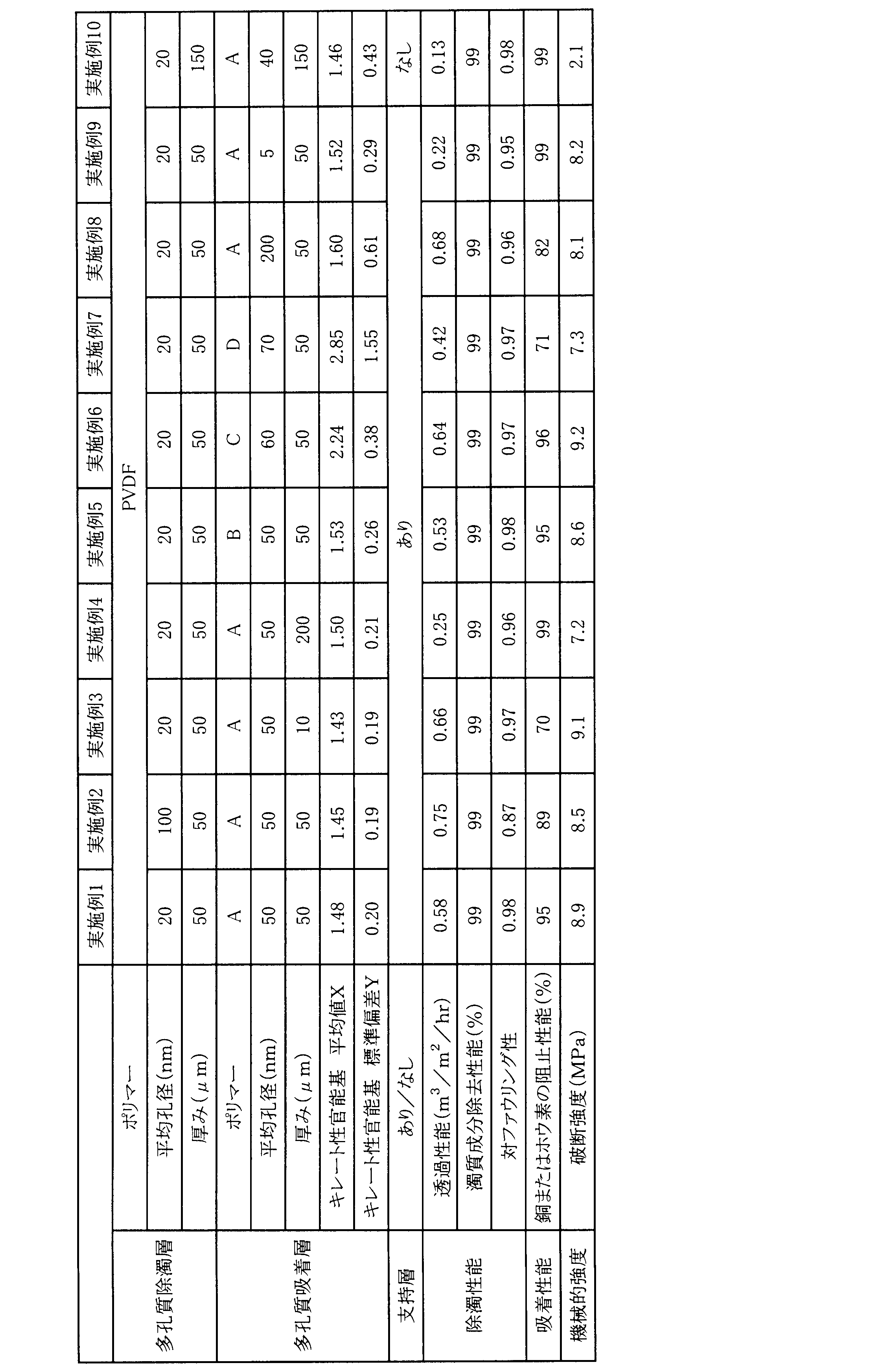
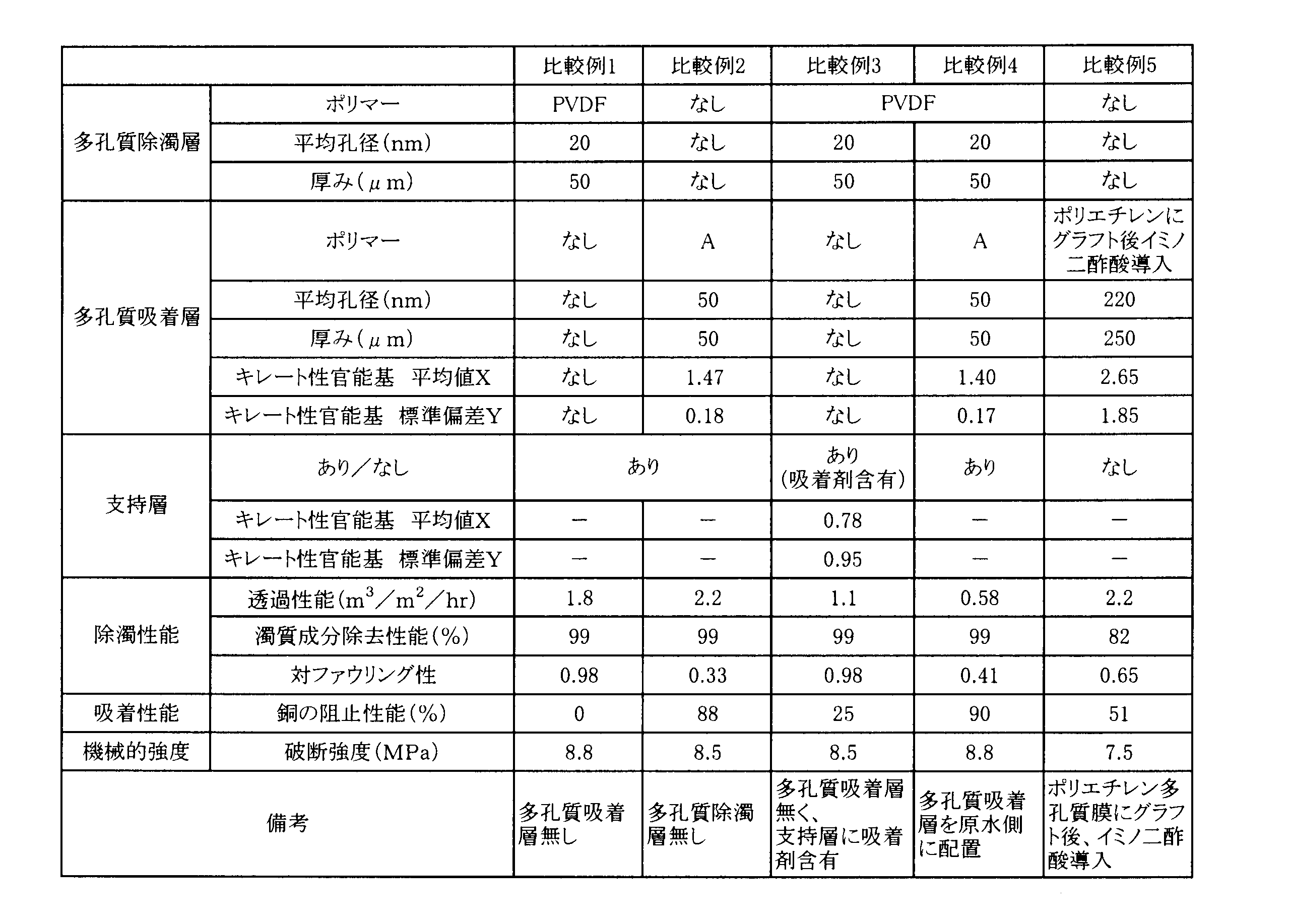
Claims (9)
- キレート性官能基を有するポリマーで実質的に構成される多孔質吸着層と、
前記多孔質吸着層よりも原水側に配された多孔質除濁層と
を備える多層分離膜。 - 前記多孔質吸着層の細孔の平均孔径Aと前記多孔質除濁層の表面の平均孔径Bが、A>Bである、請求項1に記載の多層分離膜。
- 前記多孔質吸着層の厚みが10μm以上500μm以下である、請求項1または請求項2に記載の多層分離膜。
- 前記多孔質吸着層は、前記キレート性官能基を有するポリマーが均一に分散した層であり、
前記多孔質吸着層の断面をエネルギー分散型X線分析で元素分析した際のキレート性官能基由来原子の原子数(%)の平均値Xと標準偏差YがX≧3Yを満たす、請求項1~請求項3のいずれか1項に記載の多層分離膜。 - 前記キレート性官能基由来原子が、N、O、P、S、NaおよびKからなる群から選ばれる少なくとも一種である、請求項4に記載の多層分離膜。
- さらに支持層を有する、請求項1~請求項5のいずれか1項に記載の多層分離膜。
- 50kPa、25℃における純水透過性能が0.10m3/m2・hr以上10m3/m2・hr以下、破断強度が6MPa以上、破断伸度が10%以上である、請求項1~請求項6のいずれか1項に記載の多層分離膜。
- 前記多孔質吸着層が、熱誘起相分離法および/または非溶媒誘起相分離法で得られた層である、請求項1~請求項7のいずれか1項に記載の多層分離膜。
- 前記多孔質除濁層が、熱誘起相分離法および/または非溶媒誘起相分離法で得られた層である、請求項1~請求項8のいずれか1項に記載の多層分離膜。
Priority Applications (4)
| Application Number | Priority Date | Filing Date | Title |
|---|---|---|---|
| KR1020167015147A KR102265728B1 (ko) | 2013-12-13 | 2014-11-27 | 다층 분리막 |
| US15/103,591 US10040033B2 (en) | 2013-12-13 | 2014-11-27 | Multilayer separation membrane |
| CN201480068378.3A CN105828921B (zh) | 2013-12-13 | 2014-11-27 | 多层分离膜 |
| JP2014557653A JP6413768B2 (ja) | 2013-12-13 | 2014-11-27 | 多層分離膜 |
Applications Claiming Priority (2)
| Application Number | Priority Date | Filing Date | Title |
|---|---|---|---|
| JP2013-257756 | 2013-12-13 | ||
| JP2013257756 | 2013-12-13 |
Publications (1)
| Publication Number | Publication Date |
|---|---|
| WO2015087702A1 true WO2015087702A1 (ja) | 2015-06-18 |
Family
ID=53371014
Family Applications (1)
| Application Number | Title | Priority Date | Filing Date |
|---|---|---|---|
| PCT/JP2014/081322 Ceased WO2015087702A1 (ja) | 2013-12-13 | 2014-11-27 | 多層分離膜 |
Country Status (5)
| Country | Link |
|---|---|
| US (1) | US10040033B2 (ja) |
| JP (1) | JP6413768B2 (ja) |
| KR (1) | KR102265728B1 (ja) |
| CN (1) | CN105828921B (ja) |
| WO (1) | WO2015087702A1 (ja) |
Cited By (2)
| Publication number | Priority date | Publication date | Assignee | Title |
|---|---|---|---|---|
| JP2023516926A (ja) * | 2020-02-25 | 2023-04-21 | インテグリス・インコーポレーテッド | リガンド修飾フィルターおよび液体組成物から金属を減少させるための方法 |
| JP2023545110A (ja) * | 2020-10-09 | 2023-10-26 | インテグリス・インコーポレーテッド | 精製水を生成するための濾過膜、システム、および方法 |
Families Citing this family (8)
| Publication number | Priority date | Publication date | Assignee | Title |
|---|---|---|---|---|
| JP2015202443A (ja) * | 2014-04-11 | 2015-11-16 | 住友電気工業株式会社 | 油水分離処理システム及び油水分離処理方法 |
| US10799837B2 (en) * | 2016-01-29 | 2020-10-13 | Toray Industries, Inc. | Separation membrane |
| WO2017196656A1 (en) * | 2016-05-13 | 2017-11-16 | 3M Innovative Properties Company | Multilayer articles including coatings on microfiltration membrane substrates and methods of making same |
| JP7031577B2 (ja) * | 2017-04-04 | 2022-03-08 | 東レ株式会社 | 多孔質繊維および吸着カラム |
| WO2020163181A1 (en) * | 2019-02-08 | 2020-08-13 | Entegris, Inc. | Ligand-modified filter and methods for reducing metals from liquid compositions |
| CN110201544B (zh) * | 2019-06-17 | 2022-01-07 | 万华化学集团股份有限公司 | 一种高通量高选择性纳滤膜及其制备方法 |
| CN111640527A (zh) * | 2020-06-10 | 2020-09-08 | 苏州登石新材科技有限公司 | 水溶性胶体、导电薄膜及其制备方法 |
| CN116618029B (zh) * | 2023-05-25 | 2025-11-11 | 上海交通大学 | 一种基于热致相分离法的高孔隙率偕胺肟基微球制备及其重金属吸附应用 |
Citations (9)
| Publication number | Priority date | Publication date | Assignee | Title |
|---|---|---|---|---|
| JPH0368425A (ja) * | 1989-08-07 | 1991-03-25 | Asahi Chem Ind Co Ltd | イオンの除去方法 |
| JPH0394883A (ja) * | 1989-06-26 | 1991-04-19 | Asahi Chem Ind Co Ltd | 複数の重金属イオンを同時に除去する方法 |
| JPH05309243A (ja) * | 1992-05-08 | 1993-11-22 | Asahi Chem Ind Co Ltd | 再生処理方法 |
| JP2008105016A (ja) * | 2006-09-26 | 2008-05-08 | Toray Ind Inc | ポリフッ化ビニリデン系樹脂からなる中空糸膜およびその製造方法 |
| JP2010227757A (ja) * | 2009-03-26 | 2010-10-14 | Toray Ind Inc | 複合分離膜 |
| JP2011016116A (ja) * | 2009-07-10 | 2011-01-27 | Asahi Kasei Chemicals Corp | 中空糸膜モジュール |
| WO2012105397A1 (ja) * | 2011-01-31 | 2012-08-09 | 東レ株式会社 | 水処理用分離膜およびその製造方法 |
| JP2012161741A (ja) * | 2011-02-07 | 2012-08-30 | Fujifilm Corp | 結晶性ポリマー微孔性膜及びその製造方法、並びに濾過用フィルタ |
| JP2013151671A (ja) * | 2011-12-28 | 2013-08-08 | Daikin Industries Ltd | 高分子多孔質膜 |
Family Cites Families (16)
| Publication number | Priority date | Publication date | Assignee | Title |
|---|---|---|---|---|
| US4612122A (en) * | 1981-06-29 | 1986-09-16 | Clara Ambrus | Removing heavy metal ions from blood |
| JPS58205543A (ja) | 1982-05-26 | 1983-11-30 | Japan Atom Energy Res Inst | ウラン吸着材およびその製造方法 |
| JPS6090243A (ja) * | 1983-10-25 | 1985-05-21 | Nitto Boseki Co Ltd | 小球状モノアリルアミン橋かけ重合体の製造方法 |
| US4927540A (en) * | 1986-09-04 | 1990-05-22 | The Dow Chemical Company | Ionic complex for enhancing performance of water treatment membranes |
| US5087372A (en) | 1989-03-24 | 1992-02-11 | Asahi Kasei Kogyo Kabushiki Kaisha | Method for removing heavy metal ions from contaminated water and a porous membrane usable therefor |
| JPH0483532A (ja) | 1990-07-27 | 1992-03-17 | Toray Ind Inc | 脱酸素繊維 |
| JP3312634B2 (ja) | 1993-07-08 | 2002-08-12 | 旭化成株式会社 | キレート型イオン吸着膜および製造方法 |
| KR20020042653A (ko) * | 1999-08-25 | 2002-06-05 | 비핀 에스. 파레 | 중성 pH 용액용 여과 및 정제 시스템 |
| JP2005074378A (ja) | 2003-09-03 | 2005-03-24 | Japan Atom Energy Res Inst | 井戸水中に溶存する重金属を除去する方法 |
| DE10344820B4 (de) * | 2003-09-26 | 2009-04-16 | Sartorius Stedim Biotech Gmbh | Adsorptionsmembranen, Verfahren zur Herstellung derselben und Verwendung der Adsorptionsmembranen in Vorrichtungen |
| JP4637737B2 (ja) | 2005-12-16 | 2011-02-23 | 株式会社日本海水 | ホウ素吸着剤の再生方法 |
| CN101472671B (zh) * | 2006-06-27 | 2012-05-23 | 东丽株式会社 | 聚合物分离膜及其制备方法 |
| AU2006346599B8 (en) * | 2006-07-25 | 2011-06-09 | Toray Industries, Inc. | Fluororesin polymer separation membrane and process for producing the same |
| CN102177627B (zh) * | 2008-10-10 | 2014-04-02 | 昭和电工株式会社 | 静电放电保护体 |
| US10369529B2 (en) * | 2012-01-30 | 2019-08-06 | California Institute Of Technology | Mixed matrix membranes with embedded polymeric particles and networks and related compositions, methods, and systems |
| JP6613892B2 (ja) * | 2014-07-07 | 2019-12-04 | 東レ株式会社 | 分離膜およびその製造方法 |
-
2014
- 2014-11-27 CN CN201480068378.3A patent/CN105828921B/zh not_active Expired - Fee Related
- 2014-11-27 KR KR1020167015147A patent/KR102265728B1/ko not_active Expired - Fee Related
- 2014-11-27 US US15/103,591 patent/US10040033B2/en active Active
- 2014-11-27 WO PCT/JP2014/081322 patent/WO2015087702A1/ja not_active Ceased
- 2014-11-27 JP JP2014557653A patent/JP6413768B2/ja not_active Expired - Fee Related
Patent Citations (9)
| Publication number | Priority date | Publication date | Assignee | Title |
|---|---|---|---|---|
| JPH0394883A (ja) * | 1989-06-26 | 1991-04-19 | Asahi Chem Ind Co Ltd | 複数の重金属イオンを同時に除去する方法 |
| JPH0368425A (ja) * | 1989-08-07 | 1991-03-25 | Asahi Chem Ind Co Ltd | イオンの除去方法 |
| JPH05309243A (ja) * | 1992-05-08 | 1993-11-22 | Asahi Chem Ind Co Ltd | 再生処理方法 |
| JP2008105016A (ja) * | 2006-09-26 | 2008-05-08 | Toray Ind Inc | ポリフッ化ビニリデン系樹脂からなる中空糸膜およびその製造方法 |
| JP2010227757A (ja) * | 2009-03-26 | 2010-10-14 | Toray Ind Inc | 複合分離膜 |
| JP2011016116A (ja) * | 2009-07-10 | 2011-01-27 | Asahi Kasei Chemicals Corp | 中空糸膜モジュール |
| WO2012105397A1 (ja) * | 2011-01-31 | 2012-08-09 | 東レ株式会社 | 水処理用分離膜およびその製造方法 |
| JP2012161741A (ja) * | 2011-02-07 | 2012-08-30 | Fujifilm Corp | 結晶性ポリマー微孔性膜及びその製造方法、並びに濾過用フィルタ |
| JP2013151671A (ja) * | 2011-12-28 | 2013-08-08 | Daikin Industries Ltd | 高分子多孔質膜 |
Cited By (3)
| Publication number | Priority date | Publication date | Assignee | Title |
|---|---|---|---|---|
| JP2023516926A (ja) * | 2020-02-25 | 2023-04-21 | インテグリス・インコーポレーテッド | リガンド修飾フィルターおよび液体組成物から金属を減少させるための方法 |
| JP2025072377A (ja) * | 2020-02-25 | 2025-05-09 | インテグリス・インコーポレーテッド | リガンド修飾フィルターおよび液体組成物から金属を減少させるための方法 |
| JP2023545110A (ja) * | 2020-10-09 | 2023-10-26 | インテグリス・インコーポレーテッド | 精製水を生成するための濾過膜、システム、および方法 |
Also Published As
| Publication number | Publication date |
|---|---|
| US20160310907A1 (en) | 2016-10-27 |
| US10040033B2 (en) | 2018-08-07 |
| CN105828921B (zh) | 2018-05-11 |
| JPWO2015087702A1 (ja) | 2017-03-16 |
| JP6413768B2 (ja) | 2018-10-31 |
| KR20160097205A (ko) | 2016-08-17 |
| CN105828921A (zh) | 2016-08-03 |
| KR102265728B1 (ko) | 2021-06-16 |
Similar Documents
| Publication | Publication Date | Title |
|---|---|---|
| JP6413768B2 (ja) | 多層分離膜 | |
| CN101472671B (zh) | 聚合物分离膜及其制备方法 | |
| AU2012294783B2 (en) | Polymer blend membranes | |
| US9174174B2 (en) | Separation membrane and method for producing the same | |
| Baig et al. | Designing of nanotextured inorganic-organic hybrid PVDF membrane for efficient separation of the oil-in-water emulsions | |
| KR102526940B1 (ko) | 다공질막, 막 모듈, 수 처리 장치, 및 다공질막의 제조 방법 | |
| KR101217070B1 (ko) | 폴리머 섬유체, 그 제조 방법 및 유체 여과용 필터 | |
| KR102065159B1 (ko) | 불소중합체 및 불소중합체를 포함한 막(ii) | |
| JP4626319B2 (ja) | 多孔質膜およびその製造方法、固液分離装置 | |
| Aksoy et al. | Fabrication of gas-permeable polyvinylidene fluoride (PVDF) hollow-fiber membrane by dry-jet wet spinning and its application in membrane biofilm reactors | |
| JP2019130522A (ja) | 中空糸膜、中空糸膜の製造方法、および中空糸膜を用いたビール、ワインまたは日本酒の製造方法 | |
| JP6767141B2 (ja) | ポリフッ化ビニリデン製多孔膜とその製造方法 | |
| WO2009119373A1 (ja) | 中空糸膜およびその製造方法 | |
| CN101500695A (zh) | 氟树脂聚合物分离膜及其制备方法 | |
| JP2017001029A (ja) | 多層分離膜 | |
| Mahdavi et al. | RETRACTED: Fabrication of PVDF mixed matrix nanofiltration membranes incorporated with TiO2 nanoparticles and an amphiphilic PVDF‐g‐PMMA copolymer | |
| JPS63240902A (ja) | 処理方法 | |
| KR100694895B1 (ko) | 기능성 직물 여과재 및 이의 제조방법 | |
| JP2018015734A (ja) | 吸着剤含有分離膜およびその製造方法 | |
| Chowdhury et al. | Synthesis and characterization of silver nanoparticle incorporated copolymer composite membrane for polymer enhanced ultrafiltration of hexavalent chromium ions from water | |
| Ovando‐Medina et al. | Synthesis of sulfonated poly (styrene‐co‐methyl methacrylate) by semicontinuous heterophase polymerization for filtration membranes | |
| WO2022071243A1 (ja) | 吸着材 | |
| CN112973467A (zh) | 一种复合纳滤膜的制备方法及复合纳滤膜 | |
| Kumar et al. | Polymeric Membranes for Separation and Purification Applications | |
| Back et al. | Diclofenac removal and fouling behaviour of multi-channel mixed matrix membranes (MCMMM) with activated carbon |
Legal Events
| Date | Code | Title | Description |
|---|---|---|---|
| ENP | Entry into the national phase |
Ref document number: 2014557653 Country of ref document: JP Kind code of ref document: A |
|
| 121 | Ep: the epo has been informed by wipo that ep was designated in this application |
Ref document number: 14870425 Country of ref document: EP Kind code of ref document: A1 |
|
| ENP | Entry into the national phase |
Ref document number: 20167015147 Country of ref document: KR Kind code of ref document: A |
|
| WWE | Wipo information: entry into national phase |
Ref document number: 15103591 Country of ref document: US |
|
| NENP | Non-entry into the national phase |
Ref country code: DE |
|
| 122 | Ep: pct application non-entry in european phase |
Ref document number: 14870425 Country of ref document: EP Kind code of ref document: A1 |