WO2015080228A1 - マスク - Google Patents
マスク Download PDFInfo
- Publication number
- WO2015080228A1 WO2015080228A1 PCT/JP2014/081469 JP2014081469W WO2015080228A1 WO 2015080228 A1 WO2015080228 A1 WO 2015080228A1 JP 2014081469 W JP2014081469 W JP 2014081469W WO 2015080228 A1 WO2015080228 A1 WO 2015080228A1
- Authority
- WO
- WIPO (PCT)
- Prior art keywords
- mask
- main body
- welded
- portions
- mask body
- Prior art date
- Legal status (The legal status is an assumption and is not a legal conclusion. Google has not performed a legal analysis and makes no representation as to the accuracy of the status listed.)
- Ceased
Links
Images





Classifications
-
- A—HUMAN NECESSITIES
- A41—WEARING APPAREL
- A41D—OUTERWEAR; PROTECTIVE GARMENTS; ACCESSORIES
- A41D13/00—Professional, industrial or sporting protective garments, e.g. surgeons' gowns or garments protecting against blows or punches
- A41D13/05—Professional, industrial or sporting protective garments, e.g. surgeons' gowns or garments protecting against blows or punches protecting only a particular body part
- A41D13/11—Protective face masks, e.g. for surgical use, or for use in foul atmospheres
- A41D13/1107—Protective face masks, e.g. for surgical use, or for use in foul atmospheres characterised by their shape
- A41D13/1115—Protective face masks, e.g. for surgical use, or for use in foul atmospheres characterised by their shape with a horizontal pleated pocket
-
- A—HUMAN NECESSITIES
- A41—WEARING APPAREL
- A41D—OUTERWEAR; PROTECTIVE GARMENTS; ACCESSORIES
- A41D13/00—Professional, industrial or sporting protective garments, e.g. surgeons' gowns or garments protecting against blows or punches
- A41D13/05—Professional, industrial or sporting protective garments, e.g. surgeons' gowns or garments protecting against blows or punches protecting only a particular body part
- A41D13/11—Protective face masks, e.g. for surgical use, or for use in foul atmospheres
- A41D13/1161—Means for fastening to the user's head
Definitions
- the present invention relates to a mask used for protection from cold viruses, pollen, dust, PM2.5, and the like.
- N95 mask is known as a mask for countermeasures against fine particulate matter, but there are problems such as high price, poor design, and suffocation. Therefore, a mask that is a general mask and has improved adhesion between the side portion of the mask main body and the face is desired in order to suppress intrusion of PM2.5.
- the N95 mask is a mask that has cleared the N95 standard of the National Institute of Occupational Safety and Health (NIOSH) and has been approved.
- Patent Document 1 discloses a mask body portion that has been pleated in the horizontal direction and a line ( A string-like or belt-like ear-hook member, and one end and the other end of the ear-hook member are predetermined such that a tensile force by the ear-hook member acts on the outside in the vertical direction of the mask main body when the mask is mounted. There is disclosed a mask that is attached at intervals to suppress the bending of the lateral end portion of the mask main body at the time of wearing, thereby improving the adhesion between the side of the mask main body and the face.
- the present invention has been made in view of the above problems, and when attached, the side portion of the mask body adheres well to the face, and a gap is not formed between the mask body and the face. It is an object of the present invention to provide a mask that can suppress entry of fine particles into the surface.
- a mask comprising a mask body and ear hooks formed at both lateral ends of the mask body, wherein a plurality of pleats are formed by overlapping a part of the mask body, The plurality of pleats are stopped by welds formed by heat sealing, The welded portion is formed in a straight line at equal intervals in the vertical direction on both sides in the horizontal direction of the mask body, A mask characterized in that an interval between adjacent welds is 3 mm or more.
- the side tape is made of the same material as the ear hook, The mask according to (2), wherein the ear hook is attached to the side tape.
- a lateral weld portion formed by heat sealing is formed, extending in the lateral direction of the mask body, The mask according to any one of (1) to (7), wherein an interval between the weld portions in the vertical direction is larger than an interval between the horizontal weld portions in the horizontal direction.
- the mask body is provided with side blocks so as to cover a gap between the face and the mask body at both lateral ends on the side of the mask body that contacts the face of the wearer.
- the mask main body is provided with a chin receiving pocket for receiving the chin of the wearer at a lower end portion of the mask main body on the side contacting the wearer's face (1).
- both end portions in the horizontal direction of the mask main body are worn. It is easy to follow the shape of the person's face (hereinafter also referred to as shape familiarity), and the gap between the side of the mask body and the face is reduced and the adhesion is increased, effectively preventing fine particles from entering the mask. Can be suppressed.
- shape familiarity the shape of the person's face
- the mask as described in said (2) since the both ends of the mask main body of the mask body are covered with the side tape, the fluff of the cut surface of a mask main body can be suppressed, and the touch can be improved.
- the ear hooking portion since the ear hooking portion is attached to the side tape made of the same material, the ear hooking portion can be firmly attached by melting the same material by heat sealing. .
- the shape conformability deteriorates.
- the pleats can be easily manufactured by temporarily fixing, and the number of the temporary welded portions is less than the number of the welded portions, so that the shape weldability is improved by the temporary welded portions. Inhibition can be suppressed.
- the mask described in the above (6) it is possible to suppress deterioration in shape conformability due to the temporary welded portion by causing at least a part of the temporary welded portion to overlap the welded portion.
- the mask described in the above (7) it is possible to suppress deterioration in shape conformability due to the temporary welded portion by setting the minimum interval between the temporary welded portions to be larger than the interval between the welded portions.
- the interval between the longitudinal welded portion and the lateral welded portion is aligned, and the shape conformability is improved by deliberately increasing the interval between the longitudinal welded portions. Can do.
- the adhesion between the side of the mask body and the face can be further improved, and the entry of fine particles into the mask can be further suppressed.
- the adhesiveness of the lower end part of a mask main body and a face can be improved further, and the penetration
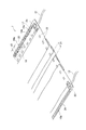
- FIG. 1 is a perspective view of the inside of a mask according to the first embodiment of the present invention.
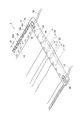
- FIG. 2 is an enlarged view of an end portion in the horizontal direction when the mask of the first embodiment is viewed from the inside.
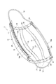
- FIG. 3 is a perspective view of the inside of the mask according to the second embodiment of the present invention.
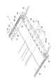
- FIG. 4 is an enlarged view of an end portion in the horizontal direction when the mask of the second embodiment is viewed from the inside.
- FIG. 5 is a perspective view of the inside of the mask according to the third embodiment of the present invention.
- FIG. 6 is an enlarged view of the end portion in the horizontal direction when the mask of the third embodiment is viewed from the inside.
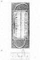
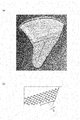
- FIG. 7A is a diagram showing a photograph of the mask of Example 1, and FIG.
- FIG. 7B is a schematic diagram showing an enlarged lateral end portion of the mask of FIG. 7A.
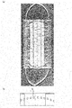
- FIG. 8A is a diagram showing a photograph of the mask of Example 2
- FIG. 8B is a schematic diagram showing an enlarged end portion in the horizontal direction of the mask of FIG. 8A.
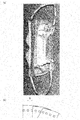
- FIG. 9A is a view showing a photograph of the mask of Comparative Example 1
- FIG. 9B is a schematic view showing an enlarged lateral end portion of the mask of FIG. 9A.
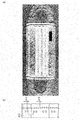
- FIG. 10A is a view showing a photograph of the mask of Comparative Example 2
- FIG. 10B is a schematic view showing an enlarged lateral end portion of the mask of FIG. 10A.
- FIG. 11A is a view showing a photograph of the mask of Comparative Example 3, and FIG.
- FIG. 11B is a schematic view showing an enlarged lateral end portion of the mask of FIG. 11A.
- FIG. 12A is a diagram showing a photograph of the mask of Comparative Example 4
- FIG. 12B is a schematic diagram showing an enlarged end portion in the horizontal direction of the mask of FIG.
- FIG. 13A is a view showing a photograph of the mask of Comparative Example 5
- FIG. 13B is a schematic view showing an enlarged lateral end portion of the mask of FIG. 13A.
- FIG. 14 is a diagram illustrating a state where the wearer actually wears the mask according to the first embodiment.
- FIG. 15 is a diagram showing a state in which the wearer actually wears the mask of Comparative Example 2.
- FIG. 1 is a perspective view showing a state in which the center portion is vertically expanded and curved in the width direction so that the mask is actually worn, and is viewed from the side in contact with the wearer's face (the inside of the mask). It is.
- FIG. 2 is an enlarged view of a lateral end portion inside the mask.
- the mask 1 As shown in FIGS. 1 and 2, the mask 1 according to the first embodiment includes a mask body 10 that covers the wearer's nose and mouth when worn, and a width direction of the mask body 10 (hereinafter referred to as a lateral direction). Ear straps 12 serving as ear hooks formed at both ends are provided.
- the material constituting the mask main body 10 is preferably a non-woven fabric manufactured using polyester fiber, polypropylene fiber, polyethylene fiber, nylon fiber, cotton fiber, or the like as a raw material.
- the ear strap 12 is made of a rubber material and a covering material covering the rubber material.
- the rubber material is preferably made of polyurethane fiber, thermoplastic elastomer or the like as a raw material.
- the covering material is preferably produced from polyester fiber, nylon fiber or the like.
- the mask 1 of the present embodiment is of a so-called “pleated type”, and the mask body 10 is constituted by a plurality of non-woven fabrics stacked, and a plurality (four in the figure) of lateral folds 14 are formed. As a result, the mask body 10 partially overlaps to form a plurality of pleats 15.
- the mask body 10 is shown as being composed of a single nonwoven fabric, but in practice, a plurality of nonwoven fabrics are overlapped (hereinafter referred to as FIGS. 3 to 6). The same applies to the above).
- the upper end portion 10a of the mask body 10 is folded inside the mask body 10 over the entire horizontal direction.
- the folded portion is formed in two rows linearly along the horizontal direction by heat sealing, and a mesh seal 17 formed in a net shape so as to extend linearly along the horizontal direction by heat sealing.
- the horizontal welded portions 16a and 16b are fixed.
- the laterally welded portions 16a and 16b are formed in parallel at equal intervals, and a part of the laterally welded portion 16a located at the upper portion overlaps the mesh seal 17 formed in a mesh shape by heat sealing.
- heat sealing welding
- high frequency or ultrasonic waves may be used.
- the mesh seal means that each row of welding points arranged in two rows is welded at an equal pitch (interval), and the row adjacent to one row is at the same pitch at a position half the pitch. It is welded and means a seal portion formed by providing two or more sets of two rows as one set.
- a bag-shaped accommodation space 18 is formed in the upper end portion 10a of the mask body 10 inside the one end side of the mask body 10 by the laterally welded portions 16a and 16b.
- a nose fit member 20 that is deformed in accordance with the shape is accommodated.
- the nose fit member 20 is preferably in close contact with the shape of the nose and can maintain the shape, and may be made of resin such as polyester, or may be metallic such as iron or aluminum.
- the lower end portion 10b of the mask main body 10 is folded back inside the mask main body 10 over the entire horizontal direction and fixed by a mesh seal 24 so as to extend linearly along the horizontal direction. Further, the end portion of the ear strap 12 is also fixed to the corner end portion of the mask main body 10 by a mesh seal 25.
- the plurality of pleats 15 are stopped by a plurality of welds 22 formed by heat sealing on both sides of the mask body 10 in the lateral direction.
- the welded portion 22 and the mask main body 10 are linearly formed at equal intervals in the direction orthogonal to the horizontal direction (hereinafter referred to as the vertical direction) on both sides in the horizontal direction.
- the distance d1 between the welded portions 22 adjacent in the longitudinal direction is formed to be at least 3 mm, preferably 4 mm, more preferably 5 mm.
- the interval d1 between the weld portions 22 adjacent in the vertical direction is formed to be larger than the interval d0 between the horizontal weld portions adjacent in the horizontal direction of the horizontal weld portions 16a and 16b.
- the welding part 22 is formed in 1 row.
- the center-to-center distance between the adjacent welded portions 22 is preferably 5 mm or more, more preferably 6 mm or more, and further preferably 7 mm or more.
- the interval d1 between the adjacent welded portions 22 is welded in the lateral direction.
- the mesh seal is not adopted, and the distance d1 between the adjacent welded portions 22 is deliberately wide, particularly 3 mm or more, in order to form the same as the distance d0 between the portions 16a and 16b.
- the conformability of the mask body 10 to the wearer's face can be improved.
- the upper limit value of the interval d1 between the adjacent welded portions 22 is not particularly limited as long as it is within a range in which the pleats 15 can be stopped.
- the two ear straps 12 of the mask 1 are wound around the wearer's ears, and the nose fitting member 20 is bent in accordance with the shape of the nasal bridge to Wear while keeping 10a in close contact with the face.
- the pleats 15 of the mask main body 10 are stretched at the center, thereby covering the wearer's nose and mouth.
- both ends of the mask body 10 in the horizontal direction receive tension from the ear straps 12, as described above, in the welded portions 22 formed on both sides of the mask body 10 in the lateral direction, the interval between the adjacent welded portions 22 is 3 mm. Since the above is ensured, the both ends of the mask body 10 in the horizontal direction are likely to follow the shape of the wearer's face.
- the vertical interval between the welded portions 22 formed on both sides of the mask body 10 in the horizontal direction is wide, and the interval between the adjacent welded portions 22 is 3 mm or longer. Since it is formed in a straight line in the direction, the familiarity of the shape of the mask body 10 with respect to the wearer's face is good, the gap between the side of the mask body 10 and the face is reduced, and the adhesion is increased. Intrusion of fine particles can be effectively suppressed.
- a collection filter for preventing the entry of fine particles may be incorporated in the mask body 10.
- the collection filter it is possible to more effectively suppress the entry of fine particles into the mask.
- FIG. 3 and 4 show a mask according to the second embodiment of the present invention.
- FIG. 3 is a perspective view of the inside of the mask according to the second embodiment.
- FIG. 4 is an enlarged view of a lateral end portion inside the mask.
- the same components as those of the mask 1 of the first embodiment shown in FIGS.
- the mask 2 of the second embodiment is the side of the mask 1 of the first embodiment that is provided on both sides of the mask body 10 so as to cover both lateral ends. Tapes 30 and 30 are provided.
- the some pleat 15 formed so that a part of nonwoven fabric may overlap may be temporarily fixed by the temporary welding part 36 in a horizontal direction edge part, respectively.
- the temporary welding portions 36 are formed side by side in the horizontal direction at each position in the vertical direction where the pleats 15 are temporarily fixed. By temporarily fixing the pleats 15 in this way, the pleats 15 can be easily manufactured.
- the side tapes 30, 30 are preferably manufactured using polyester fiber, polypropylene fiber, polyethylene fiber, nylon fiber, or the like as raw materials.
- the side tapes 30, 30 are arranged at both lateral ends of the mask body 10 from the front surface to the rear surface of the mask body 10. In a state of being folded back toward the end, it is attached so as to cover the end of the temporarily fixed pleat 15.
- the side tapes 30 and 30 are welded so as to overlap the mask main body 10 by the welded portions 22 formed in a row in the vertical direction.
- the ear straps 12 are attached to the mask body 10 by melting the same materials. On the other hand, it can be fixed more firmly.
- the ear strap 12 is made of a rubber material and a covering material
- the side tapes 30 and 30 are preferably made of the same material as the covering material.
- the temporary welding part 36 is arrange
- the welded portion 22 does not employ a mesh seal, and further has a wider distance d1 between the adjacent welded portions 22 than the distance d0 between the lateral welded portions 16a and 16b so as to be particularly 3 mm or more. Is also the same as the mask 1 of the first embodiment.
- the number of the temporary welding parts 36 is formed to be smaller than the number of the welding parts 22. Thus, by making the number of the temporary welding parts 36 smaller than the number of the welding parts 22, it is possible to suppress the shape conformability from being inhibited by the temporary welding parts 36.
- the temporary welding portions 36 do not have to be formed side by side in the horizontal direction, and may be formed in a row in the vertical direction.
- the temporary welded portion 36 in order to prevent the shape conformability from being hindered by the temporary welded portion 36, it is preferable to match the positions of the temporary welded portion 36 and the welded portion 22 in the vertical direction as much as possible. Therefore, as shown in FIG. 4, at least a part of the temporary welding portion 36 is formed so as to overlap the welding portion 22 in the vertical direction.
- the intervals d2 and d3 between the adjacent temporary welding portions 36 in the vertical direction are formed to be larger than the interval between the welding portions 22.
- the distances d2 and d3 between the temporary welded portions 36 may be the same or larger, but by forming the minimum distance between adjacent temporary welded portions 36 to be larger than the distance between the welded portions 22, It is possible to suppress the shape conformability from being deteriorated by the portion 36.
- the mask body 10 is covered with the side tapes 30 and 30 at both lateral ends of the mask body 10.
- the fluff of the cut surface can be suppressed and the touch can be improved.
- the ear strap 12 can be more firmly fixed to the mask body 10.
- the provisional weld portion 36 facilitates the manufacture of the pleat 15. Furthermore, by making the minimum interval of the temporary welded portion 36 larger than the interval of the welded portion 22, it is possible to suppress the shape conformability from being deteriorated by the temporary welded portion 36.
- FIG. 5 and 6 show a mask according to the third embodiment of the present invention.
- FIG. 5 is a perspective view of the inside of the mask according to the third embodiment.
- FIG. 6 is an enlarged view of a lateral end portion inside the mask.
- symbol is attached
- the mask 3 of the third embodiment covers the gap between the wearer's face and the mask body 10 at both lateral ends of the mask body 10 in the mask 2 of the second embodiment.
- the side block 32, 32 or the lower end of the mask body 10 is provided with a chin receiving pocket 34 for receiving the wearer's chin.
- both the side blocks 32 and 32 and the jaw receiving pocket 34 are provided, but a mask provided with either one corresponds to this embodiment.
- the side blocks 32, 32 are formed by sandwiching one end of a side barrier tape 31 formed in a wide band shape between the mask main body 10 and the side tape 30, and the jaw storing pocket 34 is the lower end of the mask main body 10.
- the portion 10b is formed by being largely folded inward.
- the side block 32 (side barrier tape 31) is positioned above the jaw receiving pocket 34, that is, on the side that contacts the wearer's face (inside the mask).
- the side barrier tape 31 can more effectively suppress the entry of fine particles into the mask by using a non-breathable material such as a polyethylene terephthalate film, a polypropylene film, or a polyethylene film.
- the weld portion 22 is formed by heat-sealing from the side tape 30 together.
- the side barrier tape 31 has an upper end fixed by a mesh seal 17 and a lower end fixed by a mesh seal 25.
- a mesh seal 25 for attaching the ear strap 12 is also formed from above.
- the side blocks 32 and 32 are formed by fixing the right (or left) end by the welded portion 22 and fixing the upper and lower ends by the mesh seals 17 and 24, respectively.
- the jaw storing pocket 34 is formed in a pocket shape by fixing both left and right ends by the welded portion 22 and fixing the lower end by the mesh seal 24.
- the left and right side blocks 32, 32 stand up with respect to the mask body 10 by extending the pleats 15 of the mask body 10 or housing the wearer's chin in the jaw housing pocket 34. .
- the gap between the mask body 10 and the face is completely covered, the adhesion can be further improved, and the entry of fine particles into the mask can be further suppressed.
- the welded portion 22 does not employ a mesh seal, and further, the interval d1 between adjacent welded portions 22 is wide, particularly, the interval between the lateral welded portions 16a and 16b so as to be 3 mm or more. It is the same as the mask 1 of the first embodiment in that it is formed wider than d0.
- the mask body 10 and the face are provided by including the side blocks 32 and 32 and the jaw storage pocket 34. The gap is completely covered, the adhesion can be further improved, and the intrusion of fine particles into the mask can be further suppressed.
- 7 to 13 are (a) a photograph of a mask taken from the inside or the outside, and (b) a schematic view showing an enlarged lateral end of the mask of (a).
- FIG. 7 shows a mask of Example 1 of the present invention, which is a mask having almost the same form as the mask shown in FIGS. 3 and 4 provided with a side tape as in the second embodiment.
- FIG. 8 shows a mask according to Example 2 of the present invention, as shown in FIGS. 5 and 6, which includes a side tape, a side block, and a jaw receiving pocket as in the third embodiment.
- the mask has almost the same shape as the mask.
- 9 is a product of Company A (hereinafter referred to as Comparative Example 1)
- FIG. 10 is a product of Company B (hereinafter referred to as Comparative Example 2)
- FIG. 11 is a product of Company C (hereinafter referred to as Comparative Example 3)
- FIG. FIG. 13 shows a product 2 of C company (hereinafter referred to as Comparative Example 4)
- FIG. 13 shows a product of Company D (hereinafter referred to as Comparative Example 5), both of which are commercially available masks.
- the mask of Example 1 of the present invention shown in FIG. 7 and the mask of Example 2 of the present invention shown in FIG. 8 are in order of polypropylene nonwoven fabric, polypropylene nonwoven fabric, collection filter, and polypropylene nonwoven fabric from the outside to the inside.
- the welded portions on both sides in the horizontal direction of the mask body thus formed were formed in a straight line in a row at equal intervals in the vertical direction, and the interval d1 between adjacent welded portions in the vertical direction was about 5 mm. Further, the distance d1 and the like in the commercial mask of the comparative example were measured by applying a ruler to the actual mask.
- a plurality of pleats are formed on the mask body, and in addition to the nose fit member, a sponge that can be deformed in accordance with the shape of the mask wearer's nose inside the mask body.
- two pleats are formed in the vertical direction so that the lower end of the mask body is shorter than the upper end, and the welded portions on both sides in the horizontal direction of the mask main body are viewed from above by the vertical pleats. Although it is curved inwardly downward, it is linearly formed in one row at equal intervals in the vertical direction, and the interval d1 between adjacent welded portions in the vertical direction is about 2 mm.
- a plurality of pleats are formed on the mask body, and a nose fit member is provided on the upper end.
- the welded portions on both sides in the horizontal direction of the mask main body are formed in a substantially circular arc shape so that the central portion opens in the horizontal direction with respect to the upper end portion and the lower end portion in a line at equal intervals.
- a distance d1 between adjacent welds in the longitudinal direction was 2 mm.
- a plurality of pleats are formed on the mask body, and a nose fit member is provided on the upper end.
- the welded portions on both lateral sides of the mask body are located on the inner side in the lateral direction and the first welded portion that stops the pleats, and on the outer side in the lateral direction, the ear hooking portion is fastened to the mask body over the entire length of the lateral ends. It consists of two welds.
- the first welded portions are formed in a straight line in the longitudinal direction, and the interval d11 between adjacent welded portions is about 1.5 mm, d12 is about 6 mm, and both intervals are provided alternately.
- the second welded portion was formed in a straight line in one row at equal intervals in the vertical direction, and the interval d13 between adjacent welded portions in the vertical direction was about 1 mm.
- the pleat is not formed in the mask main body, the central welding part is formed along the vertical direction in the horizontal center of the mask main body, and the central welding part is forward when the mask is worn.
- a fitting member that fits the cheek is provided at the upper end of the mask body.
- a welded portion is formed by a mesh seal at the lateral end of the mask body to attach the ear hook to the mask body over the entire length of the lateral end.
- the mesh seal has 3.5 sets, that is, seven rows of welded portions, and the distance between the pitches of each row, that is, the interval d1 between the welded portions adjacent in the vertical direction is 1 mm.
- Comparative Example 5 shown in FIG. 13 a plurality of pleats are formed on the mask main body, the lateral end portions of the mask main body are covered with side tape, and the ear straps are fastened to the side tape. Temporary welds are formed at both lateral ends of the mask body covered with the side tape. Moreover, the side tape and the mask main body are overlapped and welded to each other on the inner side in the horizontal direction of the temporary welded portion by the welded portion. The welded portions were linearly formed in two rows at equal intervals in the vertical direction, and the interval d1 between adjacent welded portions in the vertical direction was about 0.5 mm.
- the JIS standard JIS T 8159: 2006 Respiratory protection device leakage rate test method
- a mask leak rate test was conducted based on the number of subjects in each case (2 adult males).
- the subject puts a mask into a chamber (test room) filled with NaCl, and performs actions such as standing still, turning his face left and right, moving up and down, and speaking.
- the concentration of NaCl in the mask is measured to see how much NaCl is sucked into the mask.
- the leakage rates of Examples 1 and 2 are very low compared to the leakage rates of Comparative Examples 1 to 5.
- the welded portions are linearly formed at equal intervals, and the distance between the adjacent welded portions is formed to be wide 5 mm, so that the mask lateral end portion becomes soft.
- the mask body has good shape familiarity to the wearer's face, the gap between the side of the mask body and the face is reduced, the adhesion is increased, and the intrusion of NaCl into the mask can be effectively suppressed. It is thought that.
- the leakage rate of the mask of Example 2 was improved compared to the mask of Example 1 because the gap between the mask body and the face was completely covered by the side block and the jaw storing pocket, and the contact was tight. It is considered that the property was increased and the intrusion of NaCl into the mask could be further suppressed.
- the mask leakage rate test as described above was performed on the masks of Example 1 and Example 2 with 8 adult male subjects.
- the leakage rate was very low even when the number of subjects was increased. From the above, it has been found that the shape familiarity of the mask of the present invention can sufficiently cope with differences in the size and shape of the wearer's face.
- FIG. 14 and FIG. 15 schematically show photographs comparing how much gap is generated on the side of the mask main body in a state where the mask is actually mounted.
- FIG. 14 is a diagram schematically showing a state in which the wearer actually wears the mask of Example 1 (FIG. 7) of the present invention.
- FIG. 15 is a diagram schematically showing a state in which the wearer actually wears the mask of Comparative Example 2 (FIG. 10).
- the side portion A of the mask body is familiar along the face surface, fits closely to the wearer's face, and almost no gap is seen. There wasn't.
- the side B of the mask body was bent at two locations B1 and B2, and a gap was formed at that portion. From the above, it is clear that the mask of the present invention has good shape conformability to the face of the wearer of the mask body.
- the mask of the present invention closely adheres to the wearer's face and suppresses the formation of gaps at the side of the mask body, and highly suppresses the entry of fine particles into the mask. Is possible.
Landscapes
- Health & Medical Sciences (AREA)
- General Health & Medical Sciences (AREA)
- Physical Education & Sports Medicine (AREA)
- Engineering & Computer Science (AREA)
- Textile Engineering (AREA)
- Respiratory Apparatuses And Protective Means (AREA)
Abstract
Description
(1) マスク本体と、該マスク本体の横方向両端部に形成された耳掛け部と、を備え、前記マスク本体の一部が重なることで複数のプリーツが形成されたマスクであって、
前記複数のプリーツは、ヒートシールによって形成された溶着部で止められており、
前記溶着部は、前記マスク本体の横方向両側で縦方向に等間隔で直線状に形成され、
隣り合う前記溶着部の間隔が3mm以上であることを特徴とするマスク。
(2) 前記マスク本体の横方向両端部は、サイドテープによって覆われていることを特徴とする(1)に記載のマスク。
(3) 前記サイドテープは、前記耳掛け部と同じ素材からなり、
前記耳掛け部が、前記サイドテープに取り付けられていることを特徴とする(2)に記載のマスク。
(4) 前記溶着部は、前記サイドテープと前記マスク本体とを重ね合わせてヒートシールすることで形成されたことを特徴とする(2)又は(3)に記載のマスク。
(5) 前記サイドテープで覆われた前記マスク本体の横方向両端部には、前記複数のプリーツがヒートシールによって仮止めされた仮溶着部が、前記溶着部よりも前記マスク本体の横方向で外側に形成されており、
前記縦方向における、前記仮溶着部の数は、前記溶着部の数よりも少ないことを特徴とする(2)~(4)のいずれかに記載のマスク。
(6) 前記仮溶着部の少なくとも一部は、前記溶着部と前記縦方向においてオーバーラップしていることを特徴とする(5)に記載のマスク。
(7) 前記縦方向における、隣り合う前記仮溶着部の最小間隔は、前記溶着部の間隔よりも大きいことを特徴とする(5)又は(6)に記載のマスク。
(8) 前記マスク本体の上端部及び下端部には、前記マスク本体の横方向に延びる、ヒートシールによって形成された横方向溶着部が形成され、
前記縦方向における前記溶着部の間隔は、前記横方向における前記横方向溶着部の間隔よりも大きいことを特徴とする(1)~(7)のいずれかに記載のマスク。
(9) 前記マスク本体には、前記マスク本体の着用者の顔面に当接する側の横方向両端部に前記顔面と前記マスク本体との隙間を覆うようにサイドブロックが設けられていることを特徴とする(1)~(8)のいずれかに記載のマスク。
(10) 前記マスク本体には、前記マスク本体の着用者の顔面に当接する側の下端部に前記着用者の顎部を収容する顎部収容ポケットが設けられていることを特徴とする(1)~(9)のいずれかに記載のマスク。
上記(2)に記載のマスクによれば、マスク本体の横方向両端部がサイドテープで覆われているため、マスク本体の裁断面の毛羽立ちを抑え、肌触りを良くすることができる。
上記(3)に記載のマスクによれば、耳掛け部をこれと同じ素材からなるサイドテープに取り付けるようにしたため、ヒートシールにより同じ素材が溶けあうことで耳掛け部を強固に取り付けることができる。
上記(4)に記載のマスクによれば、溶着部とは別にサイドテープをマスク本体に溶着すると形状馴染み性が悪化するところ、溶着部でサイドテープを溶着することで、形状馴染み性の悪化を防止することができる。
上記(5)に記載のマスクによれば、仮止めすることで、プリーツの製造が容易となり、また仮溶着部の数を溶着部の数より少なくすることで、仮溶着部によって形状馴染み性が阻害されるのを抑制することができる。
上記(6)に記載のマスクによれば、仮溶着部の少なくとも一部を溶着部にオーバラップさせることで、仮溶着部によって形状馴染み性が悪化するのを抑制できる。
上記(7)に記載のマスクによれば、仮溶着部の最小間隔を、溶着部の間隔よりも大きくすることで、仮溶着部によって形状馴染み性が悪化するのを抑制できる。
上記(8)に記載のマスクによれば、一般的に縦方向溶着部及び横方向溶着部の間隔をそろえるところ、縦方向溶着部の間隔をあえて広くすることで、形状馴染み性を向上させることができる。
上記(9)に記載のマスクによれば、マスク本体の側部と顔面との密着性をさらに向上させることができ、マスク内への微粒子の侵入を一層抑制することができる。
上記(10)に記載のマスクによれば、マスク本体の下端部と顔面との密着性をさらに向上させることができ、マスク内への微粒子の侵入をより一層抑制することができる。
<第1実施形態>
本発明の第1実施形態に係るマスクを図1及び図2に示す。図1は、マスクを実際に装着するように、中央部分を上下に広げて幅方向に湾曲させた状態とし、着用者の顔面に当接する側(マスクの内側)から見た様子を示す斜視図である。また、図2は、マスク内側の横方向端部の拡大図である。
次に、本発明の第2実施形態について説明する。図3及び図4に、本発明の第2実施形態に係るマスクを示す。図3は、第2実施形態のマスク内側の斜視図である。また、図4は、マスク内側の横方向端部の拡大図である。また、図3及び図4に示す第2実施形態のマスク2において、図1、2に示した第1実施形態のマスク1と同一の構成については同一の符号を付して説明を省略する。
次に、本発明の第3実施形態について説明する。図5及び図6に、本発明の第3実施形態に係るマスクを示す。図5は、第3実施形態のマスク内側の斜視図である。また、図6は、マスク内側の横方向端部の拡大図である。また、図5及び図6に示す第3実施形態のマスク3において、図3、4に示した第2実施形態のマスク2と同一の構成については同一の符号を付して説明を省略する。
側部バリアテープ31は、ポリエチレンテレフタレートフィルム、ポリプロピレンフィルム、ポリエチレンフィルムなどの通気性がない材料を使用することで、マスク内への微粒子の侵入をより効果的に抑制することができる。

2 マスク
3 マスク
10 マスク本体
12 耳紐
14 折り目
15 プリーツ
16a、16b 横方向溶着部
18 収容空間
20 ノーズフィット部材
22 溶着部
17、24、25 網目シール
30 サイドテープ
31 側部バリアテープ
32 サイドブロック
34 顎部収容ポケット
36 仮溶着部
Claims (10)
- マスク本体と、該マスク本体の横方向両端部に形成された耳掛け部と、を備え、前記マスク本体の一部が重なることで複数のプリーツが形成されたマスクであって、
前記複数のプリーツは、ヒートシールによって形成された溶着部で止められており、
前記溶着部は、前記マスク本体の横方向両側で縦方向に等間隔で直線状に形成され、
隣り合う前記溶着部の間隔が3mm以上であることを特徴とするマスク。 - 前記マスク本体の横方向両端部は、サイドテープによって覆われていることを特徴とする請求項1に記載のマスク。
- 前記サイドテープは、前記耳掛け部と同じ素材からなり、
前記耳掛け部が、前記サイドテープに取り付けられていることを特徴とする請求項2に記載のマスク。 - 前記溶着部は、前記サイドテープと前記マスク本体とを重ね合わせてヒートシールすることで形成されたことを特徴とする請求項2又は3に記載のマスク。
- 前記サイドテープで覆われた前記マスク本体の横方向両端部には、前記複数のプリーツがヒートシールによって仮止めされた仮溶着部が、前記溶着部よりも前記マスク本体の横方向で外側に形成されており、
前記縦方向における、前記仮溶着部の数は、前記溶着部の数よりも少ないことを特徴とする請求項2~4のいずれか1項に記載のマスク。 - 前記仮溶着部の少なくとも一部は、前記溶着部と前記縦方向においてオーバーラップしていることを特徴とする請求項5に記載のマスク。
- 前記縦方向における、隣り合う前記仮溶着部の最小間隔は、前記溶着部の間隔よりも大きいことを特徴とする請求項5又は6に記載のマスク。
- 前記マスク本体の上端部及び下端部には、前記マスク本体の横方向に延びる、ヒートシールによって形成された横方向溶着部が形成され、
前記縦方向における前記溶着部の間隔は、前記横方向における前記横方向溶着部の間隔よりも大きいことを特徴とする請求項1~7のいずれか1項に記載のマスク。 - 前記マスク本体には、前記マスク本体の着用者の顔面に当接する側の横方向両端部に前記顔面と前記マスク本体との隙間を覆うようにサイドブロックが設けられていることを特徴とする請求項1~8のいずれか1項に記載のマスク。
- 前記マスク本体には、前記マスク本体の着用者の顔面に当接する側の下端部に前記着用者の顎部を収容する顎部収容ポケットが設けられていることを特徴とする請求項1~9のいずれか1項に記載のマスク。
Priority Applications (3)
| Application Number | Priority Date | Filing Date | Title |
|---|---|---|---|
| KR1020167013882A KR102150345B1 (ko) | 2013-11-29 | 2014-11-27 | 마스크 |
| JP2015551000A JP6397826B2 (ja) | 2013-11-29 | 2014-11-27 | マスク |
| CN201480065316.7A CN105813696B (zh) | 2013-11-29 | 2014-11-27 | 口罩 |
Applications Claiming Priority (2)
| Application Number | Priority Date | Filing Date | Title |
|---|---|---|---|
| JP2013248014 | 2013-11-29 | ||
| JP2013-248014 | 2013-11-29 |
Publications (1)
| Publication Number | Publication Date |
|---|---|
| WO2015080228A1 true WO2015080228A1 (ja) | 2015-06-04 |
Family
ID=53199164
Family Applications (1)
| Application Number | Title | Priority Date | Filing Date |
|---|---|---|---|
| PCT/JP2014/081469 Ceased WO2015080228A1 (ja) | 2013-11-29 | 2014-11-27 | マスク |
Country Status (5)
| Country | Link |
|---|---|
| JP (1) | JP6397826B2 (ja) |
| KR (1) | KR102150345B1 (ja) |
| CN (1) | CN105813696B (ja) |
| TW (1) | TWI656898B (ja) |
| WO (1) | WO2015080228A1 (ja) |
Cited By (17)
| Publication number | Priority date | Publication date | Assignee | Title |
|---|---|---|---|---|
| JP5837252B1 (ja) * | 2015-08-04 | 2015-12-24 | ユニ・チャーム株式会社 | 使い捨てマスク |
| WO2017002271A1 (ja) * | 2015-06-30 | 2017-01-05 | ユニ・チャーム株式会社 | 使い捨てマスク |
| JP2017002452A (ja) * | 2015-06-12 | 2017-01-05 | 日進医療器株式会社 | フィット性を向上させるプリーツマスク |
| JP2019501307A (ja) * | 2015-12-23 | 2019-01-17 | オーアンドエム ハリヤード インターナショナル アンリミテッド カンパニー | フェイスマスク及びその製造方法 |
| CN110523013A (zh) * | 2018-05-23 | 2019-12-03 | 株式会社重松制作所 | 一次性面罩 |
| CN111407021A (zh) * | 2020-03-30 | 2020-07-14 | 中鸿纳米纤维技术丹阳有限公司 | 一种应用活性纳米级熔喷布构成的卫生口罩及其生产设备 |
| KR20200141025A (ko) * | 2018-04-13 | 2020-12-17 | 유니챰 가부시키가이샤 | 일회용 마스크 |
| JP2020200569A (ja) * | 2019-08-22 | 2020-12-17 | 伊藤忠リーテイルリンク株式会社 | 衛生マスク |
| CN112515259A (zh) * | 2020-12-01 | 2021-03-19 | 金绿源(中国)生物科技有限公司 | 一种防护口罩及制备该防护口罩的口罩机 |
| WO2021187302A1 (ja) * | 2020-03-19 | 2021-09-23 | 興和株式会社 | マスク |
| IT202000008881A1 (it) * | 2020-04-24 | 2021-10-24 | Fameccanica Data Spa | Procedimento e apparecchiatura per la produzione di mascherine di protezione facciale, mascherina di protezione facciale e confezione di mascherine di protezione facciale |
| JP2022030375A (ja) * | 2020-08-07 | 2022-02-18 | AzuriteStyle株式会社 | マスク |
| WO2022145229A1 (ja) * | 2020-12-28 | 2022-07-07 | ユニ・チャーム株式会社 | マスク |
| US11684096B2 (en) * | 2018-10-26 | 2023-06-27 | In Jong Kim | Horizontally flat-foldable mask having five surfaces |
| US20230233888A1 (en) * | 2020-05-28 | 2023-07-27 | Eurofilters Holding N.V. | Respirator mask |
| CN117222339A (zh) * | 2021-04-27 | 2023-12-12 | 尤妮佳股份有限公司 | 口罩 |
| US12285061B2 (en) | 2015-12-23 | 2025-04-29 | O&M Halyard, Inc. | Facemasks with material layers for enhanced bonding process |
Families Citing this family (8)
| Publication number | Priority date | Publication date | Assignee | Title |
|---|---|---|---|---|
| CN106858821B (zh) * | 2017-02-04 | 2018-11-20 | 3M创新有限公司 | 折叠式口罩 |
| CN209202201U (zh) * | 2018-11-20 | 2019-08-06 | 华新医材股份有限公司 | 一种新气密防护口罩 |
| CN111296957B (zh) * | 2020-04-17 | 2022-01-14 | 福建恒安集团有限公司 | 一种防坠口罩 |
| KR102297257B1 (ko) | 2020-07-24 | 2021-09-03 | 윤성문 | 착용감이 향상된 비말 및 악취차단용 투명마스크 |
| CN111700327B (zh) * | 2020-08-04 | 2025-02-18 | 浙江蓝禾医疗用品有限公司 | 一种绑带口罩及其生产装置 |
| KR20220026897A (ko) | 2020-08-26 | 2022-03-07 | 김주영 | 위생 마스크 |
| KR20220036301A (ko) | 2020-09-15 | 2022-03-22 | 류욱현 | 마스크 끈 연결시스템 |
| KR102402996B1 (ko) | 2021-09-15 | 2022-05-30 | 주식회사 영창에스엔티 | 일회용 마스크 |
Citations (8)
| Publication number | Priority date | Publication date | Assignee | Title |
|---|---|---|---|---|
| FR2256747A1 (en) * | 1974-01-08 | 1975-08-01 | Johnson & Johnson | Surgical facial masks prodn. - from thermoplastic filaments aligned perpendicular to direction of air flow |
| JPH10258065A (ja) * | 1997-03-17 | 1998-09-29 | Sanemu Package Kk | 顔面マスク |
| JP2007260110A (ja) * | 2006-03-28 | 2007-10-11 | Hakujuji Co Ltd | マスク |
| JP2008212432A (ja) * | 2007-03-05 | 2008-09-18 | Katsuhiro Yoshie | マスク |
| JP3150339U (ja) * | 2009-02-25 | 2009-05-07 | 玉川衛材株式会社 | マスク用液剤含浸シート及びマスク |
| JP2010279620A (ja) * | 2009-06-05 | 2010-12-16 | Masaru Imaizumi | 衛生マスク |
| JP2011125619A (ja) * | 2009-12-21 | 2011-06-30 | Sugiyama:Kk | マスク用耳掛け部 |
| JP2012161370A (ja) * | 2011-02-03 | 2012-08-30 | San-M Package Co Ltd | マスク |
Family Cites Families (7)
| Publication number | Priority date | Publication date | Assignee | Title |
|---|---|---|---|---|
| WO2009038857A1 (en) * | 2007-09-20 | 2009-03-26 | 3M Innovative Properties Company | Respirator having dynamic support structure and pleated filtering structure |
| JP2009118960A (ja) * | 2007-11-13 | 2009-06-04 | Kowa Co | 女性用マスク |
| KR100891701B1 (ko) * | 2008-09-01 | 2009-04-03 | 장정산업 주식회사 | 4면 방진마스크 |
| KR20110006182U (ko) * | 2009-12-14 | 2011-06-22 | 주식회사 뉴맨코포레이션 | 마스크 |
| JP2011182810A (ja) * | 2010-03-04 | 2011-09-22 | Japan Vilene Co Ltd | マスク |
| TWM433873U (en) * | 2011-11-25 | 2012-07-21 | Nanox Technology Co Ltd | Multilayered mask |
| TWM461443U (zh) * | 2013-04-16 | 2013-09-11 | Ct Healthcare Technology Co Ltd | 具有阻擋件的口罩結構 |
-
2014
- 2014-11-27 KR KR1020167013882A patent/KR102150345B1/ko active Active
- 2014-11-27 JP JP2015551000A patent/JP6397826B2/ja active Active
- 2014-11-27 WO PCT/JP2014/081469 patent/WO2015080228A1/ja not_active Ceased
- 2014-11-27 CN CN201480065316.7A patent/CN105813696B/zh active Active
- 2014-11-28 TW TW103141503A patent/TWI656898B/zh active
Patent Citations (8)
| Publication number | Priority date | Publication date | Assignee | Title |
|---|---|---|---|---|
| FR2256747A1 (en) * | 1974-01-08 | 1975-08-01 | Johnson & Johnson | Surgical facial masks prodn. - from thermoplastic filaments aligned perpendicular to direction of air flow |
| JPH10258065A (ja) * | 1997-03-17 | 1998-09-29 | Sanemu Package Kk | 顔面マスク |
| JP2007260110A (ja) * | 2006-03-28 | 2007-10-11 | Hakujuji Co Ltd | マスク |
| JP2008212432A (ja) * | 2007-03-05 | 2008-09-18 | Katsuhiro Yoshie | マスク |
| JP3150339U (ja) * | 2009-02-25 | 2009-05-07 | 玉川衛材株式会社 | マスク用液剤含浸シート及びマスク |
| JP2010279620A (ja) * | 2009-06-05 | 2010-12-16 | Masaru Imaizumi | 衛生マスク |
| JP2011125619A (ja) * | 2009-12-21 | 2011-06-30 | Sugiyama:Kk | マスク用耳掛け部 |
| JP2012161370A (ja) * | 2011-02-03 | 2012-08-30 | San-M Package Co Ltd | マスク |
Cited By (31)
| Publication number | Priority date | Publication date | Assignee | Title |
|---|---|---|---|---|
| JP2017002452A (ja) * | 2015-06-12 | 2017-01-05 | 日進医療器株式会社 | フィット性を向上させるプリーツマスク |
| WO2017002271A1 (ja) * | 2015-06-30 | 2017-01-05 | ユニ・チャーム株式会社 | 使い捨てマスク |
| JP2017014659A (ja) * | 2015-06-30 | 2017-01-19 | ユニ・チャーム株式会社 | 使い捨てマスク |
| CN107708458A (zh) * | 2015-06-30 | 2018-02-16 | 尤妮佳股份有限公司 | 一次性口罩 |
| KR20180020961A (ko) * | 2015-06-30 | 2018-02-28 | 유니챰 가부시키가이샤 | 일회용 마스크 |
| KR102413814B1 (ko) | 2015-06-30 | 2022-06-28 | 유니챰 가부시키가이샤 | 일회용 마스크 |
| CN107708458B (zh) * | 2015-06-30 | 2019-10-18 | 尤妮佳股份有限公司 | 一次性口罩 |
| JP5837252B1 (ja) * | 2015-08-04 | 2015-12-24 | ユニ・チャーム株式会社 | 使い捨てマスク |
| JP2019501307A (ja) * | 2015-12-23 | 2019-01-17 | オーアンドエム ハリヤード インターナショナル アンリミテッド カンパニー | フェイスマスク及びその製造方法 |
| US12285061B2 (en) | 2015-12-23 | 2025-04-29 | O&M Halyard, Inc. | Facemasks with material layers for enhanced bonding process |
| KR20200141025A (ko) * | 2018-04-13 | 2020-12-17 | 유니챰 가부시키가이샤 | 일회용 마스크 |
| KR102611757B1 (ko) * | 2018-04-13 | 2023-12-07 | 유니챰 가부시키가이샤 | 일회용 마스크 |
| EP3777589A4 (en) * | 2018-04-13 | 2021-06-02 | Unicharm Corporation | DISPOSABLE MASK |
| CN110523013A (zh) * | 2018-05-23 | 2019-12-03 | 株式会社重松制作所 | 一次性面罩 |
| US11684096B2 (en) * | 2018-10-26 | 2023-06-27 | In Jong Kim | Horizontally flat-foldable mask having five surfaces |
| JP2020200569A (ja) * | 2019-08-22 | 2020-12-17 | 伊藤忠リーテイルリンク株式会社 | 衛生マスク |
| JP7100611B2 (ja) | 2019-08-22 | 2022-07-13 | 伊藤忠リーテイルリンク株式会社 | 衛生マスク |
| WO2021187302A1 (ja) * | 2020-03-19 | 2021-09-23 | 興和株式会社 | マスク |
| CN111407021A (zh) * | 2020-03-30 | 2020-07-14 | 中鸿纳米纤维技术丹阳有限公司 | 一种应用活性纳米级熔喷布构成的卫生口罩及其生产设备 |
| CN111407021B (zh) * | 2020-03-30 | 2024-08-27 | 中鸿纳米纤维技术丹阳有限公司 | 一种应用活性纳米级熔喷布构成的卫生口罩及其生产设备 |
| IT202000008881A1 (it) * | 2020-04-24 | 2021-10-24 | Fameccanica Data Spa | Procedimento e apparecchiatura per la produzione di mascherine di protezione facciale, mascherina di protezione facciale e confezione di mascherine di protezione facciale |
| US20230233888A1 (en) * | 2020-05-28 | 2023-07-27 | Eurofilters Holding N.V. | Respirator mask |
| JP2022030375A (ja) * | 2020-08-07 | 2022-02-18 | AzuriteStyle株式会社 | マスク |
| CN112515259A (zh) * | 2020-12-01 | 2021-03-19 | 金绿源(中国)生物科技有限公司 | 一种防护口罩及制备该防护口罩的口罩机 |
| KR20230124948A (ko) * | 2020-12-28 | 2023-08-28 | 유니챰 가부시키가이샤 | 마스크 |
| JP2023165758A (ja) * | 2020-12-28 | 2023-11-17 | ユニ・チャーム株式会社 | マスク |
| JP7350710B2 (ja) | 2020-12-28 | 2023-09-26 | ユニ・チャーム株式会社 | マスク |
| JP2022104451A (ja) * | 2020-12-28 | 2022-07-08 | ユニ・チャーム株式会社 | マスク |
| WO2022145229A1 (ja) * | 2020-12-28 | 2022-07-07 | ユニ・チャーム株式会社 | マスク |
| KR102825216B1 (ko) | 2020-12-28 | 2025-06-24 | 유니챰 가부시키가이샤 | 마스크 |
| CN117222339A (zh) * | 2021-04-27 | 2023-12-12 | 尤妮佳股份有限公司 | 口罩 |
Also Published As
| Publication number | Publication date |
|---|---|
| CN105813696B (zh) | 2019-10-25 |
| JPWO2015080228A1 (ja) | 2017-03-16 |
| TWI656898B (zh) | 2019-04-21 |
| CN105813696A (zh) | 2016-07-27 |
| KR20160091336A (ko) | 2016-08-02 |
| JP6397826B2 (ja) | 2018-09-26 |
| KR102150345B1 (ko) | 2020-09-01 |
| TW201526945A (zh) | 2015-07-16 |
Similar Documents
| Publication | Publication Date | Title |
|---|---|---|
| JP6397826B2 (ja) | マスク | |
| CA2969454C (en) | Fitted face mask | |
| JP3188156U (ja) | 衛生マスク | |
| EP2695641B1 (en) | Mask | |
| US20140326255A1 (en) | Medical Face Mask with Sealing Strip | |
| JP4794264B2 (ja) | マスク | |
| US20140326245A1 (en) | Medical Face Mask with Sealing Strip | |
| JP7343238B2 (ja) | 防塵マスク | |
| US12551737B2 (en) | Shaped three dimensional mask with replaceable filter | |
| TW201318665A (zh) | 摺疊式之立體口罩 | |
| JP2020002510A (ja) | マスク | |
| JP2020002511A (ja) | マスク | |
| KR102610268B1 (ko) | 안경 김서림 방지 마스크 | |
| JP7680033B2 (ja) | マスク | |
| KR102852666B1 (ko) | 마스크 | |
| KR102624660B1 (ko) | 마스크 | |
| CN120616212A (zh) | 具有紧密贴合佩戴者的脸颊的两侧的柔性牙科口罩 | |
| JP2016067671A (ja) | 衛生マスク | |
| JP3174170U (ja) | マスク | |
| CN212088293U (zh) | 口罩 | |
| CN213663859U (zh) | 医用防护装置 | |
| CN214547382U (zh) | 一种可换滤芯片的防护口罩 | |
| JP3193544U (ja) | 衛生マスク | |
| CN111743234A (zh) | 一种结构改良的口罩 | |
| CN121511029A (zh) | 呼吸器面罩 |
Legal Events
| Date | Code | Title | Description |
|---|---|---|---|
| 121 | Ep: the epo has been informed by wipo that ep was designated in this application |
Ref document number: 14866298 Country of ref document: EP Kind code of ref document: A1 |
|
| ENP | Entry into the national phase |
Ref document number: 2015551000 Country of ref document: JP Kind code of ref document: A Ref document number: 20167013882 Country of ref document: KR Kind code of ref document: A |
|
| NENP | Non-entry into the national phase |
Ref country code: DE |
|
| 122 | Ep: pct application non-entry in european phase |
Ref document number: 14866298 Country of ref document: EP Kind code of ref document: A1 |