WO2015076216A1 - 切削インサート、切削工具及び被削加工物の製造方法 - Google Patents
切削インサート、切削工具及び被削加工物の製造方法 Download PDFInfo
- Publication number
- WO2015076216A1 WO2015076216A1 PCT/JP2014/080315 JP2014080315W WO2015076216A1 WO 2015076216 A1 WO2015076216 A1 WO 2015076216A1 JP 2014080315 W JP2014080315 W JP 2014080315W WO 2015076216 A1 WO2015076216 A1 WO 2015076216A1
- Authority
- WO
- WIPO (PCT)
- Prior art keywords
- wiper blade
- blade
- cutting
- insert
- corner
- Prior art date
- Legal status (The legal status is an assumption and is not a legal conclusion. Google has not performed a legal analysis and makes no representation as to the accuracy of the status listed.)
- Ceased
Links
Images

Classifications
-
- B—PERFORMING OPERATIONS; TRANSPORTING
- B23—MACHINE TOOLS; METAL-WORKING NOT OTHERWISE PROVIDED FOR
- B23C—MILLING
- B23C5/00—Milling-cutters
- B23C5/02—Milling-cutters characterised by the shape of the cutter
- B23C5/06—Face-milling cutters, i.e. having only or primarily a substantially flat cutting surface
-
- B—PERFORMING OPERATIONS; TRANSPORTING
- B23—MACHINE TOOLS; METAL-WORKING NOT OTHERWISE PROVIDED FOR
- B23C—MILLING
- B23C5/00—Milling-cutters
- B23C5/16—Milling-cutters characterised by physical features other than shape
- B23C5/20—Milling-cutters characterised by physical features other than shape with removable cutter bits or teeth or cutting inserts
- B23C5/202—Plate-like cutting inserts with special form
-
- B—PERFORMING OPERATIONS; TRANSPORTING
- B23—MACHINE TOOLS; METAL-WORKING NOT OTHERWISE PROVIDED FOR
- B23C—MILLING
- B23C2200/00—Details of milling cutting inserts
- B23C2200/04—Overall shape
- B23C2200/0422—Octagonal
-
- B—PERFORMING OPERATIONS; TRANSPORTING
- B23—MACHINE TOOLS; METAL-WORKING NOT OTHERWISE PROVIDED FOR
- B23C—MILLING
- B23C2200/00—Details of milling cutting inserts
- B23C2200/08—Rake or top surfaces
-
- B—PERFORMING OPERATIONS; TRANSPORTING
- B23—MACHINE TOOLS; METAL-WORKING NOT OTHERWISE PROVIDED FOR
- B23C—MILLING
- B23C2200/00—Details of milling cutting inserts
- B23C2200/12—Side or flank surfaces
- B23C2200/123—Side or flank surfaces curved
-
- B—PERFORMING OPERATIONS; TRANSPORTING
- B23—MACHINE TOOLS; METAL-WORKING NOT OTHERWISE PROVIDED FOR
- B23C—MILLING
- B23C2200/00—Details of milling cutting inserts
- B23C2200/20—Top or side views of the cutting edge
- B23C2200/203—Curved cutting edges
-
- B—PERFORMING OPERATIONS; TRANSPORTING
- B23—MACHINE TOOLS; METAL-WORKING NOT OTHERWISE PROVIDED FOR
- B23C—MILLING
- B23C2200/00—Details of milling cutting inserts
- B23C2200/20—Top or side views of the cutting edge
- B23C2200/205—Discontinuous cutting edges
-
- B—PERFORMING OPERATIONS; TRANSPORTING
- B23—MACHINE TOOLS; METAL-WORKING NOT OTHERWISE PROVIDED FOR
- B23C—MILLING
- B23C2200/00—Details of milling cutting inserts
- B23C2200/20—Top or side views of the cutting edge
- B23C2200/208—Wiper, i.e. an auxiliary cutting edge to improve surface finish
Definitions
- the present invention relates to a cutting insert, a cutting tool, and a method for manufacturing a workpiece.
- a rolling tool used for milling a workpiece generally includes a plurality of cutting inserts. At this time, in order to finish the work surface of the work material more flat, at least of a plurality of cutting inserts (throw away inserts) as in a rolling tool disclosed in Japanese Patent Laid-Open No. 2001-138122 (Patent Document 1). It is known that one has a structure (a throw-away tip with a wiper blade) having a wiper blade that protrudes toward a work material as compared with a wiping blade included in another cutting insert.
- the wiper blade is a substantially linear cutting blade or a substantially arc-shaped cutting blade having a large curvature radius.
- the rotation trajectory of the cutting insert with the wiper blade that cuts the workpiece first and the workpiece is cut later.
- the area overlapping with the rotation trajectory of the cutting insert with the wiper blade to be enlarged becomes larger. Therefore, the thickness of the chips cut by the wiper blade may become excessively thin.
- the thickness of the chip is excessively thin, the work surface of the work material is raised as if it was peeled off, and the state of the finished surface may be deteriorated.
- the present invention has been made in view of the above-described problems, and provides a cutting insert, a cutting tool, and a method for manufacturing a cut product that can improve the state of a finished surface by suppressing the occurrence of a peeling phenomenon. is there.
- the cutting insert based on 1 aspect of this invention is a polygon-shaped upper surface, a lower surface, the side surface connected to each of the said upper surface and the said lower surface, and the cutting blade located in the intersection part of the said upper surface and the said side surface It has.
- the cutting blade is located between the first corner blade and the second corner blade having an arc shape located at corners adjacent to each other on the upper surface, and between the first corner blade and the second corner blade. And a wiper blade.
- the wiper blade includes an arc-shaped first wiper blade and an arc-shaped second wiper blade positioned closer to the second corner blade than the first wiper blade.
- the radius of curvature of the first wiper blade is R1
- the radius of curvature of the second wiper blade is R2
- the radius of curvature of the first corner blade and the second corner blade is R0. In this case, R0 ⁇ R1 ⁇ R2.
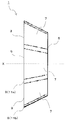
- FIG. 1 It is a perspective view which shows the cutting tool of the 1st Embodiment of this invention. It is a perspective view which shows the cutting insert of the 1st Embodiment of this invention. It is a top view of the cutting insert shown in FIG. It is a side view from the A1 direction in the cutting insert shown in FIG. It is a side view from the A2 direction in the cutting insert shown in FIG. It is the enlarged view to which area
- (A) is a conceptual diagram at the time of cutting using the cutting insert shown in FIG.
- (B) is a conceptual diagram at the time of cutting using the conventional cutting insert. It is the top view which expanded a part of modification 1 of the cutting insert shown in FIG.
- the cutting insert of one embodiment is explained in detail using a drawing.
- the drawings referred to below for convenience of explanation, among the constituent members of the embodiment, only the main members necessary for explaining the present invention are shown in a simplified manner. Therefore, the cutting insert of the present invention may include any component not shown in the drawings to which the present specification refers.
- the dimension of the member in each figure does not represent the dimension of an actual structural member, the dimension ratio of each member, etc. faithfully.
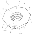
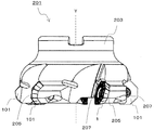
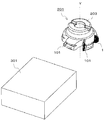
- a cutting insert 1 with a wiper blade of the present embodiment (hereinafter also referred to as a first insert 1 for convenience), as illustrated in FIG. 1, is an insert pocket 205 positioned on the distal end side of a tool body 203 described later. It is a cutting insert which is detachably attached to.
- a cutting tool 201 used for milling illustrated in FIG. 1 includes a tool main body 203, a first insert 1 having a wiper blade attached to the tool main body 203, and a cutting insert 101 having no wiper blade (hereinafter referred to as a “cutting tool”). For convenience, it is also referred to as a second insert 101).
- the first insert 1 of the present embodiment includes a substantially polygonal upper surface 3, a lower surface 5, side surfaces 7 connected to the upper surface 3 and the lower surface 5, respectively, A cutting edge 9 is provided at the intersection with the side surface 7.
- the upper surface 3 functions as a rake face through which chips flow during cutting.
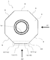
- the upper surface 3 has a substantially polygonal shape, and has a substantially octagonal shape in the present embodiment.
- the substantially polygonal shape does not mean strictly a polygonal shape.
- the corner portions on the upper surface 3 in the present embodiment are not strict corners, but are rounded.
- the side portions on the upper surface 3 are not strictly linear, but are slightly curved as will be described later.
- the lower surface 5 is a surface located on the side opposite to the upper surface 3 and functions as a seating surface for the insert pocket when the first insert 1 is attached to the tool body.
- the lower surface 5 in the present embodiment has a substantially polygonal shape, specifically a substantially octagonal shape, like the upper surface 3. At this time, the lower surface 5 is configured to be slightly smaller than the upper surface 3. Therefore, the lower surface 5 is configured to be similar to the upper surface 3.
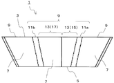
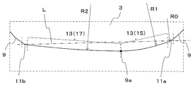
- the cutting blade 9 in the present embodiment has a first corner blade 11a and a second corner blade 11b, and at least one wiper blade 13.
- the first corner blade 11 a and the second corner blade 11 b are respectively located at corners adjacent to each other on the upper surface 3. Since the corner portion of the upper surface 3 has a rounded shape as described above, the first corner blade 11a and the second corner blade 11b each have an arc shape when viewed from above.
- the first corner blade 11a is located on the outer peripheral side of the tool body with respect to the second corner blade 11b when the first insert 1 is attached to the tool body.
- the second corner blade 11b is positioned closer to the inner peripheral side of the tool body than the first corner blade 11a when the first insert 1 is attached to the tool body.
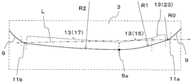
- FIG. 6 the right side corresponds to the outer peripheral side of the tool body, and the left side corresponds to the inner peripheral side of the tool body. Further, the lower side of FIG. 6 corresponds to the tip direction from the tool body, in other words, the direction protruding toward the work material.
- the wiper blade 13 is located between the first corner blade 11a and the second corner blade 11b adjacent to each other, that is, on the side of the upper surface 3.
- the wiper blade 13 functions as a cutting blade that finishes the processed surface of the work material smoothly. Therefore, when the first insert 1 is attached to the tool body, the wiper blade 13 includes the tip portion 9a that protrudes most from the tool body in the tip direction, in other words, toward the work material. Is provided.
- the tip end portion 9a is located at a portion farthest from the virtual straight line L connecting the center of the first corner blade 11a and the center of the second corner blade 11b when the wiper blade 13 is viewed from above. ing.
- the wiper blade 13 in the present embodiment has a first wiper blade 15 and a second wiper blade 17.
- the first wiper blade 15 is located closer to the first corner blade 11 a than the second wiper blade 17. Therefore, the first wiper blade 15 is located on the outer peripheral side of the tool body with respect to the second wiper blade 17 when the first insert 1 is attached to the tool body.
- at least a part of the first wiper blade 15 is provided so as to be positioned on the outer peripheral side of the tool main body with respect to the tip portion 9a.
- the second wiper blade 17 is located closer to the second corner blade 11b than the first wiper blade 15. Therefore, the second wiper blade 17 is provided so as to be positioned closer to the inner peripheral side of the tool body than the first wiper blade 15. In other words, the second wiper blade 17 is provided so as to be positioned closer to the rotation center axis side of the tool body than the first wiper blade 15. In the present embodiment, the second wiper blade is provided so that at least a part of the second wiper blade is located on the inner peripheral side of the tool body with respect to the tip end portion 9a when the first insert 1 is attached to the tool body. Yes.
- the first wiper blade 15 and the second wiper blade 17 are continuous.
- the first wiper blade 15 and the second wiper blade 15 are located at the furthest part from the virtual straight line L connecting the center of the first corner blade 11a and the center of the second corner blade 11b.
- the boundary with the wiper blade 17 is located.
- the tip end portion 9 a is located at the boundary between the first wiper blade 15 and the second wiper blade 17. Therefore, the entire first wiper blade 15 is provided so as to be positioned on the outer peripheral side of the tool body with respect to the tip end portion 9a. Further, the entire second wiper blade 17 is provided so as to be located on the inner peripheral side of the tool body with respect to the tip end portion 9a.
- the tip end portion 9 a of the cutting edge 9 is located at the lowest position among the cutting edges 9.
- the first wiper blade 15 is provided so as to be positioned on the outer peripheral side of the tool body, that is, on the right side in FIG. 6 among the wiper blades 13 sandwiched between the first corner blade 11a and the second corner blade 11b. And is continuous with the first corner blade 11a.
- the second wiper blade 17 is positioned on the inner peripheral side of the tool body, that is, on the left side in FIG. 6, of the wiper blade 13 sandwiched between the first corner blade 11a and the second corner blade 11b. It is provided and continues to the second corner blade 11b.
- the first wiper blade 15 and the second wiper blade 17 are each formed to have an arc shape when viewed from above.
- the radius of curvature of the first corner blade 11a and the second corner blade 11b is R0
- the radius of curvature of the first wiper blade 15 is R1
- the radius of curvature of the second wiper blade 17 is R2.
- the wiper blade 13 having a large curvature radius is positioned between the first corner blade 11a and the second corner blade 11b having a small curvature radius.
- the wiper blade 13 has a curved shape instead of a linear shape.
- the wiper blade 13 is not a simple circular arc shape consisting of a single arc, but is positioned on the outer peripheral side during cutting, the first wiper blade 15 having a relatively small radius of curvature, and the inner peripheral side during cutting And a second wiper blade 17 having a relatively large radius of curvature.
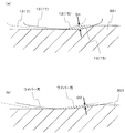
- the chip thickness D2 is very small, as shown in FIG. 7B.
- the locus of the wiper blade that cuts the workpiece 301 first is indicated by a one-dot chain line.
- the radius of curvature of the first wiper blade 15 is relatively small. Therefore, the cutting angle of the entire first wiper blade 15 is increased, and excessive cutting of the work material 301 by the wiper blade 13 that previously cuts the work material 301, which is indicated by a dashed line, is suppressed. The Thereby, when cutting with the cutting insert 1 with a wiper blade shown with a continuous line next, the thickness D1 of the chip cut with the 2nd wiper blade 17 is securable.
- the overall cutting angle of the first wiper blade 15 is defined by an imaginary straight line connecting one end and the other end of the first wiper blade 15 to the work surface of the work material. Means an angle.
- the curvature radius R0 of the first corner blade 11a and the second corner blade 11b in the above embodiment is set to about 0.4 to 2 mm.
- the radius of curvature R1 of the first wiper blade 15 is set to about 50 to 200 mm.
- the radius of curvature R2 of the second wiper blade 17 is set to about 200 to 800 mm.
- the wiper blade 13 located on the side of the upper surface 3 is constituted by an arc-shaped first wiper blade 15 and an arc-shaped second wiper blade 17. Therefore, the side portion on the upper surface 3 has a slightly curved shape.
- the second wiper blade 17 is longer than the first wiper blade 15. As a result, the length of the second wiper blade 17 can be ensured while ensuring a large cutting angle of the first wiper blade 15. Therefore, since the length of the second wiper blade 17 having a relatively small cutting angle can be ensured, the flatness of the processed surface can be improved.
- the intersecting line portion between the upper surface 3 and the side surface 7 may not be a strict line shape due to the intersection of the two surfaces.
- the intersection line between the upper surface 3 and the side surface 7 is sharp, the durability of the cutting blade 9 is lowered.
- a portion where the upper surface 3 and the side surface 7 intersect with each other may be slightly curved so-called honing.
- Examples of the material of the first insert 1 include cemented carbide or cermet.
- the composition of the cemented carbide is, for example, WC—Co produced by adding cobalt (Co) powder to tungsten carbide (WC) and sintering, and WC—coating WC—Co with titanium carbide (TiC).
- WC—TiC—TaC—Co in which tantalum carbide (TaC) is added to TiC—Co or WC—TiC—Co.
- the cermet is a sintered composite material in which a metal is combined with a ceramic component, and specifically includes a titanium compound mainly composed of titanium carbide (TiC) or titanium nitride (TiN).
- the surface of the first insert 1 may be coated with a film using a chemical vapor deposition (CVD) method or a physical vapor deposition (PVD) method.
- CVD chemical vapor deposition
- PVD physical vapor deposition
- the composition of the coating include titanium carbide (TiC), titanium nitride (TiN), titanium carbonitride (TiCN), and alumina (Al 2 O 3 ).
- the shapes of the upper surface 3 and the lower surface 5 are not limited to the above forms.
- the shape of the upper surface 3 when viewed from above is substantially octagonal.
- the shape of the upper surface 3 when viewed from above is triangular, quadrangular, pentagonal or hexagonal. Such a polygonal shape may be used.
- a through hole 19 is formed from the center of the upper surface 3 to the center of the lower surface 5.
- the through hole 19 is provided for inserting a screw when the first insert 1 is screwed and fixed to the tool body of the cutting tool.
- the direction of the central axis X of the through hole 19, in other words, the through direction is orthogonal to the upper surface 3 and the lower surface 5.
- the maximum width when the top surface 3 of the first insert 1 of the present embodiment is viewed from above is 20 to 30 mm.
- the height from the lower surface 5 to the upper surface 3 is 3 to 7 mm.
- the height from the lower surface 5 to the upper surface 3 means a width in a direction parallel to the through hole 19 between the upper end of the upper surface 3 and the lower end of the lower surface 5.
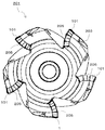
- the cutting tool 201 of the present embodiment has a rotation center axis Y and a tool body 203 (hereinafter also referred to as a holder 203) having a plurality of insert pockets 205 on the outer peripheral surface on the distal end side.
- the first insert 1 mounted in at least one of the insert pockets 205, and the second insert 101 mounted in the insert pocket 205 in which the first insert 1 is not mounted. Yes.
- the second insert 101 has a configuration similar to that of the first insert 1 and does not have the wiper blade 13 in the first insert 1. Specifically, like the first insert 1, the second insert 101 has a substantially polygonal upper and lower surfaces and side surfaces between the upper and lower surfaces. Further, a cutting edge is formed at the intersection of the upper surface and the side surface of the second insert 101. However, the cutting blade in the second insert 101 does not have a wiper blade.
- the portion of the second insert 101 corresponding to the wiper blade 13 connecting the first corner blade 11a and the second corner blade 11b of the first insert 1 has a linear shape. Therefore, when the first insert 1 and the second insert 101 are mounted on the holder 203, the above-mentioned cutting blade portion of the second insert 101 is located behind the holder 203 rather than the wiper blade 13 of the first insert 1. Located on the end side. As described above, the wiper blade 13 in the first insert 1 protrudes in the distal direction from the cutting blade in the second insert 101, so that the processed surface of the work material can be satisfactorily finished with the wiper blade 13. it can.
- the first insert 1 provided with the wiper blade 13 is subjected to a larger load than the second insert 101 not provided with the wiper blade. Therefore, only the plurality of first inserts 1 may be attached to the holder 203, but in general, the second insert 101 is also attached to the holder 203 in addition to the first insert 1.
- the number of the second insert 101 is usually larger than that of the first insert 1. Mounted on the holder 203.
- the holder 203 has a substantially rotating body shape around the rotation center axis Y.
- a plurality of insert pockets 205 are provided at equal intervals on the outer peripheral surface on the tip side of the holder 203.
- the insert pocket 205 is a part to which the first insert 1 or the second insert 101 is attached, and is open to the outer peripheral surface and the front end surface of the holder 203.
- the insert pocket 205 has a seating surface that opposes the rotation direction and two restraint side surfaces that are positioned in a direction in which the seating surface intersects.
- the first insert 1 or the second insert 101 is mounted in a plurality of insert pockets 205 provided in the holder 203.
- the first insert 1 is attached to the holder 203 so that at least the wiper blade 13 of the cutting edge 9 protrudes from the holder 203 in the distal direction.
- the tip 9 a of the wiper blade 13 is positioned so as to protrude most from the holder 203 in the tip direction.
- the first insert 1 is mounted in the insert pocket 205 so that the wiper blade 13 of the cutting blade 9 protrudes most from the holder 203 in the distal direction.
- the second insert 101 is mounted on the holder 203 so that a cutting blade formed on the outer periphery of the upper surface protrudes from the holder 203 in the distal direction. At this time, as described above, the wiper blade 13 in the first insert 1 protrudes in the distal direction from the cutting blade in the second insert 101.
- the wiper blade 13 has a first wiper blade 15 and a second wiper blade 17 instead of a straight arc shape or a simple arc shape consisting of one arc. ing.
- a first wiper blade 15 and a second wiper blade 17 instead of a straight arc shape or a simple arc shape consisting of one arc.
- the first insert 1 and the second insert 101 are mounted in the insert pocket 205 by screws 207, respectively. That is, screws 207 are inserted into the through holes 19 of the first insert 1 and the second insert 101, respectively, and the tips of these screws 207 are inserted into screw holes (not shown) formed in the insert pocket 205.
- the first insert 1 and the second insert 101 are fixed to the holder 203 by screwing the parts together.
- steel, cast iron or the like can be used as the holder 203.
- steel with high toughness is used among these members.
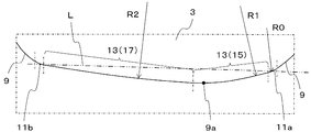
- FIG. 8 is an enlarged top view of a part of the first modification and corresponding to the region shown in FIG. 6 in the first insert 1 shown in FIG.
- the tip end portion 9a is located at the boundary between the first wiper blade 15 and the second wiper blade 17, but the first wiper blade 15 and the second wiper blade 15
- the position of the wiper blade 17 is not limited to such a form.
- the first wiper blade 15 may be at least partially positioned on the outer peripheral side of the tool main body with respect to the tip end portion 9a. Therefore, as shown in FIG. 8, a configuration in which the tip end portion 9 a is included in the first wiper blade 15 may be employed.
- the 2nd wiper blade 17 whole is provided so that it may be located in the inner peripheral side of a tool main body rather than the front-end
- transformation is carried out.
- a configuration in which the distal end portion 9a is included in the second wiper blade 17 may be employed.
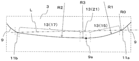
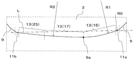
- Modification 2 of the first insert 1 of the above embodiment will be described with reference to FIG. 9 is an enlarged top view of a part of the second modification and corresponding to the region shown in FIG. 6 in the first insert 1 shown in FIG.
- the wiper blade 13 is constituted by the first wiper blade 15 and the second wiper blade 17, but the configuration of the wiper blade 13 is such a form. It is not limited.
- the wiper blade 13 further includes an arc-shaped third wiper blade 21 located between the first wiper blade 15 and the second wiper blade 17. Yes.
- the curvature radius R3 of the third wiper blade 21 is set to about 200 to 800 mm.
- R1 ⁇ R3 ⁇ R2 is satisfied.
- the present invention is not particularly limited to this, and may be R1 ⁇ R2 ⁇ R3, for example.
- the wiper blade 13 has such a third wiper blade 21, it is easy to increase the cutting angle of the first wiper blade 15. Therefore, it becomes easier to ensure a larger thickness of chips cut by the second wiper blade 17. As a result, when the third wiper blade 21 is provided, the finished surface can be further improved.
- the third wiper blade 21 is positioned so as to include the tip portion 9a. ing.
- the third wiper blade 21 moves the wiper blade 13 to the upper surface. When viewed, it is positioned so as to include a portion farthest from the virtual straight line L connecting the center of the first corner blade 11a and the center of the second corner blade 11b.
- the length of the third wiper blade 21 is shorter than the lengths of the first wiper blade 15 and the second wiper blade 17. Thereby, the length of the 1st wiper blade 15 and the 2nd wiper blade 17 is securable, without making the length of the wiper blade 13 whole too large.
- FIG. 10 is an enlarged top view of a part of the third modification and corresponding to the region shown in FIG. 6 in the first insert 1 shown in FIG.
- the wiper blade 13 is configured by the arc-shaped first wiper blade 15 and the arc-shaped second wiper blade 17.
- the present invention is not limited to such a form.
- the wiper blade 13 further includes a linear first straight blade 23 that connects the first corner blade 11a and the first wiper blade 15.
- the tool body is located on the outer peripheral side of the tip portion 9a of the wiper blade 13 which is configured by the first wiper blade 15 and the first linear blade 23. The length of the located part can be shortened.
- FIG. 11 is an enlarged top view of a part of the modification 4 and corresponding to the region shown in FIG. 6 in the first insert 1 shown in FIG.
- the wiper blade 13 further includes the linear first straight blade 23 that connects the first corner blade 11 a and the first wiper blade 15.
- the wiper blade 13 has a linear second straight blade 25 that connects the second corner blade 11 b and the second wiper blade 17.
- the wiper blade 13 has such a configuration, the inner peripheral side of the tool body with respect to the tip end portion 9a of the wiper blade 13 constituted by the second wiper blade 17 and the second linear blade 25.
- the cut angle of the entire portion located at can be reduced. Therefore, the surface roughness of the finished surface of the work material can be reduced.
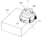
- the cut workpiece is produced by cutting the work material 301.
- the manufacturing method in the present embodiment includes the following steps. That is, (1) a step of rotating a cutting tool 201 typified by the above embodiment; (2) a step of bringing the cutting edge 9 in the rotating cutting tool 201 into contact with the work material 301; (3) a step of separating the cutting tool 201 from the work material 301; It has.
- the cutting tool 201 is relatively moved closer to the work material 301 while being rotated.
- the cutting blade 9 in the first insert 1 and the cutting blade in the second insert 101 are brought into contact with the workpiece 301 to cut the workpiece 301.
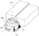
- the cutting tool 201 is relatively moved away from the work material 301.
- the work material 301 is fixed and the cutting tool 201 is brought closer. 14 and 15, the work material 301 is fixed and the cutting tool 201 is rotated. In FIG. 16, the work material 301 is fixed and the cutting tool 201 is moved away. In the cutting in the manufacturing method of the present embodiment, the work material 301 is fixed and the cutting tool 201 is moved in each step, but it is naturally not limited to such a form.
- the work material 301 may be brought close to the cutting tool 201 in the step (1). Similarly, the work material 301 may be moved away from the cutting tool 201 in the step (3).
- the state where the cutting tool 201 is rotated is maintained, and the cutting blade 9 of the first insert 1 and the cutting blade of the second insert 101 are brought into contact with different portions of the work material 301. What is necessary is just to repeat the process to make.
- representative examples of the material of the work material 301 include carbon steel, alloy steel, stainless steel, cast iron, and non-ferrous metal.
- Cutting insert (first insert) DESCRIPTION OF SYMBOLS 3 ... Upper surface 5 ... Lower surface 7 ... Side surface 9 ... Cutting edge 9a ... Tip part 11a ... 1st corner blade 11b ... 2nd corner blade 13 ... Wiper Blade 15 ... first wiper blade 17 ... second wiper blade 19 ... through hole 21 ... third wiper blade 23 ... first linear blade 25 ... second Straight blade 101 ... cutting insert (second insert) 201: Cutting tool 203 ... Tool body (holder) 205 ... Insert pocket 207 ... Screw 301 ... Work material
Landscapes
- Engineering & Computer Science (AREA)
- Mechanical Engineering (AREA)
- Milling Processes (AREA)
Abstract
Description
以下、一実施形態の切削インサートについて、図面を用いて詳細に説明する。但し、以下で参照する各図は、説明の便宜上、実施形態の構成部材のうち、本発明を説明するために必要な主要部材のみを簡略化して示したものである。したがって、本発明の切削インサートは、本明細書が参照する各図に示されていない任意の構成部材を備え得る。また、各図中の部材の寸法は、実際の構成部材の寸法及び各部材の寸法比率等を忠実に表したものではない。
次に、本発明の一実施形態の切削工具201について図面を用いて説明する。
次に、上記の実施形態の第1のインサート1の変形例1について図8を用いて説明する。なお、図8は、変形例1の一部であって、図3に示す第1のインサート1における図6に示す領域に対応する部分を拡大した上面図である。
次に、上記の実施形態の第1のインサート1の変形例2について図9を用いて説明する。なお、図9は、変形例2の一部であって、図3に示す第1のインサート1における図6に示す領域に対応する部分を拡大した上面図である。
次に、上記の実施形態の第1のインサート1の変形例3について図10を用いて説明する。なお、図10は、変形例3の一部であって、図3に示す第1のインサート1における図6に示す領域に対応する部分を拡大した上面図である。
次に、上記の実施形態の第1のインサート1の変形例4について図11を用いて説明する。なお、図11は、変形例4の一部であって、図3に示す第1のインサート1における図6に示す領域に対応する部分を拡大した上面図である。
次に、本発明の一実施形態の切削加工物の製造方法について図面を用いて説明する。
(1)上記実施形態に代表される切削工具201を回転させる工程と、
(2)回転している切削工具201における切刃9を被削材301に接触させる工程と、
(3)切削工具201を被削材301から離す工程と、
を備えている。
3・・・上面
5・・・下面
7・・・側面
9・・・切刃
9a・・・先端部
11a・・・第1のコーナ刃
11b・・・第2のコーナ刃
13・・・ワイパー刃
15・・・第1のワイパー刃
17・・・第2のワイパー刃
19・・・貫通孔
21・・・第3のワイパー刃
23・・・第1の直線刃
25・・・第2の直線刃
101・・・切削インサート(第2のインサート)
201・・・切削工具
203・・・工具本体(ホルダ)
205・・・インサートポケット
207・・・ネジ
301・・・被削材
Claims (12)
- 多角形状の上面と、下面と、前記上面及び前記下面のそれぞれに接続された側面と、前記上面と前記側面との交線部に位置する切刃とを備え、
前記切刃は、前記上面における互いに隣り合う角部に位置する円弧形状の第1のコーナ刃及び第2のコーナ刃と、前記第1のコーナ刃及び前記第2のコーナ刃の間に位置するワイパー刃とを有し、
前記ワイパー刃は、円弧形状の第1のワイパー刃と、前記第1のワイパー刃よりも前記第2のコーナ刃の側に位置する円弧形状の第2のワイパー刃とを有し、
上面視において、前記第1のワイパー刃の曲率半径をR1、前記第2のワイパー刃の曲率半径をR2、前記第1のコーナ刃及び前記第2のコーナ刃の曲率半径をR0とした場合に、R0<R1<R2となることを特徴とする切削インサート。 - 前記ワイパー刃は、前記第1のワイパー刃と前記第2のワイパー刃との間に位置する円弧形状の第3のワイパー刃をさらに有しており、
上面視において、前記第3のワイパー刃の曲率半径をR3とした場合に、R1<R3となることを特徴とする請求項1に記載の切削インサート。 - 前記第3のワイパー刃は、前記ワイパー刃を上面視した場合において、前記第1のコーナ刃の中心と前記第2のコーナ刃の中心とを結ぶ仮想直線から最も離れた部位を含むように位置していることを特徴とする請求項2に記載の切削インサート。
- 前記第3のワイパー刃は、前記第1のワイパー刃及び前記第2のワイパー刃よりも短いことを特徴とする請求項2又は3に記載の切削インサート。
- 前記第2のワイパー刃は、前記第1のワイパー刃よりも長いことを特徴とする請求項1~4のいずれか1つに記載の切削インサート。
- 前記切刃は、前記第1のコーナ刃と前記第1のワイパー刃とを接続する直線形状の第1の直線刃をさらに有していることを特徴とする請求項1~5のいずれか1つに記載の切削インサート。
- 前記切刃は、前記第2のコーナ刃と前記第2のワイパー刃とを接続する直線形状の第2の直線刃をさらに有していることを特徴とする請求項1~6のいずれか1つに記載の切削インサート。
- 前記第1のワイパー刃と前記第2のワイパー刃とが連続しており、
前記ワイパー刃を上面視した場合において、前記第1のコーナ刃の中心と前記第2のコーナ刃の中心とを結ぶ仮想直線から最も離れた部分に前記第1のワイパー刃と前記第2のワイパー刃との境界が位置していることを特徴とする請求項1に記載の切削インサート。 - 先端側にインサートポケットを有する工具本体と、
前記切刃が前記工具本体から突出するように前記インサートポケットに装着された、請求項1~8のいずれか1つに記載の切削インサートとを具備している切削工具。 - 前記切刃のうち前記ワイパー刃が前記工具本体から先端方向に最も突出するように前記切削インサートが前記インサートポケットに装着されていることを特徴とする請求項9に記載の切削工具。
- 前記第1のワイパー刃は、少なくとも一部が前記切刃のうち前記工具本体から先端方向に最も突出する部分よりも前記工具本体の外周側に位置していることを特徴とする請求項9又は10に記載の切削工具。
- 請求項9~11のいずれか1つに記載の切削工具を回転させる工程と、
回転している前記切削工具における前記切刃を被削材に接触させる工程と、
前記切削工具を前記被削材から離す工程とを備えた切削加工物の製造方法。
Priority Applications (5)
| Application Number | Priority Date | Filing Date | Title |
|---|---|---|---|
| JP2015549135A JP6194013B2 (ja) | 2013-11-19 | 2014-11-17 | 切削インサート、切削工具及び被削加工物の製造方法 |
| US15/037,197 US9884378B2 (en) | 2013-11-19 | 2014-11-17 | Cutting insert, cutting tool, and method of manufacturing machined product |
| CN201480063029.2A CN105745046B (zh) | 2013-11-19 | 2014-11-17 | 切削镶刀、切削工具以及被切削加工物的制造方法 |
| EP14863741.6A EP3072617B1 (en) | 2013-11-19 | 2014-11-17 | Cutting insert, cutting tool, and method for producing cut article |
| US15/858,213 US10124426B2 (en) | 2013-11-19 | 2017-12-29 | Cutting insert, cutting tool, and method of manufacturing machined product |
Applications Claiming Priority (2)
| Application Number | Priority Date | Filing Date | Title |
|---|---|---|---|
| JP2013-239128 | 2013-11-19 | ||
| JP2013239128 | 2013-11-19 |
Related Child Applications (2)
| Application Number | Title | Priority Date | Filing Date |
|---|---|---|---|
| US15/037,197 A-371-Of-International US9884378B2 (en) | 2013-11-19 | 2014-11-17 | Cutting insert, cutting tool, and method of manufacturing machined product |
| US15/858,213 Continuation US10124426B2 (en) | 2013-11-19 | 2017-12-29 | Cutting insert, cutting tool, and method of manufacturing machined product |
Publications (1)
| Publication Number | Publication Date |
|---|---|
| WO2015076216A1 true WO2015076216A1 (ja) | 2015-05-28 |
Family
ID=53179479
Family Applications (1)
| Application Number | Title | Priority Date | Filing Date |
|---|---|---|---|
| PCT/JP2014/080315 Ceased WO2015076216A1 (ja) | 2013-11-19 | 2014-11-17 | 切削インサート、切削工具及び被削加工物の製造方法 |
Country Status (5)
| Country | Link |
|---|---|
| US (2) | US9884378B2 (ja) |
| EP (1) | EP3072617B1 (ja) |
| JP (1) | JP6194013B2 (ja) |
| CN (1) | CN105745046B (ja) |
| WO (1) | WO2015076216A1 (ja) |
Cited By (2)
| Publication number | Priority date | Publication date | Assignee | Title |
|---|---|---|---|---|
| US11407043B2 (en) | 2019-12-13 | 2022-08-09 | Tungaloy Corporation | Cutting insert |
| WO2023281889A1 (ja) * | 2021-07-08 | 2023-01-12 | 兼房株式会社 | 回転切削工具 |
Families Citing this family (7)
| Publication number | Priority date | Publication date | Assignee | Title |
|---|---|---|---|---|
| WO2017090770A1 (ja) * | 2015-11-28 | 2017-06-01 | 京セラ株式会社 | 切削インサート、切削工具及び切削加工物の製造方法 |
| AT15155U1 (de) * | 2016-02-26 | 2017-01-15 | Ceratizit Austria Gmbh | Schälplatte |
| CN106113171A (zh) * | 2016-08-17 | 2016-11-16 | 江苏飞达钻头股份有限公司 | 木工修光、扩孔钻 |
| JP7093784B2 (ja) * | 2017-09-27 | 2022-06-30 | 京セラ株式会社 | 切削インサート、切削工具及び切削加工物の製造方法 |
| DE102019123912A1 (de) | 2019-09-05 | 2021-03-11 | Kennametal Inc. | Schneideinsatz sowie Schneidwerkzeug |
| JP6858354B1 (ja) * | 2019-12-13 | 2021-04-14 | 株式会社タンガロイ | 切削インサート |
| CN114799299A (zh) * | 2022-05-31 | 2022-07-29 | 厦门金鹭特种合金有限公司 | 精加工修光刀具 |
Citations (7)
| Publication number | Priority date | Publication date | Assignee | Title |
|---|---|---|---|---|
| JP2000005903A (ja) * | 1998-06-05 | 2000-01-11 | Sandvik Ab | 切削チップ |
| JP2001138122A (ja) | 1999-11-17 | 2001-05-22 | Mitsubishi Materials Corp | ワイパー刃付きスローアウェイチップ及び転削工具 |
| JP2001198724A (ja) * | 2000-01-21 | 2001-07-24 | Mitsubishi Materials Corp | スローアウェイチップ及びスローアウェイ式転削工具 |
| JP2007044782A (ja) * | 2005-08-08 | 2007-02-22 | Sumitomo Electric Hardmetal Corp | スローアウェイチップ及びそれを用いたミーリングカッタ |
| JP2008006579A (ja) * | 2006-06-27 | 2008-01-17 | Sandvik Intellectual Property Ab | 正面フライスインサート |
| WO2013002341A1 (ja) * | 2011-06-30 | 2013-01-03 | 京セラ株式会社 | 切削インサートおよび切削工具ならびにそれを用いた切削加工物の製造方法 |
| JP2013176834A (ja) * | 2011-12-12 | 2013-09-09 | Mitsubishi Materials Corp | 切削インサートおよび刃先交換式切削工具 |
Family Cites Families (13)
| Publication number | Priority date | Publication date | Assignee | Title |
|---|---|---|---|---|
| JP3317490B2 (ja) * | 1998-06-18 | 2002-08-26 | 日立ツール株式会社 | 高送りスローアウェイ式回転工具 |
| KR100916280B1 (ko) * | 2001-05-25 | 2009-09-10 | 히타치 쓰루 가부시키가이샤 | 날끝 교환식 회전 공구 |
| IL150783A0 (en) * | 2001-10-16 | 2003-02-12 | Iscar Ltd | Cutting tool and cutting insert therefor |
| JP2004255521A (ja) | 2003-02-26 | 2004-09-16 | Tungaloy Corp | 転削工具 |
| US20040232535A1 (en) | 2003-05-22 | 2004-11-25 | Terry Tarn | Microelectromechanical device packages with integral heaters |
| US7220083B2 (en) * | 2003-10-15 | 2007-05-22 | Tdy Industries, Inc. | Cutting insert for high feed face milling |
| JP4779864B2 (ja) | 2006-08-09 | 2011-09-28 | 株式会社タンガロイ | スローアウェイチップおよびスローアウェイ式切削工具 |
| KR20120024666A (ko) * | 2009-06-16 | 2012-03-14 | 가부시키가이샤 탕가로이 | 절삭용 인서트 및 정면 밀링 커터 |
| EP2450139B1 (en) * | 2009-06-29 | 2019-03-27 | Kyocera Corporation | Cutting insert, cutting tool, and manufacturing method for cut product using the same |
| DE102009035754A1 (de) * | 2009-07-24 | 2011-01-27 | Hartmetall-Werkzeugfabrik Paul Horn Gmbh | Schneideinsatz für ein Schneidwerkzeug zur spanenden Bearbeitung, insbesondere zum Hochvorschubfräsen |
| JP5620929B2 (ja) * | 2010-01-29 | 2014-11-05 | 京セラ株式会社 | 切削インサートおよび切削工具、並びにそれを用いた切削加工物の製造方法 |
| AT12004U1 (de) * | 2010-02-25 | 2011-09-15 | Ceratizit Austria Gmbh | Schneideinsatz |
| JP5401732B1 (ja) | 2012-10-23 | 2014-01-29 | 住友電工ハードメタル株式会社 | フライス加工用刃先交換式切削インサート |
-
2014
- 2014-11-17 US US15/037,197 patent/US9884378B2/en active Active
- 2014-11-17 CN CN201480063029.2A patent/CN105745046B/zh active Active
- 2014-11-17 WO PCT/JP2014/080315 patent/WO2015076216A1/ja not_active Ceased
- 2014-11-17 JP JP2015549135A patent/JP6194013B2/ja active Active
- 2014-11-17 EP EP14863741.6A patent/EP3072617B1/en active Active
-
2017
- 2017-12-29 US US15/858,213 patent/US10124426B2/en active Active
Patent Citations (7)
| Publication number | Priority date | Publication date | Assignee | Title |
|---|---|---|---|---|
| JP2000005903A (ja) * | 1998-06-05 | 2000-01-11 | Sandvik Ab | 切削チップ |
| JP2001138122A (ja) | 1999-11-17 | 2001-05-22 | Mitsubishi Materials Corp | ワイパー刃付きスローアウェイチップ及び転削工具 |
| JP2001198724A (ja) * | 2000-01-21 | 2001-07-24 | Mitsubishi Materials Corp | スローアウェイチップ及びスローアウェイ式転削工具 |
| JP2007044782A (ja) * | 2005-08-08 | 2007-02-22 | Sumitomo Electric Hardmetal Corp | スローアウェイチップ及びそれを用いたミーリングカッタ |
| JP2008006579A (ja) * | 2006-06-27 | 2008-01-17 | Sandvik Intellectual Property Ab | 正面フライスインサート |
| WO2013002341A1 (ja) * | 2011-06-30 | 2013-01-03 | 京セラ株式会社 | 切削インサートおよび切削工具ならびにそれを用いた切削加工物の製造方法 |
| JP2013176834A (ja) * | 2011-12-12 | 2013-09-09 | Mitsubishi Materials Corp | 切削インサートおよび刃先交換式切削工具 |
Cited By (6)
| Publication number | Priority date | Publication date | Assignee | Title |
|---|---|---|---|---|
| US11407043B2 (en) | 2019-12-13 | 2022-08-09 | Tungaloy Corporation | Cutting insert |
| WO2023281889A1 (ja) * | 2021-07-08 | 2023-01-12 | 兼房株式会社 | 回転切削工具 |
| JPWO2023281889A1 (ja) * | 2021-07-08 | 2023-01-12 | ||
| JP7403033B2 (ja) | 2021-07-08 | 2023-12-21 | 兼房株式会社 | 回転切削工具 |
| CN117425537A (zh) * | 2021-07-08 | 2024-01-19 | 兼房株式会社 | 旋转切削工具 |
| CN117425537B (zh) * | 2021-07-08 | 2024-06-04 | 兼房株式会社 | 旋转切削工具 |
Also Published As
| Publication number | Publication date |
|---|---|
| JPWO2015076216A1 (ja) | 2017-03-16 |
| JP6194013B2 (ja) | 2017-09-06 |
| US10124426B2 (en) | 2018-11-13 |
| US20180117686A1 (en) | 2018-05-03 |
| CN105745046A (zh) | 2016-07-06 |
| US20160288224A1 (en) | 2016-10-06 |
| US9884378B2 (en) | 2018-02-06 |
| CN105745046B (zh) | 2018-08-24 |
| EP3072617B1 (en) | 2019-06-26 |
| EP3072617A4 (en) | 2017-07-19 |
| EP3072617A1 (en) | 2016-09-28 |
Similar Documents
| Publication | Publication Date | Title |
|---|---|---|
| JP6194013B2 (ja) | 切削インサート、切削工具及び被削加工物の製造方法 | |
| JP6343016B2 (ja) | 切削インサート、切削工具及び切削加工物の製造方法 | |
| JP6356781B2 (ja) | 切削インサート、切削工具及び切削加工物の製造方法 | |
| JP5591409B2 (ja) | 切削インサート、切削工具および被削加工物の製造方法 | |
| JP6386524B2 (ja) | 転削工具用切削インサート、転削工具および切削加工物の製造方法 | |
| JP6462845B2 (ja) | インサート、ドリル及びそれを用いた切削加工物の製造方法 | |
| JP6609638B2 (ja) | 切削工具及び切削加工物の製造方法 | |
| US10239125B2 (en) | Cutting insert, cutting tool, and method for manufacturing machined product using same | |
| JP6272457B2 (ja) | 切削インサート、切削工具及び切削加工物の製造方法 | |
| JP6711842B2 (ja) | 切削インサート、切削工具及び切削加工物の製造方法 | |
| JP5905123B2 (ja) | 切削インサート、切削工具および切削加工物の製造方法 | |
| JP2014188606A (ja) | 切削インサート、切削工具および切削加工物の製造方法 | |
| JPWO2016186217A1 (ja) | ホルダ、切削工具及びこれを用いた切削加工物の製造方法 | |
| JP6352639B2 (ja) | 切削インサート、切削工具および切削加工物の製造方法 | |
| JP5952073B2 (ja) | 切削インサート、切削工具および被削加工物の製造方法 | |
| JP6430796B2 (ja) | 切削工具及び切削加工物の製造方法 | |
| JP2014124719A (ja) | 切削インサート、切削工具および切削加工物の製造方法 | |
| JP5762020B2 (ja) | 切削インサートおよび切削工具ならびにそれを用いた被削材の切削方法 | |
| JP2017064869A (ja) | 切削インサート、切削工具及びそれを用いた切削加工物の製造方法 |
Legal Events
| Date | Code | Title | Description |
|---|---|---|---|
| 121 | Ep: the epo has been informed by wipo that ep was designated in this application |
Ref document number: 14863741 Country of ref document: EP Kind code of ref document: A1 |
|
| ENP | Entry into the national phase |
Ref document number: 2015549135 Country of ref document: JP Kind code of ref document: A |
|
| WWE | Wipo information: entry into national phase |
Ref document number: 15037197 Country of ref document: US |
|
| REEP | Request for entry into the european phase |
Ref document number: 2014863741 Country of ref document: EP |
|
| WWE | Wipo information: entry into national phase |
Ref document number: 2014863741 Country of ref document: EP |
|
| NENP | Non-entry into the national phase |
Ref country code: DE |